EP4225645B1 - Aéronef comprenant un système d'entraînement et d'énergie pour un vol de croisière à faibles émissions - Google Patents
Aéronef comprenant un système d'entraînement et d'énergie pour un vol de croisière à faibles émissions Download PDFInfo
- Publication number
- EP4225645B1 EP4225645B1 EP21786762.1A EP21786762A EP4225645B1 EP 4225645 B1 EP4225645 B1 EP 4225645B1 EP 21786762 A EP21786762 A EP 21786762A EP 4225645 B1 EP4225645 B1 EP 4225645B1
- Authority
- EP
- European Patent Office
- Prior art keywords
- motor
- engine
- aircraft
- operating mode
- power
- Prior art date
- Legal status (The legal status is an assumption and is not a legal conclusion. Google has not performed a legal analysis and makes no representation as to the accuracy of the status listed.)
- Active
Links
Images




Classifications
-
- B—PERFORMING OPERATIONS; TRANSPORTING
- B64—AIRCRAFT; AVIATION; COSMONAUTICS
- B64D—EQUIPMENT FOR FITTING IN OR TO AIRCRAFT; FLIGHT SUITS; PARACHUTES; ARRANGEMENT OR MOUNTING OF POWER PLANTS OR PROPULSION TRANSMISSIONS IN AIRCRAFT
- B64D37/00—Arrangements in connection with fuel supply for power plant
- B64D37/30—Fuel systems for specific fuels
-
- B—PERFORMING OPERATIONS; TRANSPORTING
- B60—VEHICLES IN GENERAL
- B60L—PROPULSION OF ELECTRICALLY-PROPELLED VEHICLES; SUPPLYING ELECTRIC POWER FOR AUXILIARY EQUIPMENT OF ELECTRICALLY-PROPELLED VEHICLES; ELECTRODYNAMIC BRAKE SYSTEMS FOR VEHICLES IN GENERAL; MAGNETIC SUSPENSION OR LEVITATION FOR VEHICLES; MONITORING OPERATING VARIABLES OF ELECTRICALLY-PROPELLED VEHICLES; ELECTRIC SAFETY DEVICES FOR ELECTRICALLY-PROPELLED VEHICLES
- B60L50/00—Electric propulsion with power supplied within the vehicle
- B60L50/50—Electric propulsion with power supplied within the vehicle using propulsion power supplied by batteries or fuel cells
- B60L50/70—Electric propulsion with power supplied within the vehicle using propulsion power supplied by batteries or fuel cells using power supplied by fuel cells
- B60L50/71—Arrangement of fuel cells within vehicles specially adapted for electric vehicles
-
- B—PERFORMING OPERATIONS; TRANSPORTING
- B60—VEHICLES IN GENERAL
- B60L—PROPULSION OF ELECTRICALLY-PROPELLED VEHICLES; SUPPLYING ELECTRIC POWER FOR AUXILIARY EQUIPMENT OF ELECTRICALLY-PROPELLED VEHICLES; ELECTRODYNAMIC BRAKE SYSTEMS FOR VEHICLES IN GENERAL; MAGNETIC SUSPENSION OR LEVITATION FOR VEHICLES; MONITORING OPERATING VARIABLES OF ELECTRICALLY-PROPELLED VEHICLES; ELECTRIC SAFETY DEVICES FOR ELECTRICALLY-PROPELLED VEHICLES
- B60L58/00—Methods or circuit arrangements for monitoring or controlling batteries or fuel cells, specially adapted for electric vehicles
- B60L58/30—Methods or circuit arrangements for monitoring or controlling batteries or fuel cells, specially adapted for electric vehicles for monitoring or controlling fuel cells
- B60L58/32—Methods or circuit arrangements for monitoring or controlling batteries or fuel cells, specially adapted for electric vehicles for monitoring or controlling fuel cells for controlling the temperature of fuel cells, e.g. by controlling the electric load
- B60L58/33—Methods or circuit arrangements for monitoring or controlling batteries or fuel cells, specially adapted for electric vehicles for monitoring or controlling fuel cells for controlling the temperature of fuel cells, e.g. by controlling the electric load by cooling
-
- B—PERFORMING OPERATIONS; TRANSPORTING
- B64—AIRCRAFT; AVIATION; COSMONAUTICS
- B64D—EQUIPMENT FOR FITTING IN OR TO AIRCRAFT; FLIGHT SUITS; PARACHUTES; ARRANGEMENT OR MOUNTING OF POWER PLANTS OR PROPULSION TRANSMISSIONS IN AIRCRAFT
- B64D15/00—De-icing or preventing icing on exterior surfaces of aircraft
-
- B—PERFORMING OPERATIONS; TRANSPORTING
- B64—AIRCRAFT; AVIATION; COSMONAUTICS
- B64D—EQUIPMENT FOR FITTING IN OR TO AIRCRAFT; FLIGHT SUITS; PARACHUTES; ARRANGEMENT OR MOUNTING OF POWER PLANTS OR PROPULSION TRANSMISSIONS IN AIRCRAFT
- B64D27/00—Arrangement or mounting of power plants in aircraft; Aircraft characterised by the type or position of power plants
- B64D27/02—Aircraft characterised by the type or position of power plants
- B64D27/10—Aircraft characterised by the type or position of power plants of gas-turbine type
- B64D27/12—Aircraft characterised by the type or position of power plants of gas-turbine type within, or attached to, wings
-
- B—PERFORMING OPERATIONS; TRANSPORTING
- B64—AIRCRAFT; AVIATION; COSMONAUTICS
- B64D—EQUIPMENT FOR FITTING IN OR TO AIRCRAFT; FLIGHT SUITS; PARACHUTES; ARRANGEMENT OR MOUNTING OF POWER PLANTS OR PROPULSION TRANSMISSIONS IN AIRCRAFT
- B64D27/00—Arrangement or mounting of power plants in aircraft; Aircraft characterised by the type or position of power plants
- B64D27/02—Aircraft characterised by the type or position of power plants
- B64D27/30—Aircraft characterised by electric power plants
- B64D27/33—Hybrid electric aircraft
-
- B—PERFORMING OPERATIONS; TRANSPORTING
- B64—AIRCRAFT; AVIATION; COSMONAUTICS
- B64D—EQUIPMENT FOR FITTING IN OR TO AIRCRAFT; FLIGHT SUITS; PARACHUTES; ARRANGEMENT OR MOUNTING OF POWER PLANTS OR PROPULSION TRANSMISSIONS IN AIRCRAFT
- B64D27/00—Arrangement or mounting of power plants in aircraft; Aircraft characterised by the type or position of power plants
- B64D27/02—Aircraft characterised by the type or position of power plants
- B64D27/30—Aircraft characterised by electric power plants
- B64D27/35—Arrangements for on-board electric energy production, distribution, recovery or storage
- B64D27/355—Arrangements for on-board electric energy production, distribution, recovery or storage using fuel cells
-
- B—PERFORMING OPERATIONS; TRANSPORTING
- B64—AIRCRAFT; AVIATION; COSMONAUTICS
- B64D—EQUIPMENT FOR FITTING IN OR TO AIRCRAFT; FLIGHT SUITS; PARACHUTES; ARRANGEMENT OR MOUNTING OF POWER PLANTS OR PROPULSION TRANSMISSIONS IN AIRCRAFT
- B64D31/00—Power plant control systems; Arrangement of power plant control systems in aircraft
- B64D31/16—Power plant control systems; Arrangement of power plant control systems in aircraft for electric power plants
- B64D31/18—Power plant control systems; Arrangement of power plant control systems in aircraft for electric power plants for hybrid-electric power plants
-
- B—PERFORMING OPERATIONS; TRANSPORTING
- B64—AIRCRAFT; AVIATION; COSMONAUTICS
- B64D—EQUIPMENT FOR FITTING IN OR TO AIRCRAFT; FLIGHT SUITS; PARACHUTES; ARRANGEMENT OR MOUNTING OF POWER PLANTS OR PROPULSION TRANSMISSIONS IN AIRCRAFT
- B64D35/00—Transmitting power from power plants to propellers or rotors; Arrangements of transmissions
-
- B—PERFORMING OPERATIONS; TRANSPORTING
- B64—AIRCRAFT; AVIATION; COSMONAUTICS
- B64D—EQUIPMENT FOR FITTING IN OR TO AIRCRAFT; FLIGHT SUITS; PARACHUTES; ARRANGEMENT OR MOUNTING OF POWER PLANTS OR PROPULSION TRANSMISSIONS IN AIRCRAFT
- B64D35/00—Transmitting power from power plants to propellers or rotors; Arrangements of transmissions
- B64D35/02—Transmitting power from power plants to propellers or rotors; Arrangements of transmissions specially adapted for specific power plants
- B64D35/021—Transmitting power from power plants to propellers or rotors; Arrangements of transmissions specially adapted for specific power plants for electric power plants
- B64D35/022—Transmitting power from power plants to propellers or rotors; Arrangements of transmissions specially adapted for specific power plants for electric power plants of hybrid-electric type
- B64D35/023—Transmitting power from power plants to propellers or rotors; Arrangements of transmissions specially adapted for specific power plants for electric power plants of hybrid-electric type of series-parallel type
-
- B—PERFORMING OPERATIONS; TRANSPORTING
- B64—AIRCRAFT; AVIATION; COSMONAUTICS
- B64D—EQUIPMENT FOR FITTING IN OR TO AIRCRAFT; FLIGHT SUITS; PARACHUTES; ARRANGEMENT OR MOUNTING OF POWER PLANTS OR PROPULSION TRANSMISSIONS IN AIRCRAFT
- B64D37/00—Arrangements in connection with fuel supply for power plant
- B64D37/02—Tanks
- B64D37/04—Arrangement thereof in or on aircraft
-
- F—MECHANICAL ENGINEERING; LIGHTING; HEATING; WEAPONS; BLASTING
- F02—COMBUSTION ENGINES; HOT-GAS OR COMBUSTION-PRODUCT ENGINE PLANTS
- F02B—INTERNAL-COMBUSTION PISTON ENGINES; COMBUSTION ENGINES IN GENERAL
- F02B61/00—Adaptations of engines for driving vehicles or for driving propellers; Combinations of engines with gearing
- F02B61/04—Adaptations of engines for driving vehicles or for driving propellers; Combinations of engines with gearing for driving propellers
-
- F—MECHANICAL ENGINEERING; LIGHTING; HEATING; WEAPONS; BLASTING
- F02—COMBUSTION ENGINES; HOT-GAS OR COMBUSTION-PRODUCT ENGINE PLANTS
- F02C—GAS-TURBINE PLANTS; AIR INTAKES FOR JET-PROPULSION PLANTS; CONTROLLING FUEL SUPPLY IN AIR-BREATHING JET-PROPULSION PLANTS
- F02C6/00—Plural gas-turbine plants; Combinations of gas-turbine plants with other apparatus; Adaptations of gas-turbine plants for special use
- F02C6/18—Plural gas-turbine plants; Combinations of gas-turbine plants with other apparatus; Adaptations of gas-turbine plants for special use using the waste heat of gas-turbine plants outside the plants themselves, e.g. gas-turbine power heat plants
-
- F—MECHANICAL ENGINEERING; LIGHTING; HEATING; WEAPONS; BLASTING
- F02—COMBUSTION ENGINES; HOT-GAS OR COMBUSTION-PRODUCT ENGINE PLANTS
- F02M—SUPPLYING COMBUSTION ENGINES IN GENERAL WITH COMBUSTIBLE MIXTURES OR CONSTITUENTS THEREOF
- F02M21/00—Apparatus for supplying engines with non-liquid fuels, e.g. gaseous fuels stored in liquid form
- F02M21/02—Apparatus for supplying engines with non-liquid fuels, e.g. gaseous fuels stored in liquid form for gaseous fuels
- F02M21/0203—Apparatus for supplying engines with non-liquid fuels, e.g. gaseous fuels stored in liquid form for gaseous fuels characterised by the type of gaseous fuel
- F02M21/0209—Hydrocarbon fuels, e.g. methane or acetylene
-
- F—MECHANICAL ENGINEERING; LIGHTING; HEATING; WEAPONS; BLASTING
- F02—COMBUSTION ENGINES; HOT-GAS OR COMBUSTION-PRODUCT ENGINE PLANTS
- F02M—SUPPLYING COMBUSTION ENGINES IN GENERAL WITH COMBUSTIBLE MIXTURES OR CONSTITUENTS THEREOF
- F02M21/00—Apparatus for supplying engines with non-liquid fuels, e.g. gaseous fuels stored in liquid form
- F02M21/02—Apparatus for supplying engines with non-liquid fuels, e.g. gaseous fuels stored in liquid form for gaseous fuels
- F02M21/0218—Details on the gaseous fuel supply system, e.g. tanks, valves, pipes, pumps, rails, injectors or mixers
- F02M21/0221—Fuel storage reservoirs, e.g. cryogenic tanks
-
- H—ELECTRICITY
- H01—ELECTRIC ELEMENTS
- H01M—PROCESSES OR MEANS, e.g. BATTERIES, FOR THE DIRECT CONVERSION OF CHEMICAL ENERGY INTO ELECTRICAL ENERGY
- H01M8/00—Fuel cells; Manufacture thereof
- H01M8/04—Auxiliary arrangements, e.g. for control of pressure or for circulation of fluids
- H01M8/04007—Auxiliary arrangements, e.g. for control of pressure or for circulation of fluids related to heat exchange
-
- H—ELECTRICITY
- H01—ELECTRIC ELEMENTS
- H01M—PROCESSES OR MEANS, e.g. BATTERIES, FOR THE DIRECT CONVERSION OF CHEMICAL ENERGY INTO ELECTRICAL ENERGY
- H01M8/00—Fuel cells; Manufacture thereof
- H01M8/04—Auxiliary arrangements, e.g. for control of pressure or for circulation of fluids
- H01M8/04082—Arrangements for control of reactant parameters, e.g. pressure or concentration
- H01M8/04089—Arrangements for control of reactant parameters, e.g. pressure or concentration of gaseous reactants
-
- H—ELECTRICITY
- H01—ELECTRIC ELEMENTS
- H01M—PROCESSES OR MEANS, e.g. BATTERIES, FOR THE DIRECT CONVERSION OF CHEMICAL ENERGY INTO ELECTRICAL ENERGY
- H01M8/00—Fuel cells; Manufacture thereof
- H01M8/04—Auxiliary arrangements, e.g. for control of pressure or for circulation of fluids
- H01M8/04082—Arrangements for control of reactant parameters, e.g. pressure or concentration
- H01M8/04201—Reactant storage and supply, e.g. means for feeding, pipes
- H01M8/04208—Cartridges, cryogenic media or cryogenic reservoirs
-
- H—ELECTRICITY
- H01—ELECTRIC ELEMENTS
- H01M—PROCESSES OR MEANS, e.g. BATTERIES, FOR THE DIRECT CONVERSION OF CHEMICAL ENERGY INTO ELECTRICAL ENERGY
- H01M8/00—Fuel cells; Manufacture thereof
- H01M8/04—Auxiliary arrangements, e.g. for control of pressure or for circulation of fluids
- H01M8/04298—Processes for controlling fuel cells or fuel cell systems
- H01M8/04694—Processes for controlling fuel cells or fuel cell systems characterised by variables to be controlled
- H01M8/04858—Electric variables
- H01M8/04925—Power, energy, capacity or load
- H01M8/04932—Power, energy, capacity or load of the individual fuel cell
-
- H—ELECTRICITY
- H01—ELECTRIC ELEMENTS
- H01M—PROCESSES OR MEANS, e.g. BATTERIES, FOR THE DIRECT CONVERSION OF CHEMICAL ENERGY INTO ELECTRICAL ENERGY
- H01M8/00—Fuel cells; Manufacture thereof
- H01M8/04—Auxiliary arrangements, e.g. for control of pressure or for circulation of fluids
- H01M8/04298—Processes for controlling fuel cells or fuel cell systems
- H01M8/04694—Processes for controlling fuel cells or fuel cell systems characterised by variables to be controlled
- H01M8/04858—Electric variables
- H01M8/04925—Power, energy, capacity or load
- H01M8/04947—Power, energy, capacity or load of auxiliary devices, e.g. batteries, capacitors
-
- B—PERFORMING OPERATIONS; TRANSPORTING
- B60—VEHICLES IN GENERAL
- B60L—PROPULSION OF ELECTRICALLY-PROPELLED VEHICLES; SUPPLYING ELECTRIC POWER FOR AUXILIARY EQUIPMENT OF ELECTRICALLY-PROPELLED VEHICLES; ELECTRODYNAMIC BRAKE SYSTEMS FOR VEHICLES IN GENERAL; MAGNETIC SUSPENSION OR LEVITATION FOR VEHICLES; MONITORING OPERATING VARIABLES OF ELECTRICALLY-PROPELLED VEHICLES; ELECTRIC SAFETY DEVICES FOR ELECTRICALLY-PROPELLED VEHICLES
- B60L2200/00—Type of vehicles
- B60L2200/10—Air crafts
-
- B—PERFORMING OPERATIONS; TRANSPORTING
- B64—AIRCRAFT; AVIATION; COSMONAUTICS
- B64D—EQUIPMENT FOR FITTING IN OR TO AIRCRAFT; FLIGHT SUITS; PARACHUTES; ARRANGEMENT OR MOUNTING OF POWER PLANTS OR PROPULSION TRANSMISSIONS IN AIRCRAFT
- B64D27/00—Arrangement or mounting of power plants in aircraft; Aircraft characterised by the type or position of power plants
- B64D27/02—Aircraft characterised by the type or position of power plants
- B64D27/026—Aircraft characterised by the type or position of power plants comprising different types of power plants, e.g. combination of a piston engine and a gas-turbine
-
- H—ELECTRICITY
- H01—ELECTRIC ELEMENTS
- H01M—PROCESSES OR MEANS, e.g. BATTERIES, FOR THE DIRECT CONVERSION OF CHEMICAL ENERGY INTO ELECTRICAL ENERGY
- H01M2250/00—Fuel cells for particular applications; Specific features of fuel cell system
- H01M2250/20—Fuel cells in motive systems, e.g. vehicle, ship, plane
-
- Y—GENERAL TAGGING OF NEW TECHNOLOGICAL DEVELOPMENTS; GENERAL TAGGING OF CROSS-SECTIONAL TECHNOLOGIES SPANNING OVER SEVERAL SECTIONS OF THE IPC; TECHNICAL SUBJECTS COVERED BY FORMER USPC CROSS-REFERENCE ART COLLECTIONS [XRACs] AND DIGESTS
- Y02—TECHNOLOGIES OR APPLICATIONS FOR MITIGATION OR ADAPTATION AGAINST CLIMATE CHANGE
- Y02T—CLIMATE CHANGE MITIGATION TECHNOLOGIES RELATED TO TRANSPORTATION
- Y02T50/00—Aeronautics or air transport
- Y02T50/60—Efficient propulsion technologies, e.g. for aircraft
-
- Y—GENERAL TAGGING OF NEW TECHNOLOGICAL DEVELOPMENTS; GENERAL TAGGING OF CROSS-SECTIONAL TECHNOLOGIES SPANNING OVER SEVERAL SECTIONS OF THE IPC; TECHNICAL SUBJECTS COVERED BY FORMER USPC CROSS-REFERENCE ART COLLECTIONS [XRACs] AND DIGESTS
- Y02—TECHNOLOGIES OR APPLICATIONS FOR MITIGATION OR ADAPTATION AGAINST CLIMATE CHANGE
- Y02T—CLIMATE CHANGE MITIGATION TECHNOLOGIES RELATED TO TRANSPORTATION
- Y02T90/00—Enabling technologies or technologies with a potential or indirect contribution to GHG emissions mitigation
- Y02T90/40—Application of hydrogen technology to transportation, e.g. using fuel cells
Definitions
- the invention relates to a multi-engine aircraft and a method for operating a multi-engine aircraft.
- An aircraft is specifically defined as a motor-powered fixed-wing aircraft.
- the term "aircraft” also includes, for example, rotary-wing aircraft (rotor aircraft, helicopters) and motor gliders. Aircraft and their propulsion systems can be differentiated with regard to the applicable construction and certification regulations.
- the CS-23 regulation issued by EASA applies to light, fixed-wing motor aircraft. It concerns: aircraft in the 'normal, utility or aerobatic' categories with a maximum of 9 seats (without pilot(s)) and a maximum take-off mass of 5,670 kg, as well as aircraft in the 'commuter' category with a maximum of 19 seats (without pilot(s)) and a maximum take-off mass of 8,618 kg.
- CS-25 is also a design specification issued by EASA for the type approval of large aircraft, in particular for large, turbine-powered aircraft. In this case, multi-engine aircraft to be certified according to design specification CS-25 are considered.
- Turboprop (a portmanteau of turbojet and propeller) is a common term for propeller turbine jet engine (abbreviated PTL), often also Simply referred to as a propeller turbine.
- a turboprop is a heat engine with continuous internal combustion (thermal flow engine) and is primarily used for aircraft propulsion.
- An aircraft powered by a propeller-driven turbofan is also colloquially referred to as a "turboprop.”
- turboprops are primarily used in tactical transport aircraft. Aircraft with turboprops are limited to flight speeds of up to 80 percent of the speed of sound (0.8 Mach), which corresponds to approximately 870 km/h at an altitude of 8,000 m under normal conditions. Within this speed range, turboprops operate more economically than pure turbine engines.
- the turboprop engine consists of a gas turbine, which usually drives a propeller via a speed-reducing gearbox.
- the engine's thrust is generated largely by the propeller.
- the working gas leaving the exhaust diffuser contributes only a maximum of 10% to the total thrust, making the propulsion principle significantly different from turbojet engines and more similar to a turbofan.
- the propeller moves a large volume of air, but this air is accelerated only slightly compared to turbojet engines. In pure turbojet engines, on the other hand, much smaller volumes of the propulsion medium are accelerated much more strongly.
- the angle of attack of the propeller blades is changed so that both the turbine and the propeller operate as consistently as possible in the optimal speed range.
- the energy for driving the propeller is provided by the gas turbine. It draws in air, which is compressed in an axial or radial, usually multi-stage turbocompressor. The air then enters the combustion chamber, where it combusts the fuel. The now hot, energy-rich combustion gas flows through the usually axial, multi-stage turbine, expanding and cooling as it does so. The energy transferred to the turbine drives the turbocompressor via a shaft and the propeller via a gear. The exhaust gases are expelled to the rear.
- Turbomachinery is typically optimized for the dominant flight phase, usually the cruise phase, as this also accounts for the highest proportion of energy consumption over the mission. Equivalent high operating efficiency is not possible across all flight phases. While maximum efficiency can be designed and achieved for the clearly dominant cruise phase for medium and long-haul flights, the operating conditions for short and ultra-short-haul flights are significantly less dominant and more varied. This means that engines for regional and short-haul aircraft are operated at optimal efficiency for significantly less time over the entire mission and have poorer specific fuel consumption per passenger compared to short and long-haul flights.
- An electric motor is coupled to the high-pressure shaft of one turbofan engine and to the low-pressure shaft of the other, second, turbofan engine.
- An electrical energy storage system is provided to power the electric motors, allowing the electric motors to provide additional drive power to the coupled turbofan in certain operating conditions.
- SNECMA proposes similar solutions in the publication WO 2009/153471 A2 and UTC / PW in the US 2029/0282121 A1
- the aircraft manufacturer Boeing is also working on a similar hybrid propulsion concept, as the two publications EP 3 556 659 A1 and EP 3 556 658 A1
- Another example of an electric-hybrid propulsion system for an aircraft is in the DE 10 2014 224637 Al described.
- the WO 2018/175349 Al deals with the optimization of the flight profile taking into account the available energy resources on board a hybrid-electric powered aircraft.
- Tupolev conducted practical tests using alternative fuels for jet engines as part of the further development of the Tu-154.
- the lessons learned from this study demonstrate that the transition to hydrogen for large commercial aircraft requires a redesign with large, heavy LH2 tanks.
- the increased weight of long-haul aircraft significantly increases energy consumption and thus costs.
- the object of the invention is to provide a multi-engine aircraft with a hybrid propulsion system, which can further optimize the use of internal combustion engines and, in particular, turbomachines, and reduce emissions. Furthermore, a method for operating the aircraft is to be provided which optimizes typical flight operation phases using a hybrid propulsion system.
- the object is achieved by a multi-engine aircraft having the features of claim 1 and by a method for operating a multi-engine aircraft according to claim 15.
- the propulsion system for multi-engine aircraft is based on a specific propulsion system architecture using two different energy sources or fuels, which enables emission-free operation of an aircraft over key phases of a typical mission (zero emission cruise). Due to the specific system architecture and the combination of two energy sources, the impact of the new technology and energy sources on current aircraft configurations already in use is minimized and enables a much earlier deployment option compared to current emission-free system proposals.
- a key aspect of the invention is the design of such a system based on a desired mission and the overall architecture of the aircraft. Dimensioning and representing the required efficiency is not possible without considering the entire aircraft system.
- a key component of this invention is an aircraft architecture that enables zero-emission cruising and thus also eliminates aviation-specific non-CO2 emissions in high atmospheres.
- the invention describes in the claims a solution for distributing the high thrust requirement during the takeoff phase between two energy sources, thus allowing the weight and volume dimensions of the emission-free propulsion system to be integrated into an existing aircraft platform using existing technology.
- the invention further discloses a solution for an overall aircraft system with the essential elements of a hybrid propulsion system, fuel cell system, a hydrogen tank system, and a control and regulation unit.
- the overall system in question consists of a propulsion system with two different energy sources.
- the propulsion system consists of two electro-hybridized internal combustion engines, turbo engines, or other thermal combustion engines, each coupled with a propulsor and a special control unit for thermal and electrical engines.
- the energy sources include fuels compatible with standard refueling, standard aviation fuel, or decarbonized, synthetic, or biofuels (SAF), as well as hydrogen to supply a fuel cell system.
- SAF decarbonized, synthetic, or biofuels
- the invention essentially enables long flight phases without emissions. Both CO2 and non-CO2 emissions must be considered. Particular attention is paid to the climate-damaging greenhouse effects caused by combustion at high altitudes.
- the invention relates to propulsion systems for small and large transport aircraft (CS-23 and CS-25) with twin-engine propulsion (piston engines or turbomachines) that convert thermal energy into mechanical drive shaft power and drive a propulsor (propeller, paddle wheel, rotor) to generate thrust.
- twin-engine propulsion propulsion engines or turbomachines
- the most economical implementation appears to be for primarily propeller-driven regional aircraft in the size class of approximately 30 to 90 passengers. This corresponds to a power at the propeller shafts (sum of all propeller shafts - total power) of approximately 3,000 kW to 8,000 kW.
- tanks with a gravimetric index of 20 percent or higher are desirable.
- the gravimetric index of a tank is calculated by dividing the mass of stored hydrogen by the sum of the mass of stored hydrogen and the empty tank weight.
- a gravimetric index of 50 percent means that the empty tank weighs as much as the stored hydrogen.
- the required redundancy is provided by the two propulsion units, including the electric motor-generator units. Both propulsion units have the same power and distribute the same thrust across the entire mission profile.
- the most critical failure scenario a complete failure of one propulsion unit—is taken into account in the design of each propulsion unit, allowing the aircraft to maneuver within specified limits during every flight phase until a safe landing.
- Thrust adjustments throughout the flight mission are made equally by both engines and optionally with additional, active blade pitch.
- Turbomachinery optimization is usually performed for the dominant flight phase, primarily during the cruise phase, as this also represents the largest portion and energy consumption over the mission. Equally high operating efficiency is not possible across all flight phases. While for medium and long-haul flights, maximum efficiency can be designed and achieved for the clearly dominant cruise phase, the operating conditions for short and ultra-short-haul flights are considerably less dominant and more varied. As a result, engines for regional and short-haul aircraft are operated at optimal efficiency for significantly less time over the entire mission and have poorer specific fuel consumption per passenger compared to short and long-haul flights.
- the operating hours of the individual thermal engines can be reduced by approximately 30% (as a reference, a 60-minute mission), which is directly reflected in an extension of the maintenance intervals and a reduction in the maintenance costs of the thermal engines.
- the propulsion architecture described in this invention can also be dimensioned and integrated as a retrofit variant for existing aircraft.
- a typical installation configuration of a hybrid propulsion system 10 for a twin-engine regional aircraft 20 is shown using the Dornier 328-100 as an example in Fig. 1a and Fig. 1b
- the aircraft 20 is designed as a conventional shoulder-wing aircraft with a rear T-tail 21.
- the partially cylindrical fuselage 22 is equipped with a pressurised cabin in which the The cockpit 23 and the passenger compartment 24 are housed. At the rear, the pressurized cabin is sealed with a pressure-tight pressure bulkhead. Further towards the rear, the fuselage 22 tapers conically and supports the T-tail 21.
- the Dornier 328-100 known from the prior art, one of the baggage compartments is located in the conical transition area.
- the wings 26 are attached to the fuselage tube, tangentially above the fuselage.
- the hybrid-electric drive units 31 and 32 are housed in the engine nacelles 33 and 34, one each mounted on the left and right wings 26.
- the multi-bladed, adjustable-pitch propellers 61 and 62 are driven via reduction gears, also integrated into the engine nacelles 33 and 34. To prevent unwanted icing on the propeller blades, they are electrically heated; the power for heating the propeller blades is supplied by a transmission device 80.
- the Fig. 1a The system architecture of the propulsion system 10 integrated in a twin-engine aircraft 20 is described in further detail in Fig. 2 can be seen.
- the propulsion system 10 comprises two independently operable hybrid-electric propulsion units 31 and 32.
- Each hybrid-electric propulsion unit 31, 32 has a gas turbine 41, 42 with a flange-mounted reduction gear 51, 52, via which a propeller 61, 62 with variable blade pitch is coupled.
- Corresponding gas turbines 41, 42 with integrated reduction gear 51, 52 are available, for example, under the designation PW 119C from Pratt & Whitney Canada.
- Left and right wing integral tanks 43, 44 are formed in the wings 26, which supply the two gas turbines 41, 42 with fuel via fuel lines and systems not shown in detail.
- Each drive unit 31, 32 is assigned a motor-generator unit 71, 72, which is coupled on the drive side to the reduction gear 51, 52.
- the motor-generator unit 71, 72 can be used as an electric motor depending on the operating phase. or operate as a generator.
- the motor-generator unit 71, 72 transmits drive power via the reduction gear 51, 52 to the respective associated propeller 61, 62.
- the motor-generator unit 71, 72 In generator mode, the motor-generator unit 71, 72 generates electrical power, which is fed to a transmission device 80 for further distribution or storage.
- Functional components of the transmission device 80 are two power converters 81 and 82, one of which is assigned to each motor-generator unit 71, 72.
- the propulsion system 10 To supply the motor-generator units 71, 72 with electrical energy, the propulsion system 10 has a fuel cell 73, which in turn is supplied with hydrogen via a fuel tank 74. In the fuel cell 73, hydrogen is converted into electricity, which then supplies the motor-generator unit 71, 72 with electrical power via the transmission device 80 to power converters 81 and 82 to drive the propellers 61, 62.
- Low-temperature proton exchange membrane (PEM) fuel cells are currently the most advanced and most suitable for aviation. Supplementing this system with an optional energy storage device such as a battery helps ensure rapid load tracking and the coverage of power peaks, thus optimizing the dimensioning of the fuel cell system.
- hydrogen can be stored as a pressurized gas or in liquid form. While gaseous storage may be suitable for shorter flights and is commercially available, the invention focuses on liquid hydrogen (LH2) storage tanks, as they require about half the volume and are consequently much lighter than tanks for gaseous hydrogen. Since LH2 must remain cold and heat transfer must be minimized to avoid evaporation of the hydrogen, spherical or cylindrical tanks are required to keep losses low.
- LH2 liquid hydrogen
- spherical or cylindrical tanks are required to keep losses low.
- Fig. 1a and Fig. 1b In the configuration shown, the spherical fuel tank 74 is located in the conical fuselage tail 27 which can be used as cargo space when the fuel tank 74 is removed.
- the units consisting of controller 90, transmission device 80, and fuel cell 73 are arranged in a bow-side area of the fuselage 22 in front of the wing and outside the pressurized cabin.
- the units and the fuel tank 74 for supplying the fuel cell 73 form a moment equilibrium that is essentially neutral with respect to the center of gravity SP of the aircraft 20 (see Fig. 1b ).
- the waste heat dissipated from the fuel cell 73 by means of a cooling unit is used to de-ice exposed surfaces of the aircraft 20, such as the wing leading edges, air inlets of the gas turbines 41, 42 and leading edges of the T-tail.
- a central controller 90 is provided, which is connected to power converters 81 and 82 and the gas turbines 41, 42. Depending on the operating phase, the controller 90 controls the motor-generator unit 71, 72 via the power converters 81 and 82, the output of electrical drive power, and the electrical energy to be generated, and the thermally generated drive power of the gas turbines 41, 42.
- Typical parameters to be controlled and monitored by the controller 90 are the fuel supply, the speeds of the power and high-pressure shafts, and the turbine temperature of the gas turbines 41, 42.
- Fig. 2 An architecture based on a DC voltage network 101 and AC-DC converters 81, 82 is shown.
- the power output of the fuel cell 73 can be supplied to the first and second motor-generator units 71 and 72 via the transmission device 80 and the AC-DC converters 81, 82, and the drive power can be transmitted to the propellers 61 and 62 via the reduction gears 51 and 52, respectively.
- the maximum power of the thermal engines is designed to perform takeoff and landing approaches, while the use of the fuel cell system is intended exclusively for cruise flight and descent.
- the required tank volume for hydrogen is thus minimized in order to optimize the possibilities for integration into the aircraft.
- the diagram Fig. 3a represents the power requirement in kW and flight altitude in ft over the time of a typical 200 NM flight mission. The most important phases of the typical flight mission are explained below:
- Takeoff is the phase of flight during which the aircraft 20 undergoes a transition from ground movement (taxiing) to flight in the air, usually taking off from a runway.
- the engines are operated at full power during takeoff.
- the aircraft After takeoff, the aircraft climbs to a certain altitude (in this case 25,000 ft) before flying safely and economically to its destination at this altitude.
- a certain altitude in this case 25,000 ft
- Cruise flight is the most fuel-efficient portion of a flight. It occurs between the ascent and descent phases and typically represents the largest portion of a flight. Technically, cruise flight is conducted at a constant airspeed and altitude. Cruise flight ends as the aircraft approaches its destination, where it begins the descent phase in preparation for landing. For most commercial passenger aircraft, the cruise phase consumes the most fuel.
- the descent during a flight is the phase of an aircraft's loss of altitude.
- the descent is an essential part of the approach to landing.
- Other partial descents may be used to avoid traffic, poor flying conditions (turbulence or bad weather), avoid clouds (particularly under visual flight rules), enter warmer air (if there is a risk of icing), or take advantage of wind direction at a different altitude.
- Normal descents occur at a constant airspeed and angle of descent.
- the pilot controls the angle of descent by varying engine power and angle of attack (nose dip) to maintain the airspeed within the specified range.
- the engines will be running at low power.
- the approach and landing are the final part of a flight, during which the aircraft returns to the ground.
- airspeed and rate of descent are reduced to maintain a predetermined glide path (3 degrees final approach at most airports) to the touchdown point on the runway.
- the speed reduction is achieved by reducing thrust and/or creating more drag using flaps, landing gear, or airbrakes.
- the pilot performs a flare to initiate a smooth landing.
- Landing and approach procedures are usually conducted using an instrument landing system (ILS).
- ILS instrument landing system
- Line A Power requirement of the propulsion system 10 during the mission with two hybrid-electric propulsion units 31, 32.
- the power requirement is highest during takeoff and decreases during the subsequent flight phases.
- the power requirement for the takeoff, climb, approach, and landing phases is met solely by the gas turbines 41, 42 ('primary operating mode').
- propulsion is provided by the motor-generator units 71, 72 supplied by the fuel cell 73 ('third Operating mode').
- the controller 90 controls the operation of the propulsion units 31, 32 and the transitions from the primary to the secondary operating mode and vice versa.
- the dotted area below line A represents the fuel consumption by the gas turbines 41, 42, and the checkered area represents the hydrogen consumption by the motor-generator units 71, 72 during the operating phases.
- the energy requirement for this reference mission results in a split of approximately 60% for fuel (SAF) and 40% for hydrogen.
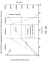
- the diagrams of the Fig. 4a and Fig. 4b represent the values for a second variant of the invention.
- the internal combustion engines are supported during takeoff and landing by expanding the use of the fuel cell system in order to achieve a reduction in the power requirements of the thermal engines (downsizing).
- controller 90 'secondary operating mode'.
- One advantage is that smaller internal combustion engines can be used. This results in a further increase in the emission-free flight share to approximately 70% (checkered area in Fig. 4a ).
- Line E (dashed): The power requirement of the propulsion system 10 over the mission with two hybrid-electric propulsion units 31, 32 to Fig. 4a is in principle the same as in Fig. 3a Here, too, the power requirement is highest during takeoff and decreases over the subsequent flight phases.
- Line F describes the flight altitude in ft over the duration of the mission.
- the flight altitude is highest during cruise flight and is, as with Fig. 3a about 25,000 ft
- Fig. 3a and Fig. 3b illustrate a key aspect of the invention: for many aircraft, particularly propeller-driven regional aircraft, the thrust required for takeoff is significantly higher than for cruising flight, meaning that the thermal engines are operated at only about half their capacity for a large portion of the flight mission. This means that conventional turboprop engines operate outside the optimal operating point, which is closer to the point of maximum power output. In contrast, a hybrid-electric propulsion system can be optimized for both different operating modes.
Landscapes
- Engineering & Computer Science (AREA)
- Aviation & Aerospace Engineering (AREA)
- Chemical & Material Sciences (AREA)
- Mechanical Engineering (AREA)
- Sustainable Development (AREA)
- Life Sciences & Earth Sciences (AREA)
- Sustainable Energy (AREA)
- Chemical Kinetics & Catalysis (AREA)
- General Chemical & Material Sciences (AREA)
- Manufacturing & Machinery (AREA)
- Electrochemistry (AREA)
- Combustion & Propulsion (AREA)
- General Engineering & Computer Science (AREA)
- Transportation (AREA)
- Power Engineering (AREA)
- Oil, Petroleum & Natural Gas (AREA)
- Electric Propulsion And Braking For Vehicles (AREA)
- Fuel Cell (AREA)
- Arrangement Or Mounting Of Propulsion Units For Vehicles (AREA)
Claims (15)
- Aéronef multimoteur possédant un système de propulsion hybride (10) avec• au moins une première unité de propulsion hybride électrique et une deuxième (31, 32), qui comportent chacune un moteur à combustion interne (41, 42), une unité de moteur et de générateur (71, 72) pour transmettre la puissance de propulsion à un propulseur (61, 62),• le propulseur (61, 62) pouvant être couplé avec le moteur à combustion interne (41, 42) et/ou avec l'unité de moteur et de générateur (71, 72) en vue de la transmission d'une puissance de propulsion,• les première et deuxième unités de moteur et de générateur (71, 72) étant reliées à une installation de transmission (80) en vue de la distribution de puissance électrique,• une pile à combustible (73) pour l'alimentation de la première et/ou de la deuxième unité de moteur et de générateur (71, 72) en énergie électrique,• un contrôleur (90) qui est connecté aux moteurs à combustion interne (41, 42) et/ou à l'unité de transmission (80) et/ou aux unités de moteur et de générateur (71, 72) et/ou à la pile à combustible (73) pour commander la puissance de propulsion générée de façon thermique ou électrique,• des réservoirs de combustible (43, 44) séparés pour l'alimentation des moteurs à combustion interne (41, 42) en carburant ou de la pile à combustible (73) en hydrogène cryogénique,• une aile portante (26) qui reçoit les unités de propulsion (31, 32) et un réservoir de combustible (43, 44), un fuselage (22),• l'unité de propulsion (31, 32) étant formée par un groupe turbopropulseur avec une turbine à gaz (41, 42) respective, qui peut être couplée à un engrenage (51, 52) pour l'entraînement d'une hélice (61, 62), et• l'unité de moteur et de générateur (71, 72) pouvant être couplée avec l'engrenage (51, 52) sous le contrôle du contrôleur (90) en fonction du mode de fonctionnement,caractérisé en ce que la majeure partie, au moins, du volume des réservoirs de combustible (43, 44) pour l'alimentation des moteurs à combustion interne (41, 42) est intégrée dans l'aile portante (26) et la majorité, au moins, du volume des réservoirs de combustible (74) pour l'alimentation de la pile à combustible (73) est intégrée dans une région arrière du fuselage (22).
- Aéronef multimoteur selon la revendication 1, caractérisé en ce que l'unité de propulsion hybride électrique (31, 32)• reçoit principalement ou entièrement la puissance de propulsion des moteurs à combustion interne (41, 42) dans un mode de fonctionnement primaire des propulseurs (61, 62),• dans un mode de fonctionnement mixte secondaire, les propulseurs (61, 62) reçoivent la puissance de propulsion des premier et deuxième moteurs à combustion interne (41, 42) et des première et deuxième unités de moteur et de générateur (71, 72) et• dans un troisième mode de fonctionnement, les propulseurs (61, 62) reçoivent la puissance de propulsion des première et deuxième unité de moteur et de générateur (71, 72).
- Aéronef multimoteur selon l'une des revendications précédentes, caractérisé en ce que le contrôleur (90) réalise une distribution symétrique de la puissance de propulsion aux propulseurs (61, 62) dans les modes de fonctionnement.
- Aéronef multimoteur selon l'une des revendications précédentes, caractérisé en ce que la puissance de propulsion électrique des première et deuxième unités de moteur et de générateur (71, 72) peut être appliquée de façon variable pendant la transition entre les modes de fonctionnement.
- Aéronef multimoteur selon l'une des revendications précédentes, caractérisé en ce que les unités de propulsion hybrides électriques (31, 32) comportent chacune un engrenage (51, 52) destiné à transmettre la puissance de propulsion, le moteur à combustion interne (41, 42) et l'unité de moteur et de générateur (71, 72) pouvant être couplés au propulseur (61, 62) au moyen de l'engrenage (51, 52).
- Aéronef multimoteur selon l'une des revendications précédentes, caractérisé en ce que le changement de transmission de la puissance de propulsion des moteurs à combustion interne (41, 42) et de la puissance de propulsion des unités de moteur et de générateur (71, 72) est effectué graduellement, de telle façon que la puissance de propulsion fournie au propulseur (61, 62) de l'unité de propulsion (31, 32) commune reste à peu près constante.
- Aéronef multimoteur selon l'une des revendications précédentes, caractérisé en ce que les propulseurs (61, 62) sont réalisés comme des hélices à pas variable et le contrôleur (90) est connecté au réglage du pas pour commander la puissance de propulsion.
- Aéronef multimoteur selon l'une des revendications précédentes, caractérisé en ce que, dans un autre mode de fonctionnement, la puissance de propulsion du premier ou deuxième moteur à combustion interne (41, 42) est complètement ou en majeure partie abolie et la première ou la deuxième unité de moteur et de générateur (71, 72) est alimentée en puissance électrique via l'unité de transmission (80) à partir de la pile à combustible (73).
- Aéronef multimoteur selon l'une des revendications précédentes, caractérisé en ce que l'unité de transmission (80) est réalisée comme un réseau de courant alternatif.
- Aéronef multimoteur selon l'une des revendications 1 à 9, caractérisé en ce que l'unité de transmission (80) est réalisée comme un réseau de courant continu, chaque unité de moteur et de générateur (71, 72) étant associée à un convertisseur alternatif-continu (81, 82) qui est connecté au contrôleur (90) pour commander la vitesse de rotation du propulseur (61, 62).
- Aéronef multimoteur selon l'une des revendications précédentes, caractérisé en ce que les moteurs à combustion interne (41, 42) fonctionnent avec du carburant d'aviation durable (SAF).
- Aéronef multimoteur selon l'une des revendications précédentes, caractérisé en ce qu'est prévu dans la partie arrière du fuselage (22) un espace pour la formation d'une soute de chargement dans laquelle est disposé le réservoir de combustible (74) destiné à alimenter la pile à combustible (73).
- Aéronef multimoteur selon l'une des revendications précédentes, caractérisé en ce que des groupes comprenant un contrôleur (90) et/ou une unité de transmission (80) et/ou une pile à combustible (73) sont disposés dans une partie avant du fuselage (22).
- Aéronef multimoteur selon la revendication 13, caractérisé en ce que les groupes et le réservoir de combustible (74) destiné à alimenter la pile à combustible (73) forment un équilibre de moments sensiblement neutre par rapport au centre de gravité (SP) de l'aéronef (20) et/ou
la pile à combustible (73) comporte une unité de refroidissement dont la chaleur dissipée sert à dégivrer des surfaces exposées de l'aéronef. - Procédé pour le fonctionnement d'un aéronef multimoteur (20) selon la revendication 2 ou selon une des revendications précédentes dépendant de la revendication 2, caractérisé en ce que le système de propulsion (10) est conduit dans des modes de fonctionnement primaire, secondaire, et un autre mode de fonctionnement, dans lesquels• le roulage de l'aéronef (20), en particulier sur les parkings et les taxiways, s'effectuent dans le mode de fonctionnement primaire ou le troisième,• le décollage et l'ascension jusqu'à l'altitude de croisière dans le mode de fonctionnement primaire ou secondaire,• le vol de croisière et la descente jusqu'à l'altitude d'approche dans le mode de fonctionnement secondaire ou le troisième,• l'approche et l'atterrissage dans le mode de fonctionnement primaire ou secondaire et• en cas de panne d'un moteur à combustion interne (41, 42), le vol se poursuit dans le mode de fonctionnement secondaire ou le troisième.
Applications Claiming Priority (2)
| Application Number | Priority Date | Filing Date | Title |
|---|---|---|---|
| DE102020126045.8A DE102020126045A1 (de) | 2020-10-05 | 2020-10-05 | Flugzeug mit einem Antriebs- und Energiesystem für emissionsarmen Reiseflug |
| PCT/DE2021/100772 WO2022073543A1 (fr) | 2020-10-05 | 2021-09-23 | Aéronef comprenant un système d'entraînement et d'énergie pour un vol de croisière à faibles émissions |
Publications (2)
| Publication Number | Publication Date |
|---|---|
| EP4225645A1 EP4225645A1 (fr) | 2023-08-16 |
| EP4225645B1 true EP4225645B1 (fr) | 2025-04-30 |
Family
ID=78080104
Family Applications (1)
| Application Number | Title | Priority Date | Filing Date |
|---|---|---|---|
| EP21786762.1A Active EP4225645B1 (fr) | 2020-10-05 | 2021-09-23 | Aéronef comprenant un système d'entraînement et d'énergie pour un vol de croisière à faibles émissions |
Country Status (6)
| Country | Link |
|---|---|
| US (1) | US20230348081A1 (fr) |
| EP (1) | EP4225645B1 (fr) |
| CN (1) | CN116261546A (fr) |
| CA (1) | CA3194908A1 (fr) |
| DE (2) | DE102020126045A1 (fr) |
| WO (1) | WO2022073543A1 (fr) |
Families Citing this family (17)
| Publication number | Priority date | Publication date | Assignee | Title |
|---|---|---|---|---|
| US11577846B2 (en) * | 2020-02-21 | 2023-02-14 | ZeroAvia, Inc. | Modular electric powertrain conversion for aircraft |
| WO2022245427A2 (fr) * | 2021-03-31 | 2022-11-24 | Zeroavia Ltd. | Système de ravitaillement en combustible pour aéronef à pile à combustible à hydrogène |
| US20220402621A1 (en) * | 2021-06-16 | 2022-12-22 | Happy Takeoff, Inc. | Power distribution control system and method for aircraft |
| EP4173956B1 (fr) * | 2021-10-29 | 2026-03-18 | Airbus S.A.S. | Système de propulsion hybride pour propulser un aéronef, son procédé de fonctionnement et aéronef hybride |
| WO2023074870A1 (fr) * | 2021-10-29 | 2023-05-04 | 川崎重工業株式会社 | Aéronef à hydrogène |
| US12091180B2 (en) * | 2021-12-20 | 2024-09-17 | The Boeing Company | Device and method for operating a hybrid-electric propulsion system by control of equipment dynamics |
| US20240034478A1 (en) * | 2022-07-27 | 2024-02-01 | Pratt & Whitney Canada Corp. | Multi-drive unit powerplant for an aircraft |
| DE102022128715A1 (de) * | 2022-10-28 | 2024-05-08 | MTU Aero Engines AG | Luftfahrzeug mit einem Brennstoffzellenantriebssystem |
| CN115892483A (zh) * | 2022-11-18 | 2023-04-04 | 中国商用飞机有限责任公司北京民用飞机技术研究中心 | 一种电推进系统能源架构及供能方法 |
| EP4442574B1 (fr) * | 2023-04-06 | 2025-04-02 | Coöperatie Elysian Aircraft Company U.A. | Principes de conception pour aéronef électrique |
| WO2024121080A1 (fr) * | 2022-12-08 | 2024-06-13 | Elysian Aircraft Company B.V. | Principes de conception pour aéronef électrique |
| CN116620554B (zh) * | 2023-05-17 | 2025-12-16 | 中国航发湖南动力机械研究所 | 一种燃氢混动涡桨发动机 |
| EP4477558B1 (fr) * | 2023-06-15 | 2026-03-11 | Airbus Operations, S.L.U. | Section de fuselage d'aéronef |
| US12110825B1 (en) * | 2023-08-29 | 2024-10-08 | General Electric Company | Systems and method for detecting and responding to icing conditions in gas turbine engines |
| DE102024103765A1 (de) * | 2024-02-09 | 2025-08-14 | MTU Aero Engines AG | Wärmetauscher-Tank-Anordnung für ein Flugzeug |
| CN117944911B (zh) * | 2024-03-21 | 2024-06-18 | 成都航空职业技术学院 | 一种氢燃气轮机无人机及其控制方法 |
| WO2025229474A1 (fr) | 2024-04-29 | 2025-11-06 | Deutsche Aircraft Gmbh | Aéronef à deux carburant avec réservoirs d'hydrogène intégrés |
Family Cites Families (14)
| Publication number | Priority date | Publication date | Assignee | Title |
|---|---|---|---|---|
| DE102006056355A1 (de) | 2006-11-29 | 2008-06-05 | Airbus Deutschland Gmbh | Antriebsvorrichtung zum Betrieb mit mehreren Kraftstoffen für ein Flugzeug |
| DE102006056354B4 (de) | 2006-11-29 | 2013-04-11 | Airbus Operations Gmbh | Hybridantrieb für ein Flugzeug |
| FR2931456B1 (fr) | 2008-05-26 | 2010-06-11 | Snecma | Aeronef a alimentation en energie hybride. |
| DE102009052047B4 (de) | 2009-11-05 | 2014-01-16 | Airbus Operations Gmbh | Regeleinheit und Verfahren zum Regeln der Versorgung eines Fahrzeugs mit mehreren Treibstoffen |
| DE102010021026A1 (de) | 2010-05-19 | 2011-11-24 | Eads Deutschland Gmbh | Hybrides Antriebs- und Energiesystem für Fluggeräte |
| DE102013209388B4 (de) | 2013-05-22 | 2021-07-22 | Robert Bosch Gmbh | Hybridantrieb für kraftgetriebenes Luftfahrzeug, kraftgetriebenes Luftfahrzeug mit Hybridantrieb und zugehöriges Betriebsverfahren |
| DE102014107316A1 (de) | 2014-05-23 | 2015-11-26 | Airbus Operations Gmbh | Tanksystem zur kryogenen Lagerung von Wasserstoff und Flugzeug mit einem Tanksystem zur kryogenen Lagerung von Wasserstoff |
| DE102014224637B4 (de) | 2014-12-02 | 2022-12-29 | Georgi Atanasov | Hybrid-Elektro-Antriebssystem für ein Flugzeug |
| WO2018175349A1 (fr) * | 2017-03-19 | 2018-09-27 | Zunum Aero, Inc. | Aéronef hybride-électrique, et procédés, appareil et systèmes destinés à faciliter ledit aéronef |
| US11008111B2 (en) | 2017-06-26 | 2021-05-18 | General Electric Company | Propulsion system for an aircraft |
| US11053019B2 (en) * | 2018-04-19 | 2021-07-06 | The Boeing Company | Hybrid propulsion engines for aircraft |
| US10981660B2 (en) * | 2018-04-19 | 2021-04-20 | The Boeing Company | Hybrid propulsion engines for aircraft |
| US10906657B2 (en) * | 2018-06-19 | 2021-02-02 | Raytheon Technologies Corporation | Aircraft system with distributed propulsion |
| US11414199B2 (en) * | 2019-03-01 | 2022-08-16 | Textron Innovations Inc. | Fuel cell powered line-replaceable thrust module |
-
2020
- 2020-10-05 DE DE102020126045.8A patent/DE102020126045A1/de not_active Ceased
-
2021
- 2021-09-23 DE DE112021005252.7T patent/DE112021005252A5/de active Pending
- 2021-09-23 WO PCT/DE2021/100772 patent/WO2022073543A1/fr not_active Ceased
- 2021-09-23 EP EP21786762.1A patent/EP4225645B1/fr active Active
- 2021-09-23 US US18/030,156 patent/US20230348081A1/en not_active Abandoned
- 2021-09-23 CN CN202180067960.8A patent/CN116261546A/zh active Pending
- 2021-09-23 CA CA3194908A patent/CA3194908A1/fr active Pending
Also Published As
| Publication number | Publication date |
|---|---|
| CA3194908A1 (fr) | 2022-04-14 |
| DE102020126045A1 (de) | 2022-04-07 |
| DE112021005252A5 (de) | 2023-08-24 |
| EP4225645A1 (fr) | 2023-08-16 |
| WO2022073543A1 (fr) | 2022-04-14 |
| CN116261546A (zh) | 2023-06-13 |
| US20230348081A1 (en) | 2023-11-02 |
Similar Documents
| Publication | Publication Date | Title |
|---|---|---|
| EP4225645B1 (fr) | Aéronef comprenant un système d'entraînement et d'énergie pour un vol de croisière à faibles émissions | |
| US20250206458A1 (en) | Hydrogen optimized aircraft architecture and operations | |
| DE102014224637B4 (de) | Hybrid-Elektro-Antriebssystem für ein Flugzeug | |
| de Vries et al. | A new perspective on battery-electric aviation, part II: Conceptual design of a 90-seater | |
| DE112014000391B4 (de) | Lärmarmes und hocheffizientes Flugzeug | |
| WO2022002319A1 (fr) | Système d'entraînement électrique hybride pour aéronefs multimoteurs | |
| EP3980637B1 (fr) | Aéronef à propulsion par hélice carénée | |
| DE102013015364A1 (de) | Angepasste Flugzeugkonfigurationen für die Energieeffiziente Open-Rotor Integration | |
| DE102019115577A1 (de) | Luftfahrzeug mit Antriebseinrichtung | |
| DE102012022288A1 (de) | Hybrid-elektrisches Antriebssystem, sowie Verfahren zum bodenbündigen Antrieb eines Flugzeuges mit niedriger bis hoher Geschwindigkeit | |
| Hartmann et al. | Conceptual Assessment of Different Hybrid Electric Air Vehicle Options for a Commuter with 19 Passengers | |
| DE102019218100A1 (de) | Wellenmechanisches Antriebssytem und -verfahren für ein Luftfahrzeug | |
| DE102022112111A1 (de) | Luftfahrzeug zum Fliegen in Umgebungsluft mit dynamischem Auftrieb | |
| WO2025229474A1 (fr) | Aéronef à deux carburant avec réservoirs d'hydrogène intégrés | |
| RU2819821C1 (ru) | Самолет | |
| DE102024111926A1 (de) | Antriebssystem insbesondere für mehrmotorige Fluggeräte, bevorzugt Flugzeuge | |
| DE102019130861B4 (de) | Strahltriebwerk mit impulsturbine | |
| DE102023110825A1 (de) | Selektiv bodengebundene flexible Schubkrafterzeugung | |
| Kusmierek et al. | Gali nski, C. Analysis Leading to the Design of a Hybrid Gas-Electric Multi-Engine Testbed. Aerospace 2023, 10, 998 | |
| Eissele et al. | FUTPRINT50 Academy–Aircraft Design Challenge 2022: Development of a hybrid-electric regional aircraft | |
| de Vries et al. | Conceptual Redesign of a 90-Seater Battery-Electric Aircraft | |
| Li et al. | Feasibility study of an electric propulsion transport category aircraft | |
| DE202015006442U1 (de) | Hybridantrieb für Segelflugzeuge | |
| DE102018222543A1 (de) | Flugzeug mit hybrid-elektrischem Antrieb und Verfahren zum Betreiben eines solchen Flugzeugs | |
| Gill et al. | Rotorcraft convertible engine study |
Legal Events
| Date | Code | Title | Description |
|---|---|---|---|
| STAA | Information on the status of an ep patent application or granted ep patent |
Free format text: STATUS: UNKNOWN |
|
| STAA | Information on the status of an ep patent application or granted ep patent |
Free format text: STATUS: THE INTERNATIONAL PUBLICATION HAS BEEN MADE |
|
| PUAI | Public reference made under article 153(3) epc to a published international application that has entered the european phase |
Free format text: ORIGINAL CODE: 0009012 |
|
| STAA | Information on the status of an ep patent application or granted ep patent |
Free format text: STATUS: REQUEST FOR EXAMINATION WAS MADE |
|
| 17P | Request for examination filed |
Effective date: 20230404 |
|
| AK | Designated contracting states |
Kind code of ref document: A1 Designated state(s): AL AT BE BG CH CY CZ DE DK EE ES FI FR GB GR HR HU IE IS IT LI LT LU LV MC MK MT NL NO PL PT RO RS SE SI SK SM TR |
|
| DAV | Request for validation of the european patent (deleted) | ||
| DAX | Request for extension of the european patent (deleted) | ||
| REG | Reference to a national code |
Ref country code: HK Ref legal event code: DE Ref document number: 40098167 Country of ref document: HK |
|
| GRAP | Despatch of communication of intention to grant a patent |
Free format text: ORIGINAL CODE: EPIDOSNIGR1 |
|
| STAA | Information on the status of an ep patent application or granted ep patent |
Free format text: STATUS: GRANT OF PATENT IS INTENDED |
|
| INTG | Intention to grant announced |
Effective date: 20241127 |
|
| GRAS | Grant fee paid |
Free format text: ORIGINAL CODE: EPIDOSNIGR3 |
|
| GRAA | (expected) grant |
Free format text: ORIGINAL CODE: 0009210 |
|
| STAA | Information on the status of an ep patent application or granted ep patent |
Free format text: STATUS: THE PATENT HAS BEEN GRANTED |
|
| RAP3 | Party data changed (applicant data changed or rights of an application transferred) |
Owner name: DEUTSCHE AIRCRAFT GMBH |
|
| AK | Designated contracting states |
Kind code of ref document: B1 Designated state(s): AL AT BE BG CH CY CZ DE DK EE ES FI FR GB GR HR HU IE IS IT LI LT LU LV MC MK MT NL NO PL PT RO RS SE SI SK SM TR |
|
| REG | Reference to a national code |
Ref country code: CH Ref legal event code: EP Ref country code: GB Ref legal event code: FG4D Free format text: NOT ENGLISH |
|
| REG | Reference to a national code |
Ref country code: DE Ref legal event code: R096 Ref document number: 502021007362 Country of ref document: DE |
|
| REG | Reference to a national code |
Ref country code: IE Ref legal event code: FG4D Free format text: LANGUAGE OF EP DOCUMENT: GERMAN |
|
| P01 | Opt-out of the competence of the unified patent court (upc) registered |
Free format text: CASE NUMBER: APP_21820/2025 Effective date: 20250507 |
|
| REG | Reference to a national code |
Ref country code: NL Ref legal event code: MP Effective date: 20250430 |
|
| PG25 | Lapsed in a contracting state [announced via postgrant information from national office to epo] |
Ref country code: FI Free format text: LAPSE BECAUSE OF FAILURE TO SUBMIT A TRANSLATION OF THE DESCRIPTION OR TO PAY THE FEE WITHIN THE PRESCRIBED TIME-LIMIT Effective date: 20250430 Ref country code: PT Free format text: LAPSE BECAUSE OF FAILURE TO SUBMIT A TRANSLATION OF THE DESCRIPTION OR TO PAY THE FEE WITHIN THE PRESCRIBED TIME-LIMIT Effective date: 20250901 Ref country code: ES Free format text: LAPSE BECAUSE OF FAILURE TO SUBMIT A TRANSLATION OF THE DESCRIPTION OR TO PAY THE FEE WITHIN THE PRESCRIBED TIME-LIMIT Effective date: 20250430 |
|
| PGFP | Annual fee paid to national office [announced via postgrant information from national office to epo] |
Ref country code: DE Payment date: 20250919 Year of fee payment: 5 |
|
| REG | Reference to a national code |
Ref country code: LT Ref legal event code: MG9D |
|
| PG25 | Lapsed in a contracting state [announced via postgrant information from national office to epo] |
Ref country code: GR Free format text: LAPSE BECAUSE OF FAILURE TO SUBMIT A TRANSLATION OF THE DESCRIPTION OR TO PAY THE FEE WITHIN THE PRESCRIBED TIME-LIMIT Effective date: 20250731 Ref country code: NO Free format text: LAPSE BECAUSE OF FAILURE TO SUBMIT A TRANSLATION OF THE DESCRIPTION OR TO PAY THE FEE WITHIN THE PRESCRIBED TIME-LIMIT Effective date: 20250730 |
|
| PG25 | Lapsed in a contracting state [announced via postgrant information from national office to epo] |
Ref country code: NL Free format text: LAPSE BECAUSE OF FAILURE TO SUBMIT A TRANSLATION OF THE DESCRIPTION OR TO PAY THE FEE WITHIN THE PRESCRIBED TIME-LIMIT Effective date: 20250430 Ref country code: PL Free format text: LAPSE BECAUSE OF FAILURE TO SUBMIT A TRANSLATION OF THE DESCRIPTION OR TO PAY THE FEE WITHIN THE PRESCRIBED TIME-LIMIT Effective date: 20250430 |
|
| PG25 | Lapsed in a contracting state [announced via postgrant information from national office to epo] |
Ref country code: BG Free format text: LAPSE BECAUSE OF FAILURE TO SUBMIT A TRANSLATION OF THE DESCRIPTION OR TO PAY THE FEE WITHIN THE PRESCRIBED TIME-LIMIT Effective date: 20250430 |
|
| PGFP | Annual fee paid to national office [announced via postgrant information from national office to epo] |
Ref country code: GB Payment date: 20250923 Year of fee payment: 5 |
|
| PG25 | Lapsed in a contracting state [announced via postgrant information from national office to epo] |
Ref country code: HR Free format text: LAPSE BECAUSE OF FAILURE TO SUBMIT A TRANSLATION OF THE DESCRIPTION OR TO PAY THE FEE WITHIN THE PRESCRIBED TIME-LIMIT Effective date: 20250430 |
|
| PGFP | Annual fee paid to national office [announced via postgrant information from national office to epo] |
Ref country code: AT Payment date: 20251020 Year of fee payment: 5 Ref country code: FR Payment date: 20250924 Year of fee payment: 5 |
|
| PG25 | Lapsed in a contracting state [announced via postgrant information from national office to epo] |
Ref country code: RS Free format text: LAPSE BECAUSE OF FAILURE TO SUBMIT A TRANSLATION OF THE DESCRIPTION OR TO PAY THE FEE WITHIN THE PRESCRIBED TIME-LIMIT Effective date: 20250731 |
|
| PG25 | Lapsed in a contracting state [announced via postgrant information from national office to epo] |
Ref country code: IS Free format text: LAPSE BECAUSE OF FAILURE TO SUBMIT A TRANSLATION OF THE DESCRIPTION OR TO PAY THE FEE WITHIN THE PRESCRIBED TIME-LIMIT Effective date: 20250830 |
|
| PG25 | Lapsed in a contracting state [announced via postgrant information from national office to epo] |
Ref country code: LV Free format text: LAPSE BECAUSE OF FAILURE TO SUBMIT A TRANSLATION OF THE DESCRIPTION OR TO PAY THE FEE WITHIN THE PRESCRIBED TIME-LIMIT Effective date: 20250430 |
|
| PG25 | Lapsed in a contracting state [announced via postgrant information from national office to epo] |
Ref country code: DK Free format text: LAPSE BECAUSE OF FAILURE TO SUBMIT A TRANSLATION OF THE DESCRIPTION OR TO PAY THE FEE WITHIN THE PRESCRIBED TIME-LIMIT Effective date: 20250430 Ref country code: SM Free format text: LAPSE BECAUSE OF FAILURE TO SUBMIT A TRANSLATION OF THE DESCRIPTION OR TO PAY THE FEE WITHIN THE PRESCRIBED TIME-LIMIT Effective date: 20250430 |
|
| PG25 | Lapsed in a contracting state [announced via postgrant information from national office to epo] |
Ref country code: CZ Free format text: LAPSE BECAUSE OF FAILURE TO SUBMIT A TRANSLATION OF THE DESCRIPTION OR TO PAY THE FEE WITHIN THE PRESCRIBED TIME-LIMIT Effective date: 20250430 |
|
| PG25 | Lapsed in a contracting state [announced via postgrant information from national office to epo] |
Ref country code: EE Free format text: LAPSE BECAUSE OF FAILURE TO SUBMIT A TRANSLATION OF THE DESCRIPTION OR TO PAY THE FEE WITHIN THE PRESCRIBED TIME-LIMIT Effective date: 20250430 |
|
| PG25 | Lapsed in a contracting state [announced via postgrant information from national office to epo] |
Ref country code: SK Free format text: LAPSE BECAUSE OF FAILURE TO SUBMIT A TRANSLATION OF THE DESCRIPTION OR TO PAY THE FEE WITHIN THE PRESCRIBED TIME-LIMIT Effective date: 20250430 |
|
| PG25 | Lapsed in a contracting state [announced via postgrant information from national office to epo] |
Ref country code: IT Free format text: LAPSE BECAUSE OF FAILURE TO SUBMIT A TRANSLATION OF THE DESCRIPTION OR TO PAY THE FEE WITHIN THE PRESCRIBED TIME-LIMIT Effective date: 20250430 |
|
| REG | Reference to a national code |
Ref country code: DE Ref legal event code: R097 Ref document number: 502021007362 Country of ref document: DE |
|
| PG25 | Lapsed in a contracting state [announced via postgrant information from national office to epo] |
Ref country code: RO Free format text: LAPSE BECAUSE OF FAILURE TO SUBMIT A TRANSLATION OF THE DESCRIPTION OR TO PAY THE FEE WITHIN THE PRESCRIBED TIME-LIMIT Effective date: 20250430 |
|
| PLBE | No opposition filed within time limit |
Free format text: ORIGINAL CODE: 0009261 |
|
| STAA | Information on the status of an ep patent application or granted ep patent |
Free format text: STATUS: NO OPPOSITION FILED WITHIN TIME LIMIT |
|
| REG | Reference to a national code |
Ref country code: CH Ref legal event code: L10 Free format text: ST27 STATUS EVENT CODE: U-0-0-L10-L00 (AS PROVIDED BY THE NATIONAL OFFICE) Effective date: 20260311 |
|
| 26N | No opposition filed |
Effective date: 20260202 |