EP4225701B1 - Appareil de traitement d'eaux usées - Google Patents
Appareil de traitement d'eaux usées Download PDFInfo
- Publication number
- EP4225701B1 EP4225701B1 EP21785823.2A EP21785823A EP4225701B1 EP 4225701 B1 EP4225701 B1 EP 4225701B1 EP 21785823 A EP21785823 A EP 21785823A EP 4225701 B1 EP4225701 B1 EP 4225701B1
- Authority
- EP
- European Patent Office
- Prior art keywords
- settling tank
- tank
- waste water
- sediment
- collection
- Prior art date
- Legal status (The legal status is an assumption and is not a legal conclusion. Google has not performed a legal analysis and makes no representation as to the accuracy of the status listed.)
- Active
Links
Images

Classifications
-
- B—PERFORMING OPERATIONS; TRANSPORTING
- B01—PHYSICAL OR CHEMICAL PROCESSES OR APPARATUS IN GENERAL
- B01D—SEPARATION
- B01D17/00—Separation of liquids, not provided for elsewhere, e.g. by thermal diffusion
- B01D17/02—Separation of non-miscible liquids
- B01D17/0208—Separation of non-miscible liquids by sedimentation
- B01D17/0211—Separation of non-miscible liquids by sedimentation with baffles
-
- B—PERFORMING OPERATIONS; TRANSPORTING
- B01—PHYSICAL OR CHEMICAL PROCESSES OR APPARATUS IN GENERAL
- B01D—SEPARATION
- B01D21/00—Separation of suspended solid particles from liquids by sedimentation
- B01D21/003—Sedimentation tanks provided with a plurality of compartments separated by a partition wall
- B01D21/0036—Horizontal partition walls
-
- B—PERFORMING OPERATIONS; TRANSPORTING
- B01—PHYSICAL OR CHEMICAL PROCESSES OR APPARATUS IN GENERAL
- B01D—SEPARATION
- B01D21/00—Separation of suspended solid particles from liquids by sedimentation
- B01D21/0039—Settling tanks provided with contact surfaces, e.g. baffles, particles
- B01D21/0042—Baffles or guide plates
-
- B—PERFORMING OPERATIONS; TRANSPORTING
- B01—PHYSICAL OR CHEMICAL PROCESSES OR APPARATUS IN GENERAL
- B01D—SEPARATION
- B01D21/00—Separation of suspended solid particles from liquids by sedimentation
- B01D21/24—Feed or discharge mechanisms for settling tanks
- B01D21/2433—Discharge mechanisms for floating particles
-
- B—PERFORMING OPERATIONS; TRANSPORTING
- B01—PHYSICAL OR CHEMICAL PROCESSES OR APPARATUS IN GENERAL
- B01D—SEPARATION
- B01D21/00—Separation of suspended solid particles from liquids by sedimentation
- B01D21/24—Feed or discharge mechanisms for settling tanks
- B01D21/2433—Discharge mechanisms for floating particles
- B01D21/2438—Discharge mechanisms for floating particles provided with scrapers on the liquid surface for removing floating particles
-
- B—PERFORMING OPERATIONS; TRANSPORTING
- B01—PHYSICAL OR CHEMICAL PROCESSES OR APPARATUS IN GENERAL
- B01D—SEPARATION
- B01D21/00—Separation of suspended solid particles from liquids by sedimentation
- B01D21/24—Feed or discharge mechanisms for settling tanks
- B01D21/2444—Discharge mechanisms for the classified liquid
-
- B—PERFORMING OPERATIONS; TRANSPORTING
- B01—PHYSICAL OR CHEMICAL PROCESSES OR APPARATUS IN GENERAL
- B01D—SEPARATION
- B01D21/00—Separation of suspended solid particles from liquids by sedimentation
- B01D21/24—Feed or discharge mechanisms for settling tanks
- B01D21/245—Discharge mechanisms for the sediments
-
- B—PERFORMING OPERATIONS; TRANSPORTING
- B01—PHYSICAL OR CHEMICAL PROCESSES OR APPARATUS IN GENERAL
- B01D—SEPARATION
- B01D21/00—Separation of suspended solid particles from liquids by sedimentation
- B01D21/30—Control equipment
-
- C—CHEMISTRY; METALLURGY
- C02—TREATMENT OF WATER, WASTE WATER, SEWAGE, OR SLUDGE
- C02F—TREATMENT OF WATER, WASTE WATER, SEWAGE, OR SLUDGE
- C02F1/00—Treatment of water, waste water, or sewage
- C02F1/001—Processes for the treatment of water whereby the filtration technique is of importance
-
- C—CHEMISTRY; METALLURGY
- C02—TREATMENT OF WATER, WASTE WATER, SEWAGE, OR SLUDGE
- C02F—TREATMENT OF WATER, WASTE WATER, SEWAGE, OR SLUDGE
- C02F1/00—Treatment of water, waste water, or sewage
- C02F1/40—Devices for separating or removing fatty or oily substances or similar floating material
-
- E—FIXED CONSTRUCTIONS
- E03—WATER SUPPLY; SEWERAGE
- E03F—SEWERS; CESSPOOLS
- E03F5/00—Sewerage structures
- E03F5/14—Devices for separating liquid or solid substances from sewage, e.g. sand or sludge traps, rakes or grates
- E03F5/16—Devices for separating oil, water or grease from sewage in drains leading to the main sewer
-
- C—CHEMISTRY; METALLURGY
- C02—TREATMENT OF WATER, WASTE WATER, SEWAGE, OR SLUDGE
- C02F—TREATMENT OF WATER, WASTE WATER, SEWAGE, OR SLUDGE
- C02F1/00—Treatment of water, waste water, or sewage
- C02F2001/007—Processes including a sedimentation step
-
- C—CHEMISTRY; METALLURGY
- C02—TREATMENT OF WATER, WASTE WATER, SEWAGE, OR SLUDGE
- C02F—TREATMENT OF WATER, WASTE WATER, SEWAGE, OR SLUDGE
- C02F2101/00—Nature of the contaminant
- C02F2101/30—Organic compounds
- C02F2101/32—Hydrocarbons, e.g. oil
-
- C—CHEMISTRY; METALLURGY
- C02—TREATMENT OF WATER, WASTE WATER, SEWAGE, OR SLUDGE
- C02F—TREATMENT OF WATER, WASTE WATER, SEWAGE, OR SLUDGE
- C02F2103/00—Nature of the water, waste water, sewage or sludge to be treated
- C02F2103/32—Nature of the water, waste water, sewage or sludge to be treated from the food or foodstuff industry, e.g. brewery waste waters
-
- C—CHEMISTRY; METALLURGY
- C02—TREATMENT OF WATER, WASTE WATER, SEWAGE, OR SLUDGE
- C02F—TREATMENT OF WATER, WASTE WATER, SEWAGE, OR SLUDGE
- C02F2209/00—Controlling or monitoring parameters in water treatment
- C02F2209/005—Processes using a programmable logic controller [PLC]
- C02F2209/008—Processes using a programmable logic controller [PLC] comprising telecommunication features, e.g. modems or antennas
-
- C—CHEMISTRY; METALLURGY
- C02—TREATMENT OF WATER, WASTE WATER, SEWAGE, OR SLUDGE
- C02F—TREATMENT OF WATER, WASTE WATER, SEWAGE, OR SLUDGE
- C02F2209/00—Controlling or monitoring parameters in water treatment
- C02F2209/02—Temperature
-
- C—CHEMISTRY; METALLURGY
- C02—TREATMENT OF WATER, WASTE WATER, SEWAGE, OR SLUDGE
- C02F—TREATMENT OF WATER, WASTE WATER, SEWAGE, OR SLUDGE
- C02F2209/00—Controlling or monitoring parameters in water treatment
- C02F2209/11—Turbidity
-
- C—CHEMISTRY; METALLURGY
- C02—TREATMENT OF WATER, WASTE WATER, SEWAGE, OR SLUDGE
- C02F—TREATMENT OF WATER, WASTE WATER, SEWAGE, OR SLUDGE
- C02F2209/00—Controlling or monitoring parameters in water treatment
- C02F2209/22—O2
-
- C—CHEMISTRY; METALLURGY
- C02—TREATMENT OF WATER, WASTE WATER, SEWAGE, OR SLUDGE
- C02F—TREATMENT OF WATER, WASTE WATER, SEWAGE, OR SLUDGE
- C02F2209/00—Controlling or monitoring parameters in water treatment
- C02F2209/42—Liquid level
Definitions
- This invention relates to a waste water treatment apparatus, and more especially to a waste water treatment apparatus for removing fats, oils and grease and solid waste from waste water, for example from a sink in a commercial kitchen.
- waste water drained from a sink in a commercial kitchen or catering facility contains grease in an emulsified state, as well as grease laden solids in suspension, typically in the form of foods wastes, as well as other solid waste.
- Such contaminants can cause blockages in drainage systems and/or fouling of filtration systems or pumps within water treatment plants downstream of the drainage system.
- Effluent from FOG contamination points in commercial kitchens typically originates from steam combination ovens, convection rotisserie ovens, pot sinks, pre-rinse sinks, dishwashers, canopies and the like. They have in common the use and application of hot water ranging in temperature from 40° C to 85° C for the purposes of dealing with FOG contamination, where FOG is washed away in the waste water stream from such devices.
- Known grease traps range in complexity from simple settling tanks, known as “passive” grease traps, that require periodic manual grease removal, to rather complex structural arrangements that provide for automatic skimming and collection of skimmed fats, oils and grease into external containers positioned adjacent the trap assembly, commonly referred to as “automated” grease traps or GRUs.
- Passive grease traps are, in essence, simply a settling tank having a wastewater inlet at one end and an outlet at an opposite end for connection to a drain. Often baffle plates are arranged within the tank to interrupt direct flow-through of wastewater between the inlet and the outlet. Periodically, an employee must manually skim the FOG that has accumulated at the surface of the wastewater.
- Automated grease traps include automatic skimmer arrangements, typically utilising a skimmer device, in the form of a disc, drum, endless belt or tube, mounted above the tank and connected to a drive arrangement to move the skimming device through the layer of FOG floating on the waste water within the tank of the grease trap.
- the skimming device collects FOG from the surface of the water in the tank and is subsequently cleaned by means providing a scraping or squeezing action on the skimming device, such as wiper blades, arranged to direct the collected FOG into a collection device before the skimming device passes back into the water.
- the collection device is typically a separate container or reservoir located on one side of the tank.
- While skimmer devices may continuously remove FOG from the surface of the water in the tank, food waste and other solids material carried in the waste water collects in the bottom of the tank as organic sediment. If this is not attended to, indigenous mesophilic bacteria will deplete the dissolved oxygen in the effluent leading to offensive malodours in commercial kitchens and unpleasant working conditions for staff and may require frequent decommissioning of the tank for removal of the sediment.
- a bottom wall of the settling tank slopes downwardly towards the sediment collection region and towards an inlet end of the extraction passage within the settling tank to encourage sediment to move towards the inlet end of the extraction passage.
- the sediment removal pump may be adapted to pump sediment from the settling tank, as a slurry, into the drain of the settling tank or, alternatively, into a separate collection vessel or drain outlet.
- the settling tank comprises first and second oppositely disposed end walls spaced apart by first and second oppositely disposed side walls, a longitudinal baffle or dividing wall extending inwardly from said first end wall towards said second end wall, parallel to said first and second side walls, said dividing wall terminating adjacent said second end wall such that the dividing wall divides the interior of the settling tank into an inlet region and a settlement region, said skimming device and said sediment removal system being associated with said settlement region.
- the dividing wall may be positioned adjacent the first side wall of the tank such that the inlet region of the tank is narrower than the settlement region.
- a pair of parallel vertically arranged baffle plates extend across the width of the settlement region of the settling tank between the dividing wall and the second side wall of the settling tank, the baffle plates having lower edges terminating above the bottom wall of the settling tank and upper edges extending above the normal water level in the settling tank, the baffle plates being spaced apart from one another to define a cavity therebetween, wherein the inlet end of the sediment extraction passage extends into said cavity through one of said baffle plates such that said cavity defines an inlet region of the sediment extraction passage.
- Said cavity may serve as a vent for the sediment removal pump.
- the sediment extraction passage is defined by a pipe extending from the sediment removal pump into the settling tank and terminating in said cavity. An inlet end of the sediment extraction pipe extends into said cavity through one of said baffle plates.
- the drain of the settling tank extends from a rear wall of the housing.
- a waste water collection tank may be mounted within the housing adjacent the settling tank serving as a solid waste interceptor, a food waste collection tray being located within the waste water collection tank for collecting solid waste therein.
- a removable strainer basket may be mounted within the food waste collection tray for collecting food waste and other solid waste therein, the strainer basket incorporating apertures or slots, such that waste water can pass through the strainer basket, while solid waste entrained within the waste water is collected within the strainer basket.
- Waste water, containing FOG and entrained food waste and other solids, for example from a sink drain may be fed into the strainer basket in the waste water collection tank via an inlet pipe feeding through feed holes in a rear wall of the tray and rear wall of the basket.
- a bottom wall of the food waste collection tray may be perforated to allow water to drain therethrough into the waste water collection tank.
- a bottom wall of the waste water collection tank may incorporate a drain gulley at the lowermost point thereof, leading into a downwardly sloping supply channel communicating with the settling tank.
- a further strainer may be provided between the waste water collection tank and the supply channel, further strainer preferably comprising a perforated section of the bottom wall of the food waste collection tray through which waste water must pass to reach the supply channel.
- the skimming device may comprise an elongate drum having a surface coated with or formed from a hydrophobic and oleophilic material, the drum being mounted in the settling tank to be partially submerged in waste water held in the tank when in use, the drum being mounted in the tank to be rotatable, under the action of a motor.
- a FOG collection tank may be mounted on one side of the housing adjacent the skimming device and includes a scraper or wiper blade arranged to engage the surface of the drum of the skimming device to scrape FOG from the surface thereof and deliver the FOG into the collection tank.
- One or more sensors may be associated with the settling tank adapted to measure one or more of the dissolved oxygen-n content of the water in the settling tank, the level of settled out FOG on top of the water in the settling tank, the temperature of the water in the settling tank and the turbidity of the water.
- Said one or more sensors may comprise non-contact sensors that are not in direct contact with the waste water. Data from said one or more sensors may be transmitted via a wired or wireless communication means to a central monitoring and/or control centre, to facilitate monitoring and management of the apparatus or of multiple installations.
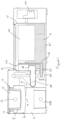
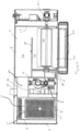
- a waste water treatment apparatus in accordance with an embodiment of the present invention comprises a substantially rectangular housing 2 having a settling tank 4 mounted therein to define a grease trap wherein FOG separated from the waste water to float on the surface of the waste water before being is removed before the water is passed to a drain, thereby greatly reducing the passage of FOG into the drain.
- a waste water collection tank 6 is located within the housing adjacent the settling tank 4 serving as a solid waste interceptor.
- a food waste collection tray 8 is located within the waste water collection tank 6, a strainer basket 10 being mounted within the tray 8 for collecting food waste and other solid waste therein. Waste water, containing FOG and entrained food waste and other solids, for example from a sink drain, may be fed into the strainer basket in the waste water collection tank 8 via the inlet pipe 12 feeding through feed holes in a rear wall of the tray 8 and rear wall of the basket 10.
- the food waste collection tray 8 is slidably mounted within the waste water collection tank 6 in the manner of a drawer, the tray 8 being adapted to be slid laterally into and out of a front side of the waste water collection tank 6 between a closed position, wherein the strainer basket 10 receives waste water from the waste water inlet pipe 12, and an open position, wherein the tray 8 extends laterally from the front of the tank 2 to provide access to the strainer basket 10 to permit removal of the strainer basket 10 for emptying collected food waste therefrom.
- Runners 14 ( Figure 4) may be provided on the inner faces of the side walls of the tank 2 upon which the tray 8 may be supported and guided.
- a spare strainer basket 10B is stored in the space below the waste water collection tank 8.
- a bottom wall of the food waste collection tray 8 may be perforated to allow water to drain therethrough into the waste water collection tank 6, whereby further solid waste is intercepted in the collection tray 8.
- a bottom wall of the waste water collection tank 6 incorporates a central gulley 15 at the lowermost point thereof, extending parallel to side walls of the tank 6, the floor of the tank 6 preferably depending downwardly on either side of the gulley 15 to facilitate the drainage of waste water into the gully 15.
- the gulley 15 leads into a downwardly sloping supply channel 21 communicating with the settling tank 4.
- the supply channel 21 reduces the velocity and turbulence of the waste water before it reaches the settling tank 4 to increase retention and removal efficiency.
- a further strainer for example a perforated section 9 of the bottom wall of the tray 8 through which waste water must pass to reach the supply channel 21, may be provided between the waste water collection tank 6 and the supply channel 21 to trap solid waste without allowing it to pass to the settling tank 4, for example should the waste water pass into the waste water collection tank 6 with the food waste collection tray 8 open.
- the settling tank 4 comprises first and second oppositely disposed end walls 16,17 spaced apart by first and second oppositely disposed side walls 18,19.
- a longitudinal baffle or dividing wall 20 extends inwardly from said first end wall 16 towards said second end wall 17, parallel to said first and second side walls 18,19, said dividing wall 20 terminating adjacent said second end wall 17.
- the dividing wall 20 divides the interior of the settling tank 4 into an inlet region 22 and a settlement region 24.
- the dividing wall 20 is positioned adjacent the first side wall 18 of the tank such that the inlet region 22 of the tank 8 is narrower than the settlement region 24.
- the dividing wall 20 defines a flow path for the waste water through the settling tank 4 and effectively doubles the traverse length of the waste water through the tank 4.
- the change of direction forced upon the waste water as it passes through the tank 4 also slows the flow of waste water, encouraging the separation of the FOG and water in the settlement region 24 of the settling tank 4.
- a water drain 26 is provided in a downstream end of the settlement region 24 of the settling tank 4, an inlet end of the drain 26 being defined by a weir 28 which controls the water level within the settling tank 4, cleaned water overflowing the weir 28 to pass out of the tank 4 via the drain 26, an outlet end 30 of the drain 26 extending from a rear wall of the housing 2.
- a skimming device is mounted in the settlement region 24 of the settling tank 4.
- the skimming device comprises an elongate drum 40 having a surface coated with or formed from a hydrophobic and oleophilic material, the drum 40 being mounted in the settlement region 24 of the settling tank 4 to be partially submerged in waste water held in the tank 4 when in use.
- the drum 54 is mounted in the tank 4 to be rotatable, under the action of a motor 56, to rotate about an axis extending substantially parallel to the first and second sides 16,17 of the settling tank 4.
- a FOG collection tank 50 is mounted on one side of the 2 housing adjacent the second side 17 of the settling tank 4 adjacent the skimming device and includes a scraper or wiper blade 52 arranged to engage the surface of the drum 40 to scrape FOG from the surface thereof and deliver the FOG into the collection tank 50.
- the wiper blade 52 is mounted on an extension of one side of the FOG collection tank 50 such that the wiper blade 52 is brought into contact with the drum 40 as the FOG collection tank 50 is mounted onto the side of the housing 2.
- the FOG collection tank 50 is removed to permit emptying the wiper blade 52 can be cleaned at the same time.
- the settling tank 4 is provided with a sediment removal system, whereby sediment collected in the bottom of the tank can be automatically removed to enhance the efficiency of the apparatus, as will be described below in more detail.
- sediment primarily comprising food waste having a specific gravity greater than 1, would have to had been manually removed during periodic maintenance of the grease trap.
- a sediment removal pump 60 is located in the housing 2 adjacent the first end 16 of the settling tank 4.
- An inlet of the pump 60 is coupled to a sediment extraction pipe 62 extending horizontally into a sediment collection region in the settling tank 4 and adapted to draw sediment accumulated in the sediment collection region in the bottom/lowest point of the settlement region 24 of the settling tank 4.
- the bottom wall 61 of the settlement region 24 of the settling tank 4 preferably slopes downwardly from the second end wall 17 towards the first end wall 16, towards an inlet end of the extraction pipe 62, to encourage sediment to move towards the extraction pipe 62.
- the sediment removal pump 60 may pump the sediment collected in the sediment collection region, in the form of a thick slurry, from the settling tank and into the drain 26 or, alternatively, into a separate collection vessel or drain outlet.
- a pair of parallel vertically arranged baffle plates 64,66 extend across the width of the settlement region 24 of the settling tank 4 between the dividing wall 20 and the second side wall 19 of the tank 4, the baffle plates 64,66 having lower edges terminating above the bottom wall of the settling tank 4 and upper edges extending above the normal water level in the settling tank.
- the baffle plates 64,66 are space apart to define a relatively narrow (preferably around 10mm) cavity therebetween, said cavity serving as a vent for the sediment removal pump and also an inlet region for the sediment extraction pipe 62, with the inlet end of the sediment extraction pipe 62 extending into said cavity through one of said baffle plates and sediment passing between the lower ends of the baffle plates 64,66 to pass into the extraction pipe 62.
- the baffle plates 64,66 also maximise the removal of sediment by ensuring that the sediment removal pump 60 only draws slurry from the sediment collection region in the lowest point of the settling tank 4.
- the relatively narrow cavity defined between the baffle plates 64,66 may create a venturi effect, increasing the flow velocity at the inlet end of the extraction pipe 62, thereby enhancing sediment extraction.
- a programmable controller is preferably provided for controlling the operation of the skimming device and the sediment removal pump.
- the controller may include a timer to permit the skimming device and sediment removal pump to be periodically operated at pre-programmed times and for predetermined periods.
- the controller may receive inputs from a plurality of sensors associated with the settling tank, for example for measuring one or more of the dissolved oxygen content of the water in the settling tank, the level of settled out FOG on top of the water in the settling tank, the temperature of the water in the settling tank and the turbidity of the water.
- a plurality of sensors associated with the settling tank for example for measuring one or more of the dissolved oxygen content of the water in the settling tank, the level of settled out FOG on top of the water in the settling tank, the temperature of the water in the settling tank and the turbidity of the water.
- non-contact sensors are used.
- Data from said sensors may be transmitted via a wired or wireless communication means, for example via the Internet, to a central monitoring and/or control centre, to facilitate monitoring and management of the apparatus or of multiple installations.
- the data collected may be used to ensure correct operation and use of the apparatus.
- a waste water treatment apparatus in accordance with the present invention can protect the drainage and water course systems.
- the use of the apparatus in accordance with the present invention may prevent blockages of FOG origin in drains and protects pumping stations whilst significantly reducing the loading on waste water treatment plants.
- significant effluent treatment charges can be applied as a result of high BOD, SS and FOG levels detected.
- a waste water treatment apparatus in accordance with the present invention can achieve significant reductions in the BOD; COD: FOG and SS loading levels of effluent being discharged from commercial food service premises.
- the waste water treatment apparatus in accordance with the present invention can take advantage of waste thermal energy present in effluent being discharged from commercial kitchens to remove emulsified FOG, particularly saturated animal fats before they solidify. No heating elements are used thereby reducing energy and operational costs and CO2 related emissions. This has been quantified as approximating to a saving of up to 5 tonnes of CO2 related emissions in a year in comparison to passive traps and mechanical grease traps which utilise heating elements and which traps require to be pumped on a regular basis involving the use of road tankers.
Landscapes
- Chemical & Material Sciences (AREA)
- Chemical Kinetics & Catalysis (AREA)
- Water Supply & Treatment (AREA)
- Hydrology & Water Resources (AREA)
- Engineering & Computer Science (AREA)
- Life Sciences & Earth Sciences (AREA)
- Environmental & Geological Engineering (AREA)
- Organic Chemistry (AREA)
- Analytical Chemistry (AREA)
- Physics & Mathematics (AREA)
- Thermal Sciences (AREA)
- Health & Medical Sciences (AREA)
- Public Health (AREA)
- Removal Of Floating Material (AREA)
Claims (14)
- Appareil de traitement d'eaux usées comprenant un boîtier (2) doté d'un bassin de décantation (4) monté à l'intérieur de celui-ci adapté pour recevoir les eaux usées, le bassin de décantation comprenant des première et seconde parois d'extrémité disposées de manière opposée (16, 17) espacées par des première et seconde parois latérales disposées de manière opposée (18, 19), une chicane longitudinale ou une paroi de séparation (20) s'étendant vers l'intérieur depuis ladite première paroi d'extrémité (16) vers ladite seconde paroi d'extrémité (17), parallèlement auxdites première et seconde parois latérales (18, 19), ladite paroi de séparation (20) se terminant à distance et adjacente à ladite seconde paroi d'extrémité (17) de sorte que la paroi de séparation (20) définit un chemin d'écoulement pour les eaux usées à travers le bassin de décantation (4) et double efficacement la longueur transversale des eaux usées à travers le bassin (4), la paroi de séparation (20) divisant l'intérieur du bassin de décantation (4) en une zone d'entrée (22) et une zone de décantation (24), un dispositif de ramassage étant associé à ladite zone de décantation et étant monté dans le bassin de décantation (4) pour enlever tout FOG qui se dépose à la surface des eaux usées, un drain d'eau (26) étant fourni dans une extrémité aval de la zone de décantation (24) du bassin de décantation (4) pour enlever l'eau du bassin de décantation, une extrémité d'entrée du drain d'eau (26) étant définie par un déversoir (28) qui commande le niveau d'eau à l'intérieur du bassin de décantation (4), et un système d'enlèvement de sédiments étant associé à ladite zone de décantation (24) et adapté pour enlever les sédiments collectés au fond du bassin de décantation (4), dans lequel le système d'enlèvement de sédiments comprend une pompe d'enlèvement de sédiments (60) située dans le boîtier adjacent à l'extrémité aval de la zone de décantation (24) du bassin de décantation (4) et dotée d'une entrée couplée à un passage d'extraction de sédiments (62) s'étendant dans une zone de collecte de sédiments au fond de la zone de décantation (24) du bassin de décantation (4) et adaptée pour aspirer les sédiments accumulés dans la zone de collecte de sédiments à partir du bassin de décantation,
une paire de chicanes parallèles agencées verticalement (64, 66) s'étendent sur toute la largeur de la zone de décantation (24) du bassin de décantation (4) entre la paroi de séparation (20) et la seconde paroi latérale (19) du bassin de décantation, les chicanes (64, 66) étant dotées de bords inférieurs se terminant au-dessus d'une paroi inférieure (61) du bassin de décantation et de bords supérieurs s'étendant au-dessus du niveau d'eau normal dans le bassin de décantation, les chicanes (64, 66) étant espacées les unes des autres pour définir une cavité entre elles, dans lequel l'extrémité d'entrée du passage d'extraction de sédiments (62) s'étend dans ladite cavité à travers l'une desdites chicanes (64) de sorte que ladite cavité définit une zone d'entrée du passage d'extraction de sédiments, dans lequel ladite cavité sert d'évent pour la pompe d'enlèvement de sédiments (60) et dans lequel le passage d'extraction de sédiments (62) est défini par un tuyau s'étendant depuis la pompe d'enlèvement de sédiments (60) dans le bassin de décantation et se terminant dans ladite cavité. - Appareil selon la revendication 1, dans lequel le passage d'extraction de sédiments (62) s'étend horizontalement dans le bassin de décantation.
- Appareil selon la revendication 1 ou la revendication 2, dans lequel la paroi inférieure (61) du bassin de décantation (4) est inclinée vers le bas vers la zone de collecte de sédiments et vers une extrémité d'entrée du passage d'extraction (62) à l'intérieur du bassin de décantation pour encourager les sédiments à se déplacer vers la zone de collecte de sédiments.
- Appareil selon une quelconque revendication précédente, dans lequel la paroi de séparation (20) est positionnée adjacente à la première paroi latérale (18) du bassin (4) de sorte que la zone d'entrée (22) du bassin est plus étroite que la zone de décantation (24).
- Appareil selon une quelconque revendication précédente, dans lequel un bassin de collecte d'eaux usées (6) est monté à l'intérieur du boîtier adjacent au bassin de décantation (4) servant d'intercepteur de déchets solides, un plateau de collecte de déchets alimentaires (8) étant situé à l'intérieur du bassin de collecte d'eaux usées pour collecter les déchets solides à l'intérieur.
- Appareil selon la revendication 5, dans lequel un panier-filtre amovible (10) est monté à l'intérieur du plateau de collecte de déchets alimentaires (8) pour collecter les déchets alimentaires et autres déchets solides à l'intérieur, le panier-filtre (10) incorporant des ouvertures ou des fentes, de sorte que les eaux usées peuvent passer à travers le panier-filtre, tandis que les déchets solides entraînés à l'intérieur des eaux usées sont collectés à l'intérieur du panier-filtre.
- Appareil selon la revendication 6, dans lequel les eaux usées, contenant du FOG et des déchets alimentaires et autres solides entraînés, sont introduites dans le panier-filtre (10) dans le bassin de collecte d'eaux usées (6) par l'intermédiaire d'un tuyau d'entrée (12) les introduisant à travers des trous d'alimentation dans une paroi arrière du plateau et une paroi arrière du panier.
- Appareil selon l'une quelconque des revendications 5 à 7, dans lequel une paroi inférieure du plateau de collecte de déchets alimentaires (8) est perforée pour permettre à l'eau de s'écouler à travers elle dans le bassin de collecte d'eaux usées.
- Appareil selon l'une quelconque des revendications 5 à 8, dans lequel une paroi inférieure du bassin de collecte d'eaux usées (6) est constituée d'un puisard de drainage (15) au point le plus bas de celle-ci, menant à un canal d'alimentation incliné vers le bas (21) communiquant avec le bassin de décantation (4).
- Appareil selon la revendication 9, dans lequel un filtre supplémentaire est fourni entre le bassin de collecte d'eaux usées (6) et le canal d'alimentation (21).
- Appareil selon la revendication 10, dans lequel ledit filtre supplémentaire comprend une section perforée (9) de la paroi inférieure du plateau de collecte de déchets alimentaires (8) à travers laquelle les eaux usées doivent passer pour atteindre le canal d'alimentation (21).
- Appareil selon une quelconque revendication précédente, dans lequel le dispositif de ramassage comprend un tambour allongé (40) doté d'une surface revêtue ou formée à partir d'un matériau hydrophobe et oléophile, le tambour (40) étant monté dans le bassin de décantation (4) pour être partiellement immergé dans les eaux usées contenues dans le bassin lors de son utilisation, le tambour étant monté dans le bassin pour pouvoir tourner, sous l'action d'un moteur (56), dans lequel un bassin de collecte de FOG (50) est monté sur un côté du boîtier adjacent au dispositif de ramassage et comporte une lame racleuse ou de balai (52) agencée pour venir en prise avec la surface du tambour (40) du dispositif de ramassage afin de racler le FOG de la surface de celui-ci et de délivrer le FOG dans le bassin de collecte (50).
- Appareil selon une quelconque revendication précédente, comprenant un ou plusieurs capteurs associés au bassin de décantation adaptés pour mesurer un ou plusieurs éléments parmi la teneur en oxygène dissous de l'eau dans le bassin de décantation, le niveau de FOG décanté au-dessus de l'eau dans le bassin de décantation, la température de l'eau dans le bassin de décantation et la turbidité de l'eau, dans lequel lesdits un ou plusieurs capteurs comprennent des capteurs sans contact qui ne sont pas en contact direct avec les eaux usées.
- Appareil selon la revendication 13, dans lequel lesdits un ou plusieurs capteurs sont configurés pour transmettre des données par l'intermédiaire d'un moyen de communication filaire ou sans fil à un centre central de surveillance et/ou de commande, pour faciliter la surveillance et la gestion de l'appareil ou de multiples installations.
Applications Claiming Priority (2)
| Application Number | Priority Date | Filing Date | Title |
|---|---|---|---|
| GB2015740.0A GB2599446A (en) | 2020-10-05 | 2020-10-05 | Waste water treatment apparatus |
| PCT/EP2021/076535 WO2022073790A1 (fr) | 2020-10-05 | 2021-09-27 | Appareil de traitement d'eaux usées |
Publications (3)
| Publication Number | Publication Date |
|---|---|
| EP4225701A1 EP4225701A1 (fr) | 2023-08-16 |
| EP4225701C0 EP4225701C0 (fr) | 2024-07-24 |
| EP4225701B1 true EP4225701B1 (fr) | 2024-07-24 |
Family
ID=73223793
Family Applications (1)
| Application Number | Title | Priority Date | Filing Date |
|---|---|---|---|
| EP21785823.2A Active EP4225701B1 (fr) | 2020-10-05 | 2021-09-27 | Appareil de traitement d'eaux usées |
Country Status (5)
| Country | Link |
|---|---|
| US (1) | US12605654B2 (fr) |
| EP (1) | EP4225701B1 (fr) |
| JP (1) | JP7708849B2 (fr) |
| GB (1) | GB2599446A (fr) |
| WO (1) | WO2022073790A1 (fr) |
Family Cites Families (28)
| Publication number | Priority date | Publication date | Assignee | Title |
|---|---|---|---|---|
| US1903623A (en) | 1932-06-09 | 1933-04-11 | Walter S Howe | Garbage holder for sinks |
| US2353993A (en) | 1943-04-26 | 1944-07-18 | Cavicchioli Mario | Waste and grease trap |
| US2491912A (en) | 1947-01-30 | 1949-12-20 | Marcus A Walker | Apparatus for separating materials |
| US2782929A (en) | 1954-08-02 | 1957-02-26 | Sun Oil Co | Tank cleaning portable separator |
| US3685654A (en) * | 1971-03-22 | 1972-08-22 | Gordon Sherritt Mines Ltd | Thickener |
| DE3708557A1 (de) | 1987-03-17 | 1988-09-29 | Bernhard Kessel | Fettabscheider |
| US4855065A (en) * | 1987-12-14 | 1989-08-08 | Keeter Kathy L | Apparatus and process to separate and remove extraneous matter from a liquid stream |
| US5069781A (en) | 1990-05-10 | 1991-12-03 | Wilkes Gene W | Combined floor sink and strainer |
| US5397464A (en) | 1993-05-17 | 1995-03-14 | Hannon; Stephen R. | Trough type strainer box |
| JP3020280U (ja) * | 1995-06-29 | 1996-01-23 | 正昭 横山 | 厨房用グリストラップの浮上油脂、沈殿物の除去装置 |
| AU2835997A (en) | 1996-06-28 | 1998-01-15 | Consolidated Leisure Holdings Pty Ltd | Effluent scavenging system |
| US7297284B2 (en) * | 2004-03-26 | 2007-11-20 | Goslyn, L.P. | Separator for immiscible liquids |
| US7504024B1 (en) | 2005-04-19 | 2009-03-17 | Thermaco, Inc. | Apparatus for draining at least one sink |
| US7427356B2 (en) * | 2005-09-01 | 2008-09-23 | Peter Chapin | Fats, oil and grease interceptor |
| US7490375B2 (en) | 2005-11-22 | 2009-02-17 | Ricky Wangchi Luk | Food preparation sink trash interceptor system |
| CA2539804A1 (fr) | 2006-03-07 | 2007-09-07 | Denise Lemay | Appareillage et systeme integres de traitement des liquides uses, et reseaux de drainage |
| GB2443678B (en) | 2006-11-07 | 2011-05-11 | Jonathan Owen | Filter trap for waste water |
| CN201185878Y (zh) | 2008-05-15 | 2009-01-28 | 徐梅 | 可控制滴水时期的滴水盆 |
| DE202008014858U1 (de) | 2008-11-06 | 2009-03-26 | Noah, Jörg | Fettabscheider |
| CN102462213A (zh) | 2010-11-15 | 2012-05-23 | 黄文兴 | 一种厨房工作台 |
| GB2497334B (en) * | 2011-12-08 | 2014-01-08 | James O'neill | Apparatus for treating waste water |
| CN203947542U (zh) | 2014-07-07 | 2014-11-19 | 中国矿业大学 | 防积水倾斜式洗漱台 |
| CN206142879U (zh) * | 2016-09-10 | 2017-05-03 | 盘锦金宇众和工程服务有限公司 | 油田压滤水油水分离装置 |
| GB2558970B (en) * | 2017-01-18 | 2021-07-07 | Hydro Int Plc | A separator for separating solids from an influent |
| JP2018152064A (ja) * | 2017-03-06 | 2018-09-27 | 東京瓦斯株式会社 | 厨房設備のメンテナンス管理装置、方法、及びプログラム |
| GB2565548A (en) * | 2017-08-14 | 2019-02-20 | Environmental Products & Services Ltd | Apparatus for treating waste water |
| GB2562127B (en) | 2017-09-07 | 2019-09-04 | Environmental Products & Services Ltd | Solid waste interceptor for a drain |
| GB2577559B (en) * | 2018-09-28 | 2023-06-07 | Ahlmann Aco Severin | Immiscible liquids separation apparatus and method |
-
2020
- 2020-10-05 GB GB2015740.0A patent/GB2599446A/en not_active Withdrawn
-
2021
- 2021-09-27 WO PCT/EP2021/076535 patent/WO2022073790A1/fr not_active Ceased
- 2021-09-27 JP JP2023520465A patent/JP7708849B2/ja active Active
- 2021-09-27 US US18/029,620 patent/US12605654B2/en active Active
- 2021-09-27 EP EP21785823.2A patent/EP4225701B1/fr active Active
Also Published As
| Publication number | Publication date |
|---|---|
| EP4225701C0 (fr) | 2024-07-24 |
| US20230356115A1 (en) | 2023-11-09 |
| JP2023550244A (ja) | 2023-12-01 |
| GB202015740D0 (en) | 2020-11-18 |
| GB2599446A (en) | 2022-04-06 |
| EP4225701A1 (fr) | 2023-08-16 |
| JP7708849B2 (ja) | 2025-07-15 |
| WO2022073790A1 (fr) | 2022-04-14 |
| US12605654B2 (en) | 2026-04-21 |
Similar Documents
| Publication | Publication Date | Title |
|---|---|---|
| CN103249897B (zh) | 用于处理废水的设备 | |
| US5861098A (en) | Apparatus and method for removing grease from drain water in restaurant operations | |
| US6951615B2 (en) | Grease removal system | |
| JP5147662B2 (ja) | 油水分離回収装置 | |
| US20030000895A1 (en) | Method and apparatus for cleaning waste water | |
| US7427356B2 (en) | Fats, oil and grease interceptor | |
| US20150183664A1 (en) | Automatic Rubber Belt Skimmer for Restaurant Wastewater FOG Interceptor | |
| US12605654B2 (en) | Waste water treatment apparatus | |
| CN210885569U (zh) | 一种新型餐饮废水的油脂分离系统 | |
| GB2565548A (en) | Apparatus for treating waste water | |
| KR20200033867A (ko) | 그레이 워터 처리 시스템 및 그레이 워터 처리 방법. | |
| GB2543369A (en) | An apparatus for treating waste water | |
| JP2007111688A (ja) | 雑廃水浄化処理方法ならびにその装置 | |
| JP3651753B2 (ja) | 油脂分除去システムと装置 | |
| KR102892495B1 (ko) | 폐수 처리 시스템에서 부유물을 수집하는 시스템 및 방법 | |
| JP2006118342A (ja) | 油水分離装置 | |
| US11255083B2 (en) | Solids transfer pump with modular components | |
| HK1198194B (en) | Apparatus for treating waste water | |
| GB2551132A (en) | A grease separation apparatus |
Legal Events
| Date | Code | Title | Description |
|---|---|---|---|
| STAA | Information on the status of an ep patent application or granted ep patent |
Free format text: STATUS: UNKNOWN |
|
| STAA | Information on the status of an ep patent application or granted ep patent |
Free format text: STATUS: THE INTERNATIONAL PUBLICATION HAS BEEN MADE |
|
| PUAI | Public reference made under article 153(3) epc to a published international application that has entered the european phase |
Free format text: ORIGINAL CODE: 0009012 |
|
| STAA | Information on the status of an ep patent application or granted ep patent |
Free format text: STATUS: REQUEST FOR EXAMINATION WAS MADE |
|
| 17P | Request for examination filed |
Effective date: 20230327 |
|
| AK | Designated contracting states |
Kind code of ref document: A1 Designated state(s): AL AT BE BG CH CY CZ DE DK EE ES FI FR GB GR HR HU IE IS IT LI LT LU LV MC MK MT NL NO PL PT RO RS SE SI SK SM TR |
|
| DAV | Request for validation of the european patent (deleted) | ||
| DAX | Request for extension of the european patent (deleted) | ||
| STAA | Information on the status of an ep patent application or granted ep patent |
Free format text: STATUS: EXAMINATION IS IN PROGRESS |
|
| 17Q | First examination report despatched |
Effective date: 20240417 |
|
| GRAP | Despatch of communication of intention to grant a patent |
Free format text: ORIGINAL CODE: EPIDOSNIGR1 |
|
| STAA | Information on the status of an ep patent application or granted ep patent |
Free format text: STATUS: GRANT OF PATENT IS INTENDED |
|
| GRAS | Grant fee paid |
Free format text: ORIGINAL CODE: EPIDOSNIGR3 |
|
| GRAA | (expected) grant |
Free format text: ORIGINAL CODE: 0009210 |
|
| STAA | Information on the status of an ep patent application or granted ep patent |
Free format text: STATUS: THE PATENT HAS BEEN GRANTED |
|
| INTG | Intention to grant announced |
Effective date: 20240604 |
|
| AK | Designated contracting states |
Kind code of ref document: B1 Designated state(s): AL AT BE BG CH CY CZ DE DK EE ES FI FR GB GR HR HU IE IS IT LI LT LU LV MC MK MT NL NO PL PT RO RS SE SI SK SM TR |
|
| REG | Reference to a national code |
Ref country code: GB Ref legal event code: FG4D |
|
| REG | Reference to a national code |
Ref country code: CH Ref legal event code: EP |
|
| REG | Reference to a national code |
Ref country code: IE Ref legal event code: FG4D Ref country code: DE Ref legal event code: R096 Ref document number: 602021016230 Country of ref document: DE |
|
| U01 | Request for unitary effect filed |
Effective date: 20240822 |
|
| U07 | Unitary effect registered |
Designated state(s): AT BE BG DE DK EE FI FR IT LT LU LV MT NL PT RO SE SI Effective date: 20240906 |
|
| U20 | Renewal fee for the european patent with unitary effect paid |
Year of fee payment: 4 Effective date: 20241111 |
|
| PG25 | Lapsed in a contracting state [announced via postgrant information from national office to epo] |
Ref country code: NO Free format text: LAPSE BECAUSE OF FAILURE TO SUBMIT A TRANSLATION OF THE DESCRIPTION OR TO PAY THE FEE WITHIN THE PRESCRIBED TIME-LIMIT Effective date: 20241024 |
|
| PG25 | Lapsed in a contracting state [announced via postgrant information from national office to epo] |
Ref country code: GR Free format text: LAPSE BECAUSE OF FAILURE TO SUBMIT A TRANSLATION OF THE DESCRIPTION OR TO PAY THE FEE WITHIN THE PRESCRIBED TIME-LIMIT Effective date: 20241025 Ref country code: PL Free format text: LAPSE BECAUSE OF FAILURE TO SUBMIT A TRANSLATION OF THE DESCRIPTION OR TO PAY THE FEE WITHIN THE PRESCRIBED TIME-LIMIT Effective date: 20240724 |
|
| PG25 | Lapsed in a contracting state [announced via postgrant information from national office to epo] |
Ref country code: IS Free format text: LAPSE BECAUSE OF FAILURE TO SUBMIT A TRANSLATION OF THE DESCRIPTION OR TO PAY THE FEE WITHIN THE PRESCRIBED TIME-LIMIT Effective date: 20241124 |
|
| PG25 | Lapsed in a contracting state [announced via postgrant information from national office to epo] |
Ref country code: HR Free format text: LAPSE BECAUSE OF FAILURE TO SUBMIT A TRANSLATION OF THE DESCRIPTION OR TO PAY THE FEE WITHIN THE PRESCRIBED TIME-LIMIT Effective date: 20240724 |
|
| PG25 | Lapsed in a contracting state [announced via postgrant information from national office to epo] |
Ref country code: ES Free format text: LAPSE BECAUSE OF FAILURE TO SUBMIT A TRANSLATION OF THE DESCRIPTION OR TO PAY THE FEE WITHIN THE PRESCRIBED TIME-LIMIT Effective date: 20240724 Ref country code: RS Free format text: LAPSE BECAUSE OF FAILURE TO SUBMIT A TRANSLATION OF THE DESCRIPTION OR TO PAY THE FEE WITHIN THE PRESCRIBED TIME-LIMIT Effective date: 20241024 |
|
| PG25 | Lapsed in a contracting state [announced via postgrant information from national office to epo] |
Ref country code: RS Free format text: LAPSE BECAUSE OF FAILURE TO SUBMIT A TRANSLATION OF THE DESCRIPTION OR TO PAY THE FEE WITHIN THE PRESCRIBED TIME-LIMIT Effective date: 20241024 Ref country code: PL Free format text: LAPSE BECAUSE OF FAILURE TO SUBMIT A TRANSLATION OF THE DESCRIPTION OR TO PAY THE FEE WITHIN THE PRESCRIBED TIME-LIMIT Effective date: 20240724 Ref country code: NO Free format text: LAPSE BECAUSE OF FAILURE TO SUBMIT A TRANSLATION OF THE DESCRIPTION OR TO PAY THE FEE WITHIN THE PRESCRIBED TIME-LIMIT Effective date: 20241024 Ref country code: IS Free format text: LAPSE BECAUSE OF FAILURE TO SUBMIT A TRANSLATION OF THE DESCRIPTION OR TO PAY THE FEE WITHIN THE PRESCRIBED TIME-LIMIT Effective date: 20241124 Ref country code: HR Free format text: LAPSE BECAUSE OF FAILURE TO SUBMIT A TRANSLATION OF THE DESCRIPTION OR TO PAY THE FEE WITHIN THE PRESCRIBED TIME-LIMIT Effective date: 20240724 Ref country code: GR Free format text: LAPSE BECAUSE OF FAILURE TO SUBMIT A TRANSLATION OF THE DESCRIPTION OR TO PAY THE FEE WITHIN THE PRESCRIBED TIME-LIMIT Effective date: 20241025 Ref country code: ES Free format text: LAPSE BECAUSE OF FAILURE TO SUBMIT A TRANSLATION OF THE DESCRIPTION OR TO PAY THE FEE WITHIN THE PRESCRIBED TIME-LIMIT Effective date: 20240724 |
|
| PG25 | Lapsed in a contracting state [announced via postgrant information from national office to epo] |
Ref country code: SM Free format text: LAPSE BECAUSE OF FAILURE TO SUBMIT A TRANSLATION OF THE DESCRIPTION OR TO PAY THE FEE WITHIN THE PRESCRIBED TIME-LIMIT Effective date: 20240724 |
|
| PG25 | Lapsed in a contracting state [announced via postgrant information from national office to epo] |
Ref country code: MC Free format text: LAPSE BECAUSE OF FAILURE TO SUBMIT A TRANSLATION OF THE DESCRIPTION OR TO PAY THE FEE WITHIN THE PRESCRIBED TIME-LIMIT Effective date: 20240724 |
|
| PG25 | Lapsed in a contracting state [announced via postgrant information from national office to epo] |
Ref country code: CZ Free format text: LAPSE BECAUSE OF FAILURE TO SUBMIT A TRANSLATION OF THE DESCRIPTION OR TO PAY THE FEE WITHIN THE PRESCRIBED TIME-LIMIT Effective date: 20240724 |
|
| PG25 | Lapsed in a contracting state [announced via postgrant information from national office to epo] |
Ref country code: SK Free format text: LAPSE BECAUSE OF FAILURE TO SUBMIT A TRANSLATION OF THE DESCRIPTION OR TO PAY THE FEE WITHIN THE PRESCRIBED TIME-LIMIT Effective date: 20240724 |
|
| REG | Reference to a national code |
Ref country code: CH Ref legal event code: PL |
|
| PLBE | No opposition filed within time limit |
Free format text: ORIGINAL CODE: 0009261 |
|
| STAA | Information on the status of an ep patent application or granted ep patent |
Free format text: STATUS: NO OPPOSITION FILED WITHIN TIME LIMIT |
|
| 26N | No opposition filed |
Effective date: 20250425 |
|
| PG25 | Lapsed in a contracting state [announced via postgrant information from national office to epo] |
Ref country code: CH Free format text: LAPSE BECAUSE OF NON-PAYMENT OF DUE FEES Effective date: 20240930 |
|
| PGFP | Annual fee paid to national office [announced via postgrant information from national office to epo] |
Ref country code: GB Payment date: 20250911 Year of fee payment: 5 |
|
| PGFP | Annual fee paid to national office [announced via postgrant information from national office to epo] |
Ref country code: IE Payment date: 20250911 Year of fee payment: 5 |
|
| U20 | Renewal fee for the european patent with unitary effect paid |
Year of fee payment: 5 Effective date: 20250924 |
|
| PG25 | Lapsed in a contracting state [announced via postgrant information from national office to epo] |
Ref country code: CY Free format text: LAPSE BECAUSE OF FAILURE TO SUBMIT A TRANSLATION OF THE DESCRIPTION OR TO PAY THE FEE WITHIN THE PRESCRIBED TIME-LIMIT; INVALID AB INITIO Effective date: 20210927 |
|
| PG25 | Lapsed in a contracting state [announced via postgrant information from national office to epo] |
Ref country code: HU Free format text: LAPSE BECAUSE OF FAILURE TO SUBMIT A TRANSLATION OF THE DESCRIPTION OR TO PAY THE FEE WITHIN THE PRESCRIBED TIME-LIMIT; INVALID AB INITIO Effective date: 20210927 |