EP4226040B1 - Agencement de réduction de charge - Google Patents
Agencement de réduction de charge Download PDFInfo
- Publication number
- EP4226040B1 EP4226040B1 EP21810615.1A EP21810615A EP4226040B1 EP 4226040 B1 EP4226040 B1 EP 4226040B1 EP 21810615 A EP21810615 A EP 21810615A EP 4226040 B1 EP4226040 B1 EP 4226040B1
- Authority
- EP
- European Patent Office
- Prior art keywords
- rotor blade
- lift
- load
- wind
- modification device
- Prior art date
- Legal status (The legal status is an assumption and is not a legal conclusion. Google has not performed a legal analysis and makes no representation as to the accuracy of the status listed.)
- Active
Links
Images



Classifications
-
- F—MECHANICAL ENGINEERING; LIGHTING; HEATING; WEAPONS; BLASTING
- F03—MACHINES OR ENGINES FOR LIQUIDS; WIND, SPRING, OR WEIGHT MOTORS; PRODUCING MECHANICAL POWER OR A REACTIVE PROPULSIVE THRUST, NOT OTHERWISE PROVIDED FOR
- F03D—WIND MOTORS
- F03D7/00—Controlling wind motors
- F03D7/02—Controlling wind motors the wind motors having rotation axis substantially parallel to the air flow entering the rotor
- F03D7/022—Adjusting aerodynamic properties of the blades
- F03D7/0232—Adjusting aerodynamic properties of the blades with flaps or slats
-
- F—MECHANICAL ENGINEERING; LIGHTING; HEATING; WEAPONS; BLASTING
- F03—MACHINES OR ENGINES FOR LIQUIDS; WIND, SPRING, OR WEIGHT MOTORS; PRODUCING MECHANICAL POWER OR A REACTIVE PROPULSIVE THRUST, NOT OTHERWISE PROVIDED FOR
- F03D—WIND MOTORS
- F03D13/00—Assembly, mounting or commissioning of wind motors; Arrangements specially adapted for transporting wind motor components
- F03D13/40—Arrangements or methods specially adapted for transporting wind motor components
-
- F—MECHANICAL ENGINEERING; LIGHTING; HEATING; WEAPONS; BLASTING
- F03—MACHINES OR ENGINES FOR LIQUIDS; WIND, SPRING, OR WEIGHT MOTORS; PRODUCING MECHANICAL POWER OR A REACTIVE PROPULSIVE THRUST, NOT OTHERWISE PROVIDED FOR
- F03D—WIND MOTORS
- F03D13/00—Assembly, mounting or commissioning of wind motors; Arrangements specially adapted for transporting wind motor components
- F03D13/40—Arrangements or methods specially adapted for transporting wind motor components
- F03D13/401—Arrangements or methods specially adapted for transporting wind motor components for transporting or storing blades
-
- F—MECHANICAL ENGINEERING; LIGHTING; HEATING; WEAPONS; BLASTING
- F03—MACHINES OR ENGINES FOR LIQUIDS; WIND, SPRING, OR WEIGHT MOTORS; PRODUCING MECHANICAL POWER OR A REACTIVE PROPULSIVE THRUST, NOT OTHERWISE PROVIDED FOR
- F03D—WIND MOTORS
- F03D17/00—Monitoring or testing of wind motors, e.g. diagnostics
- F03D17/009—Monitoring or testing of wind motors, e.g. diagnostics characterised by the purpose
- F03D17/011—Monitoring or testing of wind motors, e.g. diagnostics characterised by the purpose for monitoring mechanical loads or assessing fatigue; for monitoring structural integrity
-
- F—MECHANICAL ENGINEERING; LIGHTING; HEATING; WEAPONS; BLASTING
- F03—MACHINES OR ENGINES FOR LIQUIDS; WIND, SPRING, OR WEIGHT MOTORS; PRODUCING MECHANICAL POWER OR A REACTIVE PROPULSIVE THRUST, NOT OTHERWISE PROVIDED FOR
- F03D—WIND MOTORS
- F03D17/00—Monitoring or testing of wind motors, e.g. diagnostics
- F03D17/027—Monitoring or testing of wind motors, e.g. diagnostics characterised by the component being monitored or tested
- F03D17/028—Blades
-
- F—MECHANICAL ENGINEERING; LIGHTING; HEATING; WEAPONS; BLASTING
- F03—MACHINES OR ENGINES FOR LIQUIDS; WIND, SPRING, OR WEIGHT MOTORS; PRODUCING MECHANICAL POWER OR A REACTIVE PROPULSIVE THRUST, NOT OTHERWISE PROVIDED FOR
- F03D—WIND MOTORS
- F03D1/00—Wind motors with rotation axis substantially parallel to the air flow entering the rotor
- F03D1/06—Rotors
- F03D1/0608—Rotors characterised by their aerodynamic shape
- F03D1/0633—Rotors characterised by their aerodynamic shape of the blades
- F03D1/06495—Aerodynamic elements attached to or formed with the blade, e.g. flaps, vortex generators or noise reducers
-
- F—MECHANICAL ENGINEERING; LIGHTING; HEATING; WEAPONS; BLASTING
- F03—MACHINES OR ENGINES FOR LIQUIDS; WIND, SPRING, OR WEIGHT MOTORS; PRODUCING MECHANICAL POWER OR A REACTIVE PROPULSIVE THRUST, NOT OTHERWISE PROVIDED FOR
- F03D—WIND MOTORS
- F03D1/00—Wind motors with rotation axis substantially parallel to the air flow entering the rotor
- F03D1/06—Rotors
- F03D1/065—Rotors characterised by their construction elements
- F03D1/0675—Rotors characterised by their construction elements of the blades
- F03D1/0685—Actuation arrangements for elements attached to or incorporated with the blade
-
- F—MECHANICAL ENGINEERING; LIGHTING; HEATING; WEAPONS; BLASTING
- F03—MACHINES OR ENGINES FOR LIQUIDS; WIND, SPRING, OR WEIGHT MOTORS; PRODUCING MECHANICAL POWER OR A REACTIVE PROPULSIVE THRUST, NOT OTHERWISE PROVIDED FOR
- F03D—WIND MOTORS
- F03D13/00—Assembly, mounting or commissioning of wind motors; Arrangements specially adapted for transporting wind motor components
- F03D13/10—Assembly of wind motors; Arrangements for erecting wind motors
-
- F—MECHANICAL ENGINEERING; LIGHTING; HEATING; WEAPONS; BLASTING
- F03—MACHINES OR ENGINES FOR LIQUIDS; WIND, SPRING, OR WEIGHT MOTORS; PRODUCING MECHANICAL POWER OR A REACTIVE PROPULSIVE THRUST, NOT OTHERWISE PROVIDED FOR
- F03D—WIND MOTORS
- F03D13/00—Assembly, mounting or commissioning of wind motors; Arrangements specially adapted for transporting wind motor components
- F03D13/10—Assembly of wind motors; Arrangements for erecting wind motors
- F03D13/104—Rotor installation, e.g. installation of blades
- F03D13/108—Alignment, e.g. of blades to rotor hub
-
- F—MECHANICAL ENGINEERING; LIGHTING; HEATING; WEAPONS; BLASTING
- F05—INDEXING SCHEMES RELATING TO ENGINES OR PUMPS IN VARIOUS SUBCLASSES OF CLASSES F01-F04
- F05B—INDEXING SCHEME RELATING TO WIND, SPRING, WEIGHT, INERTIA OR LIKE MOTORS, TO MACHINES OR ENGINES FOR LIQUIDS COVERED BY SUBCLASSES F03B, F03D AND F03G
- F05B2230/00—Manufacture
- F05B2230/60—Assembly methods
- F05B2230/604—Assembly methods using positioning or alignment devices for aligning or centering, e.g. pins
-
- F—MECHANICAL ENGINEERING; LIGHTING; HEATING; WEAPONS; BLASTING
- F05—INDEXING SCHEMES RELATING TO ENGINES OR PUMPS IN VARIOUS SUBCLASSES OF CLASSES F01-F04
- F05B—INDEXING SCHEME RELATING TO WIND, SPRING, WEIGHT, INERTIA OR LIKE MOTORS, TO MACHINES OR ENGINES FOR LIQUIDS COVERED BY SUBCLASSES F03B, F03D AND F03G
- F05B2240/00—Components
- F05B2240/20—Rotors
- F05B2240/30—Characteristics of rotor blades, i.e. of any element transforming dynamic fluid energy to or from rotational energy and being attached to a rotor
- F05B2240/305—Flaps, slats or spoilers
- F05B2240/3052—Flaps, slats or spoilers adjustable
-
- F—MECHANICAL ENGINEERING; LIGHTING; HEATING; WEAPONS; BLASTING
- F05—INDEXING SCHEMES RELATING TO ENGINES OR PUMPS IN VARIOUS SUBCLASSES OF CLASSES F01-F04
- F05B—INDEXING SCHEME RELATING TO WIND, SPRING, WEIGHT, INERTIA OR LIKE MOTORS, TO MACHINES OR ENGINES FOR LIQUIDS COVERED BY SUBCLASSES F03B, F03D AND F03G
- F05B2260/00—Function
- F05B2260/02—Transport, e.g. specific adaptations or devices for conveyance
-
- F—MECHANICAL ENGINEERING; LIGHTING; HEATING; WEAPONS; BLASTING
- F05—INDEXING SCHEMES RELATING TO ENGINES OR PUMPS IN VARIOUS SUBCLASSES OF CLASSES F01-F04
- F05B—INDEXING SCHEME RELATING TO WIND, SPRING, WEIGHT, INERTIA OR LIKE MOTORS, TO MACHINES OR ENGINES FOR LIQUIDS COVERED BY SUBCLASSES F03B, F03D AND F03G
- F05B2260/00—Function
- F05B2260/83—Testing, e.g. methods, components or tools therefor
-
- F—MECHANICAL ENGINEERING; LIGHTING; HEATING; WEAPONS; BLASTING
- F05—INDEXING SCHEMES RELATING TO ENGINES OR PUMPS IN VARIOUS SUBCLASSES OF CLASSES F01-F04
- F05B—INDEXING SCHEME RELATING TO WIND, SPRING, WEIGHT, INERTIA OR LIKE MOTORS, TO MACHINES OR ENGINES FOR LIQUIDS COVERED BY SUBCLASSES F03B, F03D AND F03G
- F05B2270/00—Control
- F05B2270/10—Purpose of the control system
- F05B2270/17—Purpose of the control system to avoid excessive deflection of the blades
-
- F—MECHANICAL ENGINEERING; LIGHTING; HEATING; WEAPONS; BLASTING
- F05—INDEXING SCHEMES RELATING TO ENGINES OR PUMPS IN VARIOUS SUBCLASSES OF CLASSES F01-F04
- F05B—INDEXING SCHEME RELATING TO WIND, SPRING, WEIGHT, INERTIA OR LIKE MOTORS, TO MACHINES OR ENGINES FOR LIQUIDS COVERED BY SUBCLASSES F03B, F03D AND F03G
- F05B2270/00—Control
- F05B2270/30—Control parameters, e.g. input parameters
- F05B2270/309—Rate of change of parameters
-
- F—MECHANICAL ENGINEERING; LIGHTING; HEATING; WEAPONS; BLASTING
- F05—INDEXING SCHEMES RELATING TO ENGINES OR PUMPS IN VARIOUS SUBCLASSES OF CLASSES F01-F04
- F05B—INDEXING SCHEME RELATING TO WIND, SPRING, WEIGHT, INERTIA OR LIKE MOTORS, TO MACHINES OR ENGINES FOR LIQUIDS COVERED BY SUBCLASSES F03B, F03D AND F03G
- F05B2270/00—Control
- F05B2270/30—Control parameters, e.g. input parameters
- F05B2270/32—Wind speeds
-
- F—MECHANICAL ENGINEERING; LIGHTING; HEATING; WEAPONS; BLASTING
- F05—INDEXING SCHEMES RELATING TO ENGINES OR PUMPS IN VARIOUS SUBCLASSES OF CLASSES F01-F04
- F05B—INDEXING SCHEME RELATING TO WIND, SPRING, WEIGHT, INERTIA OR LIKE MOTORS, TO MACHINES OR ENGINES FOR LIQUIDS COVERED BY SUBCLASSES F03B, F03D AND F03G
- F05B2270/00—Control
- F05B2270/30—Control parameters, e.g. input parameters
- F05B2270/321—Wind directions
-
- F—MECHANICAL ENGINEERING; LIGHTING; HEATING; WEAPONS; BLASTING
- F05—INDEXING SCHEMES RELATING TO ENGINES OR PUMPS IN VARIOUS SUBCLASSES OF CLASSES F01-F04
- F05B—INDEXING SCHEME RELATING TO WIND, SPRING, WEIGHT, INERTIA OR LIKE MOTORS, TO MACHINES OR ENGINES FOR LIQUIDS COVERED BY SUBCLASSES F03B, F03D AND F03G
- F05B2270/00—Control
- F05B2270/30—Control parameters, e.g. input parameters
- F05B2270/327—Rotor or generator speeds
-
- F—MECHANICAL ENGINEERING; LIGHTING; HEATING; WEAPONS; BLASTING
- F05—INDEXING SCHEMES RELATING TO ENGINES OR PUMPS IN VARIOUS SUBCLASSES OF CLASSES F01-F04
- F05B—INDEXING SCHEME RELATING TO WIND, SPRING, WEIGHT, INERTIA OR LIKE MOTORS, TO MACHINES OR ENGINES FOR LIQUIDS COVERED BY SUBCLASSES F03B, F03D AND F03G
- F05B2270/00—Control
- F05B2270/30—Control parameters, e.g. input parameters
- F05B2270/331—Mechanical loads
-
- F—MECHANICAL ENGINEERING; LIGHTING; HEATING; WEAPONS; BLASTING
- F05—INDEXING SCHEMES RELATING TO ENGINES OR PUMPS IN VARIOUS SUBCLASSES OF CLASSES F01-F04
- F05B—INDEXING SCHEME RELATING TO WIND, SPRING, WEIGHT, INERTIA OR LIKE MOTORS, TO MACHINES OR ENGINES FOR LIQUIDS COVERED BY SUBCLASSES F03B, F03D AND F03G
- F05B2270/00—Control
- F05B2270/30—Control parameters, e.g. input parameters
- F05B2270/332—Maximum loads or fatigue criteria
-
- Y—GENERAL TAGGING OF NEW TECHNOLOGICAL DEVELOPMENTS; GENERAL TAGGING OF CROSS-SECTIONAL TECHNOLOGIES SPANNING OVER SEVERAL SECTIONS OF THE IPC; TECHNICAL SUBJECTS COVERED BY FORMER USPC CROSS-REFERENCE ART COLLECTIONS [XRACs] AND DIGESTS
- Y02—TECHNOLOGIES OR APPLICATIONS FOR MITIGATION OR ADAPTATION AGAINST CLIMATE CHANGE
- Y02E—REDUCTION OF GREENHOUSE GAS [GHG] EMISSIONS, RELATED TO ENERGY GENERATION, TRANSMISSION OR DISTRIBUTION
- Y02E10/00—Energy generation through renewable energy sources
- Y02E10/70—Wind energy
- Y02E10/72—Wind turbines with rotation axis in wind direction
Definitions
- the invention describes a load mitigation arrangement of a non-mounted rotor blade; a rotor blade assembly; and a method of performing load mitigation on a non-mounted rotor blade.
- Wind turbine rotor blades are primarily designed to maximise the amount of energy that can be captured from the wind.
- An aerodynamic rotor with well-designed rotor blades will operate optimally at a very broad range of wind speeds, from very low wind speeds (by adjusting the rotor speed) to very high wind speeds (by adjusting the pitch angle).
- Good aerodynamic performance is generally achieved by designing the rotor blade airfoil to maximise the power extraction coefficient, which is related to the aerodynamic lift level of the airfoils chosen as well as to the planform (i.e. the shape) of the blade.
- the favourable airfoil design of a rotor blade can lead to problems during transport and installation when the rotor blade is exposed to wind, particularly in the case of a long rotor blade with large maximum chord.
- the high lift and/or drag forces acting on rotor blades arranged in a storage rack on the deck of a transport vessel can place great strain on the storage rack structure, and the vulnerable surface of a rotor blade may sustain damage from being thrust against the rigid framework of a storage rack.
- Another example is the level of loading on a blade while being transported by land (e.g. by truck or by train), where lateral forces can be quite large due to gusts and turbulence.
- Another example is the level of loading on a crane during blade lifting operations.
- a further example is the high loading on blades and their support structures when stored in open-air facilities such as yards or ports.
- any holding apparatus to withstand the large forces. For example, lift forces are calculated for various possible orientations of the rotor blade and this information is used to determine the dimensions of storage clamps, supports, etc.
- the required large dimensions contribute significantly to the overall cost of the necessary infrastructure for storage, handling, and installation of wind turbine rotor blades.
- the high lift forces may be even more problematic during the installation procedure of a long rotor blade that is raised horizontally to the hub of a wind turbine.
- the hazardous and complex installation procedure is made even more difficult when lift forces cause the rotor blade to deflect as it is suspended from a hoisting apparatus such as a crane.
- a hoisting apparatus such as a crane.
- Another measure is to construct the lifting brackets, lifting yokes, crane assemblies etc., to withstand the large forces.
- a rotor blade can be partially or entirely enclosed in a rigid or inflatable envelope in order to "hide" its airfoil from the incoming airflow.
- the additional cost of such an envelope is considerable, particularly in the case of long rotor blades that need to be transported to offshore installation sites.
- Another preferred approach is to orient the rotor blade so that its airfoil chord plane (the plane between leading edge and trailing edge) is essentially vertical. This orientation reduces the lift forces acting on the rotor blade airfoil.
- a drawback of this blade orientation is that turbulence and vortices developing at the downwind face of the rotor blade can make the installation process very difficult. In this position, the rotor blade is subjected to the maximum drag forces due to the high projected area of the blade.
- the load mitigation arrangement for a non-mounted rotor blade comprises at least one actuatable lift-modification device - commonly referred to as a spoiler - arranged on the rotor blade.
- the load mitigation arrangement also comprises a monitoring means configured to estimate the magnitudes of loads acting on the non-mounted rotor blade, and a control arrangement configured to actuate the lift-modification device on the basis of the estimated load magnitudes in order to mitigate or reduce the wind load on the non-mounted rotor blade.
- non-mounted as used in the context of claim 1 is to be understood to mean that the rotor blade has not yet been mounted to the hub of a wind turbine, i.e. the rotor blade has not yet been installed.
- the terms “non-mounted”, “non-installed” and “not yet installed” are regarded as equivalent expressions and may be used interchangeably in the following.
- the inventive load mitigation arrangement deploys one or more spoilers to mitigate or reduce loads on the non-mounted rotor blade, which can be exposed to a very different airflow pattern.
- the spoiler or lift-modification device will have the effect of reducing lift/drag forces on the rotor blade as it is exposed to an airflow in its non-mounted state. This has the effect of reducing the forces acting on any blade handling apparatus, for example lifting equipment during a hoisting manoeuvre or support racks of a storage assembly.
- the spoiler By reducing the loads acting on the rotor blade during a hoisting manoeuvre, the spoiler makes a significant contribution to a favourably stable rotor blade position during an installation procedure, even if the wind conditions would otherwise - in a prior art approach - require interruption of the procedure or a re-positioning of the hoisting apparatus as explained above.
- the spoilers can be suitably placed such that they reduce lift/drag forces over the most relevant regions of the rotor blade. These may be regions with relatively large chord length and/or regions with relatively low thickness-to-chord ratio.
- a large spoiler can be used in different chordwise positions on both the suction and/or the pressure side of the blade depending on the orientation of the rotor blade during storage, handling and installation stages.
- the spoiler(s) of the inventive load mitigation arrangement reduce the lift/drag forces acting on the rotor blade, this effectively widens the "weather window" during which it is safe to hoist and install blades.
- a contractor may be able to carry out transport and/or installation procedures in "unfavourable" wind conditions, i.e. wind conditions that would otherwise require the contractor to wait for the wind to reduce in magnitude and/or to return to a favourable direction, or which would otherwise require the contractor to reposition an installation vessel.
- the reduction in force acting on the rotor blade, as achieved by the spoiler(s) of the inventive load mitigation arrangement, is also very beneficial during transport and storage of long rotor blades. Because the spoilers reduce the lift/drag forces, any storage racks, brackets, frames etc., can be constructed more economically.
- the favourable load mitigation can avoid a time-consuming re-positioning of the vessel that would otherwise be necessary in order to avoid damage to the rotor blades and/or to the storage racks.
- the inventive load mitigation arrangement can also ensure a more stable loading of the rotor blades, since - for example - it reduces the level of variation of lift as a function of the angle of incoming wind, and it creates a more stable wake behind the blade, and the associated aerodynamic loading is reduced accordingly.
- the rotor blade assembly comprises a rotor blade which is not yet mounted to the hub of a partially assembled wind turbine, and which has been prepared to comprise at least one actuatable lift-modification device arranged on its surface, and an interface to a controller of an embodiment of the inventive load mitigation arrangement.
- the method of performing load mitigation on such a rotor blade assembly comprises the steps of arranging at least one actuatable lift-modification device on the non-mounted rotor blade; estimating loads acting on the rotor blade; and actuating a lift-modification device on the basis of the estimations in order to mitigate wind load.
- a lift-modification device may be actuated at the outset and may remain in its actuated position for the duration of that stage.
- a lift-modification device may be actuated for the duration of a storage, transport, or installation stage regardless of the wind conditions.
- any or all of the following assumptions may apply to a rotor blade: it may have a length in the order of 70 m or more; it can have an essentially cylindrical root section with a diameter in the order of several metres; it can be made from a composite material; it can have an essentially hollow interior.
- lift-modification device and "spoiler” are regarded as synonyms and may be used interchangeably in the following.
- a lift-modification device of the inventive load mitigation arrangement is not needed once the rotor blade has been mounted to the hub of a wind turbine.
- a spoiler is not intended for use during normal operation of the wind turbine, and may even have an unfavourable effect on the aerodynamic performance of the rotor blade during normal operation. Therefore, in a particularly preferred embodiment of the invention, a spoiler is detachably mounted on the rotor blade and can be removed once the rotor blade has been attached to the hub.
- a spoiler can be arranged on the rotor blade after manufacture of the rotor blade has been completed, so that the load mitigation arrangement can be deployed during all subsequent storage, transport and handling stages.
- a spoiler may comprise a moveable part which can be "opened” and “closed", and a base that can be attached to the rotor blade.
- the base can be attached to the rotor blade by means of straps that extend about the rotor blade.
- the spoiler base could be attached to the rotor blade surface by means of suction cups, using adhesive, fasteners, or any appropriate combination of the above.
- a spoiler can be attached to the rotor blade surface using adhesive tapes which can later be pulled off with relative ease after completion of a handling, transport, or installation operation.
- the spoiler can be an integral part of the blade, such that after installation it can be connected to a control system in the turbine and be used for load control during operation.
- a spoiler is positioned to maximise its effectiveness.
- wind load fluctuation can be unfavourably high.
- This can be counteracted by placing the spoiler(s) of the inventive load mitigation arrangement near the leading edge of the rotor blade on the suction side, for example close to the position of maximum thickness of the airfoil.
- the spoiler - when deployed - can effectively break up the incoming airflow, thereby reducing the lift force.
- the spoiler initiates separation of the incoming airflow and thereby reduces the maximum lift that can be generated by the airfoil in that region.
- one or more spoilers are arranged to extend along a region of largest chord length in order to reduce lift load fluctuation in that region.
- one or more spoilers are arranged in regions that are prone to vibrations, for example near the rotor blade tip.
- a spoiler may be placed near the position of half-chord, for example.
- a spoiler can be realised in any suitable manner, for example as a pneumatic device, a hydraulic device, a piezo-electric device, a mechanical device, etc.
- the load-mitigation arrangement comprises a power supply that is configured to provide power to an actuator of a spoiler.
- a pneumatic spoiler may be actuated by inflating a chamber using pressurized gas, and the power supply can be used to operate a compressor of the pneumatic device, to operate a release valve, etc.
- This power supply can be located inside the rotor blade (for example in the root region) during storage and transport.
- the actuatable spoilers can be powered during an installation procedure by a power supply that is an integral part of the lifting equipment.
- the inventive load-mitigation arrangement reduces the maximum lift force generated by the rotor blade and also the level of variation in lift force, and therefore reduces the maximum loads exerted on any lifting, handling, and transportation equipment. These advantageously lower parameters can be exploited in a number of ways, for example by reducing expenditure on equipment, by permitting installation to be performed during higher wind speed conditions, etc.
- the airfoil shape of a wind turbine rotor blade is designed to develop favourable lift and drag behaviour during normal operation of the wind turbine.
- one or more lift-modification devices are arranged on the suction side of the rotor blade. In this location, the flow can be easily brought into a situation where it separates from the surface of the airfoil due to the aerodynamic pressure gradients that exist in this area.
- one or more spoilers are deployed to cover at least one third of the rotor blade length.
- a combination of spoilers on the suction side and pressure side in a region of the rotor blade can help achieve a lift curve which is substantially flat, similar to the lift curve of an aerodynamically inefficient cylinder.
- the low lift of the rotor blade in that region results in favourably stable loading levels that are independent of the wind direction.
- a number of lift-modification devices is arranged in the lengthwise direction from the root to the tip of the rotor blade, for example to extend into or along a region from between 25% and 75% of the rotor blade length. In a further preferred embodiment of the invention, a number of lift-modification devices is arranged to extend into or along a region from between 30% and 60% of the rotor blade length.
- the spoilers are preferably actuated in response to any wind condition that would result in an unfavourably high wind loading of the rotor blade. Therefore, in a preferred embodiment of the invention, the monitoring means is configured to measure a wind speed value, and is preferably also configured to determine the wind direction. As soon as the wind speed exceeds a predefined threshold and/or as soon as the wind direction approaches a perpendicular to the leading edge, the spoiler(s) can be actuated to counteract the resulting increase in wind load. Alternatively, as mentioned above, the spoilers can remain in their actuated state, independent of wind speed, thereby ensuring a low load level in all wind conditions.
- a monitoring means can comprise a rudimentary weather station that measure wind speed, wind direction, etc.
- the monitoring means can be arranged on a lifting bracket of a hoisting assembly in order to monitor wind conditions during installation of the rotor blade.
- a monitoring means can be arranged on a transportation means such as a train, a truck, a ship etc., in order to monitor wind conditions during transport of the rotor blade.
- a monitoring means can be arranged at a storage facility such as a quay-side holding facility in order to monitor wind conditions during storage of the rotor blades.
- a monitoring means can be realised to measure or detect oscillation or vibration of the rotor blade.
- the monitoring means may comprise a suitable motion sensor arrangement, for example an accelerometer, as will be known to the skilled person.
- a monitoring means may be realised as a single device that can measure several different parameters, or may be realised as a collection of devices that each measure a separate parameter and report to a central evaluation unit.
- the method can comprise a step of determining a wind load threshold for a particular type of rotor blade, and the spoiler(s) can be actuated so that the forces acting on the rotor blade will not exceed that threshold.
- the purpose of the load-mitigation arrangement is to minimise forces resulting from airflow over the rotor blade as long as that rotor blade is not yet mounted to the hub of a wind turbine. As soon as the rotor blade is connected to the hub, the load-mitigation arrangement is no longer needed. Therefore, in preferred embodiment of the invention, the components of the load-mitigation arrangement are removed once the rotor blade is installed.
- Figure 1 shows an exemplary cross-section of a rotor blade 2, typical for the airfoil region of most wind turbine rotor blade types.
- the diagram shows the chord line 2C of the airfoil extending between the leading edge LE and the trailing edge TE.
- An incoming airflow travels over the rotor blade 2.
- the airflow around the airfoil remains predominantly attached to the airfoil, resulting in an upward lift force F L as indicated by the arrow.
- the magnitude of the lift force on the rotor blade is proportional to the square of the wind speed of the incoming airflow, and depends furthermore on the aerodynamic coefficients for lift and drag, the local airfoil chord length and the angle-of-attack at any position along the length of the rotor blade.
- a rotor blade airfoil shaped to generate a large lift force F L is desirable for efficient operation of a wind turbine, but the large forces acting on the same non-mounted rotor blade during transport, installation, etc., are problematic.
- Figure 2 illustrates the airflow over a rotor blade 2 with its chord plane in an essentially horizontal orientation, as indicated by several profile contour lines.
- the diagram illustrates the varying lift force magnitudes over the length of the rotor blade 2, indicated by the differently sized arrows.
- the rotor blade airfoil - over much or all of its length - exhibits a wind incidence angle that lies within a region of high lift variation.
- the fluctuation in lift force over the non-mounted rotor blade is generally greatest over the region with the largest chord, because the sectional lift force scales proportionally with chord length. This is in contrast to lift force fluctuations over a mounted rotor blade, which are generally greatest in the outboard region towards the tip.
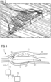
- FIG. 4 The diagram shows the airfoil of a rotor blade 2 and an embodiment of the inventive load-mitigation arrangement 1.
- a detachable spoiler 10 is mounted near the leading edge LE and connected to a control apparatus 11, which can actuate the spoiler 10 in response to data 120 reported by a monitoring means 12.
- the controller 11 can be connected via any suitable interface to the spoiler 10, for example by a pressurized air hose 110 if the spoiler 10 is a pneumatic device; by an electrical lead 110 if the spoiler 10 is actuated by a stepper motor, etc.
- the monitoring means 12 may record wind speed, wind direction, etc. and report these values directly to the control apparatus 11. Alternatively, the monitoring means 12 may convert wind data into actuation levels from "mild” to "severe", and the control apparatus 11 can respond accordingly. By raising the moveable spoiler 10, the airflow over the suction side 2S of the airfoil is disturbed, breaking up its otherwise attached nature. The result is to greatly decrease or even eliminate the magnitude of the lift force.
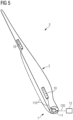
- FIG. 5 shows an exemplary embodiment of the inventive rotor blade assembly 3.
- a wind turbine rotor blade 2 is equipped with a temporary load-mitigation arrangement 1, comprising various spoilers 10 mounted on the rotor blade airfoil region, and a control arrangement 11 connected to the spoilers 10 so that these be actuated as required.
- the control arrangement 11 is configured to wirelessly receive input data 120 from a monitoring means 12, which can be local or at a remote location (e.g. a weather station on board an installation vessel), and to actuate the spoilers 10 on the basis of the input data 120.
- the control arrangement 11 can be provided to control spoilers 10 of a single rotor blade, or can be configured to control spoilers of multiple rotor blades that are stacked in similar orientations, for example a stack of rotor blades during open-air transport to an installation site.
- a spoiler can be maintained in its deployed position for the duration of a handling, storage or installation stage.
- the components of the load-mitigation arrangement 1 can be completely removed once the rotor blade 2 is mounted to the hub of a wind turbine.
- FIG. 6 shows another implementation of the inventive load-mitigation arrangement 1 in a rotor blade assembly 3.
- the diagram illustrates a stage during the installation procedure.
- a blade yoke 4 clamps a rotor blade 2 close to its centre of gravity.
- the blade yoke 4 is suspended by cable 40 from a crane (not shown), which is operated to raise the rotor blade 2 to the level of the wind turbine hub (not shown).
- the control arrangement 11 receives relevant data 120 from a weather station 12 mounted on the lifting yoke 4, and responds for example to any fluctuation in wind speed and/or wind direction by adjusting the spoilers 10 as appropriate. Because the controller 11 can adjust the spoilers 10 essentially immediately in response to changes in wind parameters to decrease the lift forces on the rotor blade 2, the lifting manoeuvre can be performed even during conditions that would otherwise be considered unfavourable or even dangerous.
- Figure 7 shows various possible spoiler arrangements for an embodiment of the inventive load mitigation arrangement.
- two spoilers 10 are used, with one spoiler 10 further inboard and one spoiler 10 further outboard.
- the inboard spoiler 10 extends partially into a region R1 with long chord length, i.e. into the inboard end of the rotor blade airfoil.
- the outboard spoiler 10 commences further along the airfoil region and extends towards the region R2 with short chord length.
- the inboard spoiler 10 can act to reduce lift load fluctuation, while the outboard spoiler 10 can act to increase the blade stability thereby reducing induced oscillation of the thin and flexible blade tip.
- the next embodiment shows a single spoiler 10 that extends over much of the region R1 with long chord length.
- This spoiler 10 can act primarily to reduce lift load fluctuation, and can also assist in reducing oscillation of the outboard blade region.
- the embodiment on the right also shows a single spoiler 10, which in this case extends over much of the region R1 with long chord length and also over the root region. This arrangement can serve to reduce lift load fluctuation.
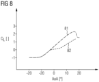
- Figure 8 illustrates the effect of the inventive load mitigation arrangement.
- the diagram shows curves 81, 82 of lift-coefficient (Y-axis, dimensionless number) against angle of attack AoA (in degrees).
- the angle of attack will depend on the position along the rotor blade as well as the airflow direction.
- the curve 81 corresponds to a rotor blade without any embodiment of the inventive load mitigation arrangement.
- the lift coefficient increases steadily as the angle of attack increases from -10° towards 20°. While this is generally an advantageous property for a rotor blade during normal operation of a wind turbine, it can lead to problems during storage, transport and installation, since the high lift forces acting on the non-mounted rotor blade require robust and expensive handling equipment.
- the curve 82 corresponds to an equivalent rotor blade that is equipped with an embodiment of the inventive load mitigation arrangement.
- the lift coefficient increases less steeply as the angle of attack increases from 0° towards 20°.
- the lower lift coefficient can reduce the loads on rotor blade handling equipment during storage, transport and installation, and can therefore significantly reduce costs as well as extending the "window of opportunity" for rotor blade installation.
- a spoiler can be an integral part of the blade, and after installation the spoiler can be connected to a control system of the wind turbine so that it can be used for load control during operation.
Landscapes
- Engineering & Computer Science (AREA)
- Life Sciences & Earth Sciences (AREA)
- Sustainable Development (AREA)
- Sustainable Energy (AREA)
- Chemical & Material Sciences (AREA)
- Combustion & Propulsion (AREA)
- Mechanical Engineering (AREA)
- General Engineering & Computer Science (AREA)
- Physics & Mathematics (AREA)
- Fluid Mechanics (AREA)
- Wind Motors (AREA)
Claims (12)
- Agencement d'atténuation de charge (1) d'une pale de rotor (2) non montée, comprenant- au moins un dispositif de modification de levage (10) pouvant être actionné agencé sur une surface (2S, 2P) de la pale de rotor (2) ;- un moyen de surveillance (12) configuré pour estimer les magnitudes de charges agissant sur la pale de rotor (2) non montée ;- un dispositif de commande (11) configuré pour actionner le dispositif de modification de levage (10) sur la base des magnitudes estimées pour atténuer les charges agissant sur la pale de rotor (2) non montée,caractérisé en ce que :le dispositif de modification de levage (10) est monté de manière à pouvoir être détaché sur la pale de rotor (2), et/oule moyen de surveillance (12) comprend un agencement de capteur de mouvement, en particulier un accéléromètre, pour mesurer ou détecter une oscillation ou une vibration de la pale de rotor (2).
- Agencement d'atténuation de charge selon l'une quelconque des revendications précédentes, dans lequel le dispositif de modification de levage (10) est agencé dans la région du bord de fuite (LE) de la pale de rotor (2).
- Agencement d'atténuation de charge selon l'une quelconque des revendications précédentes, comprenant une alimentation électrique (13) configurée pour fournir de l'énergie à un actionneur du dispositif de modification de levage (10).
- Agencement d'atténuation de charge selon l'une quelconque des revendications précédentes, dans lequel un dispositif de modification de levage (10) est un dispositif pneumatique.
- Agencement d'atténuation de charge selon l'une quelconque des revendications précédentes, dans lequel le moyen de surveillance (12) est configuré pour mesurer une valeur de vitesse du vent, et dans lequel le moyen de surveillance (12) est préférablement également configuré pour déterminer le sens du vent.
- Agencement d'atténuation de charge selon l'une quelconque des revendications précédentes, dans lequel un moyen de surveillance (12) est agencé sur un étrier de levage (4) d'un ensemble de hissage afin de surveiller les conditions du vent durant une installation de la pale de rotor (2) et/ou un moyen de surveillance (12) est agencé sur un moyen de transport afin de surveiller les conditions du vent durant un transport de la pale de rotor (2) et/ou un moyen de surveillance (12) est agencé au niveau d'une installation de stockage afin de surveiller les conditions du vent durant un stockage de la pale de rotor (2).
- Agencement d'atténuation de charge selon l'une quelconque des revendications précédentes, comprenant un dispositif de modification de levage (10) dans une région (R1) de grande longueur de corde, et un dispositif de modification de levage (10) dans une région hors-bord (R2) de la pale de rotor (2).
- Ensemble pale de rotor (3) comprenant- une pale de rotor (2) prévue pour le montage au moyeu d'une éolienne ;- un agencement d'atténuation de charge (1) selon l'une quelconque des revendications 1 à 7, dans lequel au moins un dispositif de modification de levage (10) pouvant être actionné est agencé sur une surface (2S, 2P) de la pale de rotor (2) ; et- une interface d'actionnement (110) entre le dispositif de commande (11) et les dispositifs de modification de levage (10) de l'agencement d'atténuation de charge (1).
- Ensemble pale de rotor selon la revendication 8, comprenant un ou plusieurs dispositifs de modification de levage (10) agencés sur le côté aspiration (2S) de la pale de rotor (2).
- Ensemble pale de rotor selon la revendication 8 ou la revendication 9, comprenant de nombreux dispositifs de modification de levage (10) agencés dans une région de la pale de rotor (2) s'étendant entre 25 % et 75 % de la longueur de la pale de rotor.
- Procédé d'exécution d'une atténuation de charge sur une pale de rotor (2) non montée d'un ensemble pale de rotor (3) selon l'une quelconque des revendications 8 à 10, lequel procédé comprend les étapes consistant à- agencer au moins un dispositif de modification de levage (10) pouvant être actionné de l'agencement d'atténuation de charge (1) sur une surface (2S, 2P) de la pale de rotor (2) non montée ;- surveiller les charges agissant sur la pale de rotor (2) ;- actionner un dispositif de modification de levage (10) sur la base des charges surveillées, et- retirer un dispositif de modification de levage (10) pouvant être actionné après que la pale de rotor (2) a été montée au moyeu d'une éolienne.
- Procédé selon la revendication 11, comprenant une étape de détermination d'un seuil de charge du vent pour cette pale de rotor (2), et dans lequel l'atténuation de charge est exécutée de sorte qu'une charge du vent sur la pale de rotor (2) n'excède pas le seuil de charge du vent.
Applications Claiming Priority (2)
| Application Number | Priority Date | Filing Date | Title |
|---|---|---|---|
| EP20211453.4A EP4008901A1 (fr) | 2020-12-03 | 2020-12-03 | Agencement de réduction de charge |
| PCT/EP2021/081506 WO2022117314A1 (fr) | 2020-12-03 | 2021-11-12 | Agencement d'atténuation de charge |
Publications (2)
| Publication Number | Publication Date |
|---|---|
| EP4226040A1 EP4226040A1 (fr) | 2023-08-16 |
| EP4226040B1 true EP4226040B1 (fr) | 2025-06-18 |
Family
ID=73698580
Family Applications (2)
| Application Number | Title | Priority Date | Filing Date |
|---|---|---|---|
| EP20211453.4A Withdrawn EP4008901A1 (fr) | 2020-12-03 | 2020-12-03 | Agencement de réduction de charge |
| EP21810615.1A Active EP4226040B1 (fr) | 2020-12-03 | 2021-11-12 | Agencement de réduction de charge |
Family Applications Before (1)
| Application Number | Title | Priority Date | Filing Date |
|---|---|---|---|
| EP20211453.4A Withdrawn EP4008901A1 (fr) | 2020-12-03 | 2020-12-03 | Agencement de réduction de charge |
Country Status (5)
| Country | Link |
|---|---|
| US (1) | US12270379B2 (fr) |
| EP (2) | EP4008901A1 (fr) |
| CN (1) | CN116583668A (fr) |
| DK (1) | DK4226040T3 (fr) |
| WO (1) | WO2022117314A1 (fr) |
Families Citing this family (3)
| Publication number | Priority date | Publication date | Assignee | Title |
|---|---|---|---|---|
| EP4006336A1 (fr) * | 2020-11-25 | 2022-06-01 | Siemens Gamesa Renewable Energy A/S | Pale de rotor d'éolienne |
| EP4310320A1 (fr) | 2022-07-19 | 2024-01-24 | General Electric Renovables España S.L. | Dispositifs et procédés pour atténuer les vibrations dans des éoliennes |
| WO2024208874A1 (fr) * | 2023-04-03 | 2024-10-10 | Liftra Ip Aps | Procédé de levage d'une pale d'éolienne |
Citations (1)
| Publication number | Priority date | Publication date | Assignee | Title |
|---|---|---|---|---|
| EP3885572A1 (fr) * | 2020-03-25 | 2021-09-29 | Siemens Gamesa Renewable Energy A/S | Réduction de charge aérodynamique pendant l'installation et le fonctionnement de pales dans une éolienne |
Family Cites Families (14)
| Publication number | Priority date | Publication date | Assignee | Title |
|---|---|---|---|---|
| US7878459B2 (en) * | 2007-06-29 | 2011-02-01 | The Boeing Company | Aircraft systems with shape memory alloy (SMA) actuators, and associated methods |
| NL1035525C1 (nl) * | 2008-06-03 | 2009-07-06 | Hugo Karel Krop | Windmolen-propeller met uitschuifbare profieldelen. |
| US20110135466A1 (en) * | 2010-01-14 | 2011-06-09 | General Electric Company | System and method for monitoring and controlling wind turbine blade deflection |
| WO2011105887A1 (fr) * | 2010-02-26 | 2011-09-01 | Hoofdweg Managements Bv | Pales d'hélice d'éolienne à volets extensibles intégrés |
| US20110142676A1 (en) * | 2010-11-16 | 2011-06-16 | General Electric Company | Rotor blade assembly having an auxiliary blade |
| US8240993B2 (en) * | 2011-01-04 | 2012-08-14 | General Electric Company | System and method of manipulating a boundary layer across a rotor blade of a wind turbine |
| US8167554B2 (en) * | 2011-01-28 | 2012-05-01 | General Electric Corporation | Actuatable surface features for wind turbine rotor blades |
| US20120141271A1 (en) * | 2011-09-13 | 2012-06-07 | General Electric Company | Actuatable spoiler assemblies for wind turbine rotor blades |
| EP2669238B1 (fr) | 2012-06-01 | 2016-12-14 | Siemens Aktiengesellschaft | Manipulation facilitée de pales d'éolienne |
| EP2708734B1 (fr) * | 2012-09-13 | 2016-11-09 | ALSTOM Renewable Technologies | Pale d'éolienne et procédés de transport, de stockage et d'installation desdites pales |
| CN114382660A (zh) * | 2014-07-17 | 2022-04-22 | Lm Wp 专利控股有限公司 | 用于运输风力涡轮机叶片的模块系统 |
| DE102014215969A1 (de) * | 2014-08-12 | 2016-02-18 | Wobben Properties Gmbh | Verfahren zum Installieren eines Rotorblattes an einer Windenergieanlage |
| EP3225834B1 (fr) | 2016-03-31 | 2019-11-27 | Siemens Gamesa Renewable Energy A/S | Réduction de la charge d'une pale de rotor d'éolienne pendant une installation |
| GB2548899A (en) * | 2016-04-01 | 2017-10-04 | Wind Farm Analytics Ltd | Fluid measurement system for buildings and vehicles |
-
2020
- 2020-12-03 EP EP20211453.4A patent/EP4008901A1/fr not_active Withdrawn
-
2021
- 2021-11-12 CN CN202180081524.6A patent/CN116583668A/zh active Pending
- 2021-11-12 EP EP21810615.1A patent/EP4226040B1/fr active Active
- 2021-11-12 DK DK21810615.1T patent/DK4226040T3/da active
- 2021-11-12 WO PCT/EP2021/081506 patent/WO2022117314A1/fr not_active Ceased
- 2021-11-12 US US18/254,391 patent/US12270379B2/en active Active
Patent Citations (1)
| Publication number | Priority date | Publication date | Assignee | Title |
|---|---|---|---|---|
| EP3885572A1 (fr) * | 2020-03-25 | 2021-09-29 | Siemens Gamesa Renewable Energy A/S | Réduction de charge aérodynamique pendant l'installation et le fonctionnement de pales dans une éolienne |
Also Published As
| Publication number | Publication date |
|---|---|
| WO2022117314A1 (fr) | 2022-06-09 |
| EP4008901A1 (fr) | 2022-06-08 |
| DK4226040T3 (en) | 2025-08-18 |
| US20240035442A1 (en) | 2024-02-01 |
| EP4226040A1 (fr) | 2023-08-16 |
| CN116583668A (zh) | 2023-08-11 |
| US12270379B2 (en) | 2025-04-08 |
Similar Documents
| Publication | Publication Date | Title |
|---|---|---|
| US12270379B2 (en) | Load mitigation arrangement | |
| EP2128385B1 (fr) | Éolienne dotée de déflecteurs d'air déployables | |
| US8267654B2 (en) | Wind turbine with gust compensating air deflector | |
| CN100526639C (zh) | 操纵和安装风轮机叶片的方法和设备 | |
| US9689374B2 (en) | Method and apparatus for reduction of fatigue and gust loads on wind turbine blades | |
| EP3029317B1 (fr) | Procédé et appareil pour la réduction de la fatigue et de charges de rafales sur des pales d'éolienne | |
| EP2389510B1 (fr) | Commande d'un rotor d'eolienne au cours d'un processus d'arret par tangage et dispositif de modification de surface | |
| EP2708734B1 (fr) | Pale d'éolienne et procédés de transport, de stockage et d'installation desdites pales | |
| EP2141357A1 (fr) | Pale d'éolienne | |
| EP2778398A2 (fr) | Système de déploiement de sécurité pour déflecteur d'air du pale d'éolienne | |
| US12454938B2 (en) | Devices and methods for mitigating vibrations in wind turbines | |
| EP3673171B1 (fr) | Pale de turbine éolienne et procédé de fabrication d'une telle pale | |
| US11959456B2 (en) | Devices and methods for vibration mitigation on wind turbines | |
| EP4085193B1 (fr) | Procédé de stabilisation d'une pale d'éolienne | |
| EP3771818B1 (fr) | Ensemble de nacelle pour éolienne | |
| WO2020126207A1 (fr) | Pale de turbine éolienne, turbine éolienne, procédé de fabrication d'une pale de turbine éolienne et procédé de maintien d'une turbine éolienne | |
| WO2024208874A1 (fr) | Procédé de levage d'une pale d'éolienne |
Legal Events
| Date | Code | Title | Description |
|---|---|---|---|
| STAA | Information on the status of an ep patent application or granted ep patent |
Free format text: STATUS: UNKNOWN |
|
| STAA | Information on the status of an ep patent application or granted ep patent |
Free format text: STATUS: THE INTERNATIONAL PUBLICATION HAS BEEN MADE |
|
| PUAI | Public reference made under article 153(3) epc to a published international application that has entered the european phase |
Free format text: ORIGINAL CODE: 0009012 |
|
| STAA | Information on the status of an ep patent application or granted ep patent |
Free format text: STATUS: REQUEST FOR EXAMINATION WAS MADE |
|
| 17P | Request for examination filed |
Effective date: 20230509 |
|
| AK | Designated contracting states |
Kind code of ref document: A1 Designated state(s): AL AT BE BG CH CY CZ DE DK EE ES FI FR GB GR HR HU IE IS IT LI LT LU LV MC MK MT NL NO PL PT RO RS SE SI SK SM TR |
|
| DAV | Request for validation of the european patent (deleted) | ||
| DAX | Request for extension of the european patent (deleted) | ||
| STAA | Information on the status of an ep patent application or granted ep patent |
Free format text: STATUS: EXAMINATION IS IN PROGRESS |
|
| 17Q | First examination report despatched |
Effective date: 20240321 |
|
| GRAP | Despatch of communication of intention to grant a patent |
Free format text: ORIGINAL CODE: EPIDOSNIGR1 |
|
| STAA | Information on the status of an ep patent application or granted ep patent |
Free format text: STATUS: GRANT OF PATENT IS INTENDED |
|
| INTG | Intention to grant announced |
Effective date: 20250130 |
|
| GRAS | Grant fee paid |
Free format text: ORIGINAL CODE: EPIDOSNIGR3 |
|
| GRAA | (expected) grant |
Free format text: ORIGINAL CODE: 0009210 |
|
| STAA | Information on the status of an ep patent application or granted ep patent |
Free format text: STATUS: THE PATENT HAS BEEN GRANTED |
|
| AK | Designated contracting states |
Kind code of ref document: B1 Designated state(s): AL AT BE BG CH CY CZ DE DK EE ES FI FR GB GR HR HU IE IS IT LI LT LU LV MC MK MT NL NO PL PT RO RS SE SI SK SM TR |
|
| REG | Reference to a national code |
Ref country code: GB Ref legal event code: FG4D |
|
| REG | Reference to a national code |
Ref country code: CH Ref legal event code: EP |
|
| REG | Reference to a national code |
Ref country code: DE Ref legal event code: R096 Ref document number: 602021032540 Country of ref document: DE |
|
| REG | Reference to a national code |
Ref country code: CH Ref legal event code: EP |
|
| REG | Reference to a national code |
Ref country code: IE Ref legal event code: FG4D |
|
| REG | Reference to a national code |
Ref country code: DK Ref legal event code: T3 Effective date: 20250807 |
|
| PG25 | Lapsed in a contracting state [announced via postgrant information from national office to epo] |
Ref country code: FI Free format text: LAPSE BECAUSE OF FAILURE TO SUBMIT A TRANSLATION OF THE DESCRIPTION OR TO PAY THE FEE WITHIN THE PRESCRIBED TIME-LIMIT Effective date: 20250618 |
|
| PGFP | Annual fee paid to national office [announced via postgrant information from national office to epo] |
Ref country code: DK Payment date: 20250901 Year of fee payment: 5 |
|
| REG | Reference to a national code |
Ref country code: LT Ref legal event code: MG9D |
|
| PG25 | Lapsed in a contracting state [announced via postgrant information from national office to epo] |
Ref country code: GR Free format text: LAPSE BECAUSE OF FAILURE TO SUBMIT A TRANSLATION OF THE DESCRIPTION OR TO PAY THE FEE WITHIN THE PRESCRIBED TIME-LIMIT Effective date: 20250919 Ref country code: NO Free format text: LAPSE BECAUSE OF FAILURE TO SUBMIT A TRANSLATION OF THE DESCRIPTION OR TO PAY THE FEE WITHIN THE PRESCRIBED TIME-LIMIT Effective date: 20250918 |
|
| PG25 | Lapsed in a contracting state [announced via postgrant information from national office to epo] |
Ref country code: BG Free format text: LAPSE BECAUSE OF FAILURE TO SUBMIT A TRANSLATION OF THE DESCRIPTION OR TO PAY THE FEE WITHIN THE PRESCRIBED TIME-LIMIT Effective date: 20250618 |
|
| PGFP | Annual fee paid to national office [announced via postgrant information from national office to epo] |
Ref country code: GB Payment date: 20250901 Year of fee payment: 5 |
|
| PG25 | Lapsed in a contracting state [announced via postgrant information from national office to epo] |
Ref country code: HR Free format text: LAPSE BECAUSE OF FAILURE TO SUBMIT A TRANSLATION OF THE DESCRIPTION OR TO PAY THE FEE WITHIN THE PRESCRIBED TIME-LIMIT Effective date: 20250618 |
|
| PG25 | Lapsed in a contracting state [announced via postgrant information from national office to epo] |
Ref country code: RS Free format text: LAPSE BECAUSE OF FAILURE TO SUBMIT A TRANSLATION OF THE DESCRIPTION OR TO PAY THE FEE WITHIN THE PRESCRIBED TIME-LIMIT Effective date: 20250918 |
|
| REG | Reference to a national code |
Ref country code: NL Ref legal event code: MP Effective date: 20250618 |
|
| PG25 | Lapsed in a contracting state [announced via postgrant information from national office to epo] |
Ref country code: LV Free format text: LAPSE BECAUSE OF FAILURE TO SUBMIT A TRANSLATION OF THE DESCRIPTION OR TO PAY THE FEE WITHIN THE PRESCRIBED TIME-LIMIT Effective date: 20250618 |
|
| PG25 | Lapsed in a contracting state [announced via postgrant information from national office to epo] |
Ref country code: NL Free format text: LAPSE BECAUSE OF FAILURE TO SUBMIT A TRANSLATION OF THE DESCRIPTION OR TO PAY THE FEE WITHIN THE PRESCRIBED TIME-LIMIT Effective date: 20250618 |
|
| PG25 | Lapsed in a contracting state [announced via postgrant information from national office to epo] |
Ref country code: PT Free format text: LAPSE BECAUSE OF FAILURE TO SUBMIT A TRANSLATION OF THE DESCRIPTION OR TO PAY THE FEE WITHIN THE PRESCRIBED TIME-LIMIT Effective date: 20251020 |
|
| REG | Reference to a national code |
Ref country code: AT Ref legal event code: MK05 Ref document number: 1804379 Country of ref document: AT Kind code of ref document: T Effective date: 20250618 |
|
| PG25 | Lapsed in a contracting state [announced via postgrant information from national office to epo] |
Ref country code: IS Free format text: LAPSE BECAUSE OF FAILURE TO SUBMIT A TRANSLATION OF THE DESCRIPTION OR TO PAY THE FEE WITHIN THE PRESCRIBED TIME-LIMIT Effective date: 20251018 |
|
| PGFP | Annual fee paid to national office [announced via postgrant information from national office to epo] |
Ref country code: DE Payment date: 20250829 Year of fee payment: 5 |
|
| PG25 | Lapsed in a contracting state [announced via postgrant information from national office to epo] |
Ref country code: AT Free format text: LAPSE BECAUSE OF FAILURE TO SUBMIT A TRANSLATION OF THE DESCRIPTION OR TO PAY THE FEE WITHIN THE PRESCRIBED TIME-LIMIT Effective date: 20250618 Ref country code: SM Free format text: LAPSE BECAUSE OF FAILURE TO SUBMIT A TRANSLATION OF THE DESCRIPTION OR TO PAY THE FEE WITHIN THE PRESCRIBED TIME-LIMIT Effective date: 20250618 |
|
| PGFP | Annual fee paid to national office [announced via postgrant information from national office to epo] |
Ref country code: FR Payment date: 20251124 Year of fee payment: 5 |
|
| PG25 | Lapsed in a contracting state [announced via postgrant information from national office to epo] |
Ref country code: CZ Free format text: LAPSE BECAUSE OF FAILURE TO SUBMIT A TRANSLATION OF THE DESCRIPTION OR TO PAY THE FEE WITHIN THE PRESCRIBED TIME-LIMIT Effective date: 20250618 |
|
| PG25 | Lapsed in a contracting state [announced via postgrant information from national office to epo] |
Ref country code: PL Free format text: LAPSE BECAUSE OF FAILURE TO SUBMIT A TRANSLATION OF THE DESCRIPTION OR TO PAY THE FEE WITHIN THE PRESCRIBED TIME-LIMIT Effective date: 20250618 |
|
| PG25 | Lapsed in a contracting state [announced via postgrant information from national office to epo] |
Ref country code: EE Free format text: LAPSE BECAUSE OF FAILURE TO SUBMIT A TRANSLATION OF THE DESCRIPTION OR TO PAY THE FEE WITHIN THE PRESCRIBED TIME-LIMIT Effective date: 20250618 |
|
| PG25 | Lapsed in a contracting state [announced via postgrant information from national office to epo] |
Ref country code: SK Free format text: LAPSE BECAUSE OF FAILURE TO SUBMIT A TRANSLATION OF THE DESCRIPTION OR TO PAY THE FEE WITHIN THE PRESCRIBED TIME-LIMIT Effective date: 20250618 |
|
| PG25 | Lapsed in a contracting state [announced via postgrant information from national office to epo] |
Ref country code: ES Free format text: LAPSE BECAUSE OF FAILURE TO SUBMIT A TRANSLATION OF THE DESCRIPTION OR TO PAY THE FEE WITHIN THE PRESCRIBED TIME-LIMIT Effective date: 20250618 |
|
| PG25 | Lapsed in a contracting state [announced via postgrant information from national office to epo] |
Ref country code: RO Free format text: LAPSE BECAUSE OF FAILURE TO SUBMIT A TRANSLATION OF THE DESCRIPTION OR TO PAY THE FEE WITHIN THE PRESCRIBED TIME-LIMIT Effective date: 20250618 |
|
| REG | Reference to a national code |
Ref country code: DE Ref legal event code: R097 Ref document number: 602021032540 Country of ref document: DE |
|
| PG25 | Lapsed in a contracting state [announced via postgrant information from national office to epo] |
Ref country code: IT Free format text: LAPSE BECAUSE OF FAILURE TO SUBMIT A TRANSLATION OF THE DESCRIPTION OR TO PAY THE FEE WITHIN THE PRESCRIBED TIME-LIMIT Effective date: 20250618 |
|
| PLBE | No opposition filed within time limit |
Free format text: ORIGINAL CODE: 0009261 |
|
| STAA | Information on the status of an ep patent application or granted ep patent |
Free format text: STATUS: NO OPPOSITION FILED WITHIN TIME LIMIT |
|
| REG | Reference to a national code |
Ref country code: CH Ref legal event code: L10 Free format text: ST27 STATUS EVENT CODE: U-0-0-L10-L00 (AS PROVIDED BY THE NATIONAL OFFICE) Effective date: 20260430 |