EP4226231B1 - Konditioniersystem für einen prüfstand - Google Patents
Konditioniersystem für einen prüfstand Download PDFInfo
- Publication number
- EP4226231B1 EP4226231B1 EP21791244.3A EP21791244A EP4226231B1 EP 4226231 B1 EP4226231 B1 EP 4226231B1 EP 21791244 A EP21791244 A EP 21791244A EP 4226231 B1 EP4226231 B1 EP 4226231B1
- Authority
- EP
- European Patent Office
- Prior art keywords
- unit
- conditioning
- operating medium
- mixing
- temperature
- Prior art date
- Legal status (The legal status is an assumption and is not a legal conclusion. Google has not performed a legal analysis and makes no representation as to the accuracy of the status listed.)
- Active
Links
Images


Classifications
-
- B—PERFORMING OPERATIONS; TRANSPORTING
- B01—PHYSICAL OR CHEMICAL PROCESSES OR APPARATUS IN GENERAL
- B01F—MIXING, e.g. DISSOLVING, EMULSIFYING OR DISPERSING
- B01F23/00—Mixing according to the phases to be mixed, e.g. dispersing or emulsifying
- B01F23/40—Mixing liquids with liquids; Emulsifying
- B01F23/45—Mixing liquids with liquids; Emulsifying using flow mixing
- B01F23/453—Mixing liquids with liquids; Emulsifying using flow mixing by moving the liquids in countercurrent
-
- B—PERFORMING OPERATIONS; TRANSPORTING
- B01—PHYSICAL OR CHEMICAL PROCESSES OR APPARATUS IN GENERAL
- B01F—MIXING, e.g. DISSOLVING, EMULSIFYING OR DISPERSING
- B01F25/00—Flow mixers; Mixers for falling materials, e.g. solid particles
- B01F25/20—Jet mixers, i.e. mixers using high-speed fluid streams
- B01F25/23—Mixing by intersecting jets
-
- B—PERFORMING OPERATIONS; TRANSPORTING
- B01—PHYSICAL OR CHEMICAL PROCESSES OR APPARATUS IN GENERAL
- B01F—MIXING, e.g. DISSOLVING, EMULSIFYING OR DISPERSING
- B01F25/00—Flow mixers; Mixers for falling materials, e.g. solid particles
- B01F25/40—Static mixers
- B01F25/42—Static mixers in which the mixing is affected by moving the components jointly in changing directions, e.g. in tubes provided with baffles or obstructions
- B01F25/43—Mixing tubes, e.g. wherein the material is moved in a radial or partly reversed direction
- B01F25/432—Mixing tubes, e.g. wherein the material is moved in a radial or partly reversed direction with means for dividing the material flow into separate sub-flows and for repositioning and recombining these sub-flows; Cross-mixing, e.g. conducting the outer layer of the material nearer to the axis of the tube or vice-versa
-
- B—PERFORMING OPERATIONS; TRANSPORTING
- B01—PHYSICAL OR CHEMICAL PROCESSES OR APPARATUS IN GENERAL
- B01F—MIXING, e.g. DISSOLVING, EMULSIFYING OR DISPERSING
- B01F25/00—Flow mixers; Mixers for falling materials, e.g. solid particles
- B01F25/40—Static mixers
- B01F25/45—Mixers in which the materials to be mixed are pressed together through orifices or interstitial spaces, e.g. between beads
- B01F25/452—Mixers in which the materials to be mixed are pressed together through orifices or interstitial spaces, e.g. between beads characterised by elements provided with orifices or interstitial spaces
- B01F25/4523—Mixers in which the materials to be mixed are pressed together through orifices or interstitial spaces, e.g. between beads characterised by elements provided with orifices or interstitial spaces the components being pressed through sieves, screens or meshes which obstruct the whole diameter of the tube
-
- B—PERFORMING OPERATIONS; TRANSPORTING
- B01—PHYSICAL OR CHEMICAL PROCESSES OR APPARATUS IN GENERAL
- B01F—MIXING, e.g. DISSOLVING, EMULSIFYING OR DISPERSING
- B01F33/00—Other mixers; Mixing plants; Combinations of mixers
- B01F33/80—Mixing plants; Combinations of mixers
- B01F33/81—Combinations of similar mixers, e.g. with rotary stirring devices in two or more receptacles
- B01F33/811—Combinations of similar mixers, e.g. with rotary stirring devices in two or more receptacles in two or more consecutive, i.e. successive, mixing receptacles or being consecutively arranged
-
- B—PERFORMING OPERATIONS; TRANSPORTING
- B01—PHYSICAL OR CHEMICAL PROCESSES OR APPARATUS IN GENERAL
- B01F—MIXING, e.g. DISSOLVING, EMULSIFYING OR DISPERSING
- B01F33/00—Other mixers; Mixing plants; Combinations of mixers
- B01F33/80—Mixing plants; Combinations of mixers
- B01F33/82—Combinations of dissimilar mixers
- B01F33/821—Combinations of dissimilar mixers with consecutive receptacles
-
- B—PERFORMING OPERATIONS; TRANSPORTING
- B01—PHYSICAL OR CHEMICAL PROCESSES OR APPARATUS IN GENERAL
- B01F—MIXING, e.g. DISSOLVING, EMULSIFYING OR DISPERSING
- B01F35/00—Accessories for mixers; Auxiliary operations or auxiliary devices; Parts or details of general application
- B01F35/20—Measuring; Control or regulation
- B01F35/22—Control or regulation
- B01F35/221—Control or regulation of operational parameters, e.g. level of material in the mixer, temperature or pressure
- B01F35/2215—Temperature
-
- G—PHYSICS
- G01—MEASURING; TESTING
- G01M—TESTING STATIC OR DYNAMIC BALANCE OF MACHINES OR STRUCTURES; TESTING OF STRUCTURES OR APPARATUS, NOT OTHERWISE PROVIDED FOR
- G01M15/00—Testing of engines
- G01M15/02—Details or accessories of testing apparatus
-
- G—PHYSICS
- G01—MEASURING; TESTING
- G01M—TESTING STATIC OR DYNAMIC BALANCE OF MACHINES OR STRUCTURES; TESTING OF STRUCTURES OR APPARATUS, NOT OTHERWISE PROVIDED FOR
- G01M17/00—Testing of vehicles
-
- G—PHYSICS
- G01—MEASURING; TESTING
- G01M—TESTING STATIC OR DYNAMIC BALANCE OF MACHINES OR STRUCTURES; TESTING OF STRUCTURES OR APPARATUS, NOT OTHERWISE PROVIDED FOR
- G01M99/00—Subject matter not provided for in other groups of this subclass
- G01M99/002—Thermal testing
-
- G—PHYSICS
- G05—CONTROLLING; REGULATING
- G05D—SYSTEMS FOR CONTROLLING OR REGULATING NON-ELECTRIC VARIABLES
- G05D23/00—Control of temperature
- G05D23/01—Control of temperature without auxiliary power
- G05D23/13—Control of temperature without auxiliary power by varying the mixing ratio of two fluids having different temperatures
-
- G—PHYSICS
- G05—CONTROLLING; REGULATING
- G05D—SYSTEMS FOR CONTROLLING OR REGULATING NON-ELECTRIC VARIABLES
- G05D23/00—Control of temperature
- G05D23/01—Control of temperature without auxiliary power
- G05D23/13—Control of temperature without auxiliary power by varying the mixing ratio of two fluids having different temperatures
- G05D23/1393—Control of temperature without auxiliary power by varying the mixing ratio of two fluids having different temperatures characterised by the use of electric means
Definitions
- the invention relates to a mixing unit for a conditioning system of a test bench for conditioning an operating medium of a test object circuit of a test object set up on the test bench to a predetermined target temperature, and to a conditioning unit for a conditioning system of a test bench for conditioning an operating medium of a test object circuit of a test object set up on the test bench to a predetermined target temperature.
- the invention also relates to a conditioning system for a test bench for conditioning an operating medium of a test object circuit of a test object set up on the test bench to a predetermined target temperature, and to a test bench with a test object and with a conditioning system for conditioning an operating medium of a test object circuit of the test object to a predetermined target temperature.
- the invention also relates to a method for conditioning an operating medium of a test object circuit of a test object on a test bench to a predetermined target temperature.
- Conditioning systems can be used on test benches for certain test tests in order to condition certain liquid or gaseous operating media of a test object to a desired temperature.
- a subsystem of a vehicle is, for example, a drive train, which can comprise one or more components, such as drive units, transmissions, etc.
- a component can be, for example, a drive unit such as an internal combustion engine, electric motors, combinations of internal combustion engines and electric motors (so-called hybrid drives).
- Components can also be, for example, fuel cells, batteries, transmissions, etc.
- Each test object usually has at least one test object circuit for an operating medium, such as a coolant, fuel, lubricating oil, etc.
- the operating medium circulates in the test object circuit, usually involving heat input into the operating medium. It is often desired to set certain temporal temperature profiles of the operating medium in the test object circuit on the test bench as precisely and as quickly as possible. For example, it may be desirable to recreate a temperature profile of an operating medium of the test object on the test bench that was previously recorded under real conditions (for example in a real vehicle while driving on a certain route) or a temperature profile that was simulated at the same time. It may also be desirable to keep the temperature at as constant a level as possible. In particular, rapid temperature changes of the operating medium on the test bench by means of a conditioning system can only be inadequately regulated to date, which is essentially due to the relatively high thermal inertia of the operating media used.
- Conditioning systems and components of conditioning systems are made of WO 2019/183658 A1 , WO 2019/149792 A1 , EP 3 293 504 A1 , DE 10 2009 013449 A1 or from US 2019/091641 A1 known.
- the object is achieved with a conditioning unit in that at least one mixing unit inlet connection and at least one mixing unit outlet connection are provided on the conditioning unit for connecting the conditioning unit to a mixing unit that can be fluidically integrated into the test object circuit, wherein the at least one mixing unit inlet connection and the at least one mixing unit outlet connection are fluidically connected within the conditioning unit in order to form part of a conditioning circuit for the operating medium, wherein a main flow line of the conditioning circuit connected to the at least one mixing unit inlet connection is divided into at least two partial flow lines in the conditioning unit, wherein each partial flow line is connected to the at least one mixing unit outlet connection, wherein the operating medium can be conditioned to a predetermined conditioning temperature in a partial flow line and the at least one further partial flow line can be flowed through by unconditioned operating medium with a neutral temperature that is higher or lower relative to the conditioning temperature, wherein a The flow of the operating medium in the at least two partial flow lines can be adjusted depending on the specified target temperature in the test object circuit. By adjusting the flow,
- a mixing unit is fluidically integrated into the test specimen circuit in order to form a part of the test specimen circuit, wherein operating medium of the test specimen circuit to be conditioned is supplied to the mixing unit via at least one test specimen circuit inlet connection and operating medium conditioned to the predetermined target temperature is discharged from the mixing unit via at least one test specimen circuit outlet connection, wherein at least operating medium with a predetermined conditioning temperature and operating medium with a relatively higher or lower neutral temperature, which is mixed with the supplied operating medium of the test object circuit in a mixing area provided within the mixing unit and is discharged from the mixing unit via at least one conditioning unit return connection, wherein a flow of the operating medium with the conditioning temperature and a flow of the operating medium with the neutral temperature are set depending on the predetermined target temperature.
- the object can also be achieved advantageously with a mixing unit in that a mixing area is provided in the mixing unit in which the operating medium of the test object circuit can be mixed with preconditioned operating medium from a conditioning circuit in order to condition the operating medium in the test object circuit to the predetermined target temperature, wherein at least one test object circuit inlet connection and at least one test object circuit outlet connection are provided on the mixing unit for the fluidic integration of the mixing unit into the test object circuit, which are fluidically connected to one another via the mixing area in order to form part of the test object circuit, wherein at least one conditioning unit inlet connection and at least one conditioning unit return connection are provided on the mixing unit for connecting the mixing unit to a conditioning unit of the conditioning system, which are fluidically connected to one another via the mixing area in order to form part of the conditioning circuit for the operating medium.
- Fig.1a shows a schematic representation of a conditioning system 1 according to the invention on a test bench in an advantageous embodiment.
- the conditioning system 1 has a conditioning unit 2 and a mixing unit 3, which are fluidically connected to one another in order to form a conditioning circuit KK for a fluid operating medium.
- a fluid operating medium is to be understood here as a suitable gaseous or liquid medium.
- a coolant, a fuel, an oil, air, etc. can be provided as the operating medium.
- "fluidically connected” is to be understood as a fluid-mechanical connection, for example via suitable pipes, lines, etc.
- the mixing unit 3 can be fluidically integrated into a test specimen circuit PK of a test specimen P installed on a test bench, in which the same operating medium circulates.
- the type of operating medium used in the conditioning circuit KK depends on the operating medium used in the test specimen circuit PK of the test specimen P.
- the test object P can be, for example, a transmission such as a manual transmission, automatic transmission or axle transmission, a drive unit such as an internal combustion engine, electric motor, hybrid drive, an energy storage device such as a battery or an energy converter such as a fuel cell, etc.
- a transmission such as a manual transmission, automatic transmission or axle transmission
- a drive unit such as an internal combustion engine, electric motor, hybrid drive
- an energy storage device such as a battery or an energy converter such as a fuel cell, etc.
- any test object P can be used with a test object circuit PK with operating medium.
- test bench control unit 21 is usually provided in a known manner.
- a pump for conveying the operating medium can of course also be provided, which can be part of the test bench or part of the test specimen P.
- other components such as heat exchangers, valves, sensors, throttles, etc. can also be provided in the test specimen circuit PK, but these are irrelevant for the invention.
- the mixing unit 3 can, as in Fig.1 shown, in the flow direction of the operating medium after the test specimen P in the test specimen circuit PK.
- the mixing unit 3 can also be integrated in the flow direction of the operating medium before the test specimen P, as in Fig.1 indicated by the dashed test specimen P.
- the temperature behavior of the operating medium is to be simulated on the test bench with the help of the conditioning system 1.
- the conditioning system 1 is to simulate the heat input of the test object P into the test object circuit PK, which results from the operation of the test object P.
- the test object P can actually be operated as intended on the test bench so that it itself performs work that heats the operating medium in the test object circuit PK.
- the conditioning system 1 could be used, for example, to simulate a higher or lower heat input of the test object P.
- the test object P can also be used simply to be able to depict the pressure loss in the test object circuit PK caused by the test object P as realistically as possible. In this case, the test object P is not operated itself, i.e. it does not cause any heat input into the operating medium of the test object circuit PK, but its heat input is emulated by the conditioning system 1 according to the invention.
- preconditioned operating medium from the conditioning circuit KK and the operating medium of the test item circuit PK are mixed in the mixing unit 3 in such a way that a predetermined target temperature T_TARGET of the operating medium in the test item circuit PK is set downstream of the mixing unit 3.
- the preconditioning of the operating medium in the conditioning circuit KK is carried out by the conditioning unit 2, as explained in more detail below.
- Advantageous embodiments of the mixing unit 3 are described using Fig.2 + Fig.3 as well as Fig.4 described in more detail.
- At least one mixing unit inlet connection 4 and at least one mixing unit outlet connection 5 are provided on the conditioning unit 2 for connecting the conditioning unit 2 to the mixing unit 3.
- three mixing unit outlet connections 5a-5c are provided.
- the mixing unit inlet connection 4 is fluidically connected to the three mixing unit outlet connections 5a-5c within the conditioning unit 2 in order to form part of the conditioning circuit KK for the operating medium.
- a main flow line 6 of the conditioning circuit KK connected to the mixing unit inlet connection 4 is divided within the conditioning unit 2 into at least two partial flow lines 7a+7c (or 7b+7c), for example at a distribution node 8.
- the operating medium in one of the at least two partial flow lines 7a, 7b can be conditioned to a predetermined conditioning temperature T1, T2 and the at least one further partial flow line 7c is filled with unconditioned operating medium with a neutral temperature T3 that is higher or lower relative to the conditioning temperature T1, T2.
- the embodiment with a conditioning temperature T1 that is higher than the neutral temperature T3 can be used if only heating of the operating medium in the test object circuit PK is desired.
- the embodiment with a conditioning temperature T2 that is lower than the neutral temperature T3 can be used if cooling of the operating medium in the test object circuit PK is desired.
- a suitable temperature control unit 9a, 9b can be provided in the respective partial flow line 7a, 7b, as will be explained in more detail below.
- the main flow line 6 is divided within the conditioning unit 2 into three partial flow lines 7a, 7b, 7c, so that the operating medium can be heated in the first partial flow line 7a and cooled in the second partial flow line 7b.
- a preferably controllable or adjustable pump 15 for conveying the operating medium in the conditioning circuit KK can be provided in the main flow line 6, but a pump (not shown) can also be provided in each of the partial flow lines 7a-7c.
- a bypass line 16 for the operating medium can also be provided, which connects the main flow line 6 upstream of the pump 15 with the main flow line 6 downstream of the pump in order to bypass the pump 15.
- a controllable valve 17 can be provided in the bypass line 16 in order to reduce, preferably completely compensate, a pressure loss ⁇ p in the test specimen circuit PK caused by the mixing unit 3, as will be explained below with reference to the Fig.2-Fig.4
- a throttle point 29 with an adjustable orifice can also be provided in the mixing unit 3, via which the pressure loss can be compensated, as can also be seen from Fig.2-Fig.4 will be explained in more detail.
- Each partial flow line 7a-7c within the conditioning unit 2 is connected to a mixing unit outlet connection 5a-5c.
- the mixing unit outlet connections 5a-5c can in turn be connected to the mixing unit 3, for example via supply lines ZLa-Zlc, in order to supply the preconditioned operating medium to the mixing unit 3.
- the operating medium can be conditioned to a first conditioning temperature T1 in a first partial flow line 7a and to a second conditioning temperature T2 in a second partial flow line 7b.
- the operating medium can flow through a third partial flow line 7c with a neutral temperature T3 lying between the first and second temperatures and is preferably not conditioned separately.
- the temperature ranges of the conditioning temperatures T1, T2 depend essentially on on the specified boundary conditions or requirements for the conditioning system 1, such as a minimum or maximum required target temperature T_TARGET of the operating medium and/or the operating medium used.
- the neutral temperature T3 lying between the conditioning temperatures T1, T2 depends essentially on the temperature of the operating medium flowing back from the mixing unit 3.
- At least one first temperature control unit 9a is provided in the first partial flow line 7a in the conditioning unit 2 in order to condition the operating medium to the first (high) conditioning temperature T1.
- at least one second temperature control unit 9b is preferably provided in the second partial flow line 7b in order to condition the operating medium to the second (low) conditioning temperature T2.
- all devices that are suitable for conditioning the operating medium in the first and second partial flow lines 7a, 7b to the respectively intended conditioning temperatures T1, T2 can be used as temperature control units 9a, 9b, such as heat exchangers, (e.g. electric) heating devices, cooling devices, heat pumps, Peltier elements, etc.
- At least one heat source flow connection 10a and at least one heat source return connection 10b for connecting a heat source can be provided on the conditioning unit 2.
- the heat source flow connection 10a and the heat source return connection 10b can be fluidically connected to the first temperature control unit 9a designed as a heat exchanger in order to form part of a heat source supply circuit VK1.
- At least one heat sink flow connection 11a and at least one heat sink return connection 11b for connecting the heat sink can also be provided on the conditioning unit 2, which are fluidically connected to the second temperature control unit 9b designed as a heat exchanger in order to form part of a heat sink supply circuit VK2.
- any suitable device can be used as the heat source, with which the supply medium of the heat source supply circuit VK1 is kept at a relatively high supply temperature that is as constant as possible, for example in the range of 10K above the maximum required target temperature.
- any suitable device can be used as the heat sink, with which the supply medium of the heat sink supply circuit VK2 is kept at a relatively low supply temperature that is as constant as possible, for example in the range of 10K below the minimum required target temperature.
- the supply medium can be, for example, the operating medium or another suitable medium.
- the heat supply by the heat source and heat sink can, for example, take place in a separate supply module 12, which forms a self-sufficient unit to which the conditioning unit 2 can be connected.
- a separate supply module 12 which forms a self-sufficient unit to which the conditioning unit 2 can be connected.
- other hydraulic components (not shown) for the supply circuits VK1, VK2 can of course also be provided, for example pumps, pressure control devices, valves, tanks, etc.
- the control of the supply module 12 could, for example, be carried out by a conditioning unit control unit 20, which can, for example, be arranged in the conditioning unit 2.
- the control of the supply module 12 could, however, also be carried out by a test bench control unit 21 of the test bench on which the conditioning system 1 is used (as shown by the dashed connecting line in Fig.1 is indicated).
- a central media supply system is often provided on test benches for the provision of preconditioned supply media, for example as part of the test bench building.
- several, even different types of test benches can be supplied with one or more preconditioned supply media via the central media supply system.
- the provision of the preconditioned supply media for the supply circuits VK1, VK2 of the first and second temperature control units 9a, 9b, in particular heat exchangers could in this case be carried out via supply lines L1, L2 of the central media supply system, for example, as in Fig.1a is indicated. In this case, a separate supply module 12 is not necessary.
- the conditioning unit 2 is designed to control, in particular to regulate, a flow of the operating medium, e.g. volume flow or mass flow, in the three partial flow lines 7a-7c (or generally at least two partial flow lines 7a+7c or 7b+7c) depending on the specified target temperature T_SOLL of the operating medium in the test item circuit PK, so that the target temperature T_SOLL in the test item circuit PK can be set as quickly as possible.
- a flow of the operating medium e.g. volume flow or mass flow
- the preconditioned operating medium from the partial flow lines 7a-7c of the conditioning unit 2 is mixed with the operating medium in the test item circuit PK depending on the specified target temperature T_SOLL test item circuit PK, wherein the mixing takes place in the mixing unit 3, in particular in a mixing area 28 of the mixing unit 3, as described below with reference to Fig.2-Fig.4 will be explained in more detail below.
- the conditioning unit 2 can be connected to the mixing unit 3, for example, via one or more suitable supply lines ZLa-ZLc and one or more suitable return lines RL.
- At least one conditioning unit inlet connection 27a and one conditioning unit return connection 27b are provided on the mixing unit 3.
- the conditioning unit return connection 27b can be connected to the mixing unit inlet connection 4 of the conditioning unit 2 via the return line RL.
- a supply line ZLa-ZLc is connected to each mixing unit outlet connection 5a-5c of the conditioning unit 2. If a single conditioning unit supply connection 27a is provided on the mixing unit 3, the supply lines ZLa-ZLc can preferably be combined to form a common collecting line SL immediately before the mixing unit 3, as shown in Fig.1a is indicated. The common collecting line SL can then be connected to the conditioning unit inlet connection 27a.
- conditioning unit inlet connections 27a could also be provided on the mixing unit 3, for example three conditioning unit inlet connections 27a (or one conditioning unit inlet connection 27a per inlet line ZLa-ZLc).
- each mixing unit outlet connection 5a-5c could be connected to a conditioning unit inlet connection via an inlet line ZLa-ZLc.
- the several conditioning unit inlet connections 27a could then be combined in the mixing unit 3 to form a collecting line SL, which in turn opens into the mixing area 28 of the mixing unit 3.
- the preconditioned operating medium is only brought together into a stream in the collecting line SL as close as possible to the mixing unit 3, preferably directly in the mixing unit 3.
- the flows in the three partial flow lines 7a-7c of the conditioning unit 2 can be set depending on the sol temperature T_SOLL to be achieved in such a way that a preconditioned mixture of operating medium of the first conditioning temperature T1 or operating medium of the second conditioning temperature T2 and operating medium of the intermediate neutral temperature T3 is formed in the conditioning circuit KK with a specific mixing ratio, so that when this preconditioned mixture of the operating medium from the conditioning circuit KK is mixed with the operating medium of the test object circuit PK, the specified target temperature T_SOLL in the test object circuit PK is established as quickly as possible.
- the conditioning temperatures T1, T2 and the neutral temperature T3 of the operating medium in the partial flow lines 7a, 7c are essentially constant and the target temperature T_TARGET is essentially only set by controlling or regulating the flows in the partial flow lines 7a-7c of the conditioning unit 2, so that a certain mixing ratio is achieved. If only two partial flow lines (warm + neutral or cold + neutral) are provided, of course only these two partial flows are mixed with a certain mixing ratio, so that the target temperature T_TARGET is set in the test item circuit PK.
- the flow in the conditioning circuit KK is preferably higher than the flow in the test item circuit PK, so that the operating medium in the test item circuit PK is preferably in the Essentially completely replaced by the preconditioned operating medium from the conditioning circuit KK.
- a known pressure control unit 13a, 13b can be provided, for example, in the first partial flow line 7a and in the second partial flow line 7b of the conditioning circuit KK of the conditioning unit 2, and a check valve 14 can be provided in the third partial flow line 7c.
- a first measuring orifice 18 with a differential pressure sensor 18a for measuring a differential pressure ⁇ p1 across the first measuring orifice 18 can be provided, and in the third partial flow line 7c, for example downstream of the distribution node 8, a second measuring orifice 19 with a differential pressure sensor 19a for measuring a differential pressure ⁇ p2 across the second measuring orifice 19 can be provided.
- a difference ⁇ p1- ⁇ p2 0.5 ⁇ ⁇ p1
- a suitable flow measuring unit (not shown) can also be provided with which the flow (volume flow, mass flow) can be measured directly, e.g. in the form of a known MID sensor (magnetic inductive flow meter) or a Coriolis mass flow meter.
- the conditioning system 1 can be controlled, for example, via a suitable control unit in the form of hardware (microprocessor-based hardware, integrated circuit (such as an ASIC, FPGA), programmable logic controller, analog circuit, or a combination of such hardware) and/or software.
- a suitable control unit in the form of hardware (microprocessor-based hardware, integrated circuit (such as an ASIC, FPGA), programmable logic controller, analog circuit, or a combination of such hardware) and/or software.
- the control could be carried out directly via a higher-level control unit, such as the test bench control unit 21 of the test bench, which is usually present on every test bench anyway.
- the test object P and any other devices of the test bench are usually controlled or regulated via the test bench control unit 21, e.g. a load machine (not shown) for driving or loading the test object P and/or a supply module 12, etc.
- a conditioning unit control unit 20 could also be provided in the conditioning unit 2.
- test bench control unit 21 could then communicate in a suitable manner with the conditioning unit control unit 20 in order to To exchange control information.
- the test bench control unit 21 could be connected to the conditioning unit 2 via a suitable test bench interface S, via which control data can be transmitted or exchanged.
- One or more suitable controllers can be provided in the test bench control unit 21 and/or the conditioning unit control unit 20 in order to regulate a predetermined target value X_IST in the test object circuit PK, in particular the target temperature T_SOLL.
- a target pressure loss ⁇ p_SOLL could also be regulated via the mixing unit 3, in particular in order to be able to compensate for the design-related pressure loss of the mixing unit 3 or to simulate various pressure losses.
- a known feed-forward control can also advantageously be implemented in the control system, so that the controller only has to correct for smaller errors.
- the target values X_SOLL of the control system can be specified, for example, via the test bench control unit 21.
- a simulation unit 22 can also be provided in the test bench control unit 21, in which a simulation model is implemented.
- the simulation model 22 can be used, for example, to generate a specific temporal progression of a target value X_SOLL, in particular a temporal progression of a target temperature T_SOLL.
- a measured temporal progression of temperature could also be used as the target temperature T_SOLL, which originates, for example, from a real test drive with a vehicle, for example from a vehicle in which the test object P to be examined was installed or from test bench tests already carried out with the test object P, etc.
- a constant setpoint value X_SOLL e.g. a constant setpoint temperature T_SOLL and/or a constant pressure loss ⁇ p_SOLL could of course also be specified, for example by manual input via a suitable input unit such as a computer.
- the setpoint values X_SOLL can, for example, be transferred from the test bench control unit 21 via the test bench interface S to the conditioning unit control unit 20 and processed by it.
- the conditioning unit control unit 20 determines the required manipulated variables X_STELL of the actuators required for the control, for example the pressure control units 13a, 13b ( Fig.1a ) and/or the pump 15 and/or the controllable valve 17 in the bypass line 16 and/or a valve unit 34 ( Fig.1b ) and/or an actuator A of an adjustable orifice of the throttle point 29 ( Fig.1b ).
- Actual values X_IST of the control can be recorded during operation of the conditioning system 1 by suitable sensors, e.g. on the conditioning unit 2 and the Mixing unit 3, and transmitted to the conditioning unit control unit 20.
- suitable sensors e.g. on the conditioning unit 2 and the Mixing unit 3, and transmitted to the conditioning unit control unit 20.
- the conditioning unit 2 and the mixing unit 3 for example, one or more temperature sensors 23, pressure sensors 24 and differential pressure sensors 24a, 18a, 19a can be provided, with each of which an actual temperature T _IST, an actual pressure p_IST or an actual differential pressure ⁇ p_IST of the operating medium (or the supply medium of the temperature control units 9a, 9b designed as heat exchangers) can be determined.
- a differential pressure sensor 24a can be provided in order to record the pressure loss ⁇ p_IST across the mixing unit 3.
- a differential pressure sensor 24a can of course also be understood to mean two individual pressure sensors 24, each of which generates a measured value.
- the pressure loss ⁇ p_IST can then be determined from the difference between the measured values of the pressure sensors 24.
- the aforementioned pressure control units 13a, 13b of the first and second partial flow lines 7a, 7b can be provided as actuators for regulating the temperature in the operating medium of the test object circuit PK.
- the flow in the at least two partial flow lines 7a+7c or 7b+7c can be adjusted via the pressure control units 13a, 13b depending on the target temperature T_SOLL.
- ⁇ p1 is the differential pressure measured by means of the measuring orifice 18 in the main flow line 6 before the junction 8
- T_SOLL is the desired target temperature of the operating medium
- T3 is the neutral temperature of the operating medium in the third partial flow line 7c
- Tx represents the conditioning temperature T1 or T2 of the operating medium in the first or second partial flow line 7a, 7b.
- the control unit 20, 21 can use a suitable controller, e.g. a PI or PID controller, to determine a manipulated variable X_STELL, with which the pressure control units 13a, 13b are controlled.
- the above relationship can also be used, for example, to determine an actual temperature T _IST of the mixed operating medium, e.g. in the range the collecting line SL in the mixing unit 3, at which Fig.1a the temperature sensor 23 is shown.
- This can be particularly advantageous in the dynamic operation of the conditioning system 1, in which, for example, a time-varying temperature profile of the target temperature T_TARGET in the test object circuit PK is to be set, because the temperature sensor 23 may not be able to detect rapid temperature changes quickly enough.
- mx stands for the mass flow m1, m2 of the operating medium in the first or second partial flow line 7a, 7b
- Tx stands for the conditioning temperature T1 T2 in the first or second partial flow line 7a, 7b
- m3 stands for the mass flow in the third partial flow line 7c
- T3 stands for the neutral temperature in the third partial flow line 7c.
- suitable flow measuring devices for measuring the mass flow mx, m3 can be used instead of the measuring orifices 18, 19. If suitable flow measuring devices for measuring the volume flow are provided instead of the measuring orifices 18, 19, the volume flows could of course also be used for the calculation.
- T _ IST ⁇ p 2 ⁇ p 1 * Tx ⁇ T 3 + T 3 .
- the controllable valve 17 in the bypass line 16 of the pump 15 can be used as an actuator for regulating or compensating the pressure loss in the mixing unit 3.
- the pressure loss compensation can also be carried out by varying the delivery capacity of the pump 15 (e.g. by varying a pump speed).
- an adjustable orifice plate could also be provided in the mixing unit 3 to regulate the pressure loss ( Fig.1b ).
- the conditioning unit control unit 20 can calculate corresponding manipulated variables X_STELL and adjust them via the actuators.
- FIG.1b An alternative embodiment of the conditioning system 1 is shown.
- the structure and function of the conditioning system 1 essentially correspond to the conditioning system 1 from Fig.1a , which is why only the main differences are discussed below.
- only one mixing unit outlet connection 5 is provided on the conditioning unit 2.
- the partial flow lines 7a-7c (or generally the at least two partial flow lines 7a+7c or 7b+7c) are therefore already combined within the conditioning unit 2 to form a conditioning unit collecting line KSL, which is connected to the mixing unit drain connection 5. Consequently, of course, only a single inlet line ZL is required to connect the mixing unit 3 to the conditioning unit 2. This means that fewer lines are required, which enables a simpler connection.
- a valve unit 34 can be provided for mixing the operating medium from the three partial flow lines 7a-7c (or generally at least two partial flow lines 7a+7c; 7b+7c) and for supplying it to the conditioning unit collecting line KSL.
- the partial flow lines 7a-7c are connected to the conditioning unit collecting line KSL via the valve unit 34 and the conditioning unit collecting line KSL is in turn connected to the mixing unit drain connection 5.
- a valve unit 34 (not shown) could also be provided at the node 8 for distributing the operating medium from the main flow line 6 to the partial flow lines 7a-7c, the main flow line 6 being connected to the partial flow lines 7a-7c via the valve unit 34.
- valve unit 34 By using a controllable valve unit 34, the pressure control units 13a, 13b in the partial flow lines 7a, 7b and the check valve 14 in the third partial flow line 7c can be dispensed with, as shown in Fig.1b
- An advantageous embodiment of the valve unit 34 is described below with reference to Fig.5 explained in more detail.
- a differential pressure sensor 24a for measuring a differential pressure ⁇ p as the actual value X_IST can be provided in the mixing unit 3.
- the actual value X_IST can be transmitted, for example, to the test bench control unit 21 and/or to the conditioning unit control unit 20, which determines a control value X_STELL, which is transmitted to the actuator A, as in Fig.1b is indicated. If the pressure loss compensation is only carried out via the orifice, in a simple embodiment, for example, a controllable pump 15 could be dispensed with and a pump 15 with a constant delivery rate could be used in the conditioning unit 2.
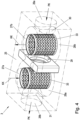
- Fig.2 the mixing unit 3 of a first embodiment in a perspective view
- Fig.3 a Flow pattern of the operating medium within the mixing unit 3 from Fig.2 in top view
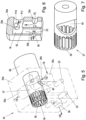
- Fig.4 shows a mixing unit 3 in an alternative embodiment in a perspective view.
- the mixing unit 3 can have a housing 25 made of a suitable material, for example a steel or aluminum alloy or plastic, in which suitable flow channels are provided for guiding the operating medium.
- At least one test item circuit inlet connection 26a and at least one test item circuit outlet connection 26b are provided on the mixing unit 3 for the fluidic integration of the mixing unit 3 into the test item circuit PK of the test item P. This means that the mixing unit 3 can be easily integrated into an existing test item circuit PK of a test item P on the test bench without structural changes to the test bench being necessary.
- connecting and sealing elements not shown can also be provided on the mixing unit 3 in order to enable the simplest and most leak-free connection possible, e.g. of a pipe or a hose of the test item circuit PK to the test item circuit inlet connection 26a and the test item circuit outlet connection 26b of the mixing unit 3.
- the test item circuit inlet connection 26a and the test item circuit outlet connection 26b are fluidically connected within the mixing unit 3 via the mixing area 28 in order to form part of the test item circuit PK.
- Operating medium can thus flow within the mixing unit 3 from the test item circuit inlet connection 26a via the mixing area 28 to the test item circuit outlet connection 26b, as in Fig.2-Fig.4 indicated by the two arrows and as in Fig.3 can be seen from the flow.
- the mixing area 28 is understood to mean the entire area within the mixing unit 3 in which the operating medium from the conditioning circuit KK and the operating medium from the test specimen circuit PK are in contact.
- At least one conditioning unit inlet connection 27a and at least one conditioning unit return connection 27b are provided on the mixing unit 3 for connecting the mixing unit 3 to the conditioning unit 2 of the conditioning system 1.
- the connection can be made, for example, via a return line RL and one or more inlet lines ZL, ZLa-ZLc, for example one inlet line ZLi per partial flow line ( Fig.1a ) or a common supply line ZL ( Fig.1b ). If there are several inlet lines ZLa-ZLc, these can be combined into a common collecting line SL before the mixing unit 3 or several conditioning unit inlet connections 27a could be provided, each of which can be connected to a inlet line ZLa-ZLc.
- the preconditioned operating medium from the partial flows can be combined into one flow by a collecting line SL in the mixing unit 3.
- the at least one conditioning unit inlet connection 27a and the at least one conditioning unit return connection 27b are also fluidically connected within the mixing unit 3 via the mixing area 28 in order to form part of the conditioning circuit KK (see Fig.1a , 1b ) for the operating medium.
- the preconditioned operating medium which is supplied to the mixing unit 3 from the conditioning unit 2
- the flow of the operating medium of the conditioning circuit KK is thus directed in the opposite direction to the flow of the operating medium of the test item circuit PK, which ensures good mixing.
- the pressure loss in the test item circuit PK can be compensated for via the throttle point 29.
- connecting and sealing elements can be provided on the mixing unit 3 in order to enable a connection that is as leak-free as possible, e.g. of a pipe or a hose of the conditioning circuit KK to the conditioning unit inlet connection 27a and the conditioning unit outlet connection 27b of the mixing unit 3.
- a mixing area 28 is provided in the mixing unit 3, in which the operating medium of the test item circuit PK can be mixed with the conditioned operating medium from the conditioning circuit KK in order to condition the operating medium in the test item circuit PK to the specified target temperature.
- the mixing area 28 preferably has at least one essentially annular mixing chamber 28a, as shown in particular in Fig.3 is apparent.
- annular is to be understood as meaning essentially any ring shape, for example a cylindrical ring, torus, etc.
- the conditioning unit return connection 27b is preferably arranged on the mixing unit 3 in such a way that it opens into the mixing area 28 between the test circuit inlet connection 26a and the conditioning unit inlet connection 27a.
- the conditioning unit return connection 27b opens into the mixing area 28, for example, between the test circuit inlet connection 26a and the annular mixing chamber 28a.
- a throttle point 29 can be provided between the conditioning unit inlet connection 27a and the conditioning unit return connection 27b.
- the throttle point 29 is arranged, for example, between the annular mixing chamber 28a and the conditioning unit return connection 27b and is designed as a fixed constriction with an unchangeable flow cross-section.
- the throttle point 29 allows the flow of the operating medium between the conditioning unit inlet connection 27a and the conditioning unit return connection 27b, a differential pressure is generated which counteracts the differential pressure in the flow of the operating medium in the test item circuit PK.
- a higher flow rate (volume flow rate or mass flow rate) of the operating medium in the conditioning circuit KK relative to the flow rate (volume flow rate or mass flow rate) in the test item circuit PK e.g. via a preferably controllable pump 15 and/or bypass line 16 with valve 17
- the pressure loss generated by the mixing unit 3 in the test item circuit PK can thus be reduced or preferably completely compensated or set to a specific value.
- the flow rate (volume flow rate or mass flow rate) in the conditioning circuit KK is preferably higher than the flow rate (volume flow rate or mass flow rate) in the test item circuit PK, for example 5-20%, in particular approx. 10% higher.
- the operating medium of the test item circuit PK in the mixing unit 3 can advantageously be exchanged essentially completely and replaced by conditioned operating medium from the conditioning circuit KK.
- the temperature of the operating medium in the area of at least one conditioning unit inlet connection 27a eg in the collecting line SL - Fig.1a or in the supply line ZL - Fig.1b ) therefore preferably corresponds essentially to the temperature of the operating medium in the region of the test object circuit outlet connection 26b.
- the temperature in the region of the at least one conditioning unit inlet connection 27a can therefore also be used as the target temperature T_TARGET and actual temperature T_ACTUAL.
- the flow cross-section at the throttle point 29 can also be changed (alternatively or in addition to controlling the flow in the conditioning circuit KK in the conditioning unit 2).
- an adjustable orifice can be provided for this purpose, by means of which the flow cross-section of the throttle point 29 can be changed.
- the adjustable orifice could be manually adjustable, but preferably an electrically controllable actuator A (see Fig.1b ) for adjusting the aperture, which can be controlled, for example, by the conditioning unit control unit 20 and/or by the test bench control unit 21.
- the control or regulation of the flow of the operating medium of the conditioning circuit KK can, as mentioned, be carried out via a control unit (e.g.
- a suitable controller e.g. PID controller
- a known pre-control of the manipulated variable X_STELL can also be implemented in the control system.
- the flow could also be controlled, for example, via a pump 15 with a variable delivery rate, e.g. via a pump 15 with an adjustable pump speed.
- the control of the adjustable orifice for adjusting the flow cross-section could also be controlled, for example, via a separate control unit and/or via the test bench control unit 21 or the conditioning unit control unit 20. If the adjustable orifice is closed at the throttle point 29, the pump 15 of the conditioning unit 2 can also be used, for example, to pump the operating medium in the test object circuit PK. In this case, a separate pump in the test object circuit PK could also be dispensed with.
- an inlet opening 30 of the test specimen circuit inlet connection 26a which opens from the outside into the annular mixing chamber 28a
- an outlet opening 31 of the test specimen circuit outlet connection 26b which opens from the outside into the annular mixing chamber 28a
- the at least one conditioning unit inlet connection 27a extends into a central region 32 of the mixing unit 3 and opens from the inside into the annular mixing chamber 28a, preferably in the region of the inlet opening 30 of the test specimen circuit inlet connection 26a.
- At least one temperature sensor 23 for measuring the actual temperature T_IST of the operating medium can be provided on the mixing unit 3.
- a temperature sensor 23 is provided in the area of the conditioning unit inlet connection 27a, a temperature sensor 23 in the area of the test circuit inlet connection 26a and a temperature sensor 23 in the area of the test circuit outlet connection 26b, as in Fig.3 is indicated.
- the recorded actual temperatures T _IST can be transferred to a control unit (eg test bench control unit 21 or conditioning unit control unit 20) for adjusting the target temperature T_TARGET in the test item circuit PK.
- Fig.4 an alternative embodiment of the mixing unit 3 is shown. At least one test circuit inlet connection 26a, at least one test circuit outlet connection 26b, at least one conditioning unit inlet connection 27a and at least one conditioning unit return connection 27a are provided on the mixing unit 3.
- Two essentially ring-shaped mixing chambers 28a, 28b are provided in the mixing area 28, which preferably communicate with each other radially.
- a throttle point 29 is preferably provided between the annular chambers 28a, 28b.
- the throttle point 29 could again have a fixed flow cross-section or an adjustable orifice (not shown) with an actuator A could be provided for adjusting the flow cross-section, as in Fig.1b is indicated.
- the conditioning unit inlet connection 27a preferably opens in the axial direction essentially centrally into the first mixing chamber 28a and the test piece circuit outlet connection 26b preferably opens radially into the first mixing chamber 28a.
- the conditioning unit return connection 27b preferably opens in the axial direction essentially centrally into the second mixing chamber 28b and the test piece circuit inlet connection 26a preferably opens radially into the second mixing chamber 28b.
- an inlet opening 30 of the test piece circuit inlet connection 26a which opens from the radial outside into the second annular mixing chamber 28b
- an outlet opening 31 of the test piece circuit outlet connection 26b which opens from the radial outside into the first annular mixing chamber 28a
- the inlet opening 30 and the outlet opening 31 are advantageously aligned, as shown.
- the at least one sieve element 33 is provided in the mixing area 28. This can generate turbulence in the flow, which improves the mixing.
- the at least one sieve element 33 can also serve as a type of dirt filter, so that, for example, deposits or dirt particles from the test item circuit PK cannot get into the conditioning circuit KK.
- at least one sieve element 33 with a sufficiently small mesh size can be provided at least in the area of the conditioning unit return connection 27b.
- various structural designs can be used as the sieve element 33, for example perforated sheets, wire mesh, metal grids, etc.
- each mixing chamber 28a, 28b could initially have a preferably cylindrical Recesses can be provided, e.g. drilled or milled into the housing 25.
- the ring-shaped sieve elements 33 can then be inserted in a suitable manner.
- the ring-shaped mixing chamber 28a, 28b is thus formed between the inner circumferential surface of the cylindrical opening and the outer circumferential surface of the ring-shaped sieve element 33.
- the preconditioned operating medium can flow from the conditioning circuit KK via the conditioning unit inlet connection 27a essentially in the axial direction into the cylindrical interior of the annular sieve element 33 and through the openings of the annular sieve element 33 in the radial direction into the annular mixing chamber 28a. From the annular mixing chamber 28a, the operating medium can flow further against the flow direction of the test circuit PK through the throttle point 29 into the second annular mixing chamber 28b.
- the operating medium can flow essentially in the opposite direction to that in the first mixing chamber 28a, first radially through the openings in the sieve element 33 into the interior of the sieve element 33 and then in the axial direction to the conditioning unit return connection 27b, as indicated by the arrows in Fig.4 is indicated.
- the operating medium of the test specimen circuit PK can flow essentially in the opposite direction through the mixing region 28, as indicated by the corresponding arrows.
- a valve unit 34 for use in the conditioning unit 2 is shown in an advantageous embodiment.
- Fig.6 shows a sectional view of the valve housing 34a of the valve unit 34 from Fig.5.
- Fig.7 shows a mixing element 37 of the valve unit 34 from Fig.5 .
- the valve unit 34 can be used to distribute a main fluid flow HS of a (liquid or gaseous) operating medium to at least two partial fluid flows TS and/or to mix at least two partial fluid flows of an operating medium or several different operating media to form a main fluid flow HS.
- the valve unit 34 can therefore advantageously be used, for example, in the Fig.1b shown conditioning unit 2 can be used to combine the three partial flow lines 7a-7c into a conditioning manifold KSL.
- the valve unit 34 could additionally or alternatively also be used in the conditioning unit 2 at the junction 8 to distribute the main flow line 6 to the three partial flow lines 7a-7c.
- the valve unit 34 could also be provided for other purposes, for example to produce a mixture of different gases in the main fluid flow HS, which are fed to the valve unit 34 via the partial fluid flows TS.
- a synthesis gas could be produced from oxygen O2, nitrogen N2 and carbon dioxide CO2.
- the valve unit 34 or the valve housing 34a has at least one main fluid flow connection 36 for the main fluid flow HS and at least one partial fluid flow connection 35a-35c for each partial fluid flow TS, which communicate fluidically via a mixing chamber M provided in the valve unit 34.
- the valve unit according to Fig.1b for mixing the partial fluid flows TS of the partial flow lines 7a-7c for example, the first partial flow line 7a can be connected to the first partial fluid flow connection 35a, the second partial flow line 7b to the second partial fluid flow connection 35b and the third partial flow line 7c to the third partial fluid flow connection 35c.
- the conditioning unit collecting line KSL can be connected to the main fluid flow connection 36.
- a movable mixing element 37 is provided for controlling the flow, which can be driven by a drive unit 38. Depending on the position of the mixing element 37, a specific mixing ratio of the partial fluid flows can be set.
- the mixing element 37 is designed as a rotatable rotor and the drive unit 38 is designed as an electrically actuated actuator, as in Fig.5
- the drive unit 38 can be controlled, for example, by a suitable control unit in order to mix the partial fluid streams TS with a certain mixing ratio (or to distribute them in a certain ratio).
- the valve unit 34 can, for example, be controlled by the conditioning unit control unit 20 with a specific control variable X_STELL in order to set a mixing ratio of the operating medium from the partial flow lines 7a-7c so that the desired target temperature T_SOLL is reached in the test object circuit PK.
- the mixing chamber M can, for example, be at least partially cylindrical and the mixing element 37 or the rotor can, for example, have a hollow cylinder which is rotatable in the mixing chamber M (see Fig.5 ).
- a control opening 40 is preferably provided on the outer circumferential surface of the hollow cylinder, which connects the outer circumferential surface of the hollow cylinder with the inner circumferential surface.
- the control opening 40 can be a cylindrical bore, for example, but can also have a different shape. In the example shown, the control opening 40 is designed as a type of notch, for example.
- the control opening 40 extends in the circumferential direction over a predetermined area, which essentially depends on the structural design of the valve unit 34, in particular on the relative arrangement of the arrangement of the inlet openings 41a-41c of the partial fluid flow connections 35a-35c in the mixing chamber M, wherein in Fig.6 only the inlet openings 41a, 41c are visible.
- the control opening 40 can extend over 90-180° in the circumferential direction extend.
- the length of the control opening 40 preferably corresponds to the length of the inlet openings of the partial fluid flow connections 35a-35c.
- the control opening 40 By rotating the rotor or hollow cylinder by means of the drive unit 38, the control opening 40 can be brought at least partially into line with at least one inlet opening 41a-41c of the partial fluid flow connections 35a-35c opening into the mixing chamber M.
- the valve unit 34 as a mixing valve (as in Fig.1b )
- a specific mixing ratio of the partial fluid flows TS of the operating medium (or the different operating media) in the main fluid flow HS can be set.
- the rotor can preferably be rotated continuously between a first position in which the control opening 40 communicates exclusively with the inlet opening 41a of the first partial fluid flow connection 35a, a second position in which the control opening 40 communicates exclusively with the inlet opening 41b of the second partial fluid flow connection 35b and a third position (vertically downwards) in which the control opening 40 communicates exclusively with the inlet opening 41c of the third partial fluid flow connection 35c.
- the inlet openings 41b, 41c of the second and third partial fluid flow connections 35b, 35c are closed so that 100% of the flow can flow via the first partial fluid flow connection 35a.
- the inlet openings 41a, 41c of the first and third partial fluid flow connections 35a, 35c are closed so that 100% of the flow can flow via the second partial fluid flow connection 35b
- the inlet openings 41a, 41b of the first and second partial fluid flow connections 35a, 35b are closed so that 100% of the flow can flow via the third partial fluid flow connection 35c.
- the control opening 40 is in a position between the first and third positions, the first partial fluid flow and the third partial fluid flow are mixed in a specific ratio.
- the control opening 40 is in a position between the second and third positions, the second partial fluid flow and the third partial fluid flow are mixed in a specific ratio.
- the respective mixing ratio depends essentially on the size and geometry of the control opening 40 as well as on the size and geometry of the inlet openings 41a-41c of the partial fluid flow connections 35a-35c.
- At least one swirl recess 39 can preferably also be provided on the outer peripheral surface of the hollow cylinder, which connects the outer peripheral surface of the hollow cylinder with the inner peripheral surface.
- a swirl recess 39 can preferably also be provided on the outer peripheral surface of the hollow cylinder, which connects the outer peripheral surface of the hollow cylinder with the inner peripheral surface.
- several turbulence recesses 39 are provided in the circumferential direction on the hollow cylinder.
- the turbulence recesses 39 are arranged in the axial direction in a section of the hollow cylinder which is located in an area of an inlet 42 of the main fluid flow connection 36 in the mixing chamber M. This can cause turbulence in the flow, whereby an improved mixing of the partial fluid flows TS can be achieved.
- the recesses 39 can be designed, for example, as elongated holes, the main axes of which run, for example, parallel to the axis of the hollow cylinder.
- valve unit 34 shown is only an example and other designs would of course also be conceivable.
- the mixing chamber M and the mixing element 37 do not have to be cylindrical, but could also have a different shape.
- the mixing behavior of the valve unit 34 can be adapted to certain boundary conditions.
Landscapes
- Chemical & Material Sciences (AREA)
- Chemical Kinetics & Catalysis (AREA)
- Physics & Mathematics (AREA)
- General Physics & Mathematics (AREA)
- Dispersion Chemistry (AREA)
- Engineering & Computer Science (AREA)
- Automation & Control Theory (AREA)
- Testing Resistance To Weather, Investigating Materials By Mechanical Methods (AREA)
- Testing Of Devices, Machine Parts, Or Other Structures Thereof (AREA)
- Control Of Temperature (AREA)
- Air Conditioning Control Device (AREA)
Description
- Die Erfindung betrifft eine Mischungseinheit für ein Konditioniersystem eines Prüfstands, zur Konditionierung eines Betriebsmediums eines Prüflingskreislaufs eines am Prüfstand aufgebauten Prüflings auf eine vorgegebene Soll-Temperatur sowie eine Konditioniereinheit für ein Konditioniersystem eines Prüfstands zur Konditionierung eines Betriebsmediums eines Prüflingskreislaufs eines am Prüfstand aufgebauten Prüflings auf eine vorgegebene Soll-Temperatur. Weiters betrifft die Erfindung ein Konditioniersystem für einen Prüfstand zur Konditionierung eines Betriebsmediums eines Prüflingskreislaufs eines am Prüfstand aufgebauten Prüflings auf eine vorgegebene Soll-Temperatur und einen Prüfstand mit einem Prüfling und mit einem Konditioniersystem zur Konditionierung eines Betriebsmediums eines Prüflingskreislaufs des Prüflings auf eine vorgegebene Soll-Temperatur. Zudem betrifft die Erfindung ein Verfahren zum Konditionieren eines Betriebsmediums eines Prüflingskreislaufs eines Prüflings auf einem Prüfstand auf eine vorgegebene Soll-Temperatur.
- Auf Prüfständen können für bestimmte Prüfversuche bekannterweise Konditioniersysteme verwendet werden, um bestimmte flüssige oder gasförmige Betriebsmedien eines aufgebauten Prüflings auf eine gewünschte Temperatur zu konditionieren. Beispielsweise werden als Prüflinge ganze Fahrzeuge, Teilsysteme von Fahrzeugen oder einzelne Komponenten von Fahrzeugen geprüft. Ein Teilsystem eines Fahrzeugs ist z.B. ein Antriebsstrang, der eine oder mehrere Komponenten, wie Antriebsaggregate, Getriebe, usw., umfassen kann. Eine Komponente kann beispielsweise ein Antriebsaggregat wie z.B. ein Verbrennungsmotor, Elektromotoren, Kombinationen von Verbrennungsmotoren und Elektromotoren (sogenannte Hybridantriebe) sein. Komponenten können aber beispielsweise auch Brennstoffzellen, Batterien, Getriebe usw. sein. Jeder Prüfling weist üblicherweise zumindest einen Prüflingskreislauf für ein Betriebsmedium auf, wie z.B. ein Kühlmittel, Kraftstoff, Schmieröl, etc. Während des Betriebs des Prüflings am Prüfstand zirkuliert das Betriebsmedium im Prüflingskreislauf, wobei üblicherweise ein Wärmeeintrag in das Betriebsmedium erfolgt. Oftmals ist es dabei gewünscht, bestimmte zeitliche Temperaturverläufe des Betriebsmediums im Prüflingskreislauf am Prüfstand möglichst genau und möglichst rasch einzustellen. Beispielsweise kann es gewünscht sein, einen zuvor unter realen Bedingungen (beispielsweise in einem realen Fahrzeug bei einer Fahrt auf einer bestimmten Strecke) aufgezeichneten Temperaturverlauf eines Betriebsmediums des Prüflings am Prüfstand nachzubilden oder auch einen zeitgleich simulierten Temperaturverlauf. Es kann auch gewünscht sein, die Temperatur auf einem möglichst konstanten Niveau zu halten. Insbesondere rasche Temperaturänderungen des Betriebsmediums am Prüfstand durch ein Konditioniersystem können bisher aber nur unzureichend eingeregelt werden, was im Wesentlichen an der relativ hohen thermischen Trägheit der verwendeten Betriebsmedien liegt.
- Konditioniersysteme und Komponenten von Konditioniersystemen sind beispielsweise aus
WO 2019/183658 A1 ,WO 2019/149792 A1 ,EP 3 293 504 A1 ,DE 10 2009 013449 A1 oder ausUS 2019/091641 A1 bekannt. - Es ist daher die Aufgabe der Erfindung, eine Vorrichtung und ein Verfahren bereitzustellen, die es ermöglichen, ein Betriebsmedium in einem Prüflingskreislauf eines Prüflings auf einem Prüfstand möglichst rasch auf eine gewünschte Temperatur zu konditionieren.
- Erfindungsgemäß wird die Aufgabe mit einer Konditioniereinheit dadurch gelöst, dass an der Konditioniereinheit zumindest ein Mischungseinheits-Zulaufanschluss und zumindest ein Mischungseinheits-Ablaufanschluss, zur Verbindung der Konditioniereinheit mit einer in den Prüflingskreislauf fluidisch integrierbaren Mischungseinheit vorgesehen sind, wobei der zumindest eine Mischungseinheits-Zulaufanschluss und der zumindest eine Mischungseinheits-Ablaufanschluss innerhalb der Konditioniereinheit fluidisch verbunden sind, um einen Teil eines Konditionierkreislaufs für das Betriebsmedium auszubilden, wobei sich eine mit dem zumindest einen Mischungseinheits-Zulaufanschluss verbundene Hauptstromleitung des Konditionierkreislaufs in der Konditioniereinheit in zumindest zwei Teilstromleitungen aufteilt, wobei jede Teilstromleitung mit dem zumindest einen Mischungseinheits-Ablaufanschluss verbunden ist, wobei das Betriebsmedium in einer Teilstromleitung auf eine vorgegebene Konditionierungs-Temperatur konditionierbar ist und die zumindest eine weitere Teilstromleitung von unkonditioniertem Betriebsmedium mit einer relativ zur Konditionierungs-Temperatur höheren oder niedrigeren Neutral-Temperatur durchströmbar ist, wobei ein Durchfluss des Betriebsmediums in den zumindest zwei Teilstromleitungen in Abhängigkeit der vorgegebenen Soll-Temperatur im Prüflingskreislauf einstellbar ist. Durch Einstellen des Durchflusses kann in Abhängigkeit der vorgegebenen Soll-Temperatur ein bestimmtes Mischungsverhältnis von Betriebsmedium aus den zumindest zwei Teilstromleitungen erzeugt werden, sodass die Soll-Temperatur möglichst rasch erreicht werden kann.
- Vorteilhafte Ausgestaltungen der Konditioniereinheit sind in den abhängigen Ansprüchen 2 bis 11 angegeben.
- Weiters wird die Aufgabe mit einem Verfahren dadurch gelöst, dass eine Mischungseinheit in den Prüflingskreislauf fluidisch integriert wird, um einen Teil des Prüflingskreislaufs auszubilden, wobei zu konditionierendes Betriebsmedium des Prüflingskreislaufs der Mischungseinheit über zumindest einen Prüflingskreis-Zulaufanschluss zugeführt wird und auf die vorgegebene Soll-Temperatur konditioniertes Betriebsmedium über zumindest einen Prüflingskreis-Ablaufanschluss von der Mischungseinheit abgeführt wird, wobei der Mischungseinheit über zumindest einen Konditioniereinheits-Zulaufanschluss zumindest Betriebsmedium mit einer vorgegebenen Konditionierungs-Temperatur und Betriebsmedium mit einer relativ dazu höheren oder niedrigeren Neutral-Temperatur zugeführt wird, das in einem innerhalb der Mischungseinheit vorgesehenen Mischbereich mit dem zugeführten Betriebsmedium des Prüflingskreislaufs gemischt wird und über zumindest einen Konditioniereinheits-Rücklaufanschluss von der Mischungseinheit abgeführt wird, wobei ein Durchfluss des Betriebsmediums mit der Konditionierungs-Temperatur und ein Durchfluss des Betriebsmediums mit der Neutral-Temperatur in Abhängigkeit der vorgegebenen Soll-Temperatur eingestellt wird.
- Vorteilhafte Ausgestaltungen des Verfahrens sind in den abhängigen Ansprüchen 13 bis 16 angegeben.
- In vorteilhafter Weise kann die Aufgabe weiters mit einer Mischungseinheit dadurch gelöst werden, dass in der Mischungseinheit ein Mischbereich vorgesehen ist, in dem Betriebsmedium des Prüflingskreislaufs mit vorkonditioniertem Betriebsmedium aus einem Konditionierkreislauf mischbar ist, um das Betriebsmedium im Prüflingskreislauf auf die vorgegebene Soll-Temperatur zu konditionieren, wobei an der Mischungseinheit zur fluidischen Integration der Mischungseinheit in den Prüflingskreislauf zumindest ein Prüflingskreis-Zulaufanschluss und zumindest einen Prüflingskreis-Ablaufanschluss vorgesehen sind, die über den Mischbereich fluidisch miteinander verbunden sind, um einen Teil des Prüflingskreislaufs auszubilden, wobei an der Mischungseinheit zur Verbindung der Mischungseinheit mit einer Konditioniereinheit des Konditioniersystems zumindest ein Konditioniereinheits-Zulaufanschluss und zumindest ein Konditioniereinheits-Rücklaufanschluss vorgesehen sind, die über den Mischbereich fluidisch miteinander verbunden sind, um einen Teil des Konditionierkreislaufs für das Betriebsmedium auszubilden. Dadurch kann ein sehr homogenes Gemisch erzeugt werden und ein Druckverlust im Prüflingskreislauf möglichst geringgehalten werden.
- Die gegenständliche Erfindung wird nachfolgend unter Bezugnahme auf die
Figuren 1a bis 7 näher erläutert, die beispielhaft, schematisch und nicht einschränkend vorteilhafte Ausgestaltungen der Erfindung zeigen. Dabei zeigt -
Fig.1a ein Konditioniersystem der Erfindung in einer vorteilhaften Ausgestaltung, -
Fig.1b ein Konditioniersystem der Erfindung in einer alternativen Ausgestaltung -
Fig.2 eine Mischungseinheit in einer vorteilhaften Ausgestaltung, -
Fig.3 einen Strömungsverlauf in der Mischkammer der Mischungseinheit, -
Fig.4 eine Mischungseinheit in einer alternativen Ausgestaltung und -
Fig.5 eine Ventileinheit in einer vorteilhaften Ausgestaltung, -
Fig.6 eine Schnittdarstellung eines Ventilgehäuses der Ventileinheit und -
Fig.7 ein Mischelement der Ventileinheit. -
Fig.1a zeigt eine schematische Darstellung eines erfindungsgemäßes Konditioniersystems 1 auf einem Prüfstand in einer vorteilhaften Ausführungsform. Das Konditioniersystem 1 weist eine Konditioniereinheit 2 und eine Mischungseinheit 3 auf, die fluidisch miteinander verbunden sind, um einen Konditionierkreislauf KK für ein fluides Betriebsmedium auszubilden. Unter einem fluiden Betriebsmedium ist hierbei ein geeignetes gasförmiges oder flüssiges Medium zu verstehen. Beispielsweise kann als Betriebsmedium ein Kühlmittel, ein Kraftstoff, ein Öl, Luft, etc. vorgesehen sein. Unter "fluidisch verbunden" ist im Rahmen der Erfindung eine strömungsmechanische Verbindung zu verstehen, beispielsweise über geeignete Rohre, Leitungen, etc. Die Mischungseinheit 3 kann in einen Prüflingskreislauf PK eines auf einem Prüfstand aufgebauten Prüflings P fluidisch integriert werden, in welchem dasselbe Betriebsmedium zirkuliert. Die Art des verwendeten Betriebsmediums im Konditionierkreislauf KK hängt dabei vom verwendeten Betriebsmedium im Prüflingskreislauf PK des Prüflings P ab. Wie eingangs erwähnt, kann als Prüfling P beispielsweise ein Getriebe wie z.B. ein Schaltgetriebe, Automatikgetriebe oder ein Achsgetriebe vorgesehen sein, ein Antriebsaggregat wie z.B. ein Verbrennungsmotor, Elektromotor, ein Hybridantrieb, ein Energiespeicher wie z.B. eine Batterie oder ein Energiewandler wie z.B. eine Brennstoffzelle, etc. Für die Erfindung ist es aber unerheblich, welche Art von Prüfling P verwendet wird. Grundsätzlich kann jeder Prüfling P mit einem Prüflingskreislauf PK mit Betriebsmedium verwendet werden. Bei mehreren Betriebsmedien des Prüflings können am Prüfstand natürlich auch mehrere solcher erfindungsgemäßen Konditioniersysteme 1 vorgesehen sein. Um den Prüfling P am Prüfstand entsprechend eines Prüfversuchs zu steuern, ist in bekannter Weise in der Regel eine Prüfstandssteuerungseinheit 21 vorgesehen. - Im Prüflingskreislauf PK kann natürlich auch eine (nicht dargestellte) Pumpe zur Förderung des Betriebsmediums vorgesehen sein, die Teil des Prüfstands oder auch Teil des Prüflings P sein kann. Natürlich können auch weitere Komponenten, wie z.B. Wärmetauscher, Ventile, Sensoren, Drosseln, etc. im Prüflingskreislauf PK vorgesehen sein, die jedoch für die Erfindung unerheblich sind. Die Mischungseinheit 3 kann, so wie in
Fig.1 dargestellt, in Strömungsrichtung des Betriebsmediums nach dem Prüfling P im Prüflingskreislauf PK integriert werden. Die Mischungseinheit 3 kann aber auch in Strömungsrichtung des Betriebsmediums vor dem Prüfling P vorgesehen sein, wie inFig.1 durch den gestrichelten Prüfling P angedeutet ist. - Das Temperaturverhalten des Betriebsmediums soll am Prüfstand mit Hilfe des Konditioniersystems 1 nachgebildet werden. Insbesondere soll mit dem Konditioniersystem 1 gemäß der Erfindung der Wärmeeintrag des Prüflings P in den Prüflingskreislauf PK nachgebildet werden, der sich aus dem Betrieb des Prüflings P ergibt. Der Prüfling P kann dazu am Prüfstand tatsächlich bestimmungsgemäß betrieben werden, sodass er selbst Arbeit verrichtet, durch die das Betriebsmedium im Prüflingskreislauf PK erwärmt wird. Das Konditioniersystem 1 könnte dabei beispielsweise genutzt werden, um einen höheren oder geringeren Wärmeeintrag des Prüflings P zu simulieren. Der Prüfling P kann aber auch lediglich dazu genutzt werden, um den durch den Prüfling P verursachten Druckverlust im Prüflingskreislauf PK möglichst realitätsnah abbilden zu können. Der Prüfling P wird in diesem Fall nicht selbst betrieben, verursacht also keinen Wärmeeintrag in das Betriebsmedium des Prüflingskreislaufs PK, sondern sein Wärmeeintrag wird durch das erfindungsgemäße Konditioniersystem 1 emuliert.
- Dazu werden vorkonditioniertes Betriebsmedium aus dem Konditionierkreislauf KK und das Betriebsmedium des Prüflingskreislaufs PK in der Mischungseinheit 3 derart gemischt, dass eine vorgegebene Soll-Temperatur T_SOLL des Betriebsmediums im Prüflingskreislauf PK stromabwärts der Mischeinheit 3 eingestellt wird. Die Vorkonditionierung des Betriebsmediums im Konditionierkreislauf KK wird von der Konditioniereinheit 2 durchgeführt, wie nachfolgend näher erläutert wird. Vorteilhafte Ausgestaltungen der Mischungseinheit 3 werden anhand
Fig.2 +Fig.3 sowieFig.4 noch näher beschrieben. - Allgemein sind an der Konditioniereinheit 2 zumindest ein Mischungseinheits-Zulaufanschluss 4 und zumindest ein Mischungseinheits-Ablaufanschluss 5 zur Verbindung der Konditioniereinheit 2 mit der Mischungseinheit 3 vorgesehen. Im dargestellten Beispiel gemäß
Fig.1a sind beispielsweise drei Mischungseinheits-Ablaufanschlüsse 5a-5c vorgesehen. Der Mischungseinheits-Zulaufanschluss 4 ist innerhalb der Konditioniereinheit 2 fluidisch mit den drei Mischungseinheits-Ablaufanschlüssen 5a-5c verbunden, um einen Teil des Konditionierkreislaufs KK für das Betriebsmedium auszubilden. Allgemein teilt sich eine mit dem Mischungseinheits-Zulaufanschluss 4 verbundene Hauptstromleitung 6 des Konditionierkreislaufs KK innerhalb der Konditioniereinheit 2 in zumindest zwei Teilstromleitungen 7a+7c (oder 7b+7c) auf, beispielsweise an einem Verteilerknoten 8. - Allgemein ist das Betriebsmedium in einer der zumindest zwei Teilstromleitungen 7a, 7b auf eine vorgegebene Konditionierungs-Temperatur T1, T2 konditionierbar und die zumindest eine weitere Teilstromleitung 7c ist von unkonditioniertem Betriebsmedium mit einer relativ zur Konditionierungs-Temperatur T1, T2 höheren oder niedrigeren Neutral-Temperatur T3 durchströmbar. Die Ausführungsform mit einer gegenüber der Neutral-Temperatur T3 höheren Konditionierungs-Temperatur T1 kann verwendet werden, wenn nur ein Erwärmen des Betriebsmediums im Prüflingskreislauf PK erwünscht ist. Die Ausführungsform mit einer gegenüber der Neutral-Temperatur T3 niedrigeren Konditionierungs-Temperatur T2 kann verwendet werden, wenn ein Kühlen des Betriebsmediums im Prüflingskreislauf PK erwünscht ist. Zur Konditionierung auf die relativ zur Neutral-Temperatur T3 höhere oder niedrigere Konditionierungs-Temperatur T1, T2 kann eine geeignete Temperiereinheit 9a, 9b in der jeweiligen Teilstromleitung 7a, 7b vorgesehen sein, wie nachfolgend noch näher erläutert wird.
- Im gezeigten Beispiel in
Fig.1a teilt sich die Hauptstromleitung 6 innerhalb der Konditioniereinheit 2 in drei Teilstromleitungen 7a, 7b, 7c, es kann somit eine Erwärmung des Betriebsmediums in der ersten Teilstromleitung 7a erfolgen und eine Kühlung des Betriebsmediums in der zweiten Teilstromleitung 7b. In der Hauptstromleitung 6 kann eine, vorzugsweise steuer- bzw. regelbare Pumpe 15 zur Förderung des Betriebsmediums im Konditionierkreislauf KK vorgesehen sein, es kann aber auch jeweils eine (nicht dargestellte) Pumpe in den Teilstromleitungen 7a-7c vorgesehen sein. Weiters kann auch eine Bypassleitung 16 für das Betriebsmedium vorgesehen sein, die die Hauptstromleitung 6 stromaufwärts der Pumpe 15 mit der Hauptstromleitung 6 stromabwärts der Pumpe verbindet, um die Pumpe 15 zu überbrücken. In der Bypassleitung 16 kann ein steuerbares Ventil 17 vorgesehen sein, um einen durch die Mischungseinheit 3 verursachten Druckverlust Δp im Prüflingskreislauf PK zu verringern, vorzugsweise vollständig zu kompensieren, wie nachfolgend anhand der inFig.2-Fig.4 dargestellten Mischungseinheit 3 noch näher erläutert wird. Alternativ oder zusätzlich zur Bypassleitung 16 inkl. Ventil 17 kann auch eine Drosselstelle 29 mit einer verstellbaren Blende in der Mischungseinheit 3 vorgesehen sein, über die der Druckverlust kompensiert werden kann, wie ebenfalls anhandFig.2-Fig.4 noch näher erläutert wird. - Im Beispiel gemäß
Fig.1a ist jede Teilstromleitung 7a-7c innerhalb der Konditioniereinheit 2 mit jeweils einem Mischungseinheits-Ablaufanschluss 5a-5c verbunden. Die Mischungseinheits-Ablaufanschlüsse 5a-5c können wiederum z.B. über Zulaufleitungen ZLa-Zlc, mit der Mischungseinheit 3 verbunden werden, um das vorkonditionierte Betriebsmedium der Mischungseinheit 3 zuzuführen. Das Betriebsmedium kann in einer ersten Teilstromleitung 7a auf eine erste Konditionierungs-Temperatur T1 konditioniert werden und in einer zweiten Teilstromleitung 7b auf eine zweite Konditionierungs-Temperatur T2 konditioniert werden. Eine dritte Teilstromleitung 7c kann vom Betriebsmedium mit einer zwischen der ersten und zweiten Temperatur liegenden Neutral-Temperatur T3 durchströmt werden und wird vorzugsweise nicht separat konditioniert. Die Temperaturbereiche der Konditionierungs-Temperaturen T1, T2 hängen im Wesentlichen von den vorgegebenen Randbedingungen bzw. Anforderung an das Konditioniersystem 1 ab, wie z.B. von einer minimal bzw. maximal geforderten Soll-Temperatur T_SOLL des Betriebsmediums und/oder dem verwendeten Betriebsmedium. Die zwischen den Konditionierungs-Temperaturen T1, T2 liegende Neutral-Temperatur T3 hängt im Wesentlichen von der Temperatur des von der Mischungseinheit 3 rückströmenden Betriebsmediums ab. - Vorzugsweise ist in der Konditioniereinheit 2 in der ersten Teilstromleitung 7a zumindest eine erste Temperiereinheit 9a vorgesehen, um das Betriebsmedium auf die erste (hohe) Konditionierungs-Temperatur T1 zu konditionieren. Gleichfalls ist vorzugsweise in der zweiten Teilstromleitung 7b zumindest ein zweiter Temperiereinheit 9b vorgesehen, um das Betriebsmedium auf die zweite (niedrige) Konditionierungs-Temperatur T2 zu konditionieren. Als Temperiereinheit 9a, 9b können grundsätzlich alle Einrichtungen verwendet werden, die geeignet sind, das Betriebsmedium in der ersten und zweiten Teilstromleitung 7a, 7b auf die jeweils vorgesehenen Konditionierungs-Temperaturen T1, T2 zu konditionieren, wie z.B. Wärmetauscher, (z.B. elektrische) Heizeinrichtungen, Kühleinrichtungen, Wärmepumpen, Peltierelemente, usw. Beispielsweise können dazu an der Konditioniereinheit 2 zumindest ein Wärmequellen-Vorlaufanschluss 10a und zumindest ein Wärmequellen-Rücklaufanschluss 10b zum Anschluss einer Wärmequelle vorgesehen sein. Der Wärmequellen-Vorlaufanschluss 10a und der Wärmequellen-Rücklaufanschluss 10b können mit der als Wärmetauscher ausgebildeten ersten Temperiereinheit 9a fluidisch verbunden sein, um einen Teil eines Wärmequellen-Versorgungskreislaufs VK1 auszubilden.
- In analoger Weise können an der Konditioniereinheit 2 auch zumindest ein Wärmesenken-Vorlaufanschluss 11a und zumindest ein Wärmesenken-Rücklaufanschluss 11b zum Anschluss der Wärmesenke vorgesehen sein, die mit der als Wärmetauscher ausgebildeten zweiten Temperiereinheit 9b fluidisch verbunden sind, um einen Teil eines Wärmesenken-Versorgungskreislaufs VK2 auszubilden. Als Wärmequelle kann im Wesentlichen jede beliebige geeignete Einrichtung verwendet werden, mit der das Versorgungsmedium des Wärmequellen-Versorgungskreislaufs VK1 auf einer möglichst konstanten relativ hohen Versorgungstemperatur gehalten wird, beispielsweise im Bereich von 10K über der max. geforderten Soll-Temperatur. Analog kann als Wärmesenke im Wesentlichen jede beliebige geeignete Einrichtung verwendet werden, mit der das Versorgungsmedium des Wärmesenken-Versorgungskreislaufs VK2 auf einer möglichst konstanten relativ niedrigen Versorgungstemperatur gehalten wird, beispielsweise im Bereich von 10K unter der min. geforderten Soll-Temperatur. Als Versorgungsmedium kann beispielsweise das Betriebsmedium verwendet werden oder ein anderes geeignetes Medium.
- Die Wärmebereitstellung durch die Wärmequelle und Wärmesenke kann beispielsweise in einem separaten Versorgungsmodul 12 erfolgen, das eine autarke Einheit bildet, an welche die Konditioniereinheit 2 angeschlossen werden kann. Im Versorgungsmodul 12 können natürlich auch weitere (nicht dargestellte) hydraulische Komponenten für die Versorgungskreisläufe VK1, VK2 vorgesehen sein, beispielsweise Pumpen, Druckregeleinrichtungen, Ventile, Tanks, etc. Die Steuerung des Versorgungsmoduls 12 könnte beispielsweise durch eine Konditioniereinheits-Steuerungseinheit 20 erfolgen, die z.B. in der Konditioniereinheit 2 angeordnet sein kann. Die Steuerung des Versorgungsmoduls 12 könnte aber beispielsweise auch durch eine Prüfstands-Steuerungseinheit 21 des Prüfstands erfolgen, auf dem das Konditioniersystem 1 verwendet wird (wie durch die gestrichelte Verbindungslinie in
Fig.1 angedeutet ist). - Oftmals ist auf Prüfständen zur Bereitstellung von vorkonditionierten Versorgungsmedien aber ein zentrales Medienversorgungsystem, beispielsweise als Teil des Prüfstandsgebäudes vorgesehen. Über das zentrale Medienversorgungsystem können beispielsweise mehrere, auch verschiedenartige Prüfstände, mit einem oder mehreren vorkonditionierten Versorgungsmedien versorgt werden. Die Bereitstellung der vorkonditionierten Versorgungsmedien für die Versorgungskreisläufe VK1, VK2 der ersten und zweiten Temperiereinheiten 9a, 9b, insbesondere Wärmetauscher könnte in diesem Fall beispielsweise über Versorgungsleitungen L1, L2 des zentralen Medienversorgungsystems erfolgen, wie in
Fig.1a angedeutet ist. Auf ein separates Versorgungsmodul 12 kann in diesem Fall verzichtet werden. - Die Konditioniereinheit 2 ist dazu ausgebildet, einen Durchfluss des Betriebsmediums, z.B. Volumenstrom oder Massenstrom, in den drei Teilstromleitungen 7a-7c (bzw. allgemein zumindest zwei Teilstromleitungen 7a+7c oder 7b+7c) in Abhängigkeit der vorgegebenen Soll-Temperatur T_SOLL des Betriebsmediums im Prüflingskreislauf PK zu steuern, insbesondere zu regeln, sodass die Soll-Temperatur T_SOLL im Prüflingskreislauf PK möglichst rasch eingestellt werden kann. Dazu wird das vorkonditionierte Betriebsmedium aus den Teilstromleitungen 7a-7c der Konditioniereinheit 2 abhängig von der vorgegebenen Soll-Temperatur T_SOLL Prüflingskreislauf PK mit dem Betriebsmedium im Prüflingskreislauf PK gemischt, wobei das Mischen in der Mischungseinheit 3 erfolgt, insbesondere in einem Mischbereich 28 der Mischungseinheit 3, wie nachfolgend anhand
Fig.2-Fig.4 noch näher erläutert wird. Um den Konditionierkreislauf KK auszubilden kann die Konditioniereinheit 2 beispielsweise über eine oder mehrere geeignete Zulaufleitungen ZLa-ZLc und eine oder mehrerer geeignete Rücklaufleitungen RL mit der Mischungseinheit 3 verbunden sein. - An der Mischungseinheit 3 sind dazu zumindest ein Konditioniereinheits-Zulaufanschluss 27a und ein Konditioniereinheits-Rücklaufanschluss 27b vorgesehen. Der Konditioniereinheits-Rücklaufanschluss 27b kann über die Rücklaufleitung RL mit dem Mischungseinheits-Zulaufanschluss 4 der Konditioniereinheit 2 verbunden sein. Im gezeigten Beispiel in
Fig.1a ist an jeden Mischungseinheits-Ablaufanschluss 5a-5c der Konditioniereinheit 2 eine Zulaufleitung ZLa-ZLc angeschlossen. Wenn an der Mischungseinheit 3 ein einziger Konditioniereinheits-Zulaufanschluss 27a vorgesehen ist, können die Zulaufleitungen ZLa-ZLc vorzugsweise unmittelbar vor der Mischungseinheit 3 zu einer gemeinsamen Sammelleitung SL zusammengeführt sein, wie inFig.1a angedeutet ist. Die gemeinsame Sammelleitung SL kann dann mit dem Konditioniereinheits-Zulaufanschluss 27a verbunden sein. An der Mischungseinheit 3 könnten aber auch mehrere (nicht dargestellte) Konditioniereinheits-Zulaufanschlüsse 27a vorgesehen sein, beispielsweise drei Konditioniereinheits-Zulaufanschlüsse 27a (bzw. ein Konditioniereinheits-Zulaufanschluss 27a je Zulaufleitung ZLa-ZLc). In diesem Fall könnte jeder Mischungseinheits-Ablaufanschluss 5a-5c über eine Zulaufleitung ZLa-ZLc mit einem Konditioniereinheits-Zulaufanschluss verbunden sein. Die mehreren Konditioniereinheits-Zulaufanschlüsse 27a könnten dann in der Mischungseinheit 3 zu einer Sammelleitung SL zusammengeführt sein, welche wiederum in den Mischbereich 28 der Mischungseinheit 3 mündet. Für ein rasches Erreichen der gewünschten Soll-Temperatur T_SOLL im Prüflingskreislauf PK, ist es vorteilhaft, wenn das vorkonditionierte Betriebsmedium erst möglichst nahe an der Mischungseinheit 3, vorzugsweise erst direkt in der Mischungseinheit 3, zu einem Strom in der Sammelleitung SL zusammengeführt wird. - Die Durchflüsse in den drei Teilstromleitungen 7a-7c der Konditioniereinheit 2 (bzw. allgemein zumindest zwei Teilstromleitungen 7a+7c oder 7b+7c) können in Abhängigkeit der zu erreichenden Sol-Temperatur T_SOLL derart festgelegt werden, dass im Konditionierkreislauf KK ein vorkonditioniertes Gemisch aus Betriebsmedium der ersten Konditionierungs-Temperatur T1 oder Betriebsmedium der zweiten Konditionierungs-Temperatur T2 und Betriebsmedium der dazwischenliegenden Neutral-Temperatur T3 mit einem bestimmten Mischungsverhältnis gebildet wird, sodass sich bei einer Mischung dieses vorkonditionierten Gemisches des Betriebsmediums aus dem Konditionierkreislauf KK mit dem Betriebsmedium des Prüflingskreislaufs PK die vorgegebene Soll-Temperatur T_SOLL im Prüflingskreislaufs PK möglichst rasch einstellt. Die Konditionierungs-Temperaturen T1, T2 sowie die Neutral-Temperatur T3 des Betriebsmediums in den Teilstromleitungen 7a, 7c sind dabei im Wesentlichen konstant und die Soll-Temperatur T_SOLL wird im Wesentlichen nur über die Steuerung bzw. Regelung der Durchflüsse in den Teilstromleitungen 7a-7c der Konditioniereinheit 2 eingestellt, sodass ein bestimmtes Mischungsverhältnis erreicht wird. Wenn nur zwei Teilstromleitungen (warm + neutral oder kalt + neutral) vorgesehen sind, werden natürlich nur diese zwei Teilströme mit einem bestimmten Mischungsverhältnis gemischt, sodass die Soll-Temperatur T_SOLL im Prüflingskreislauf PK eingestellt wird. Der Durchfluss im Konditionierkreislauf KK ist dabei vorzugsweise höher als der Durchfluss im Prüflingskreislauf PK, sodass das Betriebsmedium im Prüflingskreislauf PK vorzugsweise im Wesentlichen vollständig durch das vorkonditionierte Betriebsmedium aus dem Konditionierkreislauf KK ausgetauscht wird.
- Zur Steuerung der Durchflüsse kann beispielsweise in der ersten Teilstromleitung 7a und in der zweiten Teilstromleitung 7b des Konditionierkreislaufs KK der Konditioniereinheit 2 jeweils eine bekannte Druckregeleinheit 13a, 13b vorgesehen sein und in der dritten Teilstromleitung 7c kann ein Rückschlagventil 14 vorgesehen sein. In der Hauptstromleitung 6, beispielsweise vor dem Verteilerknoten 8, kann eine erste Messblende 18 mit einem Differenzdrucksensor 18a zur Messung eines Differenzdrucks Δp1 über der ersten Messblende 18 vorgesehen sein und in der dritten Teilstromleitung 7c, beispielsweise nach dem Verteilerknoten 8, kann eine zweite Messblende 19 mit einem Differenzdrucksensor 19a zur Messung eines Differenzdrucks Δp2 über der zweiten Messblende 19 vorgesehen sein. Da die Differenzdrücke Δp1, Δp2 proportional zum Quadrat des jeweiligen Durchflusses (Volumenstrom, Massenstrom) sind, können aus der Differenz der gemessenen Differenzdrücke Δp1, Δp2 die prozentualen Durchflüsse (=Teilvolumenströme, Teilmassenströme) in den Teilstromleitungen 7a-7c berechnet werden. Bei einer Differenz von Δp1- Δp2=0 fließen beispielsweise 100% des Betriebsmediums über die dritte Teilstromleitung 7c, bei einer Differenz Δp1- Δp2= 0,5 × Δp1 fließen beispielsweise 75% des Betriebsmediums über die dritte Teilstromleitung 7c und 25% über die erste oder die zweite Teilstromleitung 7a, 7b (bzw. allgemein über die zumindest eine Teilstromleitung 7a oder 7b) usw. Alternativ kann an Stelle der Messblende 18 mit Differenzdrucksensor 18a und der Messblende 19 mit Differenzdrucksensor 19a aber auch jeweils eine geeignete (nicht dargestellte) Durchflussmesseinheit vorgesehen sein, mit der der Durchfluss (Volumenstrom, Massenstrom) direkt gemessen werden kann, z.B. in Form eines bekannten MID-Sensors (Magnetisch-induktiver Durchflussmesser) oder eines Coriolis-Massendurchflussmessers.
- Die Steuerung des Konditioniersystems 1 kann beispielsweise über eine geeignete Steuerungseinheit in Form einer Hardware (mikroprozessorbasierte Hardware, integrierte Schaltkreis (wie ein ASIC, FPGA), speicherprogrammierbare Steuerung, analoger Schaltkreis, oder eine Kombination solcher Hardware) und/oder Software erfolgen. Beispielsweise könnte die Steuerung direkt über eine übergeordnete Steuerungseinheit, wie z.B. die Prüfstandssteuerungseinheit 21 des Prüfstands durchgeführt werden, die meist ohnehin auf jedem Prüfstand vorhanden ist. Über die Prüfstandssteuerungseinheit 21 werden üblicherweise der Prüfling P und allfällige weiterer Einrichtungen des Prüfstands gesteuert bzw. geregelt, z.B. eine (nicht dargestellte) Belastungsmaschine zum Antrieb oder zur Belastung des Prüflings P und/oder ein Versorgungsmoduls 12, etc. Alternativ oder zusätzlich könnte auch eine Konditioniereinheits-Steuerungseinheit 20 in der Konditioniereinheit 2 vorgesehen sein. Die Prüfstandssteuerungseinheit 21 könnte dann in geeigneter Weise mit der Konditioniereinheits-Steuerungseinheit 20 kommunizieren, um Steuerungsinformationen auszutauschen. Beispielsweise könnte die Prüfstandssteuerungseinheit 21 über eine geeignete Prüfstands-Schnittstelle S mit der Konditioniereinheit 2 verbunden sein, über welche Steuerungsdaten übermittelt bzw. ausgetauscht werden können.
- In der Prüfstandssteuerungseinheit 21 und/oder der Konditioniereinheits-Steuerungseinheit 20 können ein oder mehrere geeignete Regler, beispielswiese PID-Regler, vorgesehen sein, um eine vorgegebene Sollgröße X_IST im Prüflingskreislauf PK einzuregeln, insbesondere die Soll-Temperatur T_SOLL. Optional könnte aber auch ein Soll-Druckverlust Δp_SOLL über der Mischungseinheit 3 eingeregelt werden, insbesondere um den bauartbedingten Druckverlust der Mischungseinheit 3 kompensieren zu können oder verschiedene Druckverluste zu simulieren. In der Regelung kann vorteilhafterweise auch eine bekannte Vorsteuerung (Feed-Forward-Control) implementiert sein, sodass der Regler nur noch kleinere Fehler ausregeln muss. Die Sollwerte X_SOLL der Regelung können beispielsweise über die Prüfstandssteuerungseinheit 21 vorgegeben werden. Beispielsweise kann auch eine Simulationseinheit 22 in der Prüfstandssteuerungseinheit 21 vorgesehen sein, in der ein Simulationsmodell implementiert ist. Mit dem Simulationsmodell 22 kann beispielsweise ein bestimmter zeitlicher Verlauf eines Sollwerts X_SOLL, insbesondere ein zeitlicher Verlauf einer Soll-Temperatur T_SOLL erzeugt werden. Es könnte aber beispielsweise auch ein gemessener zeitlicher Temperaturverlauf als Soll-Temperatur T_SOLL verwendet werden, der beispielswiese aus einer realen Messfahrt mit einem Fahrzeug stammt, beispielsweise aus einem Fahrzeug, in dem der zu untersuchende Prüfling P verbaut war oder aus bereits mit dem Prüfling P durchgeführten Prüfstandsversuchen usw.
- Im einfachsten Fall könnte natürlich auch ein konstanter Sollwert X_SOLL, z.B. eine konstante Soll-Temperatur T_SOLL und/oder ein konstanter Druckverlust Δp_SOLL vorgegeben werden, beispielsweise durch manuelle Eingabe über eine geeignete Eingabeeinheit wie z.B. einen Computer. Die Sollwerte X_SOLL können beispielswiese von der Prüfstandssteuerungseinheit 21 über die Prüfstands-Schnittstelle S an die Konditioniereinheits-Steuerungseinheit 20 übergeben werden und von dieser verarbeitet werden. Aus der oder den vorgegebenen Sollwerten X_SOLL und aus erfassten Istwerten X_IST ermittelt die Konditioniereinheits-Steuerungseinheit 20, beispielsweise der darin implementierte Regler, die erforderlichen Stellgrößen X_STELL der für die Regelung erforderlichen Stellglieder, beispielsweise die Druckregeleinheiten 13a, 13b (
Fig.1a ) und/oder die Pumpe 15 und/oder das steuerbare Ventil 17 in der Bypassleitung 16 und/oder eine nachfolgend noch näher erläuterte Ventileinheit 34 (Fig.1b ) und/oder ein Stellglied A einer verstellbaren Blende der Drosselstelle 29 (Fig.1b ). - Istwerte X_IST der Regelung können während des Betriebs des Konditioniersystems 1 durch geeignete Sensoren erfasst werden, z.B. an der Konditioniereinheit 2 und der Mischungseinheit 3, und an die Konditioniereinheits-Steuerungseinheit 20 übermittelt werden. In der Konditioniereinheit 2 und der Mischungseinheit 3 können beispielsweise ein oder mehrere Temperatursensoren 23, Drucksensoren 24 und Differenzdrucksensoren 24a, 18a, 19a vorgesehen sein, mit welchen jeweils eine Ist-Temperatur T _IST, ein Ist-Druck p_IST bzw. ein Ist-Differenzdruck Δp_IST des Betriebsmediums (oder des Versorgungsmediums der als Wärmetauscher ausgeführten Temperiereinheiten 9a, 9b) ermittelt werden kann. In der Mischungseinheit 3 kann beispielsweise ein Differenzdrucksensor 24a vorgesehen sein, um den Druckverlust Δp_IST über die Mischungseinheit 3 zu erfassen. Unter einem Differenzdrucksensor 24a können bekanntermaßen natürlich auch zwei einzelne Drucksensoren 24 verstanden werden, die jeweils einen Messwert erzeugen. Der Druckverlust Δp_IST kann dann aus der Differenz der Messwerte der Drucksensoren 24 ermittelt werden. Dasselbe gilt analog natürlich auch für die Differenzdrucksensoren 18a, 19a.
- Als Stellglieder zur Regelung der Temperatur im Betriebsmedium des Prüflingskreislaufs PK können beispielsweise die genannten Druckregeleinheiten 13a, 13b der ersten und zweiten Teilstromleitung 7a, 7b vorgesehen sein. Über die Druckregeleinheiten 13a, 13b kann der Durchfluss in den zumindest zwei Teilstromleitungen 7a+7c oder 7b+7c in Abhängigkeit der Soll-Temperatur T_SOLL eingestellt werden. Die Steuerungseinheit 21, 20 kann beispielsweise einen Soll-Differenzdruck Δp2_SOLL in der dritten Teilstromleitung 7c auf Basis der allgemeinen Richmannschen Mischungsregel gemäß der Beziehung

- Der obige Zusammenhang kann aber beispielsweise auch dazu verwendet werden, um eine Ist-Temperatur T _IST des gemischten Betriebsmediums zu ermitteln, also z.B. im Bereich der Sammelleitung SL in der Mischungseinheit 3, an der in
Fig.1a der Temperatursensor 23 dargestellt ist. Das kann insbesondere im dynamischen Betrieb des Konditioniersystems 1, in dem beispielsweise ein zeitlich veränderlicher Temperaturverlauf der Soll-Temperatur T_SOLL im Prüflingskreislauf PK eingestellt werden soll, vorteilhaft sein, weil der Temperatursensor 23 rasche Temperaturänderungen unter Umständen nicht schnell genug erfassen kann. Die Ist-Temperatur T _IST des Gemisches kann beispielsweise mit der allgemeinen Richmannschen Mischungsregel gemäß
- Für die Durchflussmessung mittels der in
Fig.1a (und nachfolgend auch inFig.1b ) dargestellten Messblenden 18, 19 mit Differenzdrucksensoren 18a, 19a ergibt sich folgender Zusammenhang:
- Als Stellglieder zur Regelung bzw. Kompensation des Druckverlustes in der Mischungseinheit 3 kann beispielsweise das steuerbare Ventil 17 in der Bypassleitung 16 der Pumpe 15 verwendet werden. Alternativ oder zusätzlich zur Regelung über das Ventil 17 kann die Druckverlust-Kompensation auch durch eine Variation der Förderleistung der Pumpe 15 (z.B. durch Variieren einer Pumpendrehzahl) durchgeführt werden. Weiters könnte zur Regelung des Druckverlustes auch eine verstellbare Blende in der Mischungseinheit 3 vorgesehen sein (
Fig.1b ). In Abhängigkeit der vorgegebenen Sollwerte X_SOLL kann die Konditioniereinheits-Steuerungseinheit 20 entsprechende Stellgrößen X_STELL berechnen und über die Stellglieder einstellen. - In
Fig.1b ist eine alternative Ausgestaltung des Konditioniersystems 1 dargestellt. Aufbau und Funktion des Konditioniersystems 1 entsprechen im Wesentlichen dem Konditioniersystem 1 ausFig.1a , weshalb nachfolgend nur auf die wesentlichen Unterschiede eingegangen wird. Im Unterschied zuFig.1a ist an der Konditioniereinheit 2 lediglich ein Mischungseinheits-Ablaufanschluss 5 vorgesehen. Die Teilstromleitungen 7a-7c (bzw. allgemein die zumindest zwei Teilstromleitungen 7a+7c oder 7b+7c) sind daher bereits innerhalb der Konditioniereinheit 2 wieder zu einer Konditioniereinheits-Sammelleitung KSL zusammengeführt, welcher mit dem Mischungseinheits-Ablaufanschluss 5 verbunden ist. Folglich ist natürlich auch nur eine einzige Zulaufleitung ZL erforderlich, um die Mischungseinheit 3 mit der Konditioniereinheit 2 zu verbinden. Dadurch sind weniger Leitungen erforderlich, wodurch eine einfachere Verbindung möglich ist. - In der Konditioniereinheit 2 kann eine Ventileinheit 34 zum Mischen des Betriebsmediums aus den drei Teilstromleitungen 7a-7c (bzw. allgemein zumindest zwei Teilstromleitungen 7a+7c; 7b+7c) und zum Zuführen zur Konditioniereinheits-Sammelleitung KSL vorgesehen sein. Die Teilstromleitungen 7a-7c sind dabei über die Ventileinheit 34 mit der Konditioniereinheits-Sammelleitung KSL verbunden und die Konditioniereinheits-Sammelleitung KSL ist wiederum mit dem Mischungseinheits-Ablaufanschluss 5 verbunden. Alternativ oder zusätzlich könnte auch am Knotenpunkt 8 eine (nicht dargestellte) Ventileinheit 34 zur Verteilung des Betriebsmediums aus der Hauptstromleitung 6 auf die Teilstromleitungen 7a-7c vorgesehen sein, wobei die Hauptstromleitung 6 über die Ventileinheit 34 mit den Teilstromleitungen 7a-7c verbunden ist. Durch die Verwendung einer steuerbaren Ventileinheit 34 kann auf die Druckregeleinheiten 13a, 13b in den Teilstromleitungen 7a, 7b und das Rückschlagventil 14 in der dritten Teilstromleitung 7c verzichtet werden, wie in
Fig.1b ersichtlich ist. Eine vorteilhafte Ausgestaltung der Ventileinheit 34 wird nachfolgend anhandFig.5 noch näher erläutert. - In der dargestellten Mischungseinheit 3 in
Fig.1b ist im Unterschied zuFig.1a eine verstellbare Blende an der Drosselstelle 29 vorgesehen, die von einem elektrisch ansteuerbaren Stellglied A, beispielsweise einem geeigneten Aktuator, verstellt werden kann, um den Strömungsquerschnitt der Drosselstelle 29 zu verändern. Dadurch können die Bypassleitung 16 und das steuerbare Ventil 27 ausFig.1a entfallen und die Druckverlustkompensation kann über die Verstellung der Blende mittels des Stellglieds A erfolgen. Dazu kann wiederum ein Differenzdrucksensor 24a zur Messung eines Differenzdrucks Δp als Ist-Größe X_IST in der Mischungseinheit 3 vorgesehen sein. Die Ist-Größe X_IST kann z.B. an die Prüfstands-Steuerungseinheit 21 und/oder an die Konditioniereinheits-Steuerungseinheit 20 übermittelt werden, welche eine Stellgröße X_STELL ermittelt, welche an das Stellglied A übermittelt, wie inFig.1b angedeutet ist. Wenn die Druckverlustkompensation nur über die Blende erfolgt, könnte in einer einfachen Ausführungsform beispielsweise auch auf eine regelbare Pumpe 15 verzichtet werden und eine Pumpe 15 mit konstanter Förderleistung in der Konditioniereinheit 2 verwendet werden. - Nachfolgend wird unter Bezugnahme auf
Fig.2 bis Fig.4 die Mischungseinheit 3 anhand von zwei vorteilhaften Ausgestaltungen näher erläutert. Dabei zeigtFig.2 die Mischungseinheit 3 einer ersten Ausführungsform in einer perspektivischen Ansicht undFig.3 einen Strömungsverlauf des Betriebsmediums innerhalb der Mischungseinheit 3 ausFig.2 in Draufsicht.Fig.4 zeigt eine Mischungseinheit 3 in einer alternativen Ausführungsform in einer perspektivischen Ansicht. Allgemein kann die Mischungseinheit 3 ein Gehäuse 25 aus einem geeigneten Werkstoff aufweisen, beispielsweise aus einer Stahl- oder Aluminumlegierung oder Kunststoff, in welchem geeignete Strömungskanäle zur Führung des Betriebsmediums vorgesehen sind. An der Mischungseinheit 3 sind zumindest ein Prüflingskreis-Zulaufanschluss 26a und zumindest ein Prüflingskreis-Ablaufanschluss 26b zur fluidischen Integration der Mischungseinheit 3 in den Prüflingskreislauf PK des Prüflings P vorgesehen. Dadurch kann die Mischungseinheit 3 einfach in ein bestehenden Prüflingskreislauf PK eines Prüflings P am Prüfstand integriert werden, ohne dass bauliche Änderungen am Prüfstand erforderlich sind. - Natürlich können an der Mischungseinheit 3 auch nicht dargestellte Verbindungs- und Abdichtelemente vorgesehen sein, um einen möglichst einfachen und leckagefreien Anschluss z.B. einer Rohrleitung oder eines Schlauchs des Prüflingskreislaufs PK an den Prüflingskreis-Zulaufanschluss 26a und den Prüflingskreis-Ablaufanschluss 26b der Mischungseinheit 3 zu ermöglichen. Der Prüflingskreis-Zulaufanschluss 26a und der Prüflingskreis-Ablaufanschluss 26b sind innerhalb der Mischungseinheit 3 über den Mischbereich 28 fluidisch verbunden, um einen Teil des Prüflingskreislaufs PK auszubilden. Betriebsmedium kann somit innerhalb der Mischungseinheit 3 vom Prüflingskreis-Zulaufanschluss 26a über den Mischbereich 28 zum Prüflingskreis-Ablaufanschluss 26b strömen, wie in
Fig.2-Fig.4 durch die beiden Pfeile angedeutet ist und wie auch inFig.3 anhand der Strömung ersichtlich ist. Unter dem Mischbereich 28 ist im Rahmen der Erfindung der gesamte Bereich innerhalb der Mischungseinheit 3 zu verstehen, in dem das Betriebsmedium aus dem Konditionierkreislauf KK und das Betriebsmedium aus dem Prüflingskreislauf PK in Kontakt sind. - Wie beschrieben sind an der Mischungseinheit 3 zumindest ein Konditioniereinheits-Zulaufanschluss 27a und zumindest ein Konditioniereinheits-Rücklaufanschluss 27b zur Verbindung der Mischungseinheit 3 mit der Konditioniereinheit 2 des Konditioniersystems 1 vorgesehen. Die Verbindung kann wie erwähnt beispielsweise über eine Rücklaufleitung RL und eine oder mehrere Zulaufleitungen ZL, ZLa-ZLc erfolgen, beispielsweise eine Zulaufleitung ZLi je Teilstromleitung (
Fig.1a ) oder eine gemeinsame Zulaufleitung ZL (Fig.1b ). Bei mehreren Zulaufleitungen ZLa-ZLc können diese vor der Mischungseinheit 3 zu einer gemeinsamen Sammelleitung SL zusammengeführt sein oder es könnten auch mehrere Konditioniereinheits-Zulaufanschlüsse 27a vorgesehen sein, die jeweils mit einer Zulaufleitung ZLa-ZLc verbunden sein können. Die Zusammenführung des vorkonditionierten Betriebsmediums der aus den Teilströmen zu einem Strom kann hierbei durch eine Sammelleitung SL in der Mischungseinheit 3 erfolgen. - Der zumindest eine Konditioniereinheits-Zulaufanschluss 27a und der zumindest eine Konditioniereinheits-Rücklaufanschluss 27b sind ebenfalls innerhalb der Mischungseinheit 3 über den Mischbereich 28 fluidisch verbunden, um einen Teil des Konditionierkreislaufs KK (siehe
Fig.1a ,1b ) für das Betriebsmedium auszubilden. Dadurch kann das vorkonditionierte Betriebsmedium, das der Mischungseinheit 3 von der Konditioniereinheit 2 zugeführt wird, innerhalb der Mischungseinheit 3 vom Konditioniereinheits-Zulaufanschluss 27a über den Mischbereich 28 zum Konditioniereinheits-Rücklaufanschluss 27b strömen, wie inFig.2 durch die beiden Pfeile angedeutet ist. Die Strömung des Betriebsmediums des Konditionierkreislauf KK ist damit der Strömung des Betriebsmediums des Prüflingskreislaufs PK entgegengerichtet, wodurch eine gute Durchmischung erfolgt. Zudem kann dadurch der Druckverlust im Prüflingskreislauf PK über die Drosselstelle 29 kompensiert werden. Natürlich können an der Mischungseinheit 3 wiederum nicht dargestellte Verbindungs- und Abdichtelemente vorgesehen sein, um einen möglichst leckagefreien Anschluss z.B. einer Rohrleitung oder eines Schlauchs des Konditionierkreislaufs KK an den Konditioniereinheits-Zulaufanschluss 27a und den Konditioniereinheits-Ablaufanschluss 27b der Mischungseinheit 3 zu ermöglichen. - In der Mischungseinheit 3 ist wie erwähnt ein Mischbereich 28 vorgesehen, in welchem das Betriebsmedium des Prüflingskreislaufs PK mit dem konditionierten Betriebsmedium aus dem Konditionierkreislauf KK mischbar ist, um das Betriebsmedium im Prüflingskreislauf PK auf die vorgegebene Soll-Temperatur zu konditionieren. Um möglichst rasch ein möglichst homogenes Gemisch aus dem Betriebsmedium des Konditionierkreislaufs KK und dem Betriebsmedium des Prüflingskreislaufs PK zu erzeugen, weist der Mischbereich 28 vorzugsweise zumindest eine im Wesentlichen ringförmige Mischkammer 28a auf, wie insbesondere in
Fig.3 ersichtlich ist. Allgemein ist unter ringförmig im Rahmen der Erfindung im Wesentlichen eine beliebige Ringform zu verstehen, beispielsweise ein Zylinderrring, Torus usw. Der Konditioniereinheits-Rücklaufanschluss 27b ist dabei vorzugsweise so an der Mischungseinheit 3 angeordnet, dass er zwischen dem Prüflingskreis-Zulaufanschluss 26a und dem Konditioniereinheits-Zulaufanschluss 27a in den Mischbereich 28 mündet. - Im Beispiel gemäß
Fig.2 +Fig.3 mündet der Konditioniereinheits-Rücklaufanschluss 27b beispielsweise zwischen dem Prüflingskreis-Zulaufanschluss 26a und der ringförmigen Mischkammer 28a in den Mischbereich 28. Zusätzlich kann zwischen dem Konditioniereinheits-Zulaufanschluss 27a und dem Konditioniereinheits-Rücklaufanschluss 27b eine Drosselstelle 29 vorgesehen sein. Im Beispiel gemäßFig.2 +Fig.3 ist die Drosselstelle 29 beispielsweise zwischen der ringförmigen Mischkammer 28a und dem Konditioniereinheits-Rücklaufanschluss 27b angeordnet und als fixe Verengung mit unveränderbarem Strömungsquerschnitt ausgebildet. Durch die Drosselstelle 29 kann in der Strömung des Betriebsmediums zwischen dem Konditioniereinheits-Zulaufanschluss 27a und dem Konditioniereinheits-Rücklaufanschluss 27b ein Differenzdruck erzeugt werden, der dem Differenzdruck in der Strömung des Betriebsmediums im Prüflingskreislauf PK entgegenwirkt. Durch Einstellung eines relativ zum Durchfluss (Volumenstrom oder Massenstrom) im Prüflingskreislauf PK höheren Durchflusses (Volumenstrom oder Massenstrom) des Betriebsmediums im Konditionierkreislauf KK (z.B. über eine vorzugsweise regelbare Pumpe 15 und/oder Bypassleitung 16 mit Ventil 17) kann somit der durch die Mischungseinheit 3 im Prüflingskreislauf PK erzeugte Druckverlust verringert bzw. vorzugsweise vollständig kompensiert oder auf einen bestimmten Wert eingestellt werden. Allgemein ist der Durchfluss (Volumenstrom oder Massenstrom) im Konditionierkreislauf KK vorzugsweise höher als der Durchfluss (Volumenstrom oder Massenstrom) im Prüflingskreislauf PK, beispielsweise 5-20%, insbesondere ca. 10% höher. Dadurch kann das Betriebsmedium des Prüflingskreislaufs PK in der Mischungseinheit 3 in vorteilhafter Weise im Wesentlichen vollständig ausgewechselt und durch konditioniertes Betriebsmedium aus dem Konditionierkreislauf KK ersetzt werden. Die Temperatur des Betriebsmediums im Bereich des zumindest einen Konditioniereinheits-Zulaufanschlusses 27a (z.B. in der Sammelleitung SL -Fig.1a oder in der Zulaufleitung ZL -Fig.1b ) entspricht daher vorzugsweise im Wesentlichen der Temperatur des Betriebsmediums im Bereich des Prüflingskreis-Ablaufanschlusses 26b. Als Soll-Temperatur T_SOLL und Ist-Temperatur T_IST kann daher im Rahmen der Erfindung beispielsweise auch die Temperatur im Bereich des zumindest einen Konditioniereinheits-Zulaufanschlusses 27a herangezogen werden. - Zur Steuerung der Druckverlust-Kompensation kann gemäß einer vorteilhaften Ausführungsform aber auch der Strömungsquerschnitt an der Drosselstelle 29 veränderlich sein (alternativ oder zusätzlich zur Steuerung des Durchflusses im Konditionierkreislauf KK in der Konditioniereinheit 2). Wie bereits erwähnt, kann dazu beispielsweise eine verstellbare Blende vorgesehen sein, mittels welcher der Strömungsquerschnitt der Drosselstelle 29 verändert werden kann. Im einfachsten Fall könnte die verstellbare Blende manuell verstellbar sein, vorzugsweise ist allerdings ein elektrisch ansteuerbares Stellglied A (siehe
Fig.1b ) zur Verstellung der Blende vorgesehen, das z.B. von der Konditioniereinheits-Steuerungseinheit 20 und/oder von der Prüfstandssteuerungseinheit 21 ansteuerbar ist. Die Steuerung bzw. Regelung des Durchflusses des Betriebsmediums des Konditionierkreislaufs KK kann wie erwähnt über eine Steuerungseinheit (z.B. Prüfstandssteuerungseinheit 21 oder Konditioniereinheits-Steuerungseinheit 20) erfolgen. Beispielsweise kann dazu in der Konditioniereinheits-Steuerungseinheit 20 ein geeigneter Regler (z.B. PID-Regler) implementiert sein. Der Regler kann aus dem an Mischungseinheit 3 mittels des Differenzdrucksensors 24a (Fig.1 ) gemessenen Ist-Differenzdrucks Δp_IST im Prüflingskreislauf PK und einem vorgegebenen Soll-Differenzdrucks Δp_SOLL (z.B. Δp_SOLL =0) eine Stellgröße X_STELL für das steuerbare Ventil 17 in der Bypassleitung 16 der Pumpe 15 der Konditioniereinheit 2 berechnen und das Ventil entsprechend ansteuern. Wie bereits erwähnt, kann in der Regelung auch eine bekannte Vorsteuerung der Stellgröße X_STELL implementiert sein. Die Steuerung des Durchflusses könnte aber z.B. auch über eine Pumpe 15 mit veränderlicher Fördermenge erfolgen, z.B. über eine Pumpe 15 mit regelbarer Pumpendrehzahl. Die Ansteuerung der verstellbaren Blende zur Verstellung des Strömungsquerschnitts könnte beispielsweise ebenfalls über eine separate Steuerungseinheit gesteuert werden, und/oder über die Prüfstandssteuerungseinheit 21 oder die Konditioniereinheits-Steuerungseinheit 20. Wenn die verstellbare Blende an der Drosselstelle 29 geschlossen wird, kann die Pumpe 15 der Konditioniereinheit 2 beispielsweise auch zur Förderung des Betriebsmediums im Prüflingskreislauf PK verwendet werden. In diesem Fall könnte auch auf eine separate Pumpe im Prüflingskreislauf PK verzichtet werden. - Zur Verringerung des Druckverlustes Δp im Prüflingskreislauf PK ist es vorteilhaft, wenn eine von radial außen in die ringförmige Mischkammer 28a mündende Zulaufmündung 30 des Prüflingskreis-Zulaufanschlusses 26a und eine von radial außen in die ringförmige Mischkammer 28a mündende Ablaufmündung 31 des Prüflingskreis-Ablaufanschlusses 26b in die Mischkammer 28a in einem Umfangsabstand von zumindest 90° voneinander beabstandet sind, vorzugsweise 180°±30°. Weiters kann es vorteilhaft sein, wenn der zumindest eine Konditioniereinheits-Zulaufanschluss 27a bis in einen zentralen Bereich 32 der Mischungseinheit 3 erstreckt und von radial innen in die ringförmige Mischkammer 28a mündet, vorzugsweise im Bereich der Zulaufmündung 30 des Prüflingskreis-Zulaufanschlusses 26a. Wie bereits anhand von
Fig.1 beschrieben wurde, kann an der Mischungseinheit 3 zumindest ein Temperatursensor 23 zur Messung der Ist-Temperatur T_IST des Betriebsmediums vorgesehen sein. Vorzugsweise ist ein Temperatursensor 23 im Bereich des Konditioniereinheits-Zulaufanschlusses 27a, ein Temperatursensor 23 im Bereich des Prüflingskreis-Zulaufanschlusses 26a und ein Temperatursensor 23 im Bereich des Prüflingskreis-Ablaufanschlusses 26b vorgesehen, wie inFig.3 angedeutet ist. Die erfassten Ist-Temperaturen T _IST können z.B. an eine Steuerungseinheit (z.B. Prüfstandssteuerungseinheit 21 oder Konditioniereinheits-Steuerungseinheit 20) zum Einregeln der Soll-Temperatur T_SOLL im Prüflingskreislauf PK übergeben werden. - In
Fig.4 ist eine alternative Ausführungsform der Mischungseinheit 3 dargestellt. An der Mischungseinheit 3 sind wiederum zumindest ein Prüflingskreis-Zulaufanschluss 26a, zumindest ein Prüflingskreis-Ablaufanschluss 26b, zumindest ein Konditioniereinheits-Zulaufanschluss 27a und zumindest ein Konditioniereinheits-Rücklaufanschluss 27a vorgesehen. Im Unterschied zur Variante gemäßFig.3 sind hier zwei im Wesentlichen ringförmige Mischkammern 28a, 28b im Mischbereich 28 vorgesehen, die vorzugsweise radial miteinander kommunizieren. In der Strömungsverbindung zwischen den beiden Ringkammern 28a, 28b ist vorzugsweise eine Drosselstelle 29 vorgesehen. Analog wie anhand vonFig.3 beschrieben, könnte die Drosselstelle 29 wiederum einen unveränderlichen Strömungsquerschnitt aufweisen oder es könnte eine (nicht dargestellte) verstellbare Blende mit einem Stellglied A zur Verstellung des Strömungsquerschnitts vorgesehen sein, wie inFig.1b angedeutet ist. Der Konditioniereinheits-Zulaufanschluss 27a mündet vorzugsweise in axialer Richtung im Wesentlichen zentral in die erste Mischkammer 28a und der Prüflingskreis-Ablaufanschluss 26b mündet vorzugsweise radial in die erste Mischkammer 28a. In analoger Weise mündet der Konditioniereinheits-Rücklaufanschluss 27b vorzugsweise in axialer Richtung im Wesentlichen zentral in die zweite Mischkammer 28b und der Prüflingskreis-Zulaufanschluss 26a mündet vorzugsweise radial in die zweite Mischkammer 28b. Um den Druckverlust möglichst gering zu halten ist es hier ebenfalls vorteilhaft, wenn eine von radial außen in die zweite ringförmige Mischkammer 28b mündende Zulaufmündung 30 des Prüflingskreis-Zulaufanschlusses 26a und eine von radial außen in die erste ringförmige Mischkammer 28a mündende Ablaufmündung 31 des Prüflingskreis-Ablaufanschlusses 26b in einem Winkel von zumindest 90° voneinander beabstandet sind, vorzugsweise 180°±30°, wobei die Zulaufmündung 30 und die Ablaufmündung 31 vorteilhafterweise fluchten, so wie dargestellt. - Um eine möglichst gute Durchmischung des vorkonditionierten Betriebsmediums aus dem Konditionierkreislauf KK mit dem Betriebsmedium des Prüflingskreislaufs PK zu erreichen, kann es weiters vorteilhaft sein, wenn im Mischbereich 28 zumindest ein Siebelement 33 vorgesehen ist. Dadurch kann eine Turbulenz in der Strömung erzeugt werden, welche die Durchmischung verbessert. Bei entsprechender Anordnung im Strömungsweg kann das zumindest eine Siebelement 33 zudem auch als eine Art Schmutzfilter dienen, sodass z.B. Ablagerungen, oder Schmutzpartikel aus dem Prüflingskreislauf PK nicht in den Konditionierkreislauf KK gelangen können. Dazu kann beispielsweise zumindest im Bereich des Konditioniereinheits-Rücklaufanschlusses 27b zumindest ein Siebelement 33 mit einer hinreichend geringen Maschenweite vorgesehen sein. Allgemein können als Siebelement 33 verschiedene konstruktive Ausführungen verwendet werden, beispielsweise Lochbleche, Drahtgewebe, Metallgitter etc.
- Wie in
Fig.4 dargestellt, ist es besonders vorteilhaft, wenn in den ringförmigen Mischkammern 28a, 28b jeweils ein, vorzugsweise ringförmig ausgebildetes Siebelement 33 vorgesehen ist. Im gezeigten Beispiel sind die Siebelemente 33 als im Wesentlichen zylindrische Hülsen ausgebildet, an deren Außenumfangsfläche mehrere Öffnungen vorgesehen sind, welche die Außenumfangsfläche mit der Innenumfangsfläche verbinden. Je nach Anzahl, Größe und Verteilung der Öffnungen am Umfang können die Misch- und/oder Filtereigenschaften beeinflusst werden. Bei der Variante gemäßFig.4 könnte beispielsweise zunächst je Mischkammer 28a, 28b eine, vorzugsweise zylindrische Ausnehmungen vorgesehen werden, z.B. ins Gehäuse 25 gebohrt oder gefräst werden. Danach können die ringförmigen Siebelemente 33 in geeigneter Weise eingesetzt werden. Die ringförmige Mischkammer 28a, 28b bildet sich damit jeweils zwischen der Innenumfangsfläche der zylindrischen Öffnung und der Außenumfangsfläche des ringförmigen Siebelements 33 aus. - Dadurch kann das vorkonditionierte Betriebsmedium aus dem Konditionierkreislauf KK über die Konditioniereinheits-Zulaufanschluss 27a im Wesentlichen in axialer Richtung in den zylindrischen Innenraum des ringförmigen Siebelements 33 strömen und durch die Öffnungen des ringförmigen Siebelements 33 in radialer Richtung in die ringförmige Mischkammer 28a. Von der ringförmigen Mischkammer 28a kann das Betriebsmedium weiter entgegen der Strömungsrichtung des Prüflingskreislaufs PK durch die Drosselstelle 29 in die zweite ringförmige Mischkammer 28b strömen. Von der zweiten ringförmigen Mischkammer 28b kann das Betriebsmedium im Wesentlichen in umgekehrter Richtung wie in der ersten Mischkammer 28a zunächst radial durch die Öffnungen im Siebelement 33 ins Innere des Siebelements 33 und danach in axialer Richtung zum Konditioniereinheits-Rücklaufanschluss 27b strömen, wie durch die Pfeile in
Fig.4 angedeutet ist. Gleichzeitig kann während der beschriebenen Strömung des Betriebsmediums des Konditionierkreislaufs KK das Betriebsmedium des Prüflingskreislaufs PK im Wesentlichen in entgegengesetzter Richtung durch den Mischbereich 28 strömen, wie durch die entsprechenden Pfeile angedeutet ist. - In
Fig.5 ist schließlich eine Ventileinheit 34 zur Verwendung in der Konditioniereinheit 2 in einer vorteilhaften Ausgestaltung dargestellt.Fig.6 zeigt eine Schnittdarstellung des Ventilgehäuses 34a der Ventileinheit 34 ausFig.5. Fig.7 zeigt ein Mischelement 37 der Ventileinheit 34 ausFig.5 . Wie bereits beschrieben kann die Ventileinheit 34 zur Verteilung eines Haupt-Fluidstroms HS eines (flüssigen oder gasförmigen) Betriebsmediums auf zumindest zwei Teil-Fluidströme TS und/oder zum Mischen von zumindest zwei Teil-Fluidströmen eines Betriebsmediums oder mehrerer verschiedener Betriebsmedien zu einem Haupt-Fluidstrom HS verwendet werden. Die Ventileinheit 34 kann daher in vorteilhafter Weise z.B. in der inFig.1b gezeigten Konditioniereinheit 2 verwendet werden, um die drei Teilstromleitungen 7a-7c zu einer Konditionier-Sammelleitung KSL zusammenzuführen. Die Ventileinheit 34 könnte zusätzlich oder alternativ aber auch in der Konditioniereinheit 2 am Knotenpunkt 8 verwendet werden, um die Hauptstromleitung 6 auf die drei Teilstromleitungen 7a-7c zu verteilen. Unabhängig von der Konditioniereinheit 2 könnte die Ventileinheit 34 aber beispielsweise auch für andere Zwecke vorgesehen sein, beispielsweise um im Haupt-Fluidstrom HS ein Gemisch aus verschiedenen Gasen zu erzeugen, die der Ventileinheit 34 über die Teil-Fluidströme TS zugeführt werden. - Beispielsweise könnte ein Synthesegas aus Sauerstoff O2, Stickstoff N2 und Kohlendioxid CO2 erzeugt werden.
- Die Ventileinheit 34 bzw. das Ventilgehäuse 34a weist zumindest einen Haupt-Fluidstromanschluss 36 für den Haupt-Fluidstrom HS und zumindest einen Teil-Fluidstromanschluss 35a-35c je Teil-Fluidstrom TS auf, die über einen in der Ventileinheit 34 vorgesehenen Mischraum M fluidisch kommunizieren. Wenn die Ventileinheit gemäß
Fig.1b zum Mischen der Teil-Fluidströme TS der Teilstromleitungen 7a-7c verwendet wird, kann beispielsweise die erste Teilstromleitung 7a mit einem dem ersten Teil-Fluidstromanschluss 35a verbunden werden, die zweite Teilstromleitung 7b mit dem zweiten Teil-Fluidstromanschluss 35b und die dritte Teilstromleitung 7c mit dem dritten Teil-Fluidstromanschluss 35c. Die Konditioniereinheits-Sammelleitung KSL kann mit dem Haupt-Fluidstromanschluss 36 verbunden werden. Im Mischraum M ist ein bewegliches Mischelement 37 zum Steuern des Durchflusses vorgesehen, das von einer Antriebseinheit 38 antreibbar ist. Je nach Stellung des Mischelements 37 kann ein bestimmtes Mischungsverhältnis der Teil-Fluidströme eingestellt werden. - Im gezeigten Beispiel ist das Mischelement 37 beispielsweise als drehbarer Rotor ausgebildet und die Antriebseinheit 38 ist als elektrisch betätigbarer Aktuator ausgebildet, wie in
Fig.5 ersichtlich ist. Die Antriebseinheit 38 kann beispielsweise von einer geeigneten Steuerungseinheit angesteuert werden, um die Teil-Fluidströme TS mit einem bestimmten Mischungsverhältnis zu mischen (oder in einem bestimmten Verhältnis zu verteilen). Im Beispiel gemäßFig.1b kann die Ventileinheit 34 beispielsweise von der Konditioniereinheits-Steuerungseinheit 20 mit einer bestimmten Stellgröße X_STELL angesteuert werden, um ein Mischungsverhältnis des Betriebsmediums aus den Teilstromleitungen 7a-7c einzustellen, sodass die gewünschte Soll-Temperatur T_SOLL im Prüflingskreislauf PK erreicht wird. - Wie in
Fig.6 und Fig.7 ersichtlich ist, kann der Mischraum M beispielsweise zumindest teilweise zylindrisch ausgebildet sein und das Mischelement 37 bzw. der Rotor kann beispielsweise einen Hohlzylinder aufweisen, der im Mischraum M drehbar ist (sieheFig.5 ). An der Außenumfangsfläche des Hohlzylinders ist vorzugsweise eine Steueröffnung 40 vorgesehen, welche die Außenumfangsfläche des Hohlzylinders mit der Innenumfangsfläche verbindet. Die Steueröffnung 40 kann beispielsweise eine zylindrische Bohrung sein, kann aber auch eine andere Form aufweisen. Im gezeigten Beispiel ist die Steueröffnung 40 beispielsweise als eine Art Einkerbung ausgebildet. Die Steueröffnung 40 erstreckt sich in Umfangsrichtung über einen vorgegebenen Bereich, der im Wesentlichen von der konstruktiven Ausgestaltung der Ventileinheit 34 abhängt, insbesondere von der relativen Anordnung der Anordnung der Zulaufmündungen 41a-41c der Teil-Fluidstromanschlüsse 35a-35c in den Mischraum M, wobei inFig.6 nur die Zulaufmündungen 41a, 41c ersichtlich sind. Beispielsweise kann sich die Steueröffnung 40 über 90-180° in Umfangsrichtung erstrecken. In axialer Richtung entspricht die Länge der Steueröffnung 40 vorzugsweise der Länge der Zulaufmündungen der Teil-Fluidstromanschlüsse 35a-35c. Durch Drehung des Rotors bzw. Hohlzylinders mittels der Antriebseinheit 38 kann die Steueröffnung 40 zumindest teilweise in Übereinstimmung mit jeweils zumindest einer in den Mischraum M mündenden Zulaufmündung 41a-41c der Teil-Fluidstromanschlüsse 35a-35c gebracht werden. Bei Verwendung der Ventileinheit 34 als Mischventil (wie inFig.1b ) kann dadurch ein bestimmtes Mischungsverhältnis der Teil-Fluidströme TS des Betriebsmediums (oder der unterschiedlichen Betriebsmedien) im Haupt-Fluidstrom HS eingestellt werden. - Im gezeigten Beispiel gemäß
Fig.5 kann der Rotor beispielsweise vorzugsweise stufenlos zwischen einer ersten Position, in welcher die Steueröffnung 40 ausschließlich mit der Zulaufmündung 41a des ersten Teil-Fluidstromanschlusses 35a kommuniziert, einer zweiten Position, in welcher die Steueröffnung 40 ausschließlich mit der Zulaufmündung 41b des zweiten Teil-Fluidstromanschlusses 35b kommuniziert und einer dritten Position (vertikal nach unten), in welcher die Steueröffnung 40 ausschließlich mit der Zulaufmündung 41c des dritten Teil-Fluidstromanschlusses 35c kommuniziert, verdreht werden. In der ersten Position sind die Zulaufmündungen 41b, 41c des zweiten und dritten Teil-Fluidstromanschlusses 35b, 35c verschlossen, sodass 100% des Durchflusses über den ersten Teil-Fluidstromanschluss 35a strömen kann. In der zweiten Position sind die Zulaufmündungen 41a, 41c des ersten und dritten Teil-Fluidstromanschlusses 35a, 35c verschlossen, sodass 100% des Durchflusses über den zweiten Teil-Fluidstromanschluss 35b strömen und in der dritten Position sind die Zulaufmündungen 41a, 41b des ersten und zweiten Teil-Fluidstromanschlusses 35a, 35b verschlossen, sodass 100% des Durchflusses über den dritten Teil-Fluidstromanschluss 35c strömen kann. Bei einer zwischen der ersten und dritten Position liegenden Position der Steueröffnung 40 werden der erste Teil-Fluidstrom und der dritte Teil-Fluidstrom in einem bestimmten Verhältnis gemischt. Bei einer zwischen der zweiten und dritten Position liegenden Position der Steueröffnung 40 werden der zweite Teil-Fluidstrom und der dritte Teil-Fluidstrom in einem bestimmten Verhältnis gemischt. Das jeweilige Mischungsverhältnis hängt dabei im Wesentlichen von der Größe und Geometrie der Steueröffnung 40 sowie von der Größe und Geometrie der Zulaufmündungen 41a-41c der Teil-Fluidstromanschlüsse 35a-35c ab. - An der Außenumfangsfläche des Hohlzylinders kann vorzugsweise auch zumindest eine Verwirbelungs-Ausnehmung 39 vorgesehen sein, welche die Außenumfangsfläche des Hohlzylinders mit der Innenumfangsfläche verbindet. Vorzugsweise sind, so wie in
Fig.5 und Fig.7 dargestellt, mehrere Verwirbelungs-Ausnehmungen 39 in Umfangsrichtung am Hohlzylinder vorgesehen. Die Verwirbelungs-Ausnehmungen 39 sind in axialer Richtung in einem Abschnitt des Hohlzylinders angeordnet, der in einem Bereich einer Einmündung 42 des Haupt-Fluidstromanschlusses 36 in Mischraum M liegt. Dadurch kann eine Turbulenz in der Strömung erzeugt werden, wodurch eine verbesserte Durchmischung der Teil-Fluidströme TS erreicht werden kann. Bei der Mischung von Teil-Fluidströmen TS mit unterschiedlichen Temperaturen kann dies beispielsweise vorteilhaft sein, um eine möglichst genaue Temperatur des Gemisches im Haupt-Fluidstrom HS direkt an der Ventileinheit 34 zu ermöglichen, z.B. mit dem inFig.5 angedeuteten Temperatursensor 23. Wie angedeutet, können natürlich auch weitere Temperatursensoren 23 an der Ventileinheit 34 vorgesehen sein, z.B. ein Temperatursensor 23 je Teil-Fluidstromanschluss 35a-35c. Um das Mischen der Teil-Fluidströme TS weiter zu verbessern, können die Ausnehmungen 39 beispielsweise als Langlöcher ausgebildet sein, deren Hauptachsen beispielsweise parallel zur Achse des Hohlzylinders verlaufen. - Natürlich ist die dargestellte Ventileinheit 34 aber nur beispielhaft zu verstehen und es wären natürlich auch andere Ausgestaltungen denkbar. Der Mischraum M und das Mischelement 37 müssen beispielsweise nicht zylindrisch ausgebildet sein, sondern könnten auch eine andere Form aufweisen. Je nach konstruktiver Ausgestaltung der Ventileinheit 34, insbesondere des Mischelements 37, des Mischraums M sowie der Position, Größe und Geometrie der Steueröffnung 40 kann das Mischverhalten der Ventileinheit 34 an bestimmte Randbedingungen angepasst werden.
Claims (16)
- Konditioniereinheit (2) für ein Konditioniersystem (1) eines Prüfstands zur Konditionierung eines Betriebsmediums eines Prüflingskreislaufs (PK) eines am Prüfstand aufgebauten Prüflings (P) auf eine vorgegebene Soll-Temperatur (T_SOLL), dadurch gekennzeichnet, dass an der Konditioniereinheit (2) zumindest ein Mischungseinheits-Zulaufanschluss (4) und zumindest ein Mischungseinheits-Ablaufanschluss (5, 5a-5c), zur Verbindung der Konditioniereinheit (2) mit einer in den Prüflingskreislauf (PK) fluidisch integrierbaren Mischungseinheit (3) vorgesehen sind, wobei der zumindest eine Mischungseinheits-Zulaufanschluss (4) und der zumindest eine Mischungseinheits-Ablaufanschluss (5, 5a-5c) innerhalb der Konditioniereinheit (2) fluidisch verbunden sind, um einen Teil eines Konditionierkreislaufs (KK) für das Betriebsmedium auszubilden, wobei sich eine mit dem zumindest einen Mischungseinheits-Zulaufanschluss (4) verbundene Hauptstromleitung (6) des Konditionierkreislaufs (KK) in der Konditioniereinheit (2) in zumindest zwei Teilstromleitungen (7a7c) aufteilt, wobei jede Teilstromleitung (7a-7c) mit dem zumindest einen Mischungseinheits-Ablaufanschluss (5, 5a-5c) verbunden ist, wobei das Betriebsmedium in einer Teilstromleitung (7a, 7b) auf eine vorgegebene Konditionierungs-Temperatur (T1, T2) konditionierbar ist und die zumindest eine weitere Teilstromleitung (7c) von unkonditioniertem Betriebsmedium mit einer relativ zur Konditionierungs-Temperatur (T1, T2) höheren oder niedrigeren Neutral-Temperatur (T3) durchströmbar ist, wobei ein Durchfluss des Betriebsmediums in den zumindest zwei Teilstromleitungen (7a-7c) in Abhängigkeit der vorgegebenen Soll-Temperatur (T_SOLL) im Prüflingskreislauf (PK) einstellbar ist.
- Konditioniereinheit (2) nach Anspruch 1, dadurch gekennzeichnet, dass sich die Hauptstromleitung (6) in zumindest drei Teilstromleitungen (7a-7c) aufteilt, wobei jede Teilstromleitung (7a-7c) mit dem zumindest einen Mischungseinheits-Ablaufanschluss (5, 5a-5c) verbunden ist, wobei das Betriebsmedium in einer ersten Teilstromleitung (7a) auf eine erste Konditionierungs-Temperatur (T1) konditionierbar ist, in einer zweiten Teilstromleitung (7b) auf eine zweite Temperatur (T2) konditionierbar ist und eine dritte Teilstromleitung (7c) vom unkonditionierten Betriebsmedium mit einer zwischen der ersten und zweiten Konditionierungs-Temperatur (T1, T2) liegenden Neutral-Temperatur (T3) durchströmbar ist.
- Konditioniereinheit (2) nach Anspruch 1 oder 2, dadurch gekennzeichnet, dass in der Konditioniereinheit (2) in zumindest einer Teilstromleitung (7a, 7b) zumindest eine, vorzugsweise als Wärmetauscher ausgebildete Temperiereinheit (9a, 9b) vorgesehen ist, um das Betriebsmedium auf die jeweilige Konditionierungs-Temperatur (T1, T2) zu konditionieren.
- Konditioniereinheit (2) nach Anspruch 3, dadurch gekennzeichnet, dass an der Konditioniereinheit (2) zumindest ein Wärmequellen-Vorlaufanschluss (10a) und zumindest ein Wärmequellen-Rücklaufanschluss (10b) zum Anschluss einer Wärmequelle vorgesehen sind, die mit einem in der, zur Konditionierung des Betriebsmediums auf die relativ zur Neutral-Temperatur (T3) höhere Konditionierungs-Temperatur (T1) vorgesehenen, Teilstromleitung (7a) angeordneten Wärmetauscher (9a) fluidisch verbunden sind, um einen Teil eines Wärmequellen-Versorgungskreislaufs (VK1) auszubilden und/oder dass an der Konditioniereinheit (2) zumindest ein Wärmesenken-Vorlaufanschluss (11a) und zumindest ein Wärmesenken-Rücklaufanschluss (11b) zum Anschluss einer Wärmesenke vorgesehen sind, die mit einem in der, zur Konditionierung des Betriebsmediums auf die relativ zur Neutral-Temperatur (T3) niedrigere Konditionierungs-Temperatur (T2) vorgesehenen, Teilstromleitung (7b) angeordneten Wärmetauscher (9b) fluidisch verbunden sind, um einen Teil eines Wärmesenken-Versorgungskreislaufs (VK2) auszubilden.
- Konditioniereinheit (2) nach einem der Ansprüche 1 bis 4, dadurch gekennzeichnet, dass in der Konditioniereinheit (2) zumindest eine Konditioniereinheits-Steuerungseinheit (20) zur Steuerung zumindest des Durchflusses des Betriebsmediums in den zumindest zwei Teilstromleitungen (7a-7c) vorgesehen ist und/oder dass die Konditioniereinheit (2) zur Steuerung zumindest des Durchflusses des Betriebsmediums in den zumindest zwei Teilstromleitungen (7a-7c) über eine Prüfstands-Schnittstelle (S) mit einer Prüfstands-Steuerungseinheit (21) verbindbar ist.
- Konditioniereinheit (2) nach einem der Ansprüche 1 bis 5, dadurch gekennzeichnet, dass in der zumindest einen Teilstromleitung (7a, 7b), in der das Betriebsmedium auf die jeweilige Konditionierungs-Temperatur (T1, T2) konditionierbar ist eine Druckregeleinheit (13a, 13b) vorgesehen ist und dass in der zumindest einen weiteren Teilstromleitung (7c), die von unkonditioniertem Betriebsmedium durchströmbar ist, ein Rückschlagventil (14) vorgesehen ist, wobei die zumindest eine Druckregeleinheit (13a, 13b) von zumindest einer Steuerungseinheit (20, 21) ansteuerbar ist, um den Durchfluss in den zumindest zwei Teilstromleitungen (7a-7c) einzustellen.
- Konditioniereinheit (2) nach einem der Ansprüche 1 bis 6, dadurch gekennzeichnet, dass in der Hauptstromleitung (6) eine erste Messblende (18) mit einem Differenzdrucksensor (18a) zur Messung eines Differenzdrucks (Δp1) über der ersten Messblende (18) oder eine Durchflussmesseinheit vorgesehen ist und dass in der zumindest einen weiteren Teilstromleitung (7c), die von unkonditioniertem Betriebsmedium durchströmbar ist, eine zweite Messblende (19) mit einem Differenzdrucksensor (19a) zur Messung eines Differenzdrucks (Δp2) über der zweiten Messblende (19) oder eine Durchflussmesseinheit vorgesehen ist, wobei die Steuerungseinheit (21, 20) vorzugsweise dazu ausgebildet ist, einen Soll-Differenzdruck (Δp2_SOLL) in der dritten Teilstromleitung (7c) in Abhängigkeit der vorgegebenen Soll-Temperatur (T_SOLL) gemäß der Beziehung

- Konditioniereinheit (2) nach einem der Ansprüche 1 bis 7, dadurch gekennzeichnet, dass in der Hauptstromleitung (6) eine Pumpe (15) zur Förderung des Betriebsmediums im Konditionierkreislauf (KK) vorgesehen ist, die vorzugsweise von einer Steuerungseinheit (20, 21) steuerbar ist, wobei im Konditionierkreislauf (KK) vorzugsweise eine Bypassleitung (16) für das Betriebsmedium zur Überbrückung der Pumpe (15) vorgesehen ist, wobei in der Bypassleitung (16) ein steuerbares Ventil (17) vorgesehen ist, wobei das steuerbare Ventil vorzugsweise von einer Steuerungseinheit (20, 21) steuerbar ist..
- Konditioniereinheit (2) nach einem der Ansprüche 1 bis 8, dadurch gekennzeichnet, dass in der Konditioniereinheit (2) eine steuerbare Ventileinheit (34) zur Verteilung des Betriebsmediums aus der Hauptstromleitung (6) auf die zumindest zwei Teilstromleitungen (7a-7c) vorgesehen ist, wobei die Hauptstromleitung (6) über die Ventileinheit (34) mit den zumindest zwei Teilstromleitungen (7a-7c) verbunden ist und/oder dass in der Konditioniereinheit (2) eine steuerbare Ventileinheit (34) zum Mischen des Betriebsmediums aus den zumindest zwei Teilstromleitungen (7a-7c) und Zuführen zu einer Konditioniereinheits-Sammelleitung (KSL) vorgesehen ist, wobei die zumindest zwei Teilstromleitungen (7a-7c) über die Ventileinheit (34) mit der Konditioniereinheits-Sammelleitung (KSL) verbunden sind und die Konditioniereinheits-Sammelleitung (KSL) mit dem zumindest einen Mischungseinheits-Ablaufanschluss (5) verbunden ist.
- Konditioniereinheit (2) nach Anspruch 9, dadurch gekennzeichnet, dass die Ventileinheit (34) zumindest einen Haupt-Fluidstromanschluss (36) für den Haupt-Fluidstrom (HS) und zumindest einen Teil-Fluidstromanschluss (35a-35c) je Teil-Fluidstrom (TS) aufweist, die über einen Mischraum (M) fluidisch kommunizieren, wobei im Mischraum (M) ein bewegliches Mischelement (37) zum vorzugsweise stufenlosen Steuern eines Verteilungsverhältnisses oder eines Mischungsverhältnisses der Teil-Fluidströme (TS) vorgesehen ist, das von einer Antriebseinheit (38) antreibbar ist.
- Konditioniereinheit (2) nach Anspruch 10, dadurch gekennzeichnet, dass das Mischelement (37) als drehbarer Rotor ausgebildet ist und dass die Antriebseinheit (38) zur Drehung des Rotors als elektrisch betätigbarer Aktuator ausgebildet ist, wobei der Rotor vorzugsweise einen Hohlzylinder aufweist, wobei an der Außenumfangsfläche des Hohlzylinders eine Steueröffnung (40) vorgesehen ist, welche die Außenumfangsfläche des Hohlzylinders mit der Innenumfangsfläche verbindet, wobei der Rotor, vorzugsweise stufenlos, verdrehbar ist, um die Steueröffnung (40) in eine zumindest teilweise Übereinstimmung mit jeweils zumindest einer in den Mischraum (M) mündenden Zulaufmündung der Teil-Fluidstromanschlüsse (35a-35c) zu bringen, wobei in einer besonders bevorzugten Weise an der Außenumfangsfläche des Hohlzylinders zumindest eine Verwirbelungs-Ausnehmung (39) vorgesehen ist, welche die Außenumfangsfläche des Hohlzylinders mit der Innenumfangsfläche verbindet, wobei die Verwirbelungs-Ausnehmung (39) in axialer Richtung in einem Abschnitt des Hohlzylinders angeordnet ist, der in einem Bereich einer Einmündung des Haupt-Fluidstromanschlusses (36) in Mischraum (M) liegt und wobei die Verwirbelungs-Ausnehmung (39) vorzugsweise als Langloch ausgebildet ist.
- Verfahren zum Konditionieren eines in einem Prüflingskreislauf (PK) eines auf einem Prüfstand aufgebauten Prüflings (P) strömenden Betriebsmediums auf eine vorgegebene Soll-Temperatur (T_SOLL), dadurch gekennzeichnet, dass eine Mischungseinheit (3) in den Prüflingskreislauf (PK) fluidisch integriert wird, um einen Teil des Prüflingskreislaufs (PK) auszubilden, wobei zu konditionierendes Betriebsmedium des Prüflingskreislaufs (PK) der Mischungseinheit (3) über zumindest einen Prüflingskreis-Zulaufanschluss (26a) zugeführt wird und auf die vorgegebene Soll-Temperatur (T_SOLL) konditioniertes Betriebsmedium über zumindest einen Prüflingskreis-Ablaufanschluss (26b) von der Mischungseinheit (3) abgeführt wird, wobei der Mischungseinheit (3) über zumindest einen Konditioniereinheits-Zulaufanschluss (27a) zumindest Betriebsmedium mit einer vorgegebenen Konditionierungs-Temperatur (T1, T2) und Betriebsmedium mit einer relativ dazu höheren oder niedrigeren Neutral-Temperatur (T3) zugeführt wird, das in einem innerhalb der Mischungseinheit (3) vorgesehenen Mischbereich (28) mit dem zugeführten Betriebsmedium des Prüflingskreislaufs (PK) gemischt wird und über zumindest einen Konditioniereinheits-Rücklaufanschluss (27b) von der Mischungseinheit (3) abgeführt wird, wobei ein Durchfluss des Betriebsmediums mit der Konditionierungs-Temperatur (T1, T2) und ein Durchfluss des Betriebsmediums mit der Neutral-Temperatur (T3) in Abhängigkeit der vorgegebenen Soll-Temperatur (T_SOLL) eingestellt wird.
- Verfahren nach Anspruch 12, dadurch gekennzeichnet, dass zumindest eine Ist-Temperatur (T _IST) des Betriebsmediums im Prüflingskreislauf (PK) oder im Konditionierkreislauf (KK) ermittelt wird und einer Steuerungseinheit (20, 21) zugeführt wird, wobei die Steuerungseinheit (20, 21) in Abhängigkeit der ermittelten Ist-Temperatur (T _IST) und der vorgegebenen Soll-Temperatur (T_SOLL) den Durchfluss des Betriebsmediums mit der Konditionierungs-Temperatur (T1, T2) und den Durchfluss des Betriebsmediums mit der Neutral-Temperatur (T3)steuert.
- Verfahren nach Anspruch 13, dadurch gekennzeichnet, dass die Ist-Temperatur (T _IST) auf Basis der Richmannschen Mischungsregel berechnet wird, vorzugsweise gemäß

- Verfahren nach Anspruch 12 oder 13, dadurch gekennzeichnet, dass das der Mischungseinheit (3) über den zumindest einen Konditioniereinheits-Zulaufanschluss (27a) zugeführte Betriebsmedium entgegen einer Strömungsrichtung des Prüflingskreislaufs (PK) zum zumindest einen Konditioniereinheits-Rücklaufanschluss (27b) strömt.
- Verfahren nach einem der Ansprüche 12 bis 15, dadurch gekennzeichnet, dass im Prüflingskreislauf (PK) in der Mischungseinheit (3) ein Ist-Druckverlust (Δp_IST) erfasst wird und dass der Durchfluss des Betriebsmediums mit der Konditionierungs-Temperatur (T1, T2) und der Durchfluss des Betriebsmediums mit der Neutral-Temperatur (T3)so festgelegt wird und/oder ein Strömungsquerschnitt einer im Mischbereich (28) vorgesehenen Drosselstelle (29) so festgelegt wird, dass der Druckverlust (Δp) im Prüflingskreislauf (PK) der Mischungseinheit (3) auf einen vorgegebenen Soll-Druckverlust (Δp_SOLL) eingestellt, vorzugsweise kompensiert, wird.
Priority Applications (1)
| Application Number | Priority Date | Filing Date | Title |
|---|---|---|---|
| HRP20250279TT HRP20250279T1 (hr) | 2020-10-06 | 2021-10-05 | Kondicionirajući sustav za ispitni stol |
Applications Claiming Priority (2)
| Application Number | Priority Date | Filing Date | Title |
|---|---|---|---|
| ATA50852/2020A AT524116B1 (de) | 2020-10-06 | 2020-10-06 | Konditioniersystem für einen Prüfstand |
| PCT/AT2021/060359 WO2022073049A1 (de) | 2020-10-06 | 2021-10-05 | Konditioniersystem für einen prüfstand |
Publications (2)
| Publication Number | Publication Date |
|---|---|
| EP4226231A1 EP4226231A1 (de) | 2023-08-16 |
| EP4226231B1 true EP4226231B1 (de) | 2024-12-11 |
Family
ID=78179112
Family Applications (1)
| Application Number | Title | Priority Date | Filing Date |
|---|---|---|---|
| EP21791244.3A Active EP4226231B1 (de) | 2020-10-06 | 2021-10-05 | Konditioniersystem für einen prüfstand |
Country Status (8)
| Country | Link |
|---|---|
| US (1) | US20230405540A1 (de) |
| EP (1) | EP4226231B1 (de) |
| JP (1) | JP7797496B2 (de) |
| CN (1) | CN116830062A (de) |
| AT (1) | AT524116B1 (de) |
| HR (1) | HRP20250279T1 (de) |
| HU (1) | HUE070497T2 (de) |
| WO (1) | WO2022073049A1 (de) |
Families Citing this family (2)
| Publication number | Priority date | Publication date | Assignee | Title |
|---|---|---|---|---|
| DE102023203925A1 (de) * | 2023-04-27 | 2024-10-31 | Robert Bosch Gesellschaft mit beschränkter Haftung | Konditionierungsverfahren und Prüfstand zur Konditionierung eines Brennstoffzellensystems |
| DE102023203908A1 (de) | 2023-04-27 | 2024-10-31 | Robert Bosch Gesellschaft mit beschränkter Haftung | Konditionierungsverfahren, Prüfstand und Prüfstandsystem zur Konditionierung eines Brennstoffzellensystems |
Family Cites Families (16)
| Publication number | Priority date | Publication date | Assignee | Title |
|---|---|---|---|---|
| AT10460U3 (de) * | 2008-10-30 | 2009-09-15 | Avl List Gmbh | Prüfstands-konditioniersystem für ein arbeitsfluid, sowie vorrichtung zum betreiben eines derartigen prüfstands-konditioniersystems |
| DE102009013449A1 (de) * | 2009-03-18 | 2010-09-23 | Fev Motorentechnik Gmbh | Konditionierung eines Betriebsstoffs zum Betrieb eines Prüflings |
| CN102175351B (zh) * | 2011-03-11 | 2012-09-19 | 合肥通用机械研究院 | 液-液换热器热工性能及流体阻力测试装置 |
| CN102261968B (zh) * | 2011-06-14 | 2013-03-27 | 南京工业大学 | 管壳式换热器节点温度的预测方法与装置 |
| JP5912439B2 (ja) | 2011-11-15 | 2016-04-27 | 東京エレクトロン株式会社 | 温度制御システム、半導体製造装置及び温度制御方法 |
| CN203376225U (zh) * | 2013-06-28 | 2014-01-01 | 南方英特空调有限公司 | 热循环试验设备 |
| DE102015201242B4 (de) * | 2015-01-26 | 2022-02-10 | Ford Global Technologies, Llc | Regelmittel zur Steuerung der Kühlmittelströme eines Split-Kühlsystems |
| CN104966536B (zh) * | 2015-07-14 | 2017-06-20 | 西安交通大学 | 一种以导热油为热流体的高温工质换热试验系统及方法 |
| EP3293504B1 (de) | 2016-09-13 | 2019-04-03 | IVD Prof. Hohenberg GmbH | Verfahren zur regelung oder steuerung der thermischen bedingungen an einem prüfstand |
| DE102017105850A1 (de) * | 2017-03-17 | 2017-07-20 | FEV Europe GmbH | Temperieranlage |
| US11084010B2 (en) * | 2017-09-28 | 2021-08-10 | Saint Clair Systems, Inc. | Temperature conditioned two component mixer manifold |
| AT520814B1 (de) | 2018-01-31 | 2019-08-15 | Avl List Gmbh | Verfahren zum Regeln einer Temperatur eines Kühlmittels eines Kühlmittelkreislaufs einer Antriebseinheit auf einem Prüfstand |
| CN108562509B (zh) * | 2018-03-08 | 2022-03-22 | 中国核电工程有限公司 | 一种带压冲刷腐蚀试验装置 |
| AT521086B1 (de) | 2018-03-28 | 2020-02-15 | Avl List Gmbh | Konditioniereinrichtung zur Regelung eines gasförmigen oder |
| JP7193972B2 (ja) | 2018-10-10 | 2022-12-21 | 株式会社ディスコ | 混合装置 |
| JP7166972B2 (ja) | 2019-03-26 | 2022-11-08 | Ckd株式会社 | 温度調整用流量制御ユニット |
-
2020
- 2020-10-06 AT ATA50852/2020A patent/AT524116B1/de active
-
2021
- 2021-10-05 US US18/030,707 patent/US20230405540A1/en active Pending
- 2021-10-05 CN CN202180075511.8A patent/CN116830062A/zh active Pending
- 2021-10-05 WO PCT/AT2021/060359 patent/WO2022073049A1/de not_active Ceased
- 2021-10-05 EP EP21791244.3A patent/EP4226231B1/de active Active
- 2021-10-05 HU HUE21791244A patent/HUE070497T2/hu unknown
- 2021-10-05 JP JP2023520323A patent/JP7797496B2/ja active Active
- 2021-10-05 HR HRP20250279TT patent/HRP20250279T1/hr unknown
Also Published As
| Publication number | Publication date |
|---|---|
| AT524116B1 (de) | 2022-03-15 |
| JP7797496B2 (ja) | 2026-01-13 |
| CN116830062A (zh) | 2023-09-29 |
| HUE070497T2 (hu) | 2025-06-28 |
| JP2023544391A (ja) | 2023-10-23 |
| EP4226231A1 (de) | 2023-08-16 |
| WO2022073049A1 (de) | 2022-04-14 |
| AT524116A4 (de) | 2022-03-15 |
| US20230405540A1 (en) | 2023-12-21 |
| HRP20250279T1 (hr) | 2025-04-25 |
Similar Documents
| Publication | Publication Date | Title |
|---|---|---|
| EP4226231B1 (de) | Konditioniersystem für einen prüfstand | |
| DE102007028919B4 (de) | Vorrichtung und Verfahren zur Temperaturregelung eines Hydraulikfluids | |
| EP3293504B1 (de) | Verfahren zur regelung oder steuerung der thermischen bedingungen an einem prüfstand | |
| WO2015003887A1 (de) | Vorrichtung und verfahren zur kontinuierlichen messung des dynamischen kraftstoffverbrauchs einer brennkraftmaschine | |
| EP3156302B1 (de) | Vorrichtung zum klimatisieren eines innenraums eines schienenfahrzeugs | |
| EP4359752B1 (de) | Konditioniervorrichtung für einen prüfstand | |
| EP2177967B1 (de) | Volumenstrommessanordnung sowie Volumenstromregler mit einer Volumenstrommessanordnung | |
| EP3822609B1 (de) | Vorrichtung und verfahren zur konditionierung eines betriebsfluids | |
| DE102018205604B3 (de) | Verfahren und Vorrichtung zum Prüfen der Dauerhaltbarkeit eines AGR-Kühlers für einen Verbrennungsmotor | |
| WO2011083036A2 (de) | ANORDNUNG ZUR MESSUNG DER VISKOSITÄT EINER GLEICHMÄßIG TEMPERIERTEN FLÜSSIGKEIT | |
| DE3634449C2 (de) | Vorrichtung zur Steuerung oder Regelung eines Mengenstromes eines gas- oder dampfförmigen oder flüssigen Mediums | |
| DE4237009C3 (de) | Gasmengeneinstellsystem | |
| AT524293B1 (de) | Ventileinheit für ein Konditioniersystem eines Prüfstands | |
| DE102018103425A1 (de) | Temperieranlage | |
| AT519004B1 (de) | Verfahren und Vorrichtung zur Regelung eines Konditioniersystems | |
| EP2365271B1 (de) | Luftbeaufschlagbarer Verdampfer, Luft-Wasser-Wärmepumpe sowie Verfahren zur Herstellung bzw. Einstellung eines luftbeaufschlagbaren Verdampfers bzw. einer Luft-Wasser-Wärmepumpe | |
| DE102008058380A1 (de) | Vorrichtung zur Prüfung einer Leckage | |
| DE102024119587A1 (de) | Erweiterung Hochdruckprüfstand auf H2-Readiness | |
| EP4627231A1 (de) | Verfahren zum ermitteln von zumindest einem volumenstrom in einer vorrichtung für ein hydraulisches system, computerprogrammprodukt, computereinrichtung | |
| DE102022104501A1 (de) | Steuervorrichtung für eine Brennkraftmaschine, Brennkraftmaschinenanordnung mit einer Brennkraftmaschine und einer solchen Steuervorrichtung, Verfahren zum Betreiben einer Brennkraftmaschine, und Verfahren zum Ermitteln eines Komponentenkennfelds | |
| DE102022129268A1 (de) | Simulation eines Fluidsystems | |
| EP3177833B1 (de) | Vorrichtung und system zur druckbeaufschlagung eines fluids und entsprechende verwendung | |
| DE102021134198A1 (de) | Vorrichtung zum Kühlen von Verbrauchern |
Legal Events
| Date | Code | Title | Description |
|---|---|---|---|
| REG | Reference to a national code |
Ref country code: HR Ref legal event code: TUEP Ref document number: P20250279T Country of ref document: HR |
|
| STAA | Information on the status of an ep patent application or granted ep patent |
Free format text: STATUS: UNKNOWN |
|
| STAA | Information on the status of an ep patent application or granted ep patent |
Free format text: STATUS: THE INTERNATIONAL PUBLICATION HAS BEEN MADE |
|
| PUAI | Public reference made under article 153(3) epc to a published international application that has entered the european phase |
Free format text: ORIGINAL CODE: 0009012 |
|
| STAA | Information on the status of an ep patent application or granted ep patent |
Free format text: STATUS: REQUEST FOR EXAMINATION WAS MADE |
|
| 17P | Request for examination filed |
Effective date: 20230425 |
|
| AK | Designated contracting states |
Kind code of ref document: A1 Designated state(s): AL AT BE BG CH CY CZ DE DK EE ES FI FR GB GR HR HU IE IS IT LI LT LU LV MC MK MT NL NO PL PT RO RS SE SI SK SM TR |
|
| DAV | Request for validation of the european patent (deleted) | ||
| DAX | Request for extension of the european patent (deleted) | ||
| P01 | Opt-out of the competence of the unified patent court (upc) registered |
Effective date: 20240516 |
|
| GRAP | Despatch of communication of intention to grant a patent |
Free format text: ORIGINAL CODE: EPIDOSNIGR1 |
|
| STAA | Information on the status of an ep patent application or granted ep patent |
Free format text: STATUS: GRANT OF PATENT IS INTENDED |
|
| INTG | Intention to grant announced |
Effective date: 20240704 |
|
| GRAS | Grant fee paid |
Free format text: ORIGINAL CODE: EPIDOSNIGR3 |
|
| GRAA | (expected) grant |
Free format text: ORIGINAL CODE: 0009210 |
|
| STAA | Information on the status of an ep patent application or granted ep patent |
Free format text: STATUS: THE PATENT HAS BEEN GRANTED |
|
| AK | Designated contracting states |
Kind code of ref document: B1 Designated state(s): AL AT BE BG CH CY CZ DE DK EE ES FI FR GB GR HR HU IE IS IT LI LT LU LV MC MK MT NL NO PL PT RO RS SE SI SK SM TR |
|
| REG | Reference to a national code |
Ref country code: GB Ref legal event code: FG4D Free format text: NOT ENGLISH |
|
| REG | Reference to a national code |
Ref country code: CH Ref legal event code: EP |
|
| REG | Reference to a national code |
Ref country code: DE Ref legal event code: R096 Ref document number: 502021006095 Country of ref document: DE |
|
| REG | Reference to a national code |
Ref country code: IE Ref legal event code: FG4D Free format text: LANGUAGE OF EP DOCUMENT: GERMAN |
|
| REG | Reference to a national code |
Ref country code: LT Ref legal event code: MG9D |
|
| PG25 | Lapsed in a contracting state [announced via postgrant information from national office to epo] |
Ref country code: FI Free format text: LAPSE BECAUSE OF FAILURE TO SUBMIT A TRANSLATION OF THE DESCRIPTION OR TO PAY THE FEE WITHIN THE PRESCRIBED TIME-LIMIT Effective date: 20241211 |
|
| PG25 | Lapsed in a contracting state [announced via postgrant information from national office to epo] |
Ref country code: BG Free format text: LAPSE BECAUSE OF FAILURE TO SUBMIT A TRANSLATION OF THE DESCRIPTION OR TO PAY THE FEE WITHIN THE PRESCRIBED TIME-LIMIT Effective date: 20241211 |
|
| REG | Reference to a national code |
Ref country code: NL Ref legal event code: MP Effective date: 20241211 |
|
| PG25 | Lapsed in a contracting state [announced via postgrant information from national office to epo] |
Ref country code: ES Free format text: LAPSE BECAUSE OF FAILURE TO SUBMIT A TRANSLATION OF THE DESCRIPTION OR TO PAY THE FEE WITHIN THE PRESCRIBED TIME-LIMIT Effective date: 20241211 |
|
| PG25 | Lapsed in a contracting state [announced via postgrant information from national office to epo] |
Ref country code: NO Free format text: LAPSE BECAUSE OF FAILURE TO SUBMIT A TRANSLATION OF THE DESCRIPTION OR TO PAY THE FEE WITHIN THE PRESCRIBED TIME-LIMIT Effective date: 20250311 |
|
| PG25 | Lapsed in a contracting state [announced via postgrant information from national office to epo] |
Ref country code: LV Free format text: LAPSE BECAUSE OF FAILURE TO SUBMIT A TRANSLATION OF THE DESCRIPTION OR TO PAY THE FEE WITHIN THE PRESCRIBED TIME-LIMIT Effective date: 20241211 Ref country code: GR Free format text: LAPSE BECAUSE OF FAILURE TO SUBMIT A TRANSLATION OF THE DESCRIPTION OR TO PAY THE FEE WITHIN THE PRESCRIBED TIME-LIMIT Effective date: 20250312 |
|
| REG | Reference to a national code |
Ref country code: HR Ref legal event code: T1PR Ref document number: P20250279 Country of ref document: HR |
|
| PG25 | Lapsed in a contracting state [announced via postgrant information from national office to epo] |
Ref country code: RS Free format text: LAPSE BECAUSE OF FAILURE TO SUBMIT A TRANSLATION OF THE DESCRIPTION OR TO PAY THE FEE WITHIN THE PRESCRIBED TIME-LIMIT Effective date: 20250311 |
|
| PG25 | Lapsed in a contracting state [announced via postgrant information from national office to epo] |
Ref country code: NL Free format text: LAPSE BECAUSE OF FAILURE TO SUBMIT A TRANSLATION OF THE DESCRIPTION OR TO PAY THE FEE WITHIN THE PRESCRIBED TIME-LIMIT Effective date: 20241211 |
|
| REG | Reference to a national code |
Ref country code: HU Ref legal event code: AG4A Ref document number: E070497 Country of ref document: HU |
|
| PG25 | Lapsed in a contracting state [announced via postgrant information from national office to epo] |
Ref country code: SM Free format text: LAPSE BECAUSE OF FAILURE TO SUBMIT A TRANSLATION OF THE DESCRIPTION OR TO PAY THE FEE WITHIN THE PRESCRIBED TIME-LIMIT Effective date: 20241211 |
|
| PG25 | Lapsed in a contracting state [announced via postgrant information from national office to epo] |
Ref country code: PL Free format text: LAPSE BECAUSE OF FAILURE TO SUBMIT A TRANSLATION OF THE DESCRIPTION OR TO PAY THE FEE WITHIN THE PRESCRIBED TIME-LIMIT Effective date: 20241211 |
|
| PG25 | Lapsed in a contracting state [announced via postgrant information from national office to epo] |
Ref country code: IS Free format text: LAPSE BECAUSE OF FAILURE TO SUBMIT A TRANSLATION OF THE DESCRIPTION OR TO PAY THE FEE WITHIN THE PRESCRIBED TIME-LIMIT Effective date: 20250411 |
|
| PG25 | Lapsed in a contracting state [announced via postgrant information from national office to epo] |
Ref country code: PT Free format text: LAPSE BECAUSE OF FAILURE TO SUBMIT A TRANSLATION OF THE DESCRIPTION OR TO PAY THE FEE WITHIN THE PRESCRIBED TIME-LIMIT Effective date: 20250411 |
|
| PG25 | Lapsed in a contracting state [announced via postgrant information from national office to epo] |
Ref country code: EE Free format text: LAPSE BECAUSE OF FAILURE TO SUBMIT A TRANSLATION OF THE DESCRIPTION OR TO PAY THE FEE WITHIN THE PRESCRIBED TIME-LIMIT Effective date: 20241211 |
|
| PG25 | Lapsed in a contracting state [announced via postgrant information from national office to epo] |
Ref country code: RO Free format text: LAPSE BECAUSE OF FAILURE TO SUBMIT A TRANSLATION OF THE DESCRIPTION OR TO PAY THE FEE WITHIN THE PRESCRIBED TIME-LIMIT Effective date: 20241211 |
|
| PG25 | Lapsed in a contracting state [announced via postgrant information from national office to epo] |
Ref country code: SK Free format text: LAPSE BECAUSE OF FAILURE TO SUBMIT A TRANSLATION OF THE DESCRIPTION OR TO PAY THE FEE WITHIN THE PRESCRIBED TIME-LIMIT Effective date: 20241211 |
|
| PG25 | Lapsed in a contracting state [announced via postgrant information from national office to epo] |
Ref country code: CZ Free format text: LAPSE BECAUSE OF FAILURE TO SUBMIT A TRANSLATION OF THE DESCRIPTION OR TO PAY THE FEE WITHIN THE PRESCRIBED TIME-LIMIT Effective date: 20241211 |
|
| PG25 | Lapsed in a contracting state [announced via postgrant information from national office to epo] |
Ref country code: SE Free format text: LAPSE BECAUSE OF FAILURE TO SUBMIT A TRANSLATION OF THE DESCRIPTION OR TO PAY THE FEE WITHIN THE PRESCRIBED TIME-LIMIT Effective date: 20241211 |
|
| REG | Reference to a national code |
Ref country code: DE Ref legal event code: R097 Ref document number: 502021006095 Country of ref document: DE |
|
| PG25 | Lapsed in a contracting state [announced via postgrant information from national office to epo] |
Ref country code: DK Free format text: LAPSE BECAUSE OF FAILURE TO SUBMIT A TRANSLATION OF THE DESCRIPTION OR TO PAY THE FEE WITHIN THE PRESCRIBED TIME-LIMIT Effective date: 20241211 |
|
| PGFP | Annual fee paid to national office [announced via postgrant information from national office to epo] |
Ref country code: HR Payment date: 20250929 Year of fee payment: 5 |
|
| PLBE | No opposition filed within time limit |
Free format text: ORIGINAL CODE: 0009261 |
|
| STAA | Information on the status of an ep patent application or granted ep patent |
Free format text: STATUS: NO OPPOSITION FILED WITHIN TIME LIMIT |
|
| REG | Reference to a national code |
Ref country code: HR Ref legal event code: ODRP Ref document number: P20250279 Country of ref document: HR Payment date: 20250929 Year of fee payment: 5 |
|
| PGFP | Annual fee paid to national office [announced via postgrant information from national office to epo] |
Ref country code: HU Payment date: 20250930 Year of fee payment: 5 |
|
| 26N | No opposition filed |
Effective date: 20250912 |
|
| PGFP | Annual fee paid to national office [announced via postgrant information from national office to epo] |
Ref country code: DE Payment date: 20251020 Year of fee payment: 5 |
|
| PGFP | Annual fee paid to national office [announced via postgrant information from national office to epo] |
Ref country code: GB Payment date: 20251024 Year of fee payment: 5 |
|
| PGFP | Annual fee paid to national office [announced via postgrant information from national office to epo] |
Ref country code: AT Payment date: 20260113 Year of fee payment: 5 |
|
| PGFP | Annual fee paid to national office [announced via postgrant information from national office to epo] |
Ref country code: IT Payment date: 20251031 Year of fee payment: 5 |
|
| PGFP | Annual fee paid to national office [announced via postgrant information from national office to epo] |
Ref country code: FR Payment date: 20251029 Year of fee payment: 5 |