EP4226474B1 - Système photovoltaïque - Google Patents
Système photovoltaïque Download PDFInfo
- Publication number
- EP4226474B1 EP4226474B1 EP21786141.8A EP21786141A EP4226474B1 EP 4226474 B1 EP4226474 B1 EP 4226474B1 EP 21786141 A EP21786141 A EP 21786141A EP 4226474 B1 EP4226474 B1 EP 4226474B1
- Authority
- EP
- European Patent Office
- Prior art keywords
- photovoltaic system
- emergency
- unit
- controller
- power
- Prior art date
- Legal status (The legal status is an assumption and is not a legal conclusion. Google has not performed a legal analysis and makes no representation as to the accuracy of the status listed.)
- Active
Links
Images

Classifications
-
- H—ELECTRICITY
- H02—GENERATION; CONVERSION OR DISTRIBUTION OF ELECTRIC POWER
- H02J—ELECTRIC POWER NETWORKS; CIRCUIT ARRANGEMENTS OR SYSTEMS FOR SUPPLYING OR DISTRIBUTING ELECTRIC POWER; SYSTEMS FOR STORING ELECTRIC ENERGY
- H02J13/00—Circuit arrangements for providing remote monitoring or remote control of equipment in a power distribution network
- H02J13/13—Circuit arrangements for providing remote monitoring or remote control of equipment in a power distribution network characterised by the transmission of data to equipment in the power network
- H02J13/1311—Circuit arrangements for providing remote monitoring or remote control of equipment in a power distribution network characterised by the transmission of data to equipment in the power network using the power network as support for the transmission
-
- H—ELECTRICITY
- H02—GENERATION; CONVERSION OR DISTRIBUTION OF ELECTRIC POWER
- H02J—ELECTRIC POWER NETWORKS; CIRCUIT ARRANGEMENTS OR SYSTEMS FOR SUPPLYING OR DISTRIBUTING ELECTRIC POWER; SYSTEMS FOR STORING ELECTRIC ENERGY
- H02J3/00—Circuit arrangements for AC mains or AC distribution networks
- H02J3/001—Arrangements for handling faults or abnormalities, e.g. emergencies or contingencies
-
- H—ELECTRICITY
- H02—GENERATION; CONVERSION OR DISTRIBUTION OF ELECTRIC POWER
- H02J—ELECTRIC POWER NETWORKS; CIRCUIT ARRANGEMENTS OR SYSTEMS FOR SUPPLYING OR DISTRIBUTING ELECTRIC POWER; SYSTEMS FOR STORING ELECTRIC ENERGY
- H02J3/00—Circuit arrangements for AC mains or AC distribution networks
- H02J3/007—Arrangements for selectively connecting one or more loads to one or more power sources or power lines
- H02J3/0073—Arrangements for selectively connecting one or more loads to one or more power sources or power lines by providing alternative feeding paths when the main path fails
-
- H—ELECTRICITY
- H02—GENERATION; CONVERSION OR DISTRIBUTION OF ELECTRIC POWER
- H02J—ELECTRIC POWER NETWORKS; CIRCUIT ARRANGEMENTS OR SYSTEMS FOR SUPPLYING OR DISTRIBUTING ELECTRIC POWER; SYSTEMS FOR STORING ELECTRIC ENERGY
- H02J3/00—Circuit arrangements for AC mains or AC distribution networks
- H02J3/38—Arrangements for feeding a single network from two or more generators or sources in parallel; Arrangements for feeding already energised networks from additional generators or sources in parallel
-
- H—ELECTRICITY
- H02—GENERATION; CONVERSION OR DISTRIBUTION OF ELECTRIC POWER
- H02J—ELECTRIC POWER NETWORKS; CIRCUIT ARRANGEMENTS OR SYSTEMS FOR SUPPLYING OR DISTRIBUTING ELECTRIC POWER; SYSTEMS FOR STORING ELECTRIC ENERGY
- H02J2101/00—Supply or distribution of decentralised, dispersed or local electric power generation
- H02J2101/20—Dispersed power generation using renewable energy sources
- H02J2101/22—Solar energy
- H02J2101/24—Photovoltaics
-
- Y—GENERAL TAGGING OF NEW TECHNOLOGICAL DEVELOPMENTS; GENERAL TAGGING OF CROSS-SECTIONAL TECHNOLOGIES SPANNING OVER SEVERAL SECTIONS OF THE IPC; TECHNICAL SUBJECTS COVERED BY FORMER USPC CROSS-REFERENCE ART COLLECTIONS [XRACs] AND DIGESTS
- Y02—TECHNOLOGIES OR APPLICATIONS FOR MITIGATION OR ADAPTATION AGAINST CLIMATE CHANGE
- Y02E—REDUCTION OF GREENHOUSE GAS [GHG] EMISSIONS, RELATED TO ENERGY GENERATION, TRANSMISSION OR DISTRIBUTION
- Y02E10/00—Energy generation through renewable energy sources
- Y02E10/50—Photovoltaic [PV] energy
- Y02E10/56—Power conversion systems, e.g. maximum power point trackers
-
- Y—GENERAL TAGGING OF NEW TECHNOLOGICAL DEVELOPMENTS; GENERAL TAGGING OF CROSS-SECTIONAL TECHNOLOGIES SPANNING OVER SEVERAL SECTIONS OF THE IPC; TECHNICAL SUBJECTS COVERED BY FORMER USPC CROSS-REFERENCE ART COLLECTIONS [XRACs] AND DIGESTS
- Y02—TECHNOLOGIES OR APPLICATIONS FOR MITIGATION OR ADAPTATION AGAINST CLIMATE CHANGE
- Y02E—REDUCTION OF GREENHOUSE GAS [GHG] EMISSIONS, RELATED TO ENERGY GENERATION, TRANSMISSION OR DISTRIBUTION
- Y02E40/00—Technologies for an efficient electrical power generation, transmission or distribution
- Y02E40/70—Smart grids as climate change mitigation technology in the energy generation sector
-
- Y—GENERAL TAGGING OF NEW TECHNOLOGICAL DEVELOPMENTS; GENERAL TAGGING OF CROSS-SECTIONAL TECHNOLOGIES SPANNING OVER SEVERAL SECTIONS OF THE IPC; TECHNICAL SUBJECTS COVERED BY FORMER USPC CROSS-REFERENCE ART COLLECTIONS [XRACs] AND DIGESTS
- Y02—TECHNOLOGIES OR APPLICATIONS FOR MITIGATION OR ADAPTATION AGAINST CLIMATE CHANGE
- Y02E—REDUCTION OF GREENHOUSE GAS [GHG] EMISSIONS, RELATED TO ENERGY GENERATION, TRANSMISSION OR DISTRIBUTION
- Y02E60/00—Enabling technologies; Technologies with a potential or indirect contribution to GHG emissions mitigation
-
- Y—GENERAL TAGGING OF NEW TECHNOLOGICAL DEVELOPMENTS; GENERAL TAGGING OF CROSS-SECTIONAL TECHNOLOGIES SPANNING OVER SEVERAL SECTIONS OF THE IPC; TECHNICAL SUBJECTS COVERED BY FORMER USPC CROSS-REFERENCE ART COLLECTIONS [XRACs] AND DIGESTS
- Y04—INFORMATION OR COMMUNICATION TECHNOLOGIES HAVING AN IMPACT ON OTHER TECHNOLOGY AREAS
- Y04S—SYSTEMS INTEGRATING TECHNOLOGIES RELATED TO POWER NETWORK OPERATION, COMMUNICATION OR INFORMATION TECHNOLOGIES FOR IMPROVING THE ELECTRICAL POWER GENERATION, TRANSMISSION, DISTRIBUTION, MANAGEMENT OR USAGE, i.e. SMART GRIDS
- Y04S10/00—Systems supporting electrical power generation, transmission or distribution
- Y04S10/12—Monitoring or controlling equipment for energy generation units, e.g. distributed energy generation [DER] or load-side generation
- Y04S10/123—Monitoring or controlling equipment for energy generation units, e.g. distributed energy generation [DER] or load-side generation the energy generation units being or involving renewable energy sources
-
- Y—GENERAL TAGGING OF NEW TECHNOLOGICAL DEVELOPMENTS; GENERAL TAGGING OF CROSS-SECTIONAL TECHNOLOGIES SPANNING OVER SEVERAL SECTIONS OF THE IPC; TECHNICAL SUBJECTS COVERED BY FORMER USPC CROSS-REFERENCE ART COLLECTIONS [XRACs] AND DIGESTS
- Y04—INFORMATION OR COMMUNICATION TECHNOLOGIES HAVING AN IMPACT ON OTHER TECHNOLOGY AREAS
- Y04S—SYSTEMS INTEGRATING TECHNOLOGIES RELATED TO POWER NETWORK OPERATION, COMMUNICATION OR INFORMATION TECHNOLOGIES FOR IMPROVING THE ELECTRICAL POWER GENERATION, TRANSMISSION, DISTRIBUTION, MANAGEMENT OR USAGE, i.e. SMART GRIDS
- Y04S40/00—Systems for electrical power generation, transmission, distribution or end-user application management characterised by the use of communication or information technologies, or communication or information technology specific aspects supporting them
- Y04S40/12—Systems for electrical power generation, transmission, distribution or end-user application management characterised by the use of communication or information technologies, or communication or information technology specific aspects supporting them characterised by data transport means between the monitoring, controlling or managing units and monitored, controlled or operated electrical equipment
- Y04S40/121—Systems for electrical power generation, transmission, distribution or end-user application management characterised by the use of communication or information technologies, or communication or information technology specific aspects supporting them characterised by data transport means between the monitoring, controlling or managing units and monitored, controlled or operated electrical equipment using the power network as support for the transmission
Definitions
- the invention relates to a photovoltaic system and in particular to a photovoltaic system for facilitating power management during an emergency situation using powerline communication.
- a photovoltaic system comprises photovoltaic modules which generate direct current (DC) power from solar radiation due to photovoltaic effect.
- the photovoltaic system comprises an inverter unit which transforms the DC power received from the photovoltaic modules into an alternating current (AC) power.
- the inverter may directly supply the AC power to the power supply grid (PSG).
- the AC power generated by the inverter unit also can either be used to provide a power supply for electrical loads locally or can also be fed into the PSG to be used elsewhere.
- the photovoltaic system comprises an electric meter device to measure an amount of energy that passes through it to a public PSG.
- a communication is necessary between the inverter unit and the PSG to inform a controller of the inverter unit of the photovoltaic system about the occurred power failure of the PSG.
- This communication is performed via a dedicated communication cable where the necessary notification is transmitted from the electric meter device of the photovoltaic system connected to the PSG to the inverter unit.
- a conventional photovoltaic system comprises separate dedicated cables which act a communication line and a power line between the PSG and the inverter.
- the dedicated communication line is used to exchange information between the inverter and the PSG about switching between a normal operating mode and a full backup emergency mode. During the normal operating mode, the PSG supplies electrical power to the load network.
- the inverter supplies electrical power to the load network.
- the document CN 110 661 295 A discloses a photovoltaic system comprising an electric energy meter and an inverter.
- the inverter has an inverter main body and a grid-connected protection device.
- the grid-connected protection device is connected between the inverter main body and a power utilization network and it is configured such that when a risk is detected the inverter main body is disconnected from the power utilization network and stopped.
- the invention provides according to a first aspect a photovoltaic system, comprising an inverter unit adapted to convert an electrical direct current (DC) power generated by photovoltaic modules into an electrical alternating current (AC) power, the inverter unit having a controller; a smart meter for supplying the alternating current (AC) power to a power supply grid; and an emergency unit connected to an inverter via AC lines and to the smart meter via an emergency switch.
- the emergency unit has a controller adapted to: open the emergency switch to automatically disconnect the photovoltaic system from the power supply grid if a power supply grid failure is detected, and notify a current switching state of the emergency switch by means of power line communication (PLC) communication via the AC lines to the controller of the inverter unit.
- PLC power line communication
- the emergency switch In a normal operation mode of the photovoltaic system, the emergency switch is in a closed state, whereas in an emergency operation mode of the photovoltaic system, the emergency switch is in an open state to disconnect the photovoltaic system from the power supply grid.
- the controller of the inverter unit is adapted to start the emergency operation mode in response to an open switching state notification received from the controller of the emergency unit.
- a notification of the switching state of the emergency switch is performed by powerline communication PLC via the local AC lines of the photovoltaic system.
- a further advantage of the photovoltaic system according to the first aspect of the present invention resides in that the communication can be performed via the already existing AC lines so that no dedicated additional communication lines are required that have to be provided within the local photovoltaic system.
- the failure of the power supply grid is detected by the controller of the emergency unit and/or by the controller of the inverter unit on the basis of smart meter data provided by the smart meter of the photovoltaic system via PLC communication.
- the smart meter data can be transmitted via PLC communication from the emergency unit to the inverter unit of the photovoltaic system.
- a load network of the photovoltaic system is connected to the AC lines of the photovoltaic system.
- the electrical loads of the load network are supplied with AC power by the power supply grid via the closed emergency switch.
- the electrical loads of the load network are supplied with AC power by the inverter unit of the photovoltaic system.
- the emergency unit comprises a PLC transceiver adapted to communicate with a PLC transceiver of the inverter unit via the AC lines of the photovoltaic system.
- the inverter unit is connected to a storage unit of the photovoltaic system.
- the controller and the PLC transceiver of the inverter unit are supplied with electrical DC power by the photovoltaic modules and/or by the storage unit of the photovoltaic system.
- the emergency unit comprises a buffer storage unit adapted to supply the controller and the PLC transceiver of the emergency unit with electrical DC power in the emergency operation mode of the photovoltaic system.
- the controller of the emergency unit is adapted to close the emergency switch to automatically reconnect the photovoltaic system to the power supply grid.
- the controller of the inverter unit is adapted to inform the controller of the emergency unit to continue to keep the emergency switch in the open state for a predefined time.
- the controller of the emergency unit is adapted to switch the emergency switch to the closed state at the end of the predefined time.
- the controller of the inverter unit is adapted to stop the emergency operation mode in response to a closed switching state notification of the emergency switch received from the emergency unit.
- the emergency unit and the inverter unit comprise local network addresses used to establish a bidirectional PLC communication between the emergency unit and the inverter unit via the AC lines of the photovoltaic system.
- the communication between the inverter unit and the emergency unit is maintained because the entities can communicate with each other using predefined local network addresses without requiring a router-based IP address assignment.
- the smart meter is integrated in the emergency unit.
- the smart meter is connected via a data cable to a data interface of the emergency unit.
- the controller of the emergency unit and/or the controller of the inverter unit are adapted to perform an energy management of the electrical AC power consumed by the loads of the load network, the DC power generated by the photovoltaic modules and the DC power stored in the storage unit of the photovoltaic system.
- the smart meter data provided by the smart meter comprises a voltage, an electrical current and/or a frequency for all current phases L of the power supply grid.
- the invention further provides according to a second aspect an emergency unit comprising the features of claim 15.
- the invention provides according to the second aspect an emergency unit for a photovoltaic system according to the first aspect of the present invention wherein the emergency unit comprises:
- a photovoltaic system 1 in the illustrated embodiment comprises an inverter unit 2 adapted to convert an electrical direct current, DC, power generated by photovoltaic modules 3 into an electrical alternating current, AC, power.
- the inverter unit 2 can in a possible embodiment also be connected to a local energy storage unit 4 of the photovoltaic system 1 which is adapted to store electrical energy.
- the inverter unit 2 is connected to an emergency unit 6 and at least one load network 9 via local AC lines 5 of the photovoltaic system 1.
- the emergency unit 6 is further connected to an emergency switch 7 via, for example, AC cables.
- the emergency switch 7 is integrated with the emergency unit 6 as a single unit.
- the emergency switch 7 and the emergency unit 6 are two separate units connected via, for example, a control cable such as YM-J.
- the emergency switch 7, the emergency unit 6 and the smart meter 8 are integrated as a single unit.
- the emergency switch 7 is connected to a smart meter 8.
- the smart meter 8 is connected to the PSG 11.
- the inverter unit 2 supplies the AC power to a power supply grid PSG 11 via the emergency unit 6, the emergency switch 7 and the smart meter 8, as shown in the block diagram of Fig. 1 .
- the smart meter 8 is an electrical meter which can be provided to measure parameters of the PSG 11 and to provide a controller of the inverter unit 2 with smart meter data, smd.
- the smd is a voltage value, a current value, frequency details, energy details associated with the PSG 11, etc.
- the smart meter 8 is a measurement device to measure electrical parameters of the PSG 11 and/or electrical power flowing to/from the PSG 11.
- the emergency unit 6 comprises a controller 6A which is adapted to open the emergency switch 7 to automatically disconnect the photovoltaic system 1 from the PSG 11 if a power supply grid failure is detected.
- the controller 6A is further adapted to notify a current switching state of the emergency switch 7 by means of powerline communication PLC via the AC lines 5 to a controller of the inverter unit 2.
- the controller of the inverter unit 2 is not explicitly shown in Fig. 1 .
- a failure of the PSG 11 is detected by the controller 6A of the emergency unit 6 and/or by the controller of the inverter unit 2 on the basis of smart meter data smd provided by the smart meter 8 of the photovoltaic system 1.
- the smart meter data smd can be transmitted via a powerline communication PLC from the controller 6A of the emergency unit 6 via the PLC Transceiver Unit 6B (as shown in Fig. 2 ) to the controller of the inverter unit 2.
- the load network 9 of the photovoltaic system 1 is connected to the AC lines 5 of the photovoltaic system 1.
- the electrical loads of the load network 9 are connected to AC power by the external PSG 11 via the closed emergency switch 7.
- the loads of the load network 9 are supplied with AC power by either the photovoltaic modules 3 or the PSG 11.
- the emergency switch 7 is in an open state.
- the PSG 11 is disconnected and this causes the switch 7 to move from a closed state to an open state.
- the electrical loads of the load network 9 are supplied with AC power by the inverter unit 2 of the photovoltaic system 1.
- the emergency unit 6 comprises in a preferred embodiment, a PLC transceiver adapted to communicate bi-directionally with a PLC transceiver of the inverter unit 2 via the local AC lines 5 of the photovoltaic system 1.
- the controller and the PLC transceiver of the inverter unit 2 are both supplied with electrical power by the photovoltaic modules 3 and/or by the local storage unit 4 of the photovoltaic system 1.
- the emergency unit 6 can also comprise a buffer storage unit which is adapted to supply the controller 6A and the PLC transceiver of the emergency unit 6 with electrical power during the emergency operation mode of the photovoltaic system 1.
- the controller 6A of the emergency unit 6 is adapted to close automatically the emergency switch 7 to reconnect the photovoltaic system 1 to the external power supply grid PSG 11.
- the emergency unit 6 can control the emergency switch 7 by a control signal CTRL 1 as shown in Fig. 1 .
- the controller 6A of the emergency unit 6 can switch the emergency switch 7 on or off depending on the operation mode of the photovoltaic system 1.
- the dashed lines in Fig. 1 shows the signal paths in the system 1.
- the controller of the inverter unit 2 is adapted to start the emergency operation mode in response to an open switching state notification received from the controller 6A of the emergency unit 6.
- the open switching state notification indicates that the emergency switch 7 is in an emergency switch state.
- the open switching state notification can be communicated by means of PLC communication via the AC lines 5.
- the controller of the inverter unit 2 can stop the emergency operation mode in response to a closed switching state notification received from the controller 6A of the emergency unit 6.
- both the emergency unit 6 and the inverter unit 2 comprise assigned local network addresses used to establish the bidirectional PLC communication between the emergency unit 6 and the inverter unit 2 via the AC lines 5 of the photovoltaic system 1.
- the smart meter 8 and the emergency unit 6 form separate entities of the photovoltaic system 1.
- the smart meter 8 can also be integrated in the emergency unit 6.
- the smart meter 8 can be connected via a data cable or a local area network LAN to a data interface of the emergency unit 6 to supply smart meter data smd.
- the smart meter data smd provided by the smart meter 8 can comprise in a possible implementation, data relating to a voltage U, an electrical current I and/or a frequency f for all current phases L of the power supply grid PSG 11.
- the smart meter calculates an active power, a reactive power, an apparent power, a power factor, a phase shift, etc., from the measured data.
- the controller 6A of the emergency unit 6 and/or the controller of the inverter unit 2 are adapted to perform an energy management of the electrical AC power consumed by the loads of the load network 9, the DC power generated by the photovoltaic modules 3 and the DC power stored in the storage unit 4 of the photovoltaic system 1.
- the controller of the inverter unit 2 can also control a further switch 10 provided within the AC lines 5 of the photovoltaic system 1.
- the switch 7 can be a 3-terminal switch or a 4 terminal switch. In case the switch 7 is a 3-terminal switch, then switch 10 is not a necessary part of the system 1.
- the switch 10 is integrated with the inverter unit 2 as a single unit.
- the switch 10 acts as a connection between earth (P) and neutral wire (N).
- P earth
- N neutral wire
- the inverter unit 2 controls the switch 10 via the control signal CTRL 2.
- the controller of the inverter unit 2 is in communication with the controller 6A of the emergency unit 6 by means of PLC communication.
- the emergency unit 6 can be either integrated into the smart meter 8 or can form a standalone device connected to the smart meter 8, e.g. by means of a data cable.
- the smart meter 8 can generate status data indicating a current state of the power supply grid PSG 11 and can provide corresponding smart meter data smd to the controller 6A of the emergency unit 6.
- the smart meter 8 can acquire a grid-on status of the power supply grid PSG 11 and can transmit this status to the controller 6A of the emergency unit 6.
- the emergency unit 6 can transmit the received grid-on status as well as additional smart meter data smd to the controller of the inverter unit 2.
- the controller of the inverter unit 2 can inform the controller 6A of the emergency unit 6 to keep the emergency switch 7 in a closed switching state. Accordingly, the controller 6A of the emergency unit 6 then controls in the normal operation mode the emergency switch 7 such that it is in a closed switching state.
- the controller 6A of the emergency unit 6 can inform the controller of the inverter unit 2 about the grid-on status of the power supply grid PSG 11 via the AC power lines 5 of the photovoltaic system 1. Accordingly, in the normal operation mode, the power supply grid PSG 11 supplies electrical power via the closed emergency switch 7 to the load network 9 of the photovoltaic system 1. In an embodiment, in the normal operation mode, the PSG 11 receives electrical power from the photovoltaic modules 3.
- the smart meter 8 stops transmitting the grid-on status to the controller 6A of the emergency unit 6.
- the controller 6A of the emergency unit 6 switches the emergency switch 7 into an open switch state.
- the controller 6A of the emergency unit 6 transmits the grid-off status to the controller of the inverter unit 2.
- the controller of the inverter unit 2 informs the controller 6A of the emergency unit 6 to retain the emergency switch 7 in the open switch state.
- the emergency switch 7 is now locked in the open switching state by the controller 6A of the emergency unit 6.
- the controller of the inverter unit 2 controls the inverter unit 2 to start supplying an AC power supply to the local load network 9 of the photovoltaic system 1.
- the smart meter 8 can receive in a possible embodiment a grid-on status from the power supply grid PSG 11.
- the smart meter 8 can transmit the power supply grid-on status to the controller 6A of the emergency unit 6.
- the controller 6A of the emergency unit 6 then transmits the grid-on status as well as additional smart meter data smd to the controller of the inverter unit 2.
- the controller of the inverter unit 2 in turn informs the controller 6A of the emergency unit 6 to continue to keep the emergency switch 7 in the open state for a predefined time.
- the controller 6A of the emergency unit 6 continues to keep the emergency switch 7 in the open state for the indicated predefined time.
- This time can be defined by the controller of the inverter unit 2.
- the controller 6A of the emergency unit 6 can continue the check for the grid-on status signal from the smart meter 8 and further in a possible implementation, the grid values can also be considered by the controller of the inverter unit 2.
- the controller 6A of the emergency unit 6 switches the emergency switch 7 to the closed state.
- the power supply grid PSG 11 now supplies AC power via the closed emergency switch 7 to the local load network 9 again.
- the inverter unit 2 stops supplying AC power to the load network 9.
- the block diagram of Fig. 2 illustrates a possible embodiment of the emergency unit 6 according to the second aspect of the present invention.
- the emergency unit 6 comprises in the illustrated embodiment a controller 6A and a PLC transceiver 6B.
- the controller 6A is adapted to control an emergency switch 7 of the photovoltaic system 1 to connect the photovoltaic system 1 in a normal operation mode with the power supply grid PSG 11 and to disconnect the photovoltaic system 1 in an emergency operation mode from the power supply grid PSG 11.
- the PLC transceiver 6B is adapted to establish a PLC communication with the controller of the inverter unit 2 of the photovoltaic system 1 via AC lines 5 of the photovoltaic system 1.
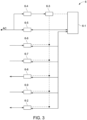
- Fig. 3 illustrates a further possible exemplary implementation of an emergency unit 6 according to the second aspect of the present invention.
- the emergency unit 6 can comprise different interfaces.
- the emergency unit 6 comprises a system-on-chip (SoC) primary controller 6-1 which may communicate with a secondary microcontroller 6-2 for higher loads.
- the emergency unit 6 comprises a buffer storage unit 6-3 adapted to supply the controllers 6-1, 6-2 and other entities of the emergency unit 6 with electrical power (dashed lines) in an emergency operation mode of the photovoltaic system 1.
- SoC system-on-chip
- the emergency unit 6 comprises an interface to the AC power lines 5 to receive AC power which may be converted by a power supply transformation entity 6-4 to provide DC power for recharging the local buffer storage unit 6-3. Further, the PLC transceiver 6-5 can be connected to the AC lines 5 as illustrated in Fig. 3 . In a possible implementation, the emergency unit 6 further comprises an interface to the smart meter 8. In the illustrated embodiment, the emergency unit 6 comprises a data interface for a local area network 6-6 and for an RS485 data cable 6-7. Further possible interfaces can be CAN, RS232, EE-Bus, Modbus, KNX Bus, TCP/IP, Modbus TCP, etc.
- the emergency unit 6 further comprises an interface with the emergency switch 7.
- the emergency unit 6 comprises a solid state relay SSR 6-8 to output a switch-on/switch-off control signal CTRL 1 for switching the emergency switch 7 between an on-switching state and an off-switching state.
- the emergency unit 6 can comprise in a possible implementation a feedback interface 6-9 receiving a feedback about the switching state of the emergency switch 7.
- the secondary controller 6-2 can be connected to external entities or devices such as a heat pump or external relays (GPIOs).
- the primary controller 6-1 which may be formed by a system-on-chip can comprise a local data memory.
- the primary controller 6-1 and the secondary controller 6-2 of the emergency unit 6 are both integrated in a control unit of the emergency unit 6.
- the communication between the controllers by means of PLC can comprise different levels of priority.
- a higher communication priority level includes the communication between the inverter unit 2 and the emergency unit 6 providing the emergency operation mode functionality of the photovoltaic system 1.
- communication between the emergency unit 6 and the smart meter 8, in particular the transmission of the smart meter data smd can comprise a high priority.
- the buffer battery 6-3 may comprise a high priority PLC communication in a backup mode. Communication concerning energy management via the I/O or RS485 has in a possible implementation a lower priority.
- the AC lines 5 illustrated in Fig. 1 comprise one or more power supply lines L.
- the AC lines 5 comprise three power supply lines for the different phases L1, L2, L3 as well as a P- and N-conductor.
Landscapes
- Engineering & Computer Science (AREA)
- Power Engineering (AREA)
- Supply And Distribution Of Alternating Current (AREA)
- Photovoltaic Devices (AREA)
- Ship Loading And Unloading (AREA)
- Cultivation Of Seaweed (AREA)
Claims (15)
- Système photovoltaïque (1), comprenant :- une unité onduleur (2) conçue pour convertir une puissance électrique en courant continu (CC) générée par des modules photovoltaïques (3) en une puissance électrique en courant alternatif (CA), l'unité onduleur (2) comportant un contrôleur ;- un compteur intelligent (8) pour fournir une puissance en courant alternatif (CA) à un réseau d'alimentation électrique (11) ; et- une unité de secours (6) reliée à un onduleur par l'intermédiaire de lignes CA (5) et au compteur intelligent (8) par l'intermédiaire d'un interrupteur d'urgence (7), l'unité de secours (6) comportant un contrôleur (6A) conçu pour :ouvrir l'interrupteur d'urgence (7) pour déconnecter automatiquement le système photovoltaïque (1) du réseau d'alimentation électrique (11) si une panne du réseau d'alimentation électrique est détectée, etnotifier un état de commutation actuel de l'interrupteur d'urgence (7) au moyen d'une communication par courant porteur en ligne (CPL) par l'intermédiaire des lignes CA (5) au contrôleur de l'unité onduleur (2),dans lequel dans un mode de fonctionnement normal du système photovoltaïque (1), l'interrupteur d'urgence (7) est dans un état fermé,dans lequel, dans un mode de fonctionnement de secours du système photovoltaïque (1), l'interrupteur d'urgence (7) est dans un état ouvert pour déconnecter le système photovoltaïque (1) du réseau d'alimentation électrique (11), etdans lequel le contrôleur de l'unité onduleur (2) est conçu pour démarrer le mode de fonctionnement de secours en réponse à une notification d'état de commutation ouvert reçue à partir du contrôleur (6A) de l'unité de secours (6) .
- Système photovoltaïque selon la revendication 1, dans lequel une panne du réseau d'alimentation électrique (11) est détectée par le contrôleur (6A) de l'unité de secours (6) et/ou par le contrôleur de l'unité onduleur (2) sur la base de données de compteur intelligent (smd) fournies par le compteur intelligent (8) du système photovoltaïque (1) par l'intermédiaire d'une communication CPL.
- Système photovoltaïque selon la revendication 1 ou 2, dans lequel un réseau de charges (9) du système photovoltaïque (1) est connecté aux lignes CA (5) du système photovoltaïque (1),dans lequel, dans un mode de fonctionnement normal du système photovoltaïque (1), les charges électriques du réseau de charges (9) sont alimentées en puissance CA par le réseau d'alimentation électrique (11) par l'intermédiaire de l'interrupteur d'urgence fermé (7),dans lequel, dans un mode de fonctionnement de secours du système photovoltaïque (1) déconnecté du réseau d'alimentation électrique (11) par l'interrupteur d'urgence ouvert (7), les charges électriques du réseau de charges (9) sont alimentées en puissance CA par l'unité onduleur (2) du système photovoltaïque (1).
- Système photovoltaïque selon la revendication 1, dans lequel l'unité de secours (6) comprend un émetteur-récepteur CPL conçu pour communiquer avec un émetteur-récepteur CPL de l'unité onduleur (2) par l'intermédiaire des lignes CA (5) du système photovoltaïque (1).
- Système photovoltaïque selon l'une quelconque des revendications précédentes, dans lequel l'unité onduleur (2) est connectée à une unité de stockage (4) du système photovoltaïque (1).
- Système photovoltaïque selon l'une quelconque des revendications précédentes, dans lequel, dans le mode de fonctionnement de secours du système photovoltaïque (1), le contrôleur (6A) et l'émetteur-récepteur CPL de l'unité onduleur (2) sont alimentés en puissance électrique CC par les modules photovoltaïques (3) et/ou par l'unité de stockage (4) du système photovoltaïque (1).
- Système photovoltaïque selon l'une quelconque des revendications précédentes, dans lequel l'unité de secours (6) comprend une unité de stockage tampon conçue pour alimenter le contrôleur (6A) et l'émetteur-récepteur CPL de l'unité de secours (6) avec une puissance électrique CC dans le mode de fonctionnement de secours du système photovoltaïque (1).
- Système photovoltaïque selon l'une quelconque des revendications 2 à 6, dans lequel, si les données de compteur intelligent (smd) indiquent la fin de la panne du réseau d'alimentation électrique, le contrôleur (6A) de l'unité de secours (6) est conçu pour fermer l'interrupteur d'urgence (7) pour reconnecter automatiquement le système photovoltaïque (1) au réseau d'alimentation électrique (11) .
- Système photovoltaïque selon la revendication 8, dans lequel, si les données de compteur intelligent (smd) indiquent la fin de la panne du réseau d'alimentation électrique, le contrôleur de l'unité onduleur (2) est conçu pour informer le contrôleur (6A) de l'unité de secours (6) de continuer à maintenir l'interrupteur d'urgence (7) à l'état ouvert pendant une durée prédéfinie, et dans lequel le contrôleur (6A) de l'unité de secours (6) est conçu pour commuter l'interrupteur d'urgence (7) sur l'état fermé à la fin du temps prédéfini.
- Système photovoltaïque selon l'une quelconque des revendications précédentes, dans lequel le contrôleur de l'unité onduleur (2) est conçu pour arrêter le mode de fonctionnement d'urgence en réponse à une notification d'état de commutation fermé de l'interrupteur d'urgence (7) reçue à partir de l'unité de secours (6).
- Système photovoltaïque selon l'une quelconque des revendications précédentes, dans lequel l'unité de secours (6) et l'unité onduleur (2) comprennent des adresses de réseau local utilisées pour établir une communication CPL bidirectionnelle entre l'unité de secours (6) et l'unité onduleur (2) par l'intermédiaire des lignes CA (5) du système photovoltaïque (1).
- Système photovoltaïque selon l'une quelconque des revendications précédentes, dans lequel le compteur intelligent (8) est intégré dans l'unité de secours (6) ou est connecté par l'intermédiaire d'un câble de données à une interface de données de l'unité de secours (6).
- Système photovoltaïque selon l'une quelconque des revendications précédentes, dans lequel le contrôleur (6A) de l'unité de secours (6) et/ou le contrôleur de l'unité onduleur (2) sont conçus pour effectuer une gestion énergétique de la puissance électrique CA consommée par les charges du réseau de charges (9), la puissance CC générée par les modules photovoltaïques (3), et la puissance CC stockée dans l'unité de stockage (4) du système photovoltaïque (1).
- Système photovoltaïque selon l'une quelconque des revendications 2 à 13, dans lequel les données de compteur intelligent (smd) fournies par le compteur intelligent (8) comprennent une tension, un courant électrique et/ou une fréquence pour toutes les phases de courant, L, du réseau d'alimentation électrique (11).
- Unité de secours pour un système photovoltaïque (1) selon l'une quelconque des revendications précédentes, ladite unité de secours (6) comprenant :- un contrôleur (6A) conçu pour commander un interrupteur d'urgence (7) pour connecter le système photovoltaïque (1) dans un mode de fonctionnement normal au réseau d'alimentation électrique (11) et pour déconnecter le système photovoltaïque (1) dans un mode de fonctionnement de secours du réseau d'alimentation électrique (11) ; et- un émetteur-récepteur CPL (6B) conçu pour établir une communication CPL avec un contrôleur d'une unité onduleur (2) du système photovoltaïque (1) par l'intermédiaire de lignes CA (5) du système photovoltaïque (1).
Applications Claiming Priority (2)
| Application Number | Priority Date | Filing Date | Title |
|---|---|---|---|
| EP20200133.5A EP3979450A1 (fr) | 2020-10-05 | 2020-10-05 | Système photovoltaïque |
| PCT/EP2021/076656 WO2022073804A1 (fr) | 2020-10-05 | 2021-09-28 | Système photovoltaïque |
Publications (3)
| Publication Number | Publication Date |
|---|---|
| EP4226474A1 EP4226474A1 (fr) | 2023-08-16 |
| EP4226474B1 true EP4226474B1 (fr) | 2024-11-06 |
| EP4226474C0 EP4226474C0 (fr) | 2024-11-06 |
Family
ID=72752374
Family Applications (2)
| Application Number | Title | Priority Date | Filing Date |
|---|---|---|---|
| EP20200133.5A Withdrawn EP3979450A1 (fr) | 2020-10-05 | 2020-10-05 | Système photovoltaïque |
| EP21786141.8A Active EP4226474B1 (fr) | 2020-10-05 | 2021-09-28 | Système photovoltaïque |
Family Applications Before (1)
| Application Number | Title | Priority Date | Filing Date |
|---|---|---|---|
| EP20200133.5A Withdrawn EP3979450A1 (fr) | 2020-10-05 | 2020-10-05 | Système photovoltaïque |
Country Status (9)
| Country | Link |
|---|---|
| US (1) | US12463460B2 (fr) |
| EP (2) | EP3979450A1 (fr) |
| CN (1) | CN116325409A (fr) |
| AU (1) | AU2021358305B2 (fr) |
| ES (1) | ES2994681T3 (fr) |
| HU (1) | HUE069589T2 (fr) |
| IL (1) | IL301931A (fr) |
| PL (1) | PL4226474T3 (fr) |
| WO (1) | WO2022073804A1 (fr) |
Family Cites Families (7)
| Publication number | Priority date | Publication date | Assignee | Title |
|---|---|---|---|---|
| WO2015111410A1 (fr) * | 2014-01-22 | 2015-07-30 | 京セラ株式会社 | Système de régulation de l'énergie et procédé permettant de commander un système de régulation de l'énergie |
| CN203689677U (zh) * | 2014-02-14 | 2014-07-02 | 瑞斯康微电子(深圳)有限公司 | 一种光伏逆变器电力载波通信系统 |
| WO2016123305A1 (fr) * | 2015-01-28 | 2016-08-04 | Abb Technology Ag | Arrêt d'un agencement de panneaux d'énergie |
| US10965153B2 (en) * | 2016-02-05 | 2021-03-30 | Duke Energy Corporation | Methods of microgrid communications and connection transitions |
| EP3439133B1 (fr) * | 2016-05-18 | 2020-12-09 | Murata Manufacturing Co., Ltd. | Dispositif d'alimentation électrique, procédé d'alimentation électrique et dispositif de stockage d'énergie |
| CN109638795B (zh) * | 2019-01-16 | 2020-07-24 | 科华恒盛股份有限公司 | 组串式光伏逆变系统急停控制方法及装置 |
| CN110661295B (zh) * | 2019-10-15 | 2022-07-15 | 阳光新能源开发股份有限公司 | 逆变器和光伏发电系统 |
-
2020
- 2020-10-05 EP EP20200133.5A patent/EP3979450A1/fr not_active Withdrawn
-
2021
- 2021-09-28 ES ES21786141T patent/ES2994681T3/es active Active
- 2021-09-28 WO PCT/EP2021/076656 patent/WO2022073804A1/fr not_active Ceased
- 2021-09-28 CN CN202180068349.7A patent/CN116325409A/zh active Pending
- 2021-09-28 HU HUE21786141A patent/HUE069589T2/hu unknown
- 2021-09-28 IL IL301931A patent/IL301931A/en unknown
- 2021-09-28 PL PL21786141.8T patent/PL4226474T3/pl unknown
- 2021-09-28 AU AU2021358305A patent/AU2021358305B2/en active Active
- 2021-09-28 EP EP21786141.8A patent/EP4226474B1/fr active Active
- 2021-09-28 US US18/246,615 patent/US12463460B2/en active Active
Also Published As
| Publication number | Publication date |
|---|---|
| HUE069589T2 (hu) | 2025-03-28 |
| US12463460B2 (en) | 2025-11-04 |
| EP4226474A1 (fr) | 2023-08-16 |
| EP4226474C0 (fr) | 2024-11-06 |
| US20250183710A1 (en) | 2025-06-05 |
| CN116325409A (zh) | 2023-06-23 |
| IL301931A (en) | 2023-06-01 |
| EP3979450A1 (fr) | 2022-04-06 |
| AU2021358305B2 (en) | 2023-12-14 |
| PL4226474T3 (pl) | 2025-03-17 |
| AU2021358305A1 (en) | 2023-03-23 |
| ES2994681T3 (en) | 2025-01-29 |
| WO2022073804A1 (fr) | 2022-04-14 |
Similar Documents
| Publication | Publication Date | Title |
|---|---|---|
| US12431702B2 (en) | Integrated electrical management system and architecture | |
| EP2702656B1 (fr) | Gestion de la demande en énergie électrique pour un réseau à basse tension avec une pluralité de socles intelligents | |
| AU2012212484A1 (en) | Energy interface system | |
| US12395009B2 (en) | Convertible energy control system | |
| WO2021108545A1 (fr) | Procédés et appareils de commande de connectivité de réseaux | |
| US12463460B2 (en) | Photovoltaic system | |
| AU2021301379B2 (en) | Method and apparatus for balancing loads on split-phase islanded systems | |
| US20250125627A1 (en) | Energy management systems | |
| CN210806749U (zh) | 一种用于储能系统的并离网切换电路 | |
| CN114435180B (zh) | 能量供应系统、用于操作能量供应系统的方法及车辆 | |
| TWI622248B (zh) | 可自動切換電源的電源分配單元 | |
| JP2018064430A (ja) | 充放電装置及び電力制御装置 | |
| CN215267684U (zh) | 一种蓄电池核容放电装置 | |
| WO2025014631A1 (fr) | Dérivation basse tension pour une tenue aux tensions ca extrêmement basses | |
| WO2023129422A1 (fr) | Micro-onduleur destiné à être utilisé avec un système de stockage | |
| WO2025259416A1 (fr) | Colliers compteurs conçus pour être utilisés avec des systèmes de gestion d'énergie | |
| AU2024355341A1 (en) | Bi-directional vehicle charging apparatus and method | |
| KR20230090900A (ko) | 전력 변환 장치에 사용되는 입출력 컴포넌트 시스템 | |
| CN121586979A (zh) | 储能系统和操作该储能系统的方法 |
Legal Events
| Date | Code | Title | Description |
|---|---|---|---|
| STAA | Information on the status of an ep patent application or granted ep patent |
Free format text: STATUS: UNKNOWN |
|
| STAA | Information on the status of an ep patent application or granted ep patent |
Free format text: STATUS: THE INTERNATIONAL PUBLICATION HAS BEEN MADE |
|
| PUAI | Public reference made under article 153(3) epc to a published international application that has entered the european phase |
Free format text: ORIGINAL CODE: 0009012 |
|
| STAA | Information on the status of an ep patent application or granted ep patent |
Free format text: STATUS: REQUEST FOR EXAMINATION WAS MADE |
|
| 17P | Request for examination filed |
Effective date: 20230505 |
|
| AK | Designated contracting states |
Kind code of ref document: A1 Designated state(s): AL AT BE BG CH CY CZ DE DK EE ES FI FR GB GR HR HU IE IS IT LI LT LU LV MC MK MT NL NO PL PT RO RS SE SI SK SM TR |
|
| DAV | Request for validation of the european patent (deleted) | ||
| DAX | Request for extension of the european patent (deleted) | ||
| GRAP | Despatch of communication of intention to grant a patent |
Free format text: ORIGINAL CODE: EPIDOSNIGR1 |
|
| STAA | Information on the status of an ep patent application or granted ep patent |
Free format text: STATUS: GRANT OF PATENT IS INTENDED |
|
| INTG | Intention to grant announced |
Effective date: 20240619 |
|
| GRAS | Grant fee paid |
Free format text: ORIGINAL CODE: EPIDOSNIGR3 |
|
| GRAA | (expected) grant |
Free format text: ORIGINAL CODE: 0009210 |
|
| STAA | Information on the status of an ep patent application or granted ep patent |
Free format text: STATUS: THE PATENT HAS BEEN GRANTED |
|
| AK | Designated contracting states |
Kind code of ref document: B1 Designated state(s): AL AT BE BG CH CY CZ DE DK EE ES FI FR GB GR HR HU IE IS IT LI LT LU LV MC MK MT NL NO PL PT RO RS SE SI SK SM TR |
|
| REG | Reference to a national code |
Ref country code: GB Ref legal event code: FG4D |
|
| REG | Reference to a national code |
Ref country code: CH Ref legal event code: EP |
|
| REG | Reference to a national code |
Ref country code: DE Ref legal event code: R096 Ref document number: 602021021515 Country of ref document: DE |
|
| REG | Reference to a national code |
Ref country code: IE Ref legal event code: FG4D |
|
| U01 | Request for unitary effect filed |
Effective date: 20241111 |
|
| U07 | Unitary effect registered |
Designated state(s): AT BE BG DE DK EE FI FR IT LT LU LV MT NL PT RO SE SI Effective date: 20241119 |
|
| REG | Reference to a national code |
Ref country code: ES Ref legal event code: FG2A Ref document number: 2994681 Country of ref document: ES Kind code of ref document: T3 Effective date: 20250129 |
|
| REG | Reference to a national code |
Ref country code: HU Ref legal event code: AG4A Ref document number: E069589 Country of ref document: HU |
|
| PG25 | Lapsed in a contracting state [announced via postgrant information from national office to epo] |
Ref country code: HR Free format text: LAPSE BECAUSE OF FAILURE TO SUBMIT A TRANSLATION OF THE DESCRIPTION OR TO PAY THE FEE WITHIN THE PRESCRIBED TIME-LIMIT Effective date: 20241106 Ref country code: IS Free format text: LAPSE BECAUSE OF FAILURE TO SUBMIT A TRANSLATION OF THE DESCRIPTION OR TO PAY THE FEE WITHIN THE PRESCRIBED TIME-LIMIT Effective date: 20250306 |
|
| PG25 | Lapsed in a contracting state [announced via postgrant information from national office to epo] |
Ref country code: NO Free format text: LAPSE BECAUSE OF FAILURE TO SUBMIT A TRANSLATION OF THE DESCRIPTION OR TO PAY THE FEE WITHIN THE PRESCRIBED TIME-LIMIT Effective date: 20250206 |
|
| PG25 | Lapsed in a contracting state [announced via postgrant information from national office to epo] |
Ref country code: GR Free format text: LAPSE BECAUSE OF FAILURE TO SUBMIT A TRANSLATION OF THE DESCRIPTION OR TO PAY THE FEE WITHIN THE PRESCRIBED TIME-LIMIT Effective date: 20250207 |
|
| PG25 | Lapsed in a contracting state [announced via postgrant information from national office to epo] |
Ref country code: RS Free format text: LAPSE BECAUSE OF FAILURE TO SUBMIT A TRANSLATION OF THE DESCRIPTION OR TO PAY THE FEE WITHIN THE PRESCRIBED TIME-LIMIT Effective date: 20250206 |
|
| PG25 | Lapsed in a contracting state [announced via postgrant information from national office to epo] |
Ref country code: SM Free format text: LAPSE BECAUSE OF FAILURE TO SUBMIT A TRANSLATION OF THE DESCRIPTION OR TO PAY THE FEE WITHIN THE PRESCRIBED TIME-LIMIT Effective date: 20241106 |
|
| PG25 | Lapsed in a contracting state [announced via postgrant information from national office to epo] |
Ref country code: SK Free format text: LAPSE BECAUSE OF FAILURE TO SUBMIT A TRANSLATION OF THE DESCRIPTION OR TO PAY THE FEE WITHIN THE PRESCRIBED TIME-LIMIT Effective date: 20241106 |
|
| PG25 | Lapsed in a contracting state [announced via postgrant information from national office to epo] |
Ref country code: CZ Free format text: LAPSE BECAUSE OF FAILURE TO SUBMIT A TRANSLATION OF THE DESCRIPTION OR TO PAY THE FEE WITHIN THE PRESCRIBED TIME-LIMIT Effective date: 20241106 |
|
| PLBE | No opposition filed within time limit |
Free format text: ORIGINAL CODE: 0009261 |
|
| STAA | Information on the status of an ep patent application or granted ep patent |
Free format text: STATUS: NO OPPOSITION FILED WITHIN TIME LIMIT |
|
| 26N | No opposition filed |
Effective date: 20250807 |
|
| PGFP | Annual fee paid to national office [announced via postgrant information from national office to epo] |
Ref country code: HU Payment date: 20250926 Year of fee payment: 5 |
|
| U20 | Renewal fee for the european patent with unitary effect paid |
Year of fee payment: 5 Effective date: 20250925 |
|
| PGFP | Annual fee paid to national office [announced via postgrant information from national office to epo] |
Ref country code: PL Payment date: 20250922 Year of fee payment: 5 |
|
| PGFP | Annual fee paid to national office [announced via postgrant information from national office to epo] |
Ref country code: ES Payment date: 20251008 Year of fee payment: 5 |
|
| REG | Reference to a national code |
Ref country code: CH Ref legal event code: H13 Free format text: ST27 STATUS EVENT CODE: U-0-0-H10-H13 (AS PROVIDED BY THE NATIONAL OFFICE) Effective date: 20260504 |