EP4226875B1 - Dispositif à ondes de choc doté d'une source à alignement automatique avec un dispositif à rayons x - Google Patents
Dispositif à ondes de choc doté d'une source à alignement automatique avec un dispositif à rayons x Download PDFInfo
- Publication number
- EP4226875B1 EP4226875B1 EP22155808.3A EP22155808A EP4226875B1 EP 4226875 B1 EP4226875 B1 EP 4226875B1 EP 22155808 A EP22155808 A EP 22155808A EP 4226875 B1 EP4226875 B1 EP 4226875B1
- Authority
- EP
- European Patent Office
- Prior art keywords
- ultrasound
- ray
- axis
- shockwave source
- shock wave
- Prior art date
- Legal status (The legal status is an assumption and is not a legal conclusion. Google has not performed a legal analysis and makes no representation as to the accuracy of the status listed.)
- Active
Links
Images


Classifications
-
- A—HUMAN NECESSITIES
- A61—MEDICAL OR VETERINARY SCIENCE; HYGIENE
- A61B—DIAGNOSIS; SURGERY; IDENTIFICATION
- A61B17/00—Surgical instruments, devices or methods
- A61B17/22—Implements for squeezing-off ulcers or the like on inner organs of the body; Implements for scraping-out cavities of body organs, e.g. bones; for invasive removal or destruction of calculus using mechanical vibrations; for removing obstructions in blood vessels, not otherwise provided for
- A61B17/225—Implements for squeezing-off ulcers or the like on inner organs of the body; Implements for scraping-out cavities of body organs, e.g. bones; for invasive removal or destruction of calculus using mechanical vibrations; for removing obstructions in blood vessels, not otherwise provided for for extracorporeal shock wave lithotripsy [ESWL], e.g. by using ultrasonic waves
- A61B17/2255—Means for positioning patient, shock wave apparatus or locating means, e.g. mechanical aspects, patient beds, support arms or aiming means
-
- A—HUMAN NECESSITIES
- A61—MEDICAL OR VETERINARY SCIENCE; HYGIENE
- A61B—DIAGNOSIS; SURGERY; IDENTIFICATION
- A61B17/00—Surgical instruments, devices or methods
- A61B17/22—Implements for squeezing-off ulcers or the like on inner organs of the body; Implements for scraping-out cavities of body organs, e.g. bones; for invasive removal or destruction of calculus using mechanical vibrations; for removing obstructions in blood vessels, not otherwise provided for
- A61B17/225—Implements for squeezing-off ulcers or the like on inner organs of the body; Implements for scraping-out cavities of body organs, e.g. bones; for invasive removal or destruction of calculus using mechanical vibrations; for removing obstructions in blood vessels, not otherwise provided for for extracorporeal shock wave lithotripsy [ESWL], e.g. by using ultrasonic waves
- A61B17/2256—Implements for squeezing-off ulcers or the like on inner organs of the body; Implements for scraping-out cavities of body organs, e.g. bones; for invasive removal or destruction of calculus using mechanical vibrations; for removing obstructions in blood vessels, not otherwise provided for for extracorporeal shock wave lithotripsy [ESWL], e.g. by using ultrasonic waves with means for locating or checking the concrement, e.g. X-ray apparatus, imaging means
- A61B17/2258—Implements for squeezing-off ulcers or the like on inner organs of the body; Implements for scraping-out cavities of body organs, e.g. bones; for invasive removal or destruction of calculus using mechanical vibrations; for removing obstructions in blood vessels, not otherwise provided for for extracorporeal shock wave lithotripsy [ESWL], e.g. by using ultrasonic waves with means for locating or checking the concrement, e.g. X-ray apparatus, imaging means integrated in a central portion of the shock wave apparatus
-
- A—HUMAN NECESSITIES
- A61—MEDICAL OR VETERINARY SCIENCE; HYGIENE
- A61B—DIAGNOSIS; SURGERY; IDENTIFICATION
- A61B17/00—Surgical instruments, devices or methods
- A61B2017/00017—Electrical control of surgical instruments
-
- A—HUMAN NECESSITIES
- A61—MEDICAL OR VETERINARY SCIENCE; HYGIENE
- A61B—DIAGNOSIS; SURGERY; IDENTIFICATION
- A61B17/00—Surgical instruments, devices or methods
- A61B2017/00017—Electrical control of surgical instruments
- A61B2017/00022—Sensing or detecting at the treatment site
-
- A—HUMAN NECESSITIES
- A61—MEDICAL OR VETERINARY SCIENCE; HYGIENE
- A61B—DIAGNOSIS; SURGERY; IDENTIFICATION
- A61B17/00—Surgical instruments, devices or methods
- A61B2017/00017—Electrical control of surgical instruments
- A61B2017/00022—Sensing or detecting at the treatment site
- A61B2017/00075—Motion
-
- A—HUMAN NECESSITIES
- A61—MEDICAL OR VETERINARY SCIENCE; HYGIENE
- A61B—DIAGNOSIS; SURGERY; IDENTIFICATION
- A61B17/00—Surgical instruments, devices or methods
- A61B2017/00681—Aspects not otherwise provided for
- A61B2017/00694—Aspects not otherwise provided for with means correcting for movement of or for synchronisation with the body
- A61B2017/00699—Aspects not otherwise provided for with means correcting for movement of or for synchronisation with the body correcting for movement caused by respiration, e.g. by triggering
-
- A—HUMAN NECESSITIES
- A61—MEDICAL OR VETERINARY SCIENCE; HYGIENE
- A61B—DIAGNOSIS; SURGERY; IDENTIFICATION
- A61B17/00—Surgical instruments, devices or methods
- A61B2017/00681—Aspects not otherwise provided for
- A61B2017/00725—Calibration or performance testing
Definitions
- the invention relates to an extracorporeal shock wave or ultrasound therapy system, e.g., a lithotripsy system or Lithotripter for non-invasive treatment of stones, like e.g., kidney stones, urinary stones, gallstones, or other calculi within a mammal's body using acoustic pulses, or other applications of an extracorporeal shock wave or ultrasound therapy system.
- an extracorporeal shock wave or ultrasound therapy system e.g., a lithotripsy system or Lithotripter for non-invasive treatment of stones, like e.g., kidney stones, urinary stones, gallstones, or other calculi within a mammal's body using acoustic pulses, or other applications of an extracorporeal shock wave or ultrasound therapy system.
- X-ray images are taken from a patient. These images are used for locating a stone and for aligning a therapy source like a shock wave or ultrasound therapy source.
- Such an X-ray image shows a projection into a plane orthogonal to the X-ray beam, herein referred ax X-Y plane.
- An information about the height, herein the Z-axis is not available.
- the lithotripsy system is calibrated such that the focal area of the therapy source is at the rotation axis. This is done by taking at least two X-ray images under different angles alpha1 and alpha2 and comparing the positions of an object, e.g., stone or calibration object in the X-ray images. If the position differs, the object is not at the rotation axis. Normally, the X-ray system is moved to bring the object into the rotation axis.
- EP 150 674 1 A1 discloses a lithotripsy system where the X-ray system can be mechanically coupled to the shockwave source for alignment.
- the axis of the x-ray system should be parallel to the axis of the shockwave source, further the focal area of the shockwave source should be on the axis of the x-ray system. This allows for proper triangulation and targeting.
- Mechanically coupling is a straightforward approach which requires a complex mechanical system and prevents separating the X-ray device from the shockwave device.
- EP 2 628 456 A1 discloses a shock wave therapy device with dynamic target tracking.
- US 2010/080349 A1 discloses a breast biopsy device.
- EP 3 875 048 A1 discloses a shockwave therapy system with 3D control.
- US 2019/0350685 A1 discloses an electromagnetic navigation system.
- the problem to be solved by the invention is to provide an ultrasound and/or shock wave device, including an ultrasound and/or shockwave source and an X-ray system wherein the ultrasound and/or shockwave source is automatically aligned with the X-ray system without mechanically coupling between the ultra-sound and/or shockwave source without mechanically coupling.
- the ultrasound and/or shock wave device should be comparatively robust and simple to use. Solutions of the problem according to the invention are defined in the independent claims. The dependent claims relate to further improvements of the invention.
- a shock wave and/or ultrasound device which may be a lithotripter includes an ultrasound and/or shockwave source together with an X-ray system including an X-ray source and a detector. It may further include a patient table.
- the ultrasound and/or shockwave source is suspended on a hexapod, such that it can be displaced in three degrees of freedom and tilted or rotated about two or three degrees of freedom. Therefore, no complex X-ray system mechanism and complex X-ray adjustment procedures are required.
- the X-ray system may only be aligned coarsely.
- the treatment source may then be adjusted by the hexapod drive such that the axes of the X-ray system and the treatment source are the same. As the hexapod allows a free orientation of the source in space, it can basically adjust the treatment source to any orientation of the X-ray source.
- a y-axis may be a longitudinal axis through the center of the table.
- An x-axis may be orthogonal to the y-axis and in the plane of the table surface.
- a z-axis is orthogonal to the plane of the table surface and therefore orthogonal to the x-axis and the y-axis and in a direction upward from the table.
- There may also be a first rotation around the x-axis, a second rotation and a third rotation around the z-axis.
- a positive rotation may be a clockwise rotation in a direction of a positive axis.
- the orientation of the ultrasound and/or shockwave source is defined by an axis extending from the center of the source to the center of the focal area.
- the orientation of the X-ray system is defined by an axis at the path of the X-ray beam between the X-ray source and the detector.
- the shock wave or ultrasound therapy system may include a system controller which may control at least the X-ray system and the hexapod drive of the ultra-sound and/or shockwave source.
- the system controller may control the X-ray system for taking at least one X-ray image which may show a known object, which may be a calibration object or at least a part of the ultrasound and/or shockwave source.
- the known object may be a calibration phantom or focal phantom and may include a first X-ray absorbing object and a second X-ray absorbing object arranged distant from each other symmetrically to or at the axis of the ultrasound and/or shockwave source. Both X-ray absorbing objects may have different sizes and a symmetrical structure. They may be rings of different diameters.
- the known object may also be part of the structure of the shock wave and/or ultrasound therapy system, which is visible in an X-ray image.
- the system controller may be configured to control the X-ray system to take a first image showing a first X-ray absorbing object and a second X-ray absorbing object.
- the system controller may be configured to process the first image, to detect the first and second X-ray absorbing objects and to estimate the displacement of axes between a center axis of the ultra-sound and/or shockwave source and a center axis of the X-ray system. This may be done based on calculating the centers of and/or the distance between the X-ray absorbing objects.
- the system controller may further be configured to control the hexapod drive for moving of the ultrasound and/or shockwave source to compensate for the displacement of axes.
- the system controller may further be configured to control the X-ray system to take a second image showing a first X-ray absorbing object and a second X-ray absorbing object.
- the system controller may be configured to process the second image, to detect the first and second X-ray absorbing objects and to estimate the displacement of axes between a center axis of the ultra-sound and/or shockwave source and a center axis of the X-ray system.
- the system controller may further be configured to control the hexapod drive for further adjustment if the displacement of axes is above a limit value. This may be repeated until the displacement of axes is below or equal to the limit value or a maximum count of iterations have been reached.
- the system controller may be configured to take at least a further image after changing alignment of the ultrasound and/or shockwave source to verify the alignment. It may further be configured to repeat the steps above until an alignment within predetermined limits is reached or an operator is satisfied, or a maximum number of cycles is reached.
- the ultrasound and/or shockwave source may be of any type suitable for generating shock waves. It may include a shock wave generator and/or transducer, which may include at least one of a coil, a spark gap or a Piezo transducer.
- the shock wave generator/transducer may be partially enclosed by a reflector. Depending on the type of transducer, the reflector may have a parabolic or half-elliptic shape. In case of a piezo transducer, the transducer may itself have a spherical shape, such that a reflector may not be needed.
- the ultrasound and/or shockwave source may have a focal volume which is distant from the ultrasound and/or shockwave source and normally around a center axis of the ultrasound and/or shockwave source.
- the focal volume may be defined as a volume, where the maximum shock wave intensity is maintained with a deviation of maximal -3 dB or -6 dB. If the focal volume is defined with a 6 dB deviation, the pressure at the limit of the zone is half of the maximum pressure inside the zone.
- the focal volume may have an elliptical shape with a length in an axial direction (defined by the center axis) of the ultrasound and/or shockwave source axis of 10 to 15 cm and a diameter between 5 and 15 mm. The focal volume normally is spaced from the shock wave generator and/or transducer.
- the hexapod drive bearing the ultrasound and/or shockwave source is also known as a hexapod platform.
- a hexapod platform also is called a Stewart platform.
- it is a type of parallel manipulator or parallel robot that has six linear actuators, which may be hydraulic or pneumatic jacks or electric linear actuators. Examples of electric linear actors are motors coupled to a belt or a spindle to perform a linear movement.
- These linear actuators are connected in pairs to three mounting positions at a base, crossing over to three mounting positions at the ultrasound and/or shockwave source.
- Each connection of a linear actuator to either the base or the ultrasound and/or shockwave source may include a universal joint, also called a cardan joint or a ball joint.
- the ultrasound and/or shockwave source can be moved in six degrees of freedom with respect to the base. There are three degrees of translation and three degrees of rotation. Although the use of six linear actuators is preferred, a lower number of actuators may be used, e.g., like in a delta robot with three actuators.
- the hexapod drive allows to adjust the position of an ultrasound and/or shockwave source relative to a patient's body and/or the X-ray system. Positioning of the ultrasound and/or shockwave source may be done automatically or by manual control. An automatic control may allow quick adjustment and it may also allow to store and retrieve preconfigured settings.
- Such a hexapod drive is a very robust and mechanical stiff support or suspension of the ultrasound and/or shockwave source. Therefore, it can withstand high forces from the patient body, the weight of the ultrasound and/or shockwave source and dynamic loads which occur when shockwave pulses are generated. Further, a hexapod drive can be moved quickly. Therefore, a stable positioning of the ultrasound and/or shockwave source is achieved providing the additional ability to quickly correct deviations and movements by the patient.
- a hexapod drive may allow movement in all 6 degrees of freedom. This allows for a precise adjustment of the position of the focal volume of the ultrasound and/or shockwave source and/or the path of the ultrasound and/or shockwave though the body of the patient.
- the patient table may have a basically planar surface defining a longitudinal axis. It is configured for accommodating a patient.
- the ultrasound and/or shockwave source may be mounted below the patient table.
- a shockwave source may be mounted in alternative ways, e.g., on a stand or support.
- the base may be standing on a floor directly or by a stand or it may be attached to a floor.
- the base may also hold the table.
- a method of aligning an ultrasound and/or shockwave source with an X-ray system includes the steps of:
- the steps c), d) and e) may be repeated multiple times until the displacement of axes is below a limit value.
- the X-ray system, the ultrasound and/or shockwave source are oriented in a cartesian coordinate system as defined above.
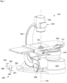
- FIG. 1 a first embodiment of a lithotripsy system, known from EP 3 875 048 A1 , is shown.
- the invention works with any ultrasound and/or shockwave treatment system.
- An extra-corporeal ultrasound and/or shockwave lithotripsy system for non-invasive treatment of stones 100 comprises a patient table 110, an ultra-sound and/or shockwave source 120.
- the ultrasound and/or shockwave source 120 is mounted to a hexapod drive 180.
- the hexapod drive 180 may further be held by a stand 220.
- the hexapod drive 180 allows fine positioning of the ultrasound and/or shockwave source 120 in multiple axes relative to the patient table 110 and therefore relative to the patient (not shown in this figure).
- the ultrasound and/or shockwave source 120 has a focal volume which moves together with the source. In an embodiment the distance of the focal volume to the source may be modified.
- the patient table 110 is based on a stand 220 which may stand on a floor.
- the table 110 may be held by a positioning device 240 to move the table relative to the ultrasound and/or shockwave source 120 together with the hexapod drive 180.
- a movement of the patient table may be coarse positioning which may be limited to a displacement in 3 axes.
- the table 110 may have a flat surface for accommodating a patient who is not shown here.
- An X-ray device 290 acting as targeting device, may be provided. It may have an X-ray tube 296 opposing an X-ray detector 294, both mounted tiltable at a C-arm 292. There is a common center axis 150 on which the X-ray device and the ultra-sound and/or shockwave source are aligned.
- a cartesian coordinate system 280 may be used.
- a y-axis 282 which may be a longitudinal axis through the center of the table.
- an x-axis 281 orthogonal to the y-axis and in the plane of the table surface.
- a z-axis 283 is orthogonal to the plane of the table surface and therefore orthogonal to the x-axis and the y-axis.
- a positive rotation may be a clockwise rotation in a view along a positive axis.
- a hexapod drive 180 may allow movement in all these 6 degrees of freedom. This allows for a precise adjustment of the position of the focal volume of the ultra-sound and/or shockwave source 120.
- the patient table may be positioned for a slow and coarse adjustment in 3 degrees of translation for larger distances, but normally no rotation, whereas the hexapod drive provides a comparatively quick adjustment in 3 degrees of translation and 3 degrees of rotation.
- the movement distances of the table may be larger than the movement distances of the hexapod drive.
- the X-ray device may at least be tiltable to perform a second rotation 285 around an axis parallel to the y-axis 282. It may also be tiltable around an axis parallel to the Y axis. It may further be translated in a plane defined by the X and Y axis. This means, it may be moved on the floor which is also in the X-Y plane.
- a control panel 400 For control of the movement of the ultrasound and/or shockwave source 120 relative to the patient table 110, a control panel 400 may be provided.
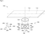
- FIG 2 shows a more schematic perspective view of an ultrasound and/or shockwave source 120 mounted to a hexapod drive 180.
- a shock wave or ultra-sound device which may be a lithotripter 100 may include a patient table 110 and an ultrasound and/or shockwave source 120.
- the ultrasound and/or shockwave source 120 may be arranged below the patient table 110, such that a patient (not shown here) may be accommodated on top of the patient table.
- the patient table may have a longitudinal axis 112. There may be a hole or cutout in the patient table at the position of the ultrasound and/or shockwave source.
- the ultrasound and/or shockwave source 120 is supported by and/or suspended on a hexapod drive 180.
- a hexapod drive 180 Basically, it is a type of parallel manipulator or parallel robot that has six linear actuators 181 - 186, which may be hydraulic or pneumatic jacks or electric linear actuators. These linear actuators are connected in pairs to three mounting positions 191, 192, 193 at a base 170, crossing over to three mounting positions 194, 195, 196 at the ultrasound and/or shockwave source 120.
- Each connection of a linear actuator to either the base or the ultra-sound and/or shockwave source may include a universal joint, also called a cardan joint or a ball joint.
- the ultrasound and/or shockwave source can be moved in six degrees of freedom with respect to the base.
- the ultrasound and/or shockwave source 120 may have a center axis 150.
- Figure 3 shows an embodiment in a side view.
- a patient 800 is positioned on top of the patient table 110.
- the patient may have a kidney 810 with a kidney stone 820.
- An X-ray system includes an X-ray tube 294 shown below the patient and an X-ray detector 294 shown above the patient, both connected and held by a C-arm 292.
- the X-ray system is aligned with the shock wave generator 130 such that both are on the axis 150.
- the X-ray system may further include a C-arm drive 293, which may be an electrical motor with a gear.
- a system controller controls at least operation of the X-ray system 290, of the C-arm by means a C-arm control 430 and of the hexapod drive 180 by means of a hexapod control 420.
- the system controller may also control the X-ray tube 296 and may receive images from the X-ray detector 294.
- the ultrasound and/or shockwave source 120 is shown in a sectional view. It may have a shock wave generator 130 which may be a coil as shown herein and which is at least partially enclosed by a reflector 129. Further, the center axis 150 is marked as a dashed line. Normally, the interior of the reflector and the space between the source and the patient is filled with a liquid like water or another shockwave conducting medium. To contain the water within the volume, a coupling cushion 125 may be provided.
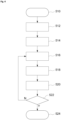
- Figure 4 shows a flow diagram of a method of aligning an ultrasound and/or shockwave source 120 with an X-ray system.
- the method utilizes a focal phantom including a first X-ray absorbing object 127 and a second X-ray absorbing object 128 arranged distant from each other at the axis of the ultrasound and/or shockwave source 120.
- the method including the steps of:
- Steps 516 to 522 may be repeated multiple times until the offset between the images may be within a predefined limit or further iterations do not reduce the offset.
- FIG. 5 shows a sketch of a focal phantom.
- An ultrasound and/or shockwave source 120 may have a first X-ray absorbing object 127 and a second X-ray absorbing object 128 distant in z-direction from each other. Both X-ray absorbing objects may be arranged symmetrical to the center axis of the source. Both X-ray absorbing objects may have different sizes and a symmetrical structure. They may be rings of different diameters. The first X-ray absorbing object 127 and a second X-ray absorbing object 128 may be removable from the ultrasound and/or shockwave source 120.
- a shock wave source having a centered cylindrical coil 122 within a reflector 129 is shown.
- the first X-ray absorbing object 127 may be at one end of the coil, where the second X-ray absorbing object 128 may be at the other side thereof.
- An X-ray beam 298 from X-ray tube 294 passes through the source 120 and produces images of the Y-ray absorbing objects at the detector.
- the axis of the ultrasound and/or shockwave source 120 may be moved by the hexapod drive 180 until the images of both X-ray absorbing objects are centered. In this case, the source 120 and the X-ray system 290 are on the same axis.
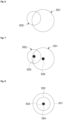
- Figures 6 to 8 show X-ray images made with the procedure steps as explained in Fig. 4 with a focal phantom of Fig. 5 .
- Fig. 6 shows an X-ray image as made in step 512. It may show an X-ray image 551 of first X-ray absorbing object 127 and an X-ray image 552 of second X-ray absorbing object 128. If the axis of the X-ray system 290 is not aligned with the axis of the ultrasound and/or shockwave source 120, the objects are not centered.
- step 514 the center 554 of X-ray image of first X-ray absorbing object and the center 553 of X-ray image of second X-ray absorbing object are determined.
- Fig. 6 shows an X-ray image as made in step 512. It may show an X-ray image 551 of first X-ray absorbing object 127 and an X-ray image 552 of second X-ray absorbing object 128. If
- step 8 shows the image taken in step 518 with calculated centers from step 520, which overlap, as in this example the axis may be aligned. If the axes are still not aligned, then the centers would not be at the same position. In this case another iteration may be made.
- Figure 9 shows an embodiment in two tilted positions.
- a shock wave and/or ultrasound therapy system is shown in vertical position.
- the same system is shown in position tilted at an angle 840 around an axis 830 at the center of stone 820.
- the tilt axis is aligned with an axis of a stone. The image would look the same if the tilt axis is aligned with an axis of a known object or a phantom.
Landscapes
- Health & Medical Sciences (AREA)
- Surgery (AREA)
- Life Sciences & Earth Sciences (AREA)
- Nuclear Medicine, Radiotherapy & Molecular Imaging (AREA)
- Heart & Thoracic Surgery (AREA)
- Vascular Medicine (AREA)
- Engineering & Computer Science (AREA)
- Biomedical Technology (AREA)
- Orthopedic Medicine & Surgery (AREA)
- Medical Informatics (AREA)
- Molecular Biology (AREA)
- Animal Behavior & Ethology (AREA)
- General Health & Medical Sciences (AREA)
- Public Health (AREA)
- Veterinary Medicine (AREA)
- Radiology & Medical Imaging (AREA)
- Ultra Sonic Daignosis Equipment (AREA)
Claims (14)
- Système de thérapie par ondes de choc et/ou par ultrasons (100) comprenant une source d'ultrasons et/ou d'ondes de choc (120) et un système à rayons X (290),
caractérisé en ce que
la source d'ultrasons et/ou d'ondes de choc (120) est suspendue à un organe d'entraînement hexapode (180), et un organe de commande de système (410) est prévu et configuré pour générer des signaux de commande destinés à l'organe d'entraînement hexapode (180) afin d'aligner la source d'ultrasons et/ou d'ondes de choc (120) avec le système à rayons X (290). - Système de thérapie par ondes de choc et/ou par ultrasons (100) selon la revendication 1,
caractérisé en ce que
l'organe de commande de système (410) est configuré pour générer des signaux de commande afin d'aligner la source d'ultrasons et/ou d'ondes de choc (120) avec le système à rayons X (290) en fonction du déplacement d'un objet connu entre deux images prises à différents angles d'inclinaison du système à rayons X. - Système de thérapie par ondes de choc et/ou par ultrasons (100) selon l'une quelconque des revendications précédentes,
caractérisé en ce que
l'organe d'entraînement hexapode (180) inclut six actionneurs linéaires (181-186) qui sont fixés par paires en trois positions (191-193) au niveau de la base (170), passant à trois positions de montage (194-196) au niveau de la source d'ultrasons et/ou d'ondes de choc (120). - Système de thérapie par ondes de choc et/ou par ultrasons (100) selon l'une quelconque des revendications précédentes,
caractérisé en ce que
chaque connexion d'un actionneur linéaire (181-186) à la base (170) ou à la source d'ultrasons et/ou d'ondes de choc (120) inclut un joint universel ou un joint à rotule. - Système de thérapie par ondes de choc et/ou par ultrasons (100) selon l'une quelconque des revendications précédentes,
caractérisé en ce que
les actionneurs linéaires (181-186) incluent au moins l'un parmi des vérins hydrauliques ou pneumatiques ou des actionneurs linéaires électriques. - Système de thérapie par ondes de choc et/ou par ultrasons (100) selon l'une quelconque des revendications précédentes,
caractérisé en ce que
l'organe d'entraînement hexapode (180) est configuré pour fournir un mouvement avec au moins cinq degrés de liberté, dont un déplacement le long de trois axes orthogonaux (281, 282, 283) et au moins deux degrés d'inclinaison. - Système de thérapie par ondes de choc et/ou ultrasons (100) selon l'une quelconque des revendications précédentes,
caractérisé en ce que
l'organe de commande de système (410) est configuré pour aligner :
un axe de la source d'ultrasons et/ou d'ondes de choc (120) défini en s'étendant depuis le centre de la source au centre de la zone focale avec un axe du système à rayons X (290) défini par le chemin du faisceau de rayons X entre la source de rayons X et le détecteur. - Système de thérapie par ondes de choc et/ou ultrasons (100) selon l'une quelconque des revendications précédentes,
caractérisé en ce que
le système de thérapie par ondes de choc et/ou par ultrasons (100) comprend un fantôme focal qui inclut en outre un premier objet absorbant les rayons X (127) et un second objet absorbant les rayons X (128) éloignés l'un de l'autre dans la direction d'un axe central de la source d'ultrasons et/ou d'ondes de choc (120) et agencés symétriquement par rapport à l'axe central de la source d'ultrasons et/ou d'ondes de choc (120). - Système de thérapie par ondes de choc et/ou par ultrasons (100) selon la revendication précédente,
caractérisé en ce que
l'organe de commande de système (410) est configuré pour commander le système à rayons X (290) pour prendre au moins une image à rayons X, et pour calculer les centres et/ou la distance entre un premier objet absorbant les rayons X (127) et le second objet absorbant les rayons X (128), et estimer le déplacement d'axes entre un axe central de la source d'ultrasons et/ou d'ondes de choc (120) et un axe central du système à rayons X (290) par un organe de commande de système. - Système de thérapie par ondes de choc et/ou par ultrasons (100) selon la revendication précédente,
caractérisé en ce que
l'organe de commande de système (410) est configuré pour calculer un déplacement de la source d'ultrasons et/ou d'ondes de choc (120) nécessaire pour s'aligner avec le système à rayons X (290) en fonction du déplacement des axes centraux. - Système de thérapie par ondes de choc et/ou ultrasons (100) selon l'une quelconque des revendications précédentes,
caractérisé en ce que
le système de thérapie par ondes de choc et/ou par ultrasons (100) est agencé dans un système de coordonnées cartésiennes dont un axe y (282) est un axe longitudinal passant par le centre d'une table de patient (110), un axe x (281) qui est orthogonal à l'axe y et dans le plan d'une surface de la table de patient (110), un axe z (283) qui est orthogonal au plan de la surface de la table de patient (110), et donc orthogonal à l'axe x et à l'axe y et dans une direction vers le haut à partir de la table. - Système de thérapie par ondes de choc et/ou par ultrasons (100) selon l'une quelconque des revendications précédentes,
caractérisé en ce que
la source d'ultrasons et/ou d'ondes de choc (120) est configurée pour générer des ondes de choc se propageant dans une direction vers une table de patient (110) au-dessus de la source d'ultrasons et/ou d'ondes de choc (120) et ayant un volume focal (350) au-dessus de la table de patient (110). - Système de thérapie par ondes de choc et/ou par ultrasons (100) selon la revendication 8,
caractérisé en ce que
le fantôme focal comprend des objets absorbant les rayons X ayant différentes tailles et une structure symétrique, qui peuvent être des bagues de différents diamètres. - Procédé d'alignement d'une source d'ultrasons et/ou d'ondes de choc avec un système à rayons X incluant les étapes de :a) prise d'une première image avec le système à rayons X (290) à une première position du système à rayons X (290) par rapport à la source d'ultrasons et/ou d'ondes de choc (120), l'image montrant un premier objet absorbant les rayons X (127) et un second objet absorbant les rayons X (128) agencés à distance l'un de l'autre sur l'axe de la source d'ultrasons et/ou d'ondes de choc (120),b) à l'aide de la première image, calcul des centres de et/ou de la distance entre le premier objet absorbant les rayons X (127) et le second objet absorbant les rayons X (128), et estimation du déplacement d'axes entre un axe central de la source d'ultrasons et/ou d'ondes de choc (120) et un axe central du système à rayons X (290) par un organe de commande de système (410),c) mise en mouvement de la source d'ultrasons et/ou d'ondes de choc (120) au moyen d'un organe d'entraînement hexapode (180) pour compenser le déplacement d'axes,d) prise d'une seconde image avec le système à rayons X (290) à une seconde position du système à rayons X (290), l'image montrant un premier objet absorbant les rayons X (127) et un second objet absorbant les rayons X (128),e) à l'aide de la seconde image, calcul des centres de et/ou de la distance entre le premier objet absorbant les rayons X (127) et le second objet absorbant les rayons X (128), et estimation du déplacement d'axes entre un axe central de la source d'ultrasons et/ou d'ondes de choc (120) et un axe central du système à rayons X (290) par un organe de commande de système (410),f) répétition de la séquence de l'étape c) si le déplacement d'axes est supérieur à une valeur limite.
Priority Applications (2)
| Application Number | Priority Date | Filing Date | Title |
|---|---|---|---|
| EP22155808.3A EP4226875B1 (fr) | 2022-02-09 | 2022-02-09 | Dispositif à ondes de choc doté d'une source à alignement automatique avec un dispositif à rayons x |
| US18/107,232 US12408935B2 (en) | 2022-02-09 | 2023-02-08 | Shock wave device having a source self aligning with an X-ray device |
Applications Claiming Priority (1)
| Application Number | Priority Date | Filing Date | Title |
|---|---|---|---|
| EP22155808.3A EP4226875B1 (fr) | 2022-02-09 | 2022-02-09 | Dispositif à ondes de choc doté d'une source à alignement automatique avec un dispositif à rayons x |
Publications (2)
| Publication Number | Publication Date |
|---|---|
| EP4226875A1 EP4226875A1 (fr) | 2023-08-16 |
| EP4226875B1 true EP4226875B1 (fr) | 2025-04-23 |
Family
ID=80447695
Family Applications (1)
| Application Number | Title | Priority Date | Filing Date |
|---|---|---|---|
| EP22155808.3A Active EP4226875B1 (fr) | 2022-02-09 | 2022-02-09 | Dispositif à ondes de choc doté d'une source à alignement automatique avec un dispositif à rayons x |
Country Status (1)
| Country | Link |
|---|---|
| EP (1) | EP4226875B1 (fr) |
Family Cites Families (7)
| Publication number | Priority date | Publication date | Assignee | Title |
|---|---|---|---|---|
| DE10337519B4 (de) | 2003-08-14 | 2005-11-03 | Dornier Medtech Systems Gmbh | Modular koppelbare Geräteanordnung |
| RU2471448C2 (ru) * | 2006-04-11 | 2013-01-10 | Конинклейке Филипс Электроникс, Н.В. | Устройство для позиционирования ультразвукового преобразователя в магнитно-резонансном томографе |
| EP2168484B1 (fr) * | 2008-09-29 | 2011-10-26 | MIR Medical Imaging Research Holding GmbH | Dispositiv d'onde X pour examination des seins avec portique intégrée dans une table pour un patient |
| EP2628456B1 (fr) * | 2012-02-15 | 2015-08-12 | Dornier Med Tech Systems GmbH | Dispositif de thérapie d'onde de choc avec suivi de cible |
| US10843012B2 (en) * | 2014-10-22 | 2020-11-24 | Otsuka Medical Devices Co., Ltd. | Optimized therapeutic energy delivery |
| WO2020016750A1 (fr) * | 2018-07-15 | 2020-01-23 | Samaneh Saghatchi | Amélioration de la précision de systèmes de navigation électromagnétique |
| EP3875048B1 (fr) * | 2020-03-04 | 2022-05-04 | Storz Medical AG | Système de thérapie d'ondes de choc avec contrôle 3d |
-
2022
- 2022-02-09 EP EP22155808.3A patent/EP4226875B1/fr active Active
Also Published As
| Publication number | Publication date |
|---|---|
| EP4226875A1 (fr) | 2023-08-16 |
Similar Documents
| Publication | Publication Date | Title |
|---|---|---|
| US20030181806A1 (en) | Positioning systems and methods for guided ultrasound therapy systems | |
| EP2007305B1 (fr) | Dispositif permettant de positionner un transducteur ultrasonore à l'intérieur d'un scanner à résonance magnétique | |
| JPS6145747A (ja) | 体内結石の無接触粉砕装置 | |
| JPH03103251A (ja) | 砕石装置の照準装置 | |
| JP7693320B2 (ja) | リニアックのアイソセンタを決定するシステム、プロセス、及び装置 | |
| EP3875048B1 (fr) | Système de thérapie d'ondes de choc avec contrôle 3d | |
| US8088073B2 (en) | Device for the application of acoustic shock waves | |
| CN113368408A (zh) | 确定直线加速器等中心的系统、过程和装置 | |
| US12408935B2 (en) | Shock wave device having a source self aligning with an X-ray device | |
| JPH06292675A (ja) | 収束される音波を用いて処置を行う治療装置 | |
| EP4226875B1 (fr) | Dispositif à ondes de choc doté d'une source à alignement automatique avec un dispositif à rayons x | |
| CN101426432B (zh) | 碎石装置 | |
| JP2010502254A (ja) | 組織の熱処置用装置 | |
| JPH06292674A (ja) | 収束される音波を用いて処置を行う治療装置 | |
| CN114642441A (zh) | 用于乳房摄影术的视觉引导的活检系统和方法 | |
| CN111603691A (zh) | 一种多核素mri引导的hifu聚焦探头定位装置及其使用方法 | |
| EP4226876B1 (fr) | Dispositif à ondes de choc ayant un couplage acoustique amélioré | |
| EP4226877B1 (fr) | Dispositif à ondes de choc avec sonde à ultrasons intégrée | |
| EP4473922A1 (fr) | Lithotriteur avec détection de calculs rénaux | |
| JP2017029690A (ja) | コリメータ装置、これを用いた放射線治療システム、制御方法およびプログラム | |
| EP4226874A1 (fr) | Dispositif à ultrasons et/ou à ondes de choc avec source montée sur une plateforme hexapode | |
| US20170032864A1 (en) | Collimator apparatus, radiation system, and method for controlling collimators | |
| EP0898937A1 (fr) | Dispositif de positionnement d'un appareil de radiologie | |
| EP4226873A1 (fr) | Dispositif à ondes de choc avec compensation de mouvement | |
| JP2021523795A (ja) | 複数の要素源からのエネルギーを方向付ける装置およびその方法。 |
Legal Events
| Date | Code | Title | Description |
|---|---|---|---|
| PUAI | Public reference made under article 153(3) epc to a published international application that has entered the european phase |
Free format text: ORIGINAL CODE: 0009012 |
|
| STAA | Information on the status of an ep patent application or granted ep patent |
Free format text: STATUS: THE APPLICATION HAS BEEN PUBLISHED |
|
| AK | Designated contracting states |
Kind code of ref document: A1 Designated state(s): AL AT BE BG CH CY CZ DE DK EE ES FI FR GB GR HR HU IE IS IT LI LT LU LV MC MK MT NL NO PL PT RO RS SE SI SK SM TR |
|
| STAA | Information on the status of an ep patent application or granted ep patent |
Free format text: STATUS: REQUEST FOR EXAMINATION WAS MADE |
|
| 17P | Request for examination filed |
Effective date: 20240206 |
|
| RBV | Designated contracting states (corrected) |
Designated state(s): AL AT BE BG CH CY CZ DE DK EE ES FI FR GB GR HR HU IE IS IT LI LT LU LV MC MK MT NL NO PL PT RO RS SE SI SK SM TR |
|
| GRAP | Despatch of communication of intention to grant a patent |
Free format text: ORIGINAL CODE: EPIDOSNIGR1 |
|
| STAA | Information on the status of an ep patent application or granted ep patent |
Free format text: STATUS: GRANT OF PATENT IS INTENDED |
|
| RIC1 | Information provided on ipc code assigned before grant |
Ipc: A61B 17/00 20060101ALN20250205BHEP Ipc: A61B 17/225 20060101AFI20250205BHEP |
|
| GRAS | Grant fee paid |
Free format text: ORIGINAL CODE: EPIDOSNIGR3 |
|
| GRAA | (expected) grant |
Free format text: ORIGINAL CODE: 0009210 |
|
| STAA | Information on the status of an ep patent application or granted ep patent |
Free format text: STATUS: THE PATENT HAS BEEN GRANTED |
|
| INTG | Intention to grant announced |
Effective date: 20250219 |
|
| AK | Designated contracting states |
Kind code of ref document: B1 Designated state(s): AL AT BE BG CH CY CZ DE DK EE ES FI FR GB GR HR HU IE IS IT LI LT LU LV MC MK MT NL NO PL PT RO RS SE SI SK SM TR |
|
| REG | Reference to a national code |
Ref country code: GB Ref legal event code: FG4D |
|
| REG | Reference to a national code |
Ref country code: CH Ref legal event code: EP |
|
| REG | Reference to a national code |
Ref country code: DE Ref legal event code: R096 Ref document number: 602022013366 Country of ref document: DE |
|
| REG | Reference to a national code |
Ref country code: IE Ref legal event code: FG4D |
|
| REG | Reference to a national code |
Ref country code: NL Ref legal event code: MP Effective date: 20250423 |
|
| PG25 | Lapsed in a contracting state [announced via postgrant information from national office to epo] |
Ref country code: NL Free format text: LAPSE BECAUSE OF FAILURE TO SUBMIT A TRANSLATION OF THE DESCRIPTION OR TO PAY THE FEE WITHIN THE PRESCRIBED TIME-LIMIT Effective date: 20250423 |
|
| REG | Reference to a national code |
Ref country code: AT Ref legal event code: MK05 Ref document number: 1787010 Country of ref document: AT Kind code of ref document: T Effective date: 20250423 |
|
| PG25 | Lapsed in a contracting state [announced via postgrant information from national office to epo] |
Ref country code: FI Free format text: LAPSE BECAUSE OF FAILURE TO SUBMIT A TRANSLATION OF THE DESCRIPTION OR TO PAY THE FEE WITHIN THE PRESCRIBED TIME-LIMIT Effective date: 20250423 Ref country code: PT Free format text: LAPSE BECAUSE OF FAILURE TO SUBMIT A TRANSLATION OF THE DESCRIPTION OR TO PAY THE FEE WITHIN THE PRESCRIBED TIME-LIMIT Effective date: 20250825 Ref country code: ES Free format text: LAPSE BECAUSE OF FAILURE TO SUBMIT A TRANSLATION OF THE DESCRIPTION OR TO PAY THE FEE WITHIN THE PRESCRIBED TIME-LIMIT Effective date: 20250423 |
|
| REG | Reference to a national code |
Ref country code: LT Ref legal event code: MG9D |
|
| PG25 | Lapsed in a contracting state [announced via postgrant information from national office to epo] |
Ref country code: GR Free format text: LAPSE BECAUSE OF FAILURE TO SUBMIT A TRANSLATION OF THE DESCRIPTION OR TO PAY THE FEE WITHIN THE PRESCRIBED TIME-LIMIT Effective date: 20250724 Ref country code: NO Free format text: LAPSE BECAUSE OF FAILURE TO SUBMIT A TRANSLATION OF THE DESCRIPTION OR TO PAY THE FEE WITHIN THE PRESCRIBED TIME-LIMIT Effective date: 20250723 |
|
| PG25 | Lapsed in a contracting state [announced via postgrant information from national office to epo] |
Ref country code: PL Free format text: LAPSE BECAUSE OF FAILURE TO SUBMIT A TRANSLATION OF THE DESCRIPTION OR TO PAY THE FEE WITHIN THE PRESCRIBED TIME-LIMIT Effective date: 20250423 |
|
| PG25 | Lapsed in a contracting state [announced via postgrant information from national office to epo] |
Ref country code: BG Free format text: LAPSE BECAUSE OF FAILURE TO SUBMIT A TRANSLATION OF THE DESCRIPTION OR TO PAY THE FEE WITHIN THE PRESCRIBED TIME-LIMIT Effective date: 20250423 |
|
| PG25 | Lapsed in a contracting state [announced via postgrant information from national office to epo] |
Ref country code: HR Free format text: LAPSE BECAUSE OF FAILURE TO SUBMIT A TRANSLATION OF THE DESCRIPTION OR TO PAY THE FEE WITHIN THE PRESCRIBED TIME-LIMIT Effective date: 20250423 |
|
| PG25 | Lapsed in a contracting state [announced via postgrant information from national office to epo] |
Ref country code: AT Free format text: LAPSE BECAUSE OF FAILURE TO SUBMIT A TRANSLATION OF THE DESCRIPTION OR TO PAY THE FEE WITHIN THE PRESCRIBED TIME-LIMIT Effective date: 20250423 |
|
| PG25 | Lapsed in a contracting state [announced via postgrant information from national office to epo] |
Ref country code: RS Free format text: LAPSE BECAUSE OF FAILURE TO SUBMIT A TRANSLATION OF THE DESCRIPTION OR TO PAY THE FEE WITHIN THE PRESCRIBED TIME-LIMIT Effective date: 20250723 |
|
| PG25 | Lapsed in a contracting state [announced via postgrant information from national office to epo] |
Ref country code: IS Free format text: LAPSE BECAUSE OF FAILURE TO SUBMIT A TRANSLATION OF THE DESCRIPTION OR TO PAY THE FEE WITHIN THE PRESCRIBED TIME-LIMIT Effective date: 20250823 |
|
| PG25 | Lapsed in a contracting state [announced via postgrant information from national office to epo] |
Ref country code: LV Free format text: LAPSE BECAUSE OF FAILURE TO SUBMIT A TRANSLATION OF THE DESCRIPTION OR TO PAY THE FEE WITHIN THE PRESCRIBED TIME-LIMIT Effective date: 20250423 |
|
| PG25 | Lapsed in a contracting state [announced via postgrant information from national office to epo] |
Ref country code: DK Free format text: LAPSE BECAUSE OF FAILURE TO SUBMIT A TRANSLATION OF THE DESCRIPTION OR TO PAY THE FEE WITHIN THE PRESCRIBED TIME-LIMIT Effective date: 20250423 Ref country code: SM Free format text: LAPSE BECAUSE OF FAILURE TO SUBMIT A TRANSLATION OF THE DESCRIPTION OR TO PAY THE FEE WITHIN THE PRESCRIBED TIME-LIMIT Effective date: 20250423 |
|
| PG25 | Lapsed in a contracting state [announced via postgrant information from national office to epo] |
Ref country code: CZ Free format text: LAPSE BECAUSE OF FAILURE TO SUBMIT A TRANSLATION OF THE DESCRIPTION OR TO PAY THE FEE WITHIN THE PRESCRIBED TIME-LIMIT Effective date: 20250423 |
|
| PG25 | Lapsed in a contracting state [announced via postgrant information from national office to epo] |
Ref country code: EE Free format text: LAPSE BECAUSE OF FAILURE TO SUBMIT A TRANSLATION OF THE DESCRIPTION OR TO PAY THE FEE WITHIN THE PRESCRIBED TIME-LIMIT Effective date: 20250423 |
|
| REG | Reference to a national code |
Ref country code: DE Ref legal event code: R097 Ref document number: 602022013366 Country of ref document: DE |
|
| PG25 | Lapsed in a contracting state [announced via postgrant information from national office to epo] |
Ref country code: SK Free format text: LAPSE BECAUSE OF FAILURE TO SUBMIT A TRANSLATION OF THE DESCRIPTION OR TO PAY THE FEE WITHIN THE PRESCRIBED TIME-LIMIT Effective date: 20250423 |
|
| PLBE | No opposition filed within time limit |
Free format text: ORIGINAL CODE: 0009261 |
|
| STAA | Information on the status of an ep patent application or granted ep patent |
Free format text: STATUS: NO OPPOSITION FILED WITHIN TIME LIMIT |
|
| REG | Reference to a national code |
Ref country code: CH Ref legal event code: U11 Free format text: ST27 STATUS EVENT CODE: U-0-0-U10-U11 (AS PROVIDED BY THE NATIONAL OFFICE) Effective date: 20260301 |
|
| REG | Reference to a national code |
Ref country code: CH Ref legal event code: L10 Free format text: ST27 STATUS EVENT CODE: U-0-0-L10-L00 (AS PROVIDED BY THE NATIONAL OFFICE) Effective date: 20260304 |
|
| 26N | No opposition filed |
Effective date: 20260126 |
|
| PGFP | Annual fee paid to national office [announced via postgrant information from national office to epo] |
Ref country code: GB Payment date: 20260219 Year of fee payment: 5 |
|
| PGFP | Annual fee paid to national office [announced via postgrant information from national office to epo] |
Ref country code: DE Payment date: 20260223 Year of fee payment: 5 |
|
| PGFP | Annual fee paid to national office [announced via postgrant information from national office to epo] |
Ref country code: IT Payment date: 20260227 Year of fee payment: 5 |
|
| PGFP | Annual fee paid to national office [announced via postgrant information from national office to epo] |
Ref country code: FR Payment date: 20260219 Year of fee payment: 5 |