EP4227019A1 - Formeur entraîné de type à liaison - Google Patents
Formeur entraîné de type à liaison Download PDFInfo
- Publication number
- EP4227019A1 EP4227019A1 EP22196880.3A EP22196880A EP4227019A1 EP 4227019 A1 EP4227019 A1 EP 4227019A1 EP 22196880 A EP22196880 A EP 22196880A EP 4227019 A1 EP4227019 A1 EP 4227019A1
- Authority
- EP
- European Patent Office
- Prior art keywords
- out device
- link
- wire rod
- former
- coupling shaft
- Prior art date
- Legal status (The legal status is an assumption and is not a legal conclusion. Google has not performed a legal analysis and makes no representation as to the accuracy of the status listed.)
- Pending
Links
- 230000008878 coupling Effects 0.000 claims description 38
- 238000010168 coupling process Methods 0.000 claims description 38
- 238000005859 coupling reaction Methods 0.000 claims description 38
- 230000004308 accommodation Effects 0.000 claims description 18
- 238000005520 cutting process Methods 0.000 description 10
- 238000000034 method Methods 0.000 description 10
- 230000033001 locomotion Effects 0.000 description 8
- 238000003780 insertion Methods 0.000 description 4
- 230000037431 insertion Effects 0.000 description 4
- 238000005242 forging Methods 0.000 description 3
- 230000007547 defect Effects 0.000 description 2
- 230000005540 biological transmission Effects 0.000 description 1
- 230000000694 effects Effects 0.000 description 1
- 238000000465 moulding Methods 0.000 description 1
- 238000004804 winding Methods 0.000 description 1
Images



Classifications
-
- B—PERFORMING OPERATIONS; TRANSPORTING
- B21—MECHANICAL METAL-WORKING WITHOUT ESSENTIALLY REMOVING MATERIAL; PUNCHING METAL
- B21J—FORGING; HAMMERING; PRESSING METAL; RIVETING; FORGE FURNACES
- B21J13/00—Details of machines for forging, pressing, or hammering
- B21J13/08—Accessories for handling work or tools
- B21J13/14—Ejecting devices
-
- B—PERFORMING OPERATIONS; TRANSPORTING
- B21—MECHANICAL METAL-WORKING WITHOUT ESSENTIALLY REMOVING MATERIAL; PUNCHING METAL
- B21K—MAKING FORGED OR PRESSED METAL PRODUCTS, e.g. HORSE-SHOES, RIVETS, BOLTS OR WHEELS
- B21K1/00—Making machine elements
- B21K1/44—Making machine elements bolts, studs, or the like
-
- B—PERFORMING OPERATIONS; TRANSPORTING
- B21—MECHANICAL METAL-WORKING WITHOUT ESSENTIALLY REMOVING MATERIAL; PUNCHING METAL
- B21K—MAKING FORGED OR PRESSED METAL PRODUCTS, e.g. HORSE-SHOES, RIVETS, BOLTS OR WHEELS
- B21K1/00—Making machine elements
- B21K1/64—Making machine elements nuts
-
- B—PERFORMING OPERATIONS; TRANSPORTING
- B21—MECHANICAL METAL-WORKING WITHOUT ESSENTIALLY REMOVING MATERIAL; PUNCHING METAL
- B21K—MAKING FORGED OR PRESSED METAL PRODUCTS, e.g. HORSE-SHOES, RIVETS, BOLTS OR WHEELS
- B21K27/00—Handling devices, e.g. for feeding, aligning, discharging, Cutting-off means; Arrangement thereof
-
- B—PERFORMING OPERATIONS; TRANSPORTING
- B21—MECHANICAL METAL-WORKING WITHOUT ESSENTIALLY REMOVING MATERIAL; PUNCHING METAL
- B21K—MAKING FORGED OR PRESSED METAL PRODUCTS, e.g. HORSE-SHOES, RIVETS, BOLTS OR WHEELS
- B21K27/00—Handling devices, e.g. for feeding, aligning, discharging, Cutting-off means; Arrangement thereof
- B21K27/02—Feeding devices for rods, wire, or strips
-
- B—PERFORMING OPERATIONS; TRANSPORTING
- B30—PRESSES
- B30B—PRESSES IN GENERAL
- B30B15/00—Details of, or accessories for, presses; Auxiliary measures in connection with pressing
- B30B15/32—Discharging presses
Definitions
- the present disclosure relates to a link-type driven former, and more specifically, to a link-type driven former, which may move a drawing-out device forward or backward so that the drawing-out device hits and draws out a wire rod to be drawn out which is fitted into a forming mold, and in particular, improve a forming precision of a target to be drawn out which is formed by the forming mold by enabling the drawing-out device to reach a front of the wire rod faster than a conventional former and making a time at which the drawing-out device hits the wire rod slower than that of the conventional former when the drawing-out device moves forward in order to draw out the wire rod formed by the forming mold.
- the former device may largely include a wire rod winding unit wound by a wire rod, which is a material of a bolt or a nut, to continuously supply the wire rod, a wire rod supply unit configured to supply the wire rod at a constant pitch, a revolve unit formed with a movement guide hole configured to guide the movement of the wire rod, a cutting unit configured to gradually cut the wire rod transferred while being guided by the revolve unit, a tongs-holding type transformer configured to sequentially transfer the wire rod cut by the cutting unit to various forming mold units, and a punch unit configured to insert the wire rod into a forming space provided inside the forming mold by hitting the wire rod from the fronts of the forming mold units.
- the wire rod is formed in the same shape as the forming space while being inserted into the forming space in a force-fitting method when hit by the punch unit.
- the drawing-out unit of the former device operates to hit the wire rod tightly fitted into the forming space and draw out the wire rod to the outside of the forming mold unit.
- the above-described revolve unit is formed with a plurality of movement guide holes having different diameters so as to guide the movement of the wire rod by diameter.
- drawing-out unit is operated by a link or a cam to hit one end of a part (wire rod) formed by the forming mold unit, and the wire rod tightly fitted into the forming mold unit is drawn out to the outside of the forming mold unit by the hitting.
- the drawing-out unit is moved forward and backward with respect to the forming molding unit by the link or the cam and hits the wire rod when moving forward.
- Patent Document 1 Korean Registered Patent Publication No. 10-1539741
- the present disclosure is directed to providing a link-type driven former, which may move a drawing-out device forward or backward so that the drawing-out device hits and draws out a wire rod to be drawn out which is fitted into a forming mold, and in particular, improve a forming precision of a target to be drawn out which is formed by the forming mold by enabling the drawing-out device to reach a front of the wire rod faster than a conventional former and making a time at which the drawing-out device hits the wire rod slower than that of the conventional former when the drawing-out device moves forward in order to draw out the wire rod formed by the forming mold.
- a link-type driven former for moving a drawing-out device forward or backward so that the drawing-out device hits and draws out a target fitted into a forming mold includes: a rotation guide shaft; an operation part mounted on the rotation guide shaft and vertically rotated by a drive source; and a connector part having one side and the other side coupled to each of the operation part and the drawing-out device, and configured to pull and move the drawing-out device backward or push and move the drawing-out device forward by the vertical rotation of the operation part.
- the operation part may include: a base portion mounted on the rotation guide shaft; a first member disposed at one side of the base portion, and to which the connector part is coupled; a second member disposed at the other side of the base portion; and a first coupling shaft installed on the second member, and to which the drive source is coupled to be rotatable in place, wherein the first member is formed to have a length smaller than that of the second member.
- first members and the second members may be each disposed to be spaced apart from each other at certain intervals
- the connector part may include: a main body portion disposed between the first member and the drawing-out device; a plurality of first protrusion pieces disposed on one surface of the main body portion to be spaced apart from each other and each accommodated between the first members, and formed with a first accommodation groove; a plurality of second protrusion pieces disposed on the other surface of the main body portion to be spaced apart from each other to form a space where a certain area of the drawing-out device is inserted therebetween, having a second accommodation groove formed on one surface, and facing the first protrusion pieces with the main body portion interposed therebetween; a second coupling shaft coupled to the first member to be rotatable in place and having a certain area accommodated in the first accommodation groove; and a third coupling shaft having a certain area accommodated in the second accommodation groove, and coupled to the drawing-out device to be rotatable in place.
- the connector part may further include: couplers formed on one surface of the third coupling shaft to be spaced part from each other, and jointly passing through each of the second protrusion piece and the main body portion, and the second protrusion piece and the second coupling shaft; and a close-contact portion fastened to the coupler and coming into close contact with the second coupling shaft.
- a link-type driven former can move a drawing-out device forward or backward so that the drawing-out device hits and draws out a wire rod to be drawn out which is fitted into a forming mold, and in particular, improve a forming precision of a target to be drawn out which is formed by the forming mold by enabling the drawing-out device to reach a front of the wire rod faster than a conventional former and making a time at which the drawing-out device hits the wire rod slower than that of the conventional former when the drawing-out device moves forward in order to draw out the wire rod formed by the forming mold, and can overcome a forming precision and a forming limit in a forging process of a hard-to-form material, reduce a forming load, and reduce a deformation resistance.
- FIG. 1 is a plan perspective view showing a link-type driven former according to the present disclosure
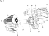
- FIG. 2 is a bottom perspective view showing the link-type driven former according to the present disclosure
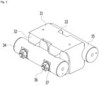
- FIG. 3 is a perspective view showing a connector part applied to the link-type driven former according to the present disclosure
- FIG. 4 is an exploded perspective view showing the connector part applied to the link-type driven former according to the present disclosure
- FIG. 5 is a view showing an operation process of the link-type driven former according to the present disclosure
- FIG. 6 is a graph showing a difference between the link-type driven former according to the present disclosure and a general former.
- a link-type driven former 1 is a device for processing a wire rod and forming the wire rod into parts such as bolts and pins.
- the link-type driven former may include at least one of a rotation guide shaft 10, an operation part 20, and a connector part 30.
- the link-type driven former 1 may move a drawing-out device 40 forward or backward so that the drawing-out device 40 hits and draws out a wire rod to be drawn out which is fitted into a forming mold, and in particular, improve a forming precision of a target to be drawn out which is formed by the forming mold by enabling the drawing-out device 40 to reach a front of the wire rod faster than a conventional former and making a time at which the drawing-out device 40 hits the wire rod slower than that of the conventional former when the drawing-out device 40 moves forward in order to draw out the wire rod formed by the forming mold.
- the link-type driven former 1 may include a revolve (not shown) formed with a plurality of movement guide holes having different diameters so as to guide the movement of the wire rod by diameter, a cutting unit (not shown) configured to gradually cut the wire rod transferred while being guided by the revolve, a tongs-holding type transformer configured to sequentially transfer the wire rod cut by the cutting unit to various forming molds, and a punch unit configured to insert the wire rod into a forming space provided inside the forming mold by hitting the wire rod from fronts of the forming molds. At this time, when the wire rod is hit by the punch unit, the wire rod is formed in the same shape as the forming space while being inserted into the forming space in a force-fitting manner.
- the cutting unit may cut the wire rod to various lengths by changing a cutting operation time.
- the cutting unit when the cutting unit operates quickly, the cutting unit may cut the wire rod to a short length, and in contrast, when the cutting unit operates slowly, the wire rod may be cut to a long length.
- the rotation guide shaft 10 is configured to guide a vertical rotation of the operation part 20.
- the rotation guide shaft 10 may be formed in a simple circular bar shape having the same outer diameter as a whole.
- the operation part 20 is mounted on the rotation guide shaft 10, and repeatedly rotated vertically by a drive source 50.
- the connector part 30 moves the drawing-out device 40 forward or backward repeatedly with respect to the forming mold by the vertical rotation of the operation part 20.
- the drawing-out device 40 When the drawing-out device 40 moves forward, the drawing-out device 40 draws out the wire rod from the forming mold by hitting the wire rod fitted into the forming mold.
- the drawing-out device 40 may include a ram 41 connected to the connector part 30, and a hitting portion 42 disposed at a front of the ram 41 and configured to hit and draw out the wire rod tightly fitted into the forming mold.
- the operation part 20 may include at least one of a base portion 21, a first member 22, a second member 23, and a first coupling shaft 24.
- the base portion 21 may be formed in a hollow shape and mounted on the rotation guide shaft 10.
- the first member 22 may be formed substantially in a lip shape.
- a plurality of first members 22 are applied and disposed on one side surface of the base portion 21, that is, a surface facing the connector part 30 to be spaced apart from each other in a width direction of the base portion 21.
- the first member 22 may be integrally formed with the base portion 21.
- the second member 23 may be formed substantially in a lip shape.
- a plurality of second members 23 are applied and disposed on the other side surface of the base portion 21 to be spaced apart from each other in the width direction of the base portion 21.
- the second member 23 may also be integrally formed with the base portion 21.
- the first member 22 and the second member 23 perform a seesaw motion with respect to the base portion 21.
- the second member 23 may be formed to have a length greater than that of the first member 22.
- the first member 22 may be formed to have a length of 30% to 80% of the length of the second member 23.
- a vertical rotation angle of the first member 22 is smaller than a vertical rotation angle of the second member 23.
- a first coupling shaft 24 coupled to the drive source 50 is installed to pass through the second member 23.
- a certain area of the first coupling shaft 24 is hidden inside the second member 23, and the other areas protrude between the second members 23.
- the drive source 50 may include a motor 51, a pulley 52, a timing belt connecting the motor 51 and the pulley 52, a first rotation shaft 54 having the pulley 52 eccentrically mounted at one side, a first gear 55 coupled to the other side of the first rotation shaft 54, a second rotation shaft 56 disposed at a bottom of the operation part 20, a second gear 57 mounted on the second rotation shaft 56 and engaged with the first gear 55, and a cam part 58 eccentrically coupled to each of one side and the other side of the second gear 57 to be rotated together with the second gear 57, wherein the cam part 58 has a protrusion bar 581, and a mounting ring 582 formed at an end of the protrusion bar 581 and mounted on the first coupling shaft 24 between the second members 23 formed at one side thereof.
- the timing belt is rotated while forming a caterpillar, and thus the pulley 52, the first rotation shaft 54, the second rotation shaft 56, the first gear 55, the second gear 57, and the cam part 58 are rotated uniformly.
- the protrusion bar 581 and the mounting ring 582 vertically rotate the operation part 20 by being rotated while drawing a curve when the cam part 58 is rotated.
- the connector part 30 pushes the ram 41 and thus the hitting portion 42 hits the wire rod fixed to the forming mold, and when the first member 22 is rotated upward, the connector part 30 pulls the ram 41 and thus the hitting portion 42 moves away from the forming mold.
- the wire rods formed by the forming mold may be hit at certain time intervals to be drawn out.
- the connector part 30 is a configuration that is coupled to the operation part 20 and the drawing-out device 40, and pulls and moves the drawing-out device 40 backward or pushes and moves the drawing-out device 40 forward due to the vertical rotation of the operation part 20.
- the connector part 30 may include at least one of a main body portion 31, a first protrusion piece 32, a second protrusion piece 33, a second coupling shaft 34, a third coupling shaft 35, a coupler 36, and a close-contact portion 37.
- the main body portion 31 is disposed between the first member 22 and the ram 41.
- the main body portion 31 may be formed in a substantially polygonal block shape.
- the first protrusion pieces 32 are disposed on one surface of the main body portion 31 to be spaced apart from each other, and each accommodated between the first members 22.
- the first member 22 positioned at a center in FIG. 1 is accommodated between the first protrusion pieces 32.
- first member 22 and the first protrusion piece 32 are horizontally engaged with each other.
- first accommodation groove 32a in which a certain area of the second coupling shaft 34 to be described below is accommodated, is formed in the first protrusion piece 32.
- the first accommodation groove 32a is formed in a semicircular shape.
- the second protrusion pieces 33 are disposed on the other surface of the main body portion 31 to be spaced apart from each other, and each accommodated in an accommodation space formed at an end of the ram 41.
- the second protrusion piece 33 faces the first protrusion piece 32 with the main body portion 31 interposed therebetween.
- An insertion piece 411 disposed on a central portion of the accommodation space of the ram 41 is inserted into a space between the second protrusion pieces 33.
- the second accommodation groove 33a in which a certain area of the third coupling shaft 35 to be described below is accommodated, is formed in the second protrusion piece 33.
- the third coupling shaft 35 is formed in a circular shape
- the second accommodation groove 33a is formed in a semicircular shape.
- the second coupling shaft 34 is coupled to the first member 22 to be rotatable in place.
- a certain area of the second coupling shaft 34 is hidden inside the first member 22, and the other areas protrude between the first members 22.
- the third coupling shaft 35 jointly passes through both sides of the ram 41 and the insertion piece 411.
- Both sides and a center of the third coupling shaft 35 are inserted into both sides of the ram 41 and the insertion piece 411, respectively, and the remaining portions protrude to the outside.
- the third coupling shaft 35 may be rotated in place at both sides of the ram 41 and the insertion piece 411.
- the couplers 36 are formed on one surface of the third coupling shaft 35 to be spaced apart from each other.
- the coupler 36 may be formed in a rod shape having a constant length and diameter.
- the couplers 36 having the same number as the through-holes 31a of the main body portion 31 are applied.
- couplers 36 face each of the through-holes 31a of the main body portion 31.
- each of the couplers 36 jointly passes through the second protrusion piece 33 and the main body portion 31, and the second protrusion piece 33 and the second coupling shaft 34.
- a certain area of the coupler 36 protrudes to the outside of the second coupling shaft 34.
- a spiral to which the close-contact portion 37 is fastened is formed in a protrusion area of the coupler 36.
- the close-contact portion 37 may be formed as a bolt.
- the close-contact portion 37 comes into close contact with an outer surface of the second coupling shaft 34 while being fastened to the spiral of the coupler 36 protruding to the outside of the second coupling shaft 34. Accordingly, the main body portion 31, the second coupling shaft 34, the third coupling shaft 35, and the coupler 36 are integrally coupled.
- the motor 51 is driven to rotate the timing belt 53 in a caterpillar form.
- the protrusion bar 581 repeatedly vertically rotates the second member 23 while being rotated together with the cam part 58.
- the first member 22 is positioned at a location higher than the rotation guide shaft 10
- the second member 23 is positioned at a location lower than the rotation guide shaft 10.
- the first member 22 is rotated upward, and the second member 23 is rotated downward.
- the connector part 30 is in a state of separating the hitting portion 42 from the forming mold by pulling the ram 41.
- FIG. 5B shows a state in which the cam part 58 rotates the second member 23 upward by rotation, and when the second member 23 rotates upward, the first member 22 is rotated downward.
- first member 22 and the second member 23 are parallel to each other with the base portion 21 interposed therebetween.
- the connector part 30 pushes the ram 41 to move the hitting portion 42 forward, and thus the hitting portion 42 hits and draws out the wire rod tightly fitted into the forming mold.
- the cam separates the hitting portion 42 from the wire rod of the drawing-out device 40 by pulling the ram 41 while forming an inclined shape in the form in which a left of the main body portion 31 is rotated upward and a right of the main body portion 31 is rotated downward.
- the main body portion 31 forms a horizontal shape together with the base portion 21, and at this time, the main body portion 31 gradually moves the ram 41 forward while being unfolded in the horizontal shape in a form in which an inclined angle is gradually smoothed in proportion to an angle at which the second member 23 is gradually rotated upward, and the first member 22 is gradually rotated downward.
- a time at which the hitting portion 42 reaches the vicinity (1 to 5 cm) of the wire rod of the forming mold can be faster than or equal to that of the conventional former, and a time point at which the hitting portion 42 hits the wire rod of the forming mold can be slower than that of the conventional former by about 1 second to 3 seconds.
- the link-type driven former may make the time point at which the hitting portion 42 hits the wire rod of the forming mold slower than that of the conventional former by about 1 second to 3 seconds, thereby preventing the occurrence of the situation in which the hitting portion 42 hits the wire rod before the forming mold forms the wire rod.
- a knuckle mechanism is added to a crank mechanism to have a motion curve in which forward speeds of the ram 41 and the hitting portion 411 become very slow around the wire rod that is a forging transfer point.
- the link-type driven former 1 it is possible to overcome a forming precision and a forming limit in a forging process of a hard-to-form material, reduce a forming load, reduce a deformation resistance, and the like by applying a power transmission structure to the knuckle crank mechanism structure.
Landscapes
- Engineering & Computer Science (AREA)
- Mechanical Engineering (AREA)
- Wire Processing (AREA)
- Forging (AREA)
- Press Drives And Press Lines (AREA)
- Moulds For Moulding Plastics Or The Like (AREA)
Applications Claiming Priority (1)
| Application Number | Priority Date | Filing Date | Title |
|---|---|---|---|
| KR1020220016645A KR102414683B1 (ko) | 2022-02-09 | 2022-02-09 | 링크방식 구동형 포머 |
Publications (1)
| Publication Number | Publication Date |
|---|---|
| EP4227019A1 true EP4227019A1 (fr) | 2023-08-16 |
Family
ID=82397073
Family Applications (1)
| Application Number | Title | Priority Date | Filing Date |
|---|---|---|---|
| EP22196880.3A Pending EP4227019A1 (fr) | 2022-02-09 | 2022-09-21 | Formeur entraîné de type à liaison |
Country Status (5)
| Country | Link |
|---|---|
| EP (1) | EP4227019A1 (fr) |
| JP (1) | JP7307511B1 (fr) |
| KR (1) | KR102414683B1 (fr) |
| CN (1) | CN116603971A (fr) |
| TW (1) | TWI836416B (fr) |
Families Citing this family (1)
| Publication number | Priority date | Publication date | Assignee | Title |
|---|---|---|---|---|
| CN118082079B (zh) * | 2024-04-23 | 2024-07-05 | 深圳市智联盛亚电子科技有限公司 | 一种智能手表用表带快速成型装置 |
Citations (5)
| Publication number | Priority date | Publication date | Assignee | Title |
|---|---|---|---|---|
| US2204043A (en) * | 1939-01-24 | 1940-06-11 | Greenwood & Batley Ltd | Cold forging machine |
| DE2028963A1 (en) * | 1970-06-12 | 1971-12-16 | Nedschroef Octrooi Maatschappij N V, Heimond (Niederlande) | Bolt forging machine |
| GB1431592A (en) * | 1972-08-24 | 1976-04-07 | Warnke Umformtech Veb K | Forging presses |
| JPS56137843U (fr) * | 1980-03-21 | 1981-10-19 | ||
| KR101539741B1 (ko) | 2014-11-12 | 2015-07-30 | 효동기계공업(주) | 제품 성형완성 후 제품에 흠집을 막기 위한 수직컨베이어를 구비하는 포머 |
Family Cites Families (13)
| Publication number | Priority date | Publication date | Assignee | Title |
|---|---|---|---|---|
| GB870436A (en) * | 1959-07-24 | 1961-06-14 | Giuseppe Cerutti | Automatic machine for the cold pressing of bolts |
| FR2118858B1 (fr) * | 1970-12-23 | 1973-12-28 | Aida Eng Ltd | |
| JPS5442739U (fr) * | 1977-08-30 | 1979-03-23 | ||
| JPS5797639U (fr) * | 1980-12-02 | 1982-06-16 | ||
| US6012322A (en) * | 1998-03-27 | 2000-01-11 | Aida Engineering Co., Ltd. | Slide-driving device for knuckle presses |
| TWI235688B (en) * | 2003-12-17 | 2005-07-11 | Wingtone Ind Co Ltd | Feeding mechanism for a forged part forming machine with adjustable feeding length |
| TWI247634B (en) * | 2003-12-17 | 2006-01-21 | Wingtone Ind Co Ltd | A driving device for post-forging mechanism and material-feeding mechanism of forming machine of cold-forged part |
| CN206824591U (zh) * | 2017-06-12 | 2018-01-02 | 温州展邦机械有限公司 | 应用于冷镦机的物料夹持装置 |
| CN107552713B (zh) * | 2017-09-06 | 2024-02-27 | 浙江展邦机械有限公司 | 螺丝成型机的成型模具切换装置 |
| CN107470545B (zh) * | 2017-09-06 | 2023-05-09 | 浙江展邦机械有限公司 | 螺丝成型机的切割成型装置 |
| CN214023120U (zh) * | 2020-11-06 | 2021-08-24 | 昆山东盟精密机械有限公司 | 一种笔记本散热金属件冲压成型设备 |
| CN113319240A (zh) * | 2021-06-30 | 2021-08-31 | 桐乡展裕电子科技有限公司 | 一种新型螺丝冷镦成型装置 |
| KR102346475B1 (ko) * | 2021-08-26 | 2022-01-03 | 효동기계공업(주) | 캠 자동 조절장치 |
-
2022
- 2022-02-09 KR KR1020220016645A patent/KR102414683B1/ko active Active
- 2022-04-14 JP JP2022067181A patent/JP7307511B1/ja active Active
- 2022-04-19 CN CN202210410565.1A patent/CN116603971A/zh active Pending
- 2022-05-03 TW TW111116715A patent/TWI836416B/zh active
- 2022-09-21 EP EP22196880.3A patent/EP4227019A1/fr active Pending
Patent Citations (5)
| Publication number | Priority date | Publication date | Assignee | Title |
|---|---|---|---|---|
| US2204043A (en) * | 1939-01-24 | 1940-06-11 | Greenwood & Batley Ltd | Cold forging machine |
| DE2028963A1 (en) * | 1970-06-12 | 1971-12-16 | Nedschroef Octrooi Maatschappij N V, Heimond (Niederlande) | Bolt forging machine |
| GB1431592A (en) * | 1972-08-24 | 1976-04-07 | Warnke Umformtech Veb K | Forging presses |
| JPS56137843U (fr) * | 1980-03-21 | 1981-10-19 | ||
| KR101539741B1 (ko) | 2014-11-12 | 2015-07-30 | 효동기계공업(주) | 제품 성형완성 후 제품에 흠집을 막기 위한 수직컨베이어를 구비하는 포머 |
Also Published As
| Publication number | Publication date |
|---|---|
| TWI836416B (zh) | 2024-03-21 |
| KR102414683B1 (ko) | 2022-07-01 |
| JP2023116373A (ja) | 2023-08-22 |
| JP7307511B1 (ja) | 2023-07-12 |
| CN116603971A (zh) | 2023-08-18 |
| TW202332641A (zh) | 2023-08-16 |
Similar Documents
| Publication | Publication Date | Title |
|---|---|---|
| US11165299B2 (en) | Coil assembling apparatus, coil assembling method and manufacturing apparatus of electrical rotating machine | |
| KR920004664B1 (ko) | 피라밋 대형의 캔몸체의 제조를 위한 방법 및 장치 | |
| US7480987B1 (en) | Method for pre-forming conductors for motor rotors and stators | |
| JP4327486B2 (ja) | 回転電機のコイル用のセグメントの成形装置、セグメントの成形方法及びそれを用いたセグメント | |
| US6810581B2 (en) | Crimping apparatus for sub-harness production employing movable connector tables securable to frame members | |
| WO2012015009A1 (fr) | Appareil pour fabrication de ressort hélicoïdal | |
| KR102414683B1 (ko) | 링크방식 구동형 포머 | |
| KR102346475B1 (ko) | 캠 자동 조절장치 | |
| CN111558640A (zh) | 自动弯管机 | |
| RU2440208C2 (ru) | Станок для изготовления соединительных стержней сетки | |
| US3946483A (en) | Apparatus for and method of removing a flexible tubular conduit from around an associated elongated rigid supporting mandrel | |
| JP2001008418A (ja) | ステータコアへの巻線装置 | |
| CN119812871A (zh) | 一种电子线束端子压接设备及其使用方法 | |
| JPS6240091B2 (fr) | ||
| JPH0795748A (ja) | 内溝ステータのワイヤ巻付装置 | |
| US4218877A (en) | Machine for making wooden chains | |
| CN219093429U (zh) | 一种用于冲床的自动送料装置 | |
| KR860001519B1 (ko) | 마그네트론의 제조방법과 장치 | |
| CN118880640B (zh) | 一种三角股钢丝绳成型系统 | |
| CN116851576B (zh) | 一种三通铜管的制造方法 | |
| KR102855835B1 (ko) | 열교환기용 동파이프 가공장치 | |
| US3134421A (en) | Method of and machine for cutting and forming articles | |
| KR100996254B1 (ko) | 케이블 행거 제조 장치 및 제조 방법 | |
| EP0104955A2 (fr) | Dispositif et procédé pour le tréfilage | |
| CN224143192U (zh) | 基于多轴同步导向联动的铝合金焊丝拉丝装置 |
Legal Events
| Date | Code | Title | Description |
|---|---|---|---|
| PUAI | Public reference made under article 153(3) epc to a published international application that has entered the european phase |
Free format text: ORIGINAL CODE: 0009012 |
|
| STAA | Information on the status of an ep patent application or granted ep patent |
Free format text: STATUS: REQUEST FOR EXAMINATION WAS MADE |
|
| 17P | Request for examination filed |
Effective date: 20220921 |
|
| AK | Designated contracting states |
Kind code of ref document: A1 Designated state(s): AL AT BE BG CH CY CZ DE DK EE ES FI FR GB GR HR HU IE IS IT LI LT LU LV MC MK MT NL NO PL PT RO RS SE SI SK SM TR |