EP4227075B1 - Plaques de pultrusion hybrides pour un capuchon de longeron conducteur d'une pale d'éolienne - Google Patents
Plaques de pultrusion hybrides pour un capuchon de longeron conducteur d'une pale d'éolienne Download PDFInfo
- Publication number
- EP4227075B1 EP4227075B1 EP22156266.3A EP22156266A EP4227075B1 EP 4227075 B1 EP4227075 B1 EP 4227075B1 EP 22156266 A EP22156266 A EP 22156266A EP 4227075 B1 EP4227075 B1 EP 4227075B1
- Authority
- EP
- European Patent Office
- Prior art keywords
- pultrusion
- fibre material
- glass fibre
- tows
- plate
- Prior art date
- Legal status (The legal status is an assumption and is not a legal conclusion. Google has not performed a legal analysis and makes no representation as to the accuracy of the status listed.)
- Active
Links
Images




Classifications
-
- F—MECHANICAL ENGINEERING; LIGHTING; HEATING; WEAPONS; BLASTING
- F03—MACHINES OR ENGINES FOR LIQUIDS; WIND, SPRING, OR WEIGHT MOTORS; PRODUCING MECHANICAL POWER OR A REACTIVE PROPULSIVE THRUST, NOT OTHERWISE PROVIDED FOR
- F03D—WIND MOTORS
- F03D1/00—Wind motors with rotation axis substantially parallel to the air flow entering the rotor
- F03D1/06—Rotors
- F03D1/065—Rotors characterised by their construction elements
- F03D1/0675—Rotors characterised by their construction elements of the blades
-
- B—PERFORMING OPERATIONS; TRANSPORTING
- B29—WORKING OF PLASTICS; WORKING OF SUBSTANCES IN A PLASTIC STATE IN GENERAL
- B29C—SHAPING OR JOINING OF PLASTICS; SHAPING OF MATERIAL IN A PLASTIC STATE, NOT OTHERWISE PROVIDED FOR; AFTER-TREATMENT OF THE SHAPED PRODUCTS, e.g. REPAIRING
- B29C70/00—Shaping composites, i.e. plastics material comprising reinforcements, fillers or preformed parts, e.g. inserts
- B29C70/04—Shaping composites, i.e. plastics material comprising reinforcements, fillers or preformed parts, e.g. inserts comprising reinforcements only, e.g. self-reinforcing plastics
- B29C70/06—Fibrous reinforcements only
- B29C70/08—Fibrous reinforcements only comprising combinations of different forms of fibrous reinforcements incorporated in matrix material, forming one or more layers, and with or without non-reinforced layers
-
- B—PERFORMING OPERATIONS; TRANSPORTING
- B29—WORKING OF PLASTICS; WORKING OF SUBSTANCES IN A PLASTIC STATE IN GENERAL
- B29C—SHAPING OR JOINING OF PLASTICS; SHAPING OF MATERIAL IN A PLASTIC STATE, NOT OTHERWISE PROVIDED FOR; AFTER-TREATMENT OF THE SHAPED PRODUCTS, e.g. REPAIRING
- B29C70/00—Shaping composites, i.e. plastics material comprising reinforcements, fillers or preformed parts, e.g. inserts
- B29C70/04—Shaping composites, i.e. plastics material comprising reinforcements, fillers or preformed parts, e.g. inserts comprising reinforcements only, e.g. self-reinforcing plastics
- B29C70/28—Shaping operations therefor
- B29C70/40—Shaping or impregnating by compression not applied
- B29C70/50—Shaping or impregnating by compression not applied for producing articles of indefinite length, e.g. prepregs, sheet moulding compounds [SMC] or cross moulding compounds [XMC]
- B29C70/52—Pultrusion, i.e. forming and compressing by continuously pulling through a die
-
- B—PERFORMING OPERATIONS; TRANSPORTING
- B29—WORKING OF PLASTICS; WORKING OF SUBSTANCES IN A PLASTIC STATE IN GENERAL
- B29D—PRODUCING PARTICULAR ARTICLES FROM PLASTICS OR FROM SUBSTANCES IN A PLASTIC STATE
- B29D99/00—Subject matter not provided for in other groups of this subclass
- B29D99/0025—Producing blades or the like, e.g. blades for turbines, propellers, or wings
- B29D99/0028—Producing blades or the like, e.g. blades for turbines, propellers, or wings hollow blades
-
- B—PERFORMING OPERATIONS; TRANSPORTING
- B29—WORKING OF PLASTICS; WORKING OF SUBSTANCES IN A PLASTIC STATE IN GENERAL
- B29K—INDEXING SCHEME ASSOCIATED WITH SUBCLASSES B29B, B29C OR B29D, RELATING TO MOULDING MATERIALS OR TO MATERIALS FOR MOULDS, REINFORCEMENTS, FILLERS OR PREFORMED PARTS, e.g. INSERTS
- B29K2307/00—Use of elements other than metals as reinforcement
- B29K2307/04—Carbon
-
- B—PERFORMING OPERATIONS; TRANSPORTING
- B29—WORKING OF PLASTICS; WORKING OF SUBSTANCES IN A PLASTIC STATE IN GENERAL
- B29K—INDEXING SCHEME ASSOCIATED WITH SUBCLASSES B29B, B29C OR B29D, RELATING TO MOULDING MATERIALS OR TO MATERIALS FOR MOULDS, REINFORCEMENTS, FILLERS OR PREFORMED PARTS, e.g. INSERTS
- B29K2309/00—Use of inorganic materials not provided for in groups B29K2303/00 - B29K2307/00, as reinforcement
- B29K2309/08—Glass
-
- B—PERFORMING OPERATIONS; TRANSPORTING
- B29—WORKING OF PLASTICS; WORKING OF SUBSTANCES IN A PLASTIC STATE IN GENERAL
- B29L—INDEXING SCHEME ASSOCIATED WITH SUBCLASS B29C, RELATING TO PARTICULAR ARTICLES
- B29L2031/00—Other particular articles
- B29L2031/08—Blades for rotors, stators, fans, turbines or the like, e.g. screw propellers
- B29L2031/082—Blades, e.g. for helicopters
- B29L2031/085—Wind turbine blades
-
- F—MECHANICAL ENGINEERING; LIGHTING; HEATING; WEAPONS; BLASTING
- F05—INDEXING SCHEMES RELATING TO ENGINES OR PUMPS IN VARIOUS SUBCLASSES OF CLASSES F01-F04
- F05B—INDEXING SCHEME RELATING TO WIND, SPRING, WEIGHT, INERTIA OR LIKE MOTORS, TO MACHINES OR ENGINES FOR LIQUIDS COVERED BY SUBCLASSES F03B, F03D AND F03G
- F05B2220/00—Application
- F05B2220/30—Application in turbines
-
- F—MECHANICAL ENGINEERING; LIGHTING; HEATING; WEAPONS; BLASTING
- F05—INDEXING SCHEMES RELATING TO ENGINES OR PUMPS IN VARIOUS SUBCLASSES OF CLASSES F01-F04
- F05B—INDEXING SCHEME RELATING TO WIND, SPRING, WEIGHT, INERTIA OR LIKE MOTORS, TO MACHINES OR ENGINES FOR LIQUIDS COVERED BY SUBCLASSES F03B, F03D AND F03G
- F05B2230/00—Manufacture
- F05B2230/20—Manufacture essentially without removing material
- F05B2230/23—Manufacture essentially without removing material by permanently joining parts together
-
- F—MECHANICAL ENGINEERING; LIGHTING; HEATING; WEAPONS; BLASTING
- F05—INDEXING SCHEMES RELATING TO ENGINES OR PUMPS IN VARIOUS SUBCLASSES OF CLASSES F01-F04
- F05B—INDEXING SCHEME RELATING TO WIND, SPRING, WEIGHT, INERTIA OR LIKE MOTORS, TO MACHINES OR ENGINES FOR LIQUIDS COVERED BY SUBCLASSES F03B, F03D AND F03G
- F05B2240/00—Components
- F05B2240/20—Rotors
- F05B2240/30—Characteristics of rotor blades, i.e. of any element transforming dynamic fluid energy to or from rotational energy and being attached to a rotor
-
- F—MECHANICAL ENGINEERING; LIGHTING; HEATING; WEAPONS; BLASTING
- F05—INDEXING SCHEMES RELATING TO ENGINES OR PUMPS IN VARIOUS SUBCLASSES OF CLASSES F01-F04
- F05B—INDEXING SCHEME RELATING TO WIND, SPRING, WEIGHT, INERTIA OR LIKE MOTORS, TO MACHINES OR ENGINES FOR LIQUIDS COVERED BY SUBCLASSES F03B, F03D AND F03G
- F05B2280/00—Materials; Properties thereof
- F05B2280/60—Properties or characteristics given to material by treatment or manufacturing
- F05B2280/6003—Composites; e.g. fibre-reinforced
-
- Y—GENERAL TAGGING OF NEW TECHNOLOGICAL DEVELOPMENTS; GENERAL TAGGING OF CROSS-SECTIONAL TECHNOLOGIES SPANNING OVER SEVERAL SECTIONS OF THE IPC; TECHNICAL SUBJECTS COVERED BY FORMER USPC CROSS-REFERENCE ART COLLECTIONS [XRACs] AND DIGESTS
- Y02—TECHNOLOGIES OR APPLICATIONS FOR MITIGATION OR ADAPTATION AGAINST CLIMATE CHANGE
- Y02E—REDUCTION OF GREENHOUSE GAS [GHG] EMISSIONS, RELATED TO ENERGY GENERATION, TRANSMISSION OR DISTRIBUTION
- Y02E10/00—Energy generation through renewable energy sources
- Y02E10/70—Wind energy
- Y02E10/72—Wind turbines with rotation axis in wind direction
-
- Y—GENERAL TAGGING OF NEW TECHNOLOGICAL DEVELOPMENTS; GENERAL TAGGING OF CROSS-SECTIONAL TECHNOLOGIES SPANNING OVER SEVERAL SECTIONS OF THE IPC; TECHNICAL SUBJECTS COVERED BY FORMER USPC CROSS-REFERENCE ART COLLECTIONS [XRACs] AND DIGESTS
- Y02—TECHNOLOGIES OR APPLICATIONS FOR MITIGATION OR ADAPTATION AGAINST CLIMATE CHANGE
- Y02P—CLIMATE CHANGE MITIGATION TECHNOLOGIES IN THE PRODUCTION OR PROCESSING OF GOODS
- Y02P70/00—Climate change mitigation technologies in the production process for final industrial or consumer products
- Y02P70/50—Manufacturing or production processes characterised by the final manufactured product
Definitions
- the present invention relates to a method of manufacturing a wind turbine blade shell component and to a reinforcing structure, such as a spar cap, for a wind turbine blade, the reinforcing structure comprising a plurality of pultrusion plates.
- Wind turbines typically comprise a tower, generator, gearbox, nacelle, and one or more rotor blades, which capture kinetic energy of wind using known airfoil principles. With increasing energy demand, modern wind turbines can have power ratings of above 10 MW and may have rotor blades that exceed 100 meters in length.
- Wind turbine blades are typically made from a fibre-reinforced polymer material and comprise a pressure side shell half and a suction side shell half.
- the cross-sectional profile of a typical blade includes an airfoil for creating an air flow leading to a pressure difference between both sides. The resulting lift force generates torque for producing electricity.
- Wind turbine blades are usually manufactured by forming two shell parts or shell halves from layers of woven fabric or fibre and resin.
- Spar caps or main laminates are placed or integrated in the shell halves and may be combined with shear webs or spar beams to form structural support members. Spar caps or main laminates may be joined to, or integrated within, the inside of the suction and pressure halves of the shell.
- a spar cap in a wind turbine blade is made from either carbon pultrusions or glass pultrusions. Carbon fibres are typically lighter than glass fibres by volume, and have improved tensile and compressive strength.
- a lightning protection system of the blade often requires that at least some blade components have a sufficiently high electrical conductivity through the thickness of the components, such as reinforcing sections like spar caps.
- an existing challenge of known pultrusion processes is to obtain a correct and consistent placement of the fibre material.
- Some of the known techniques make it difficult to control the fibre location and to maintain the correct distribution within the pultruded article.
- this method allows for a significantly improved control of the architecture of the pultrusion plate, in particular with respect to the correct positioning of the carbon fibre material and the glass fibre material. Since the glass fibre material is held together or consolidated, preferably at the centre of the pultrusion plate, it can be ensured that the adjacent or surrounding carbon fibre material is distributed and maintained at the correct location. Using one or more of the suggested approaches to consolidate or hold together the glass fibre material, i.e.
- a glass fibre fabric (i) a glass fibre preform comprising a consolidated arrangement of glass fibres and a binding agent, or (iii) a plurality of glass fibres encapsulated by a veil or a foil, provides an even and well-defined distribution of the carbon fibre material in the hybrid pultrusion process. This, in turn, is critical for the intended use of the pultrusion plates, i.e., as part of a lightning protection system of the wind turbined blade.
- this method and structure of the pultrusion plate are found to enhance the lightning protection properties and structural performance of the blade.
- the present solution reduces the risk for flaring over the pultrusion spar beam.
- structural and lightning protection performance can be enhanced at minimum material cost.
- Carbon fibres usually have high electrical conductivity and high stiffness per weight. These properties are desirable in the spar cap of a wind turbine blade.
- drawbacks of carbon fibres include the relatively low strain to failure and the comparatively high price per kg.
- Glass fibres are typically cheaper and have higher strain to failure.
- the electrical conductivity of glass fibres is minimal and stiffness per weight is significantly lower.
- the glass fibre material of the pultrusion plate is surrounded by the carbon fibre material.
- the glass fibre material of the pultrusion plate is surrounded by the carbon fibre material along the lateral surfaces and along the top and bottom surfaces of the pultrusion plate.
- the glass fibre fabric, the glass fibre preform or the plurality of glass fibres encapsulated by a veil or a foil are encapsulated with carbon fibres.
- the glass fibre material is a glass fibre fabric.
- the glass fibre fabric is a stitched fabric, a woven fabric, a knit fabric, a nonwoven fabric or a continuous filament mat.
- the glass fibre fabric is a UD-fabric that is woven or stitched.
- the glass fibre material is a glass fibre preform comprising a consolidated arrangement of glass fibres and a binding agent.
- the glass fibre preform preferably comprises a glass fibre material which is at least partially joined together by means of the binding agent, wherein the binding agent is preferably present in an amount of 0.1-15 wt% relative to the weight of the fibre material of the preform.
- the glass fibre material comprises, or consists of, glass fibre rovings.
- the binding agent is present in an amount of 0.1-15 wt% relative to the weight of the fibre material.
- the binding agent is a thermoplastic binding agent.
- the fibre material is at least partially joined together by means of the binding agent by thermal bonding.
- the binding agent for preparing the preform could be a binding powder, such as a thermoplastic binding powder.
- the binding agent of the preform is present in an amount of 0.5-10 wt%, preferably 0.5-5 wt%, more preferably 0.5-3.5 wt%, relative to the weight of the fibre material in the preform.
- the binding agent may also comprise two or more different substances.
- the melting point of the binding agent is between 40° and 220 °C, preferably between 40 and 180 °C, such as between 40 and 170 °C, or between 40 and 160 °C.
- the binding agent comprises a polyester, preferably a bisphenolic polyester.
- An example of such binding agent is a polyester marketed under the name NEOXIL 940.
- the glass fibre preform comprises multiple glass fibre layers stacked on top of each other.
- the multiple glass fibre layers such as three or more glass fibre layers, may be consolidated or bound together by, for example, a binding agent or an adhesive, or by a stitching.
- the glass fibre preform comprises glass fibre rovings.
- each tow comprises a plurality of carbon filaments, wherein each filament comprises an outer layer of sizing.
- each pultrusion plate preferably comprises a resin or binding agent which is used in the pultrusion process for joining the carbon fibre material and the glass fibre material into a single pultrusion string.
- each pultrusion plate comprises a matrix of fibre tows arranged in columns and rows, as seen in a vertical cross section of the plate.
- pultrusion fibre material may comprise glass fibres, carbon fibres, a resin or binding agent, and optionally additional reinforcing material.
- the pultrusion plate has a constant cross-section along its length.
- the pultrusion plates are arranged into adjacent stacks of pultrusion plates, and wherein a continuous path of adjoining tows of carbon fibre material extends from the top surface of the uppermost pultrusion plate to the bottom surface of the lowermost pultrusion plate of each stack of pultrusion plates.
- Said continuous path of adjoining tows of carbon fibre material within the stack is preferably an electrically conducting path.
- the entire stack may conduct a lightning current from the top surface of the stack to the bottom surface of the stack, preferably in a substantially vertical or flapwise direction.
- the lateral surfaces of the pultrusion plate are free from glass fibres, preferably by providing a continuous path of adjoining tows of carbon fibre material along the lateral edges of the pultrusion plate, the continuous path of adjoining tows of carbon fibre material extending from the top surface to the opposing bottom surface of the pultrusion plate.
- the glass fibre material and the carbon fibre material form a non-random pattern, preferably a symmetrical pattern, as seen in a vertical cross section of the pultrusion plate.
- the top and bottom surfaces of the pultrusion plate may be covered by peel ply.
- the pultrusion plates have a length corresponding to an entire length of a spar cap for a wind turbine blade shell.
- the pultrusion plates are bonded with the blade shell material in a resin infusion process.
- the pultrusion plate has a rectangular cross section. In a preferred embodiment, the pultrusion plate has the shape of a rectangular cuboid.
- the pultrusion plate has a length, which typically extend in a substantially spanwise direction when the pultrusion plate is arranged in the blade shell.
- the pultrusion plate also has a width, which typically extends in a substantially chordwise direction when the pultrusion plate is arranged in the blade shell.
- the pultrusion plate also has a height or thickness, which typically extends in a substantially flapwise direction when the pultrusion plate is arranged in the blade shell.
- the thickness of the pultrusion plate is preferably between 3 and 10 mm, more preferably between 4 and 7 mm.
- the length of the plate is typically its largest dimension. The length of the plate extends in the same direction as its longitudinal axis.
- the length of the pultrusion plate is typically between 50 and 150 meters, preferably between 50 and 100 meters, more preferably between 70 and 100 meters.
- the height/thickness of the pultrusion plate is preferably between 2 and 10 millimeters, preferably between 3 and 7 millimeters, most preferably between 4 and 6 millimeters.
- the width of the plate is preferably between 20 and 300 millimeters, most preferably between 80 and 150 millimeters.
- the reinforcing structure, such as the spar cap comprises between 1 and 15 stacks of pultrusion plates arranged next to each other, more preferably between 3 and 9 stacks.
- the wind turbine blade is usually manufactured from two shell halves, a pressure side shell half and a suction side shell half.
- both shell halves comprise an elongate reinforcing structure, such as a spar cap or a main laminate, according to the present invention.
- the present invention relates to a wind turbine blade or to a wind turbine blade component comprising a reinforcing structure according to the present invention, or to a wind turbine blade shell component obtainable by the afore-mentioned method of manufacturing a wind turbine blade shell component.
- the present invention relates to a wind turbine blade shell component comprising a plurality of pultrusion plates according to the present invention.
- the present invention also relates to a lightning protection system for a wind turbine blade, the lightning protection system comprising a lightning conductor, such as a cable, for example a copper cable, disposed at least partially in the interior of the blade, one or more electrically conducting lightning receptors disposed on one or more of the surfaces of the blade, wherein the one or more electrically conducting lightning receptors are electrically connected to a plurality of pultrusion plates according to the present invention, or to a reinforcing structure, such as a spar cap, of the present invention.
- the present invention relates to a wind turbine blade comprising a lightning protection system as described above, i.e.
- the lightning protection system comprising a lightning conductor, such as a cable, for example a copper cable, disposed at least partially in the interior of the blade, one or more electrically conducting lightning receptors disposed on one or more of the surfaces of the blade, wherein the one or more electrically conducting lightning receptors are electrically connected to a plurality of pultrusion plates according to the present invention, or to a reinforcing structure, such as a spar cap, of the present invention.
- a lightning conductor such as a cable, for example a copper cable
- the shell halves will typically be produced by infusing a fibre lay-up of fibre material with a resin such as epoxy, polyester or vinyl ester.
- a resin such as epoxy, polyester or vinyl ester.
- the pressure side shell half and the suction side shell half are manufactured using a blade mould.
- Each of the shell halves may comprise spar caps or main laminates provided along the respective pressure and suction side shell members as reinforcing structures.
- the spar caps or main laminates may be affixed to the inner faces of the shell halves.
- the present invention relates to a pultrusion process for manufacturing the pultrusion plate of the present invention, and to a pultrusion plate obtainable by said pultrusion process.
- Said pultrusion process preferably comprises the provision of a plurality of bobbins carrying respective tows of carbon fibre material.
- a centre reinforcement material is provided in the form of a glass fibre fabric, a glass fibre preform comprising a fibre material, or a glass fibre material encapsulated by a veil or foil, as further explained above.
- the tows of carbon fibre material and the centre reinforcement material are preferably pulled through guide plates, a resin bath, and a heated die by a pulling mechanism.
- the continuous pultrusion string can be cut into individual pultrusion plates with a length of between 30-200 meters, preferably 50-100 meters, by a cutter.
- the shaped impregnated plates are then advantageously cured.
- the guide plates and/or the die may take the form of a spreader or inlet comprising multiple apertures, some of the apertures receiving a respective carbon fibre tow, and other apertures receiving the glass fibre material, preferably a glass fibre fabric or preform.
- the apertures can be spaced and they are located so as to guide the fibre to form a desired pattern of glass fibre material and carbon fibre material in the pultrusion plates.
- spanwise is used to describe the orientation of a measurement or element along the blade from its root end to its tip end. In some embodiments, spanwise is the direction along the longitudinal axis and longitudinal extent of the wind turbine blade.
- the term "horizontal” refers to a direction that is substantially parallel to the chord of the blade when the pultrusion plates are arranged in the blade shell.
- the vertical direction is substantially perpendicular to the horizontal direction, extending in a substantially flapwise direction of the blade.
- the pressure side shell part 36 may also comprise a sandwich core material 43 typically made of balsawood or foamed polymer and sandwiched between a number of fibre-reinforced skin layers.
- the sandwich core material 43 is used to provide stiffness to the shell in order to ensure that the shell substantially maintains its aerodynamic profile during rotation of the blade.
- the suction side shell part 38 may also comprise a sandwich core material 47.
- the spar cap 41 of the pressure side shell part 36 and the spar cap 45 of the suction side shell part 38 are connected via a first shear web 50 and a second shear web 55.
- the shear webs 50, 55 are in the shown embodiment shaped as substantially I-shaped webs.
- the first shear web 50 comprises a shear web body and two web foot flanges.
- the shear web body comprises a sandwich core material 51, such as balsawood or foamed polymer, covered by a number of skin layers 52 made of a number of fibre layers.
- the blade shells 36, 38 may comprise further fibre-reinforcement at the leading edge and the trailing edge. Typically, the shell parts 36, 38 are bonded to each other via glue flanges.
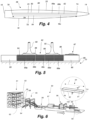
- Fig. 4 is a schematic top view of a shell half 38 of a wind turbine blade according to the present invention, illustrating the location of a reinforcing structure 62 having a spanwise extent Se.
- the reinforcing structure 62 comprises three adjacent stacks 66a, 66b, 66c of pultrusion plates.
- the elongate reinforcing structure 62 extends in a substantially spanwise direction of the blade, with adjacent stacks 66a, 66b, 66c of pultrusion plates.
- the elongate reinforcing structure 62 has a tip end 74, closest to the tip end of the blade, and a root end 76, closest to the root end of the blade.
- the elongate reinforcing structure also comprises a spanwise extending front edge 78, which is closest to the leading edge 18 of the blade, and a spanwise extending rear edge 80, which is closest to the trailing edge 20 of the blade.
- Fig. 6 illustrates a pultrusion process for manufacturing the pultrusion plates 64 of the present invention.
- the pultrusion process makes use of a pultrusion system 90 which comprises a portion for receiving a plurality of bobbins 93 each supply a tow of carbon fibre material 68 from a creel 91.
- a centre reinforcement material 94 is provided in the form of a glass fibre fabric, a glass fibre preform comprising a fibre material, or a glass fibre material encapsulated by a veil or foil, as further explained below.
- the tows 68 and the glass fibre fabric 94 are pulled through guide plates 95, resin bath 96, and heated die 97 by pulling mechanism 98.
- the pultrusion string 100 is cut into individual pultrusion plates 64 by cutter 99.
- the shaped impregnated fibres are cured and can optionally be wound onto a roll.
- the guide plates and/or the die may take the form of a spreader or inlet comprising multiple apertures, each aperture receiving a respective carbon fibre tow or glass fibre two.
- the apertures can be spaced and they are located so as to guide the fibre tows and the fabric/preform/encapsulated glass fibre part to form a desired pattern of glass fibre material and carbon fibre material in the pultrusion plates 64.
- the enlarged view of the pultrusion plate 64 in Fig. 6 also illustrates its longitudinal axis La and its length l.
- the height/thickness h and width w of the pultrusion plate are illustrated in Fig. 8 , see plate 64f.
- Each pultrusion plate 64 in the various embodiments illustrated in Figs. 7a-f comprises a plurality of tows of glass fibre material 70, indicated as white elliptical shapes, and a plurality of tows ofcarbon fibre material 68, indicated as black elliptical shapes.
- the tows of glass fibre material 70 and the tows of carbon fibre material 68 are arranged in an array of rows 71 and columns 72 of tows, as seen in a vertical cross section of the pultrusion plate.
- each pultrusion plate comprises a top surface 81, an opposing bottom surface 82 and two lateral surfaces 83, 84, wherein adjoining tows of carbon fibre material are provided along the lateral surfaces 83, 84.
- This provides respective continuous paths 67a, 67b of adjoining tows of carbon fibre material extending from the top surface 81 to the opposing bottom surface 82 of the pultrusion plate 64 along the lateral surfaces.
- the plurality of tows of glass fibre material 70 and the plurality of tows of carbon fibre material 68 form a non-random pattern, preferably a symmetrical pattern, as seen in a vertical cross section of the pultrusion plate 64.
- Fig. 7a shows an embodiment where adjoining tows of carbon fibre material are only provided along the lateral surfaces 83, 84.
- the carbon tows additionally extend along part of the upper and lower surfaces 81, 82, to some extent from the lateral surfaces 83, 84 towards the centre.
- Fig. 7a shows an embodiment where adjoining tows of carbon fibre material are only provided along the lateral surfaces 83, 84.
- the carbon tows additionally extend along part of the upper and lower surfaces 81, 82, to some extent from the lateral surfaces 83, 84 towards the centre.
- the carbon tows additionally extend along the upper and lower surfaces 81, 82 across the entire width of the pultrusion plate.
- the embodiment illustrated in Fig. 7d comprises several rows of adjoining carbon tows 68 along the lateral surfaces, as well as a continuous line of carbon tows extending between the lateral edges within the pultrusion plate.
- Fig. 7e illustrates a similar configuration in which several rows of adjoining carbon tows 68 are provided along the lateral surfaces, and in addition a checkerboard pattern is provided in a centre region of the pultrusion plate 64.
- Fig. 9 is a cross sectional view of another embodiment of a pultrusion plate 64.
- adjoining tows of carbon fibre material 68 are provided along the top surface 81 and the bottom surface 82 of the pultrusion plate, whereas the lateral edges 83, 84 comprise both carbon fibre tows and glass fibre tows.
- a conductive path of adjoining carbon fibre tows is provided in a horizontal direction.
- Fig. 10 is a schematic vertical cross-sectional view of yet additional embodiments of a pultrusion plate.
- the plurality of tows of glass fibre material 70 and the plurality of tows of carbon fibre material 68 form a non-random pattern as seen in a vertical cross section of the pultrusion plate 64.
- adjoining tows of carbon fibre material are provided along the lateral surfaces 83, 84.
- a continuous line of carbon tows extends through the centre, between the lateral edges of the pultrusion plate.
- Fig. 10b shows an embodiment wherein a vertical column extends at the centre of the plate, however, without extending all the way to the top surface or to the bottom surface.
- a pultrusion plate 64 of the present invention is illustrated in Fig. 14 , which is a schematic vertical cross-sectional view taken along the line a-a' in Fig. 6 .
- the glass fibre material at the centre of the plate is a glass fibre preform 112, which may be composed of a consolidated arrangement of glass fibres, such as glass fibre layers 114a-d, which are consolidated by a binding agent.
- Fig. 15 illustrates a third embodiment of a pultrusion plate according to the present invention, which comprises a plurality of glass fibres, such as tows 70 of glass fibre material, encapsulated by a veil or a foil 116. Again, this glass fibre arrangement is surrounded by a plurality of tows 68 of carbon fibre material.
- the glass fibre fabric 110, the glass fibre preform 112 or the plurality of glass fibres encapsulated by a veil 116 or a foil are joined with the carbon fibre material, such as a plurality of tows of carbon fibre material in the pultrusion process, as illustrated in Fig. 6 wherein the reference numeral 94 denotes the glass fibre fabric, the glass fibre preform or the plurality of glass fibres encapsulated by a veil or a foil.
Landscapes
- Engineering & Computer Science (AREA)
- Mechanical Engineering (AREA)
- Chemical & Material Sciences (AREA)
- Composite Materials (AREA)
- Life Sciences & Earth Sciences (AREA)
- Sustainable Development (AREA)
- Sustainable Energy (AREA)
- Combustion & Propulsion (AREA)
- General Engineering & Computer Science (AREA)
- Moulding By Coating Moulds (AREA)
Claims (15)
- Procédé de fabrication d'un composant de coque de pale d'éolienne (38), le procédé comportant les étapes consistant àmettre en œuvre une pluralité de plaques de pultrusion (64), dans lequel chaque plaque de pultrusion (64) comporte une surface supérieure (81), une surface inférieure opposée (82) et deux surfaces latérales (83, 84),agencer les plaques de pultrusion (64) sur un matériau de coque de pale (89) dans un moule (77) pour le composant de coque de pale, etlier les plaques de pultrusion (64) avec le matériau de coque de pale pour former le composant de coque de pale,dans lequel chaque plaque de pultrusion (64) est formée à partir d'un matériau de pultrusion à base de fibres comportant un matériau à base de fibres de verre (70) et un matériau à base de fibres de carbone (68), caractérisé en ce que le matériau à base de fibres de carbone est mis en œuvre le long de la totalité des surfaces latérales (83, 84) de la plaque de pultrusion, et dans lequel le matériau à base de fibres de verre est choisi parmiun tissu à base de fibres de verre (110),une préforme à base de fibres de verre (112) comportant un agencement consolidé de fibres de verre (114) et d'un liant, etune pluralité de fibres de verre encapsulées par un voile ou une feuille (116).
- Procédé selon la revendication 1, dans lequel la préforme à base de fibres de verre comporte de multiples couches de fibres de verre empilées les unes sur les autres.
- Procédé selon la revendication 1 ou la revendication 2, dans lequel le tissu à base de fibres de verre est un tissu cousu, un tissu tissé, un tissu tricoté, un tissu non tissé ou un mat de filaments continus.
- Procédé selon l'une quelconque des revendications précédentes, dans lequel la préforme à base de fibres de verre comporte des stratifils en fibres de verre.
- Procédé selon l'une quelconque des revendications précédentes, dans lequel le matériau à base de fibres de carbone comporte une pluralité d'étoupes de matériau à base de fibres de carbone (68), et dans lequel des étoupes contiguës de matériau à base de fibres de carbone sont mises en œuvre le long de la totalité des surfaces latérales (83, 84) de la plaque de pultrusion.
- Procédé selon l'une quelconque des revendications précédentes, dans lequel les surfaces latérales de chaque plaque de pultrusion sont exemptes de fibres de verre, de préférence par la mise en œuvre d'un trajet continu d'étoupes contiguës de matériau à base de fibres de carbone le long des bords latéraux de la plaque de pultrusion, le trajet continu d'étoupes contiguës de matériau à base de fibres de carbone s'étendant de la surface supérieure à la surface inférieure opposée de la plaque de pultrusion, et dans lequel le trajet continu d'étoupes contiguës de matériau à base de fibres de carbone procure un trajet électriquement conducteur dans l'ensemble de la direction verticale de la plaque de pultrusion.
- Procédé selon l'une quelconque des revendications précédentes, dans lequel les plaques de pultrusion sont agencées en piles adjacentes de plaques de pultrusion, et dans lequel un trajet continu (67) d'étoupes contiguës de matériau à base de fibres de carbone s'étend de la surface supérieure de la plaque de pultrusion se trouvant le plus en haut à la surface inférieure de la plaque de pultrusion se trouvant le plus en bas de chaque pile de plaques de pultrusion.
- Plaque de pultrusion (64) comportant une surface supérieure (81), une surface inférieure opposée (82) et deux surfaces latérales (83, 84), dans laquelle la plaque de pultrusion est formée à partir d'un matériau de pultrusion à base de fibres comportant un matériau à base de fibres de verre (70) et un matériau à base de fibres de carbone (68), caractérisée en ce que le matériau à base de fibres de carbone est mis en œuvre le long de la totalité des surfaces latérales (83, 84) de la plaque de pultrusion, et dans laquelle le matériau à base de fibres de verre est choisi parmiun tissu à base de fibres de verre,une préforme à base de fibres de verre comportant un agencement consolidé de fibres de verre et d'un liant, etune pluralité de fibres de verre encapsulées par un voile ou une feuille.
- Plaque de pultrusion selon la revendication 8, dans laquelle la préforme à base de fibres de verre comporte de multiples couches de fibres de verre empilées les unes sur les autres.
- Plaque de pultrusion selon la revendication 8 ou la revendication 9, dans laquelle le tissu à base de fibres de verre est un tissu cousu, un tissu tissé, un tissu tricoté, un tissu non tissé ou un mat de filaments continus.
- Plaque de pultrusion selon l'une quelconque des revendications 8 à 10, dans laquelle la préforme à base de fibres de verre comporte des stratifils en fibres de verre.
- Plaque de pultrusion selon l'une quelconque des revendications 8 à 11, dans laquelle le matériau à base de fibres de carbone comporte une pluralité d'étoupes de matériau à base de fibres de carbone (68), et dans laquelle des étoupes contiguës de matériau à base de fibres de carbone sont mises en œuvre le long de la totalité des surfaces latérales (83, 84) de la plaque de pultrusion.
- Structure de renforcement pour une pale d'éolienne, la structure de renforcement comportant une pluralité de plaques de pultrusion (64) selon l'une quelconque des revendications 8 à 12.
- Composant de coque de pale d'éolienne comportant une pluralité de plaques de pultrusion (64) selon l'une quelconque des revendications 8 à 12.
- Système de protection contre la foudre (102) pour une pale d'éolienne, le système de protection contre la foudre comportant un conducteur de paratonnerre (104) disposé au moins partiellement à l'intérieur de la pale, un ou plusieurs récepteurs de foudre électriquement conducteurs (106, 107, 108) disposés sur une ou plusieurs des surfaces de la pale, dans lequel lesdits un ou plusieurs récepteurs de foudre électriquement conducteurs sont connectés électriquement à une semelle de longeron, dans lequel la semelle de longeron comporte une pluralité de plaques de pultrusion (64) selon l'une quelconque des revendications 8 à 12.
Priority Applications (6)
| Application Number | Priority Date | Filing Date | Title |
|---|---|---|---|
| ES22156266T ES3030137T3 (en) | 2022-02-11 | 2022-02-11 | Hybrid pultrusion plates for a conductive spar cap of a wind turbine blade |
| EP22156266.3A EP4227075B1 (fr) | 2022-02-11 | 2022-02-11 | Plaques de pultrusion hybrides pour un capuchon de longeron conducteur d'une pale d'éolienne |
| DK22156266.3T DK4227075T3 (da) | 2022-02-11 | 2022-02-11 | Hybride pultruderingsplader til en ledende bjælkeflange i en vindmøllevinge |
| US18/718,607 US20240401560A1 (en) | 2022-02-11 | 2023-02-03 | Improved hybrid pultrusion plates for a conductive spar cap of a wind turbine blade |
| PCT/EP2023/052712 WO2023152053A1 (fr) | 2022-02-11 | 2023-02-03 | Plaques de pultrusion hybrides pour une semelle de longeron conductrice d'une pale d'éolienne |
| CN202380020945.7A CN118679051A (zh) | 2022-02-11 | 2023-02-03 | 用于风力涡轮机叶片的传导性翼梁帽的混合拉挤板 |
Applications Claiming Priority (1)
| Application Number | Priority Date | Filing Date | Title |
|---|---|---|---|
| EP22156266.3A EP4227075B1 (fr) | 2022-02-11 | 2022-02-11 | Plaques de pultrusion hybrides pour un capuchon de longeron conducteur d'une pale d'éolienne |
Publications (2)
| Publication Number | Publication Date |
|---|---|
| EP4227075A1 EP4227075A1 (fr) | 2023-08-16 |
| EP4227075B1 true EP4227075B1 (fr) | 2025-03-26 |
Family
ID=80446335
Family Applications (1)
| Application Number | Title | Priority Date | Filing Date |
|---|---|---|---|
| EP22156266.3A Active EP4227075B1 (fr) | 2022-02-11 | 2022-02-11 | Plaques de pultrusion hybrides pour un capuchon de longeron conducteur d'une pale d'éolienne |
Country Status (6)
| Country | Link |
|---|---|
| US (1) | US20240401560A1 (fr) |
| EP (1) | EP4227075B1 (fr) |
| CN (1) | CN118679051A (fr) |
| DK (1) | DK4227075T3 (fr) |
| ES (1) | ES3030137T3 (fr) |
| WO (1) | WO2023152053A1 (fr) |
Family Cites Families (18)
| Publication number | Priority date | Publication date | Assignee | Title |
|---|---|---|---|---|
| GB1373782A (en) * | 1972-10-05 | 1974-11-13 | English Electric Co Ltd | Manufacture of reinforced plastics |
| US5279879A (en) * | 1989-12-28 | 1994-01-18 | Tonen Corporation | Hybrid prepreg containing carbon fibers and at least one other reinforcing fiber in specific positions within the prepreg |
| US5910458A (en) * | 1997-05-30 | 1999-06-08 | Ppg Industries, Inc. | Glass fiber mats, thermosetting composites reinforced with the same and methods for making the same |
| CN102123852B (zh) * | 2008-04-30 | 2014-03-19 | 维斯塔斯风力系统有限公司 | 固结复合预制件 |
| PL3024645T3 (pl) * | 2013-07-26 | 2024-04-29 | Lm Wind Power A/S | Sposób wytwarzania co najmniej części łopaty turbiny wiatrowej |
| US20160146184A1 (en) * | 2014-11-25 | 2016-05-26 | General Electric Company | Methods of manufacturing rotor blade components for a wind turbine |
| US9745956B2 (en) * | 2014-12-10 | 2017-08-29 | General Electric Company | Spar cap for a wind turbine rotor blade |
| US20170058869A1 (en) * | 2015-08-27 | 2017-03-02 | General Electric Company | Conduit assembly for a lightning protection cable of a wind turbine rotor blade |
| US10107257B2 (en) * | 2015-09-23 | 2018-10-23 | General Electric Company | Wind turbine rotor blade components formed from pultruded hybrid-resin fiber-reinforced composites |
| US10213994B2 (en) * | 2015-09-23 | 2019-02-26 | General Electric Company | Methods for manufacturing spar caps for wind turbine rotor blades using thermoplastic-based composite plates |
| US10113532B2 (en) * | 2015-10-23 | 2018-10-30 | General Electric Company | Pre-cured composites for rotor blade components |
| JP2018118440A (ja) * | 2017-01-25 | 2018-08-02 | 旭硝子株式会社 | 引抜成形体及びその製造方法 |
| US10619622B2 (en) * | 2017-06-21 | 2020-04-14 | General Electric Company | Wind turbine blade with hybrid spar cap and associated method for making |
| US10465653B2 (en) * | 2017-06-21 | 2019-11-05 | General Electric Company | Wind turbine blade with hybrid spar cap and associated method for making |
| DK3511560T3 (da) * | 2018-01-11 | 2020-06-29 | Siemens Gamesa Renewable Energy As | Spar cap, vindmøllevinge, fremgangsmåde til fremstilling af en spar cap og fremgangsmåde til fremstilling af en vindmøllevinge |
| EP3757383A1 (fr) * | 2019-06-26 | 2020-12-30 | Siemens Gamesa Renewable Energy Innovation & Technology, S.L. | Système de connexion électrique pour une pale d'éolienne, éolienne et procédé associé |
| WO2021213651A1 (fr) * | 2020-04-22 | 2021-10-28 | Blade Dynamics Limited | Procédé d'application d'apprêt alternatif |
| CN113738571A (zh) * | 2021-09-30 | 2021-12-03 | 张晓利 | 一种碳玻混拉挤板主梁、风电叶片 |
-
2022
- 2022-02-11 ES ES22156266T patent/ES3030137T3/es active Active
- 2022-02-11 DK DK22156266.3T patent/DK4227075T3/da active
- 2022-02-11 EP EP22156266.3A patent/EP4227075B1/fr active Active
-
2023
- 2023-02-03 CN CN202380020945.7A patent/CN118679051A/zh active Pending
- 2023-02-03 WO PCT/EP2023/052712 patent/WO2023152053A1/fr not_active Ceased
- 2023-02-03 US US18/718,607 patent/US20240401560A1/en active Pending
Also Published As
| Publication number | Publication date |
|---|---|
| US20240401560A1 (en) | 2024-12-05 |
| WO2023152053A1 (fr) | 2023-08-17 |
| CN118679051A (zh) | 2024-09-20 |
| EP4227075A1 (fr) | 2023-08-16 |
| DK4227075T3 (da) | 2025-06-23 |
| ES3030137T3 (en) | 2025-06-26 |
Similar Documents
| Publication | Publication Date | Title |
|---|---|---|
| EP4105007A1 (fr) | Procédé de fabrication de pultrusions hybrides de haute qualité | |
| EP4240581B1 (fr) | Plaques de pultrusion hybrides pour semelle de longeron de pale d'éolienne | |
| WO2022129130A1 (fr) | Plaques de pultrusion hybrides pour semelle de longeron de pale d'éolienne non conductrice | |
| EP4251410B1 (fr) | Tissu améliorant l'écoulement, semelle de longeron et pale d'éolienne, et procédé de fabrication d'une semelle de longeron et d'une pale d'éolienne | |
| US20240068437A1 (en) | Hybrid pultrusion plates for a conductive spar cap of a wind turbine blade | |
| US12202214B2 (en) | Interlayer, a spar cap and a wind turbine blade | |
| EP4283115A1 (fr) | Tissu amélioré améliorant l'écoulement, capuchon de longeron et pale d'éolienne | |
| EP4227075B1 (fr) | Plaques de pultrusion hybrides pour un capuchon de longeron conducteur d'une pale d'éolienne | |
| US20240084777A1 (en) | Precured fibrous elements for a spar cap of a wind turbine blade | |
| US20230016436A1 (en) | Reinforcing structure for a wind turbine blade | |
| US12071925B2 (en) | Wind turbine blade with reinforcing structure | |
| CN117062980B (zh) | 具有等电位结合的风力涡轮机转子叶片翼梁帽 | |
| EP4283116B1 (fr) | Pale d'éolienne dotée d'un système de protection contre la foudre amélioré | |
| EP4227076A1 (fr) | Pultrusion en deux étapes pour la fabrication de composants d'une pale d'éolienne | |
| BR122025026341A2 (pt) | Placas de pultrusão híbridas para uma tampa de longarina de uma lâmina de turbina eólica |
Legal Events
| Date | Code | Title | Description |
|---|---|---|---|
| PUAI | Public reference made under article 153(3) epc to a published international application that has entered the european phase |
Free format text: ORIGINAL CODE: 0009012 |
|
| STAA | Information on the status of an ep patent application or granted ep patent |
Free format text: STATUS: THE APPLICATION HAS BEEN PUBLISHED |
|
| AK | Designated contracting states |
Kind code of ref document: A1 Designated state(s): AL AT BE BG CH CY CZ DE DK EE ES FI FR GB GR HR HU IE IS IT LI LT LU LV MC MK MT NL NO PL PT RO RS SE SI SK SM TR |
|
| STAA | Information on the status of an ep patent application or granted ep patent |
Free format text: STATUS: REQUEST FOR EXAMINATION WAS MADE |
|
| 17P | Request for examination filed |
Effective date: 20240205 |
|
| RBV | Designated contracting states (corrected) |
Designated state(s): AL AT BE BG CH CY CZ DE DK EE ES FI FR GB GR HR HU IE IS IT LI LT LU LV MC MK MT NL NO PL PT RO RS SE SI SK SM TR |
|
| GRAP | Despatch of communication of intention to grant a patent |
Free format text: ORIGINAL CODE: EPIDOSNIGR1 |
|
| STAA | Information on the status of an ep patent application or granted ep patent |
Free format text: STATUS: GRANT OF PATENT IS INTENDED |
|
| RIC1 | Information provided on ipc code assigned before grant |
Ipc: B29C 70/08 20060101ALI20240617BHEP Ipc: B29C 70/52 20060101ALI20240617BHEP Ipc: B29D 99/00 20100101AFI20240617BHEP |
|
| INTG | Intention to grant announced |
Effective date: 20240703 |
|
| GRAJ | Information related to disapproval of communication of intention to grant by the applicant or resumption of examination proceedings by the epo deleted |
Free format text: ORIGINAL CODE: EPIDOSDIGR1 |
|
| STAA | Information on the status of an ep patent application or granted ep patent |
Free format text: STATUS: REQUEST FOR EXAMINATION WAS MADE |
|
| GRAP | Despatch of communication of intention to grant a patent |
Free format text: ORIGINAL CODE: EPIDOSNIGR1 |
|
| STAA | Information on the status of an ep patent application or granted ep patent |
Free format text: STATUS: GRANT OF PATENT IS INTENDED |
|
| INTC | Intention to grant announced (deleted) | ||
| INTG | Intention to grant announced |
Effective date: 20240919 |
|
| GRAS | Grant fee paid |
Free format text: ORIGINAL CODE: EPIDOSNIGR3 |
|
| P01 | Opt-out of the competence of the unified patent court (upc) registered |
Free format text: CASE NUMBER: APP_2210/2025 Effective date: 20250114 |
|
| GRAA | (expected) grant |
Free format text: ORIGINAL CODE: 0009210 |
|
| STAA | Information on the status of an ep patent application or granted ep patent |
Free format text: STATUS: THE PATENT HAS BEEN GRANTED |
|
| AK | Designated contracting states |
Kind code of ref document: B1 Designated state(s): AL AT BE BG CH CY CZ DE DK EE ES FI FR GB GR HR HU IE IS IT LI LT LU LV MC MK MT NL NO PL PT RO RS SE SI SK SM TR |
|
| REG | Reference to a national code |
Ref country code: GB Ref legal event code: FG4D |
|
| REG | Reference to a national code |
Ref country code: CH Ref legal event code: EP |
|
| REG | Reference to a national code |
Ref country code: DE Ref legal event code: R096 Ref document number: 602022012102 Country of ref document: DE |
|
| REG | Reference to a national code |
Ref country code: IE Ref legal event code: FG4D |
|
| REG | Reference to a national code |
Ref country code: DK Ref legal event code: T3 Effective date: 20250618 |
|
| REG | Reference to a national code |
Ref country code: ES Ref legal event code: FG2A Ref document number: 3030137 Country of ref document: ES Kind code of ref document: T3 Effective date: 20250626 |
|
| PG25 | Lapsed in a contracting state [announced via postgrant information from national office to epo] |
Ref country code: RS Free format text: LAPSE BECAUSE OF FAILURE TO SUBMIT A TRANSLATION OF THE DESCRIPTION OR TO PAY THE FEE WITHIN THE PRESCRIBED TIME-LIMIT Effective date: 20250626 |
|
| PG25 | Lapsed in a contracting state [announced via postgrant information from national office to epo] |
Ref country code: FI Free format text: LAPSE BECAUSE OF FAILURE TO SUBMIT A TRANSLATION OF THE DESCRIPTION OR TO PAY THE FEE WITHIN THE PRESCRIBED TIME-LIMIT Effective date: 20250326 |
|
| REG | Reference to a national code |
Ref country code: LT Ref legal event code: MG9D |
|
| PG25 | Lapsed in a contracting state [announced via postgrant information from national office to epo] |
Ref country code: NO Free format text: LAPSE BECAUSE OF FAILURE TO SUBMIT A TRANSLATION OF THE DESCRIPTION OR TO PAY THE FEE WITHIN THE PRESCRIBED TIME-LIMIT Effective date: 20250626 |
|
| PG25 | Lapsed in a contracting state [announced via postgrant information from national office to epo] |
Ref country code: HR Free format text: LAPSE BECAUSE OF FAILURE TO SUBMIT A TRANSLATION OF THE DESCRIPTION OR TO PAY THE FEE WITHIN THE PRESCRIBED TIME-LIMIT Effective date: 20250326 |
|
| PG25 | Lapsed in a contracting state [announced via postgrant information from national office to epo] |
Ref country code: LV Free format text: LAPSE BECAUSE OF FAILURE TO SUBMIT A TRANSLATION OF THE DESCRIPTION OR TO PAY THE FEE WITHIN THE PRESCRIBED TIME-LIMIT Effective date: 20250326 |
|
| PG25 | Lapsed in a contracting state [announced via postgrant information from national office to epo] |
Ref country code: BG Free format text: LAPSE BECAUSE OF FAILURE TO SUBMIT A TRANSLATION OF THE DESCRIPTION OR TO PAY THE FEE WITHIN THE PRESCRIBED TIME-LIMIT Effective date: 20250326 Ref country code: GR Free format text: LAPSE BECAUSE OF FAILURE TO SUBMIT A TRANSLATION OF THE DESCRIPTION OR TO PAY THE FEE WITHIN THE PRESCRIBED TIME-LIMIT Effective date: 20250627 |
|
| REG | Reference to a national code |
Ref country code: NL Ref legal event code: MP Effective date: 20250326 |
|
| PG25 | Lapsed in a contracting state [announced via postgrant information from national office to epo] |
Ref country code: NL Free format text: LAPSE BECAUSE OF FAILURE TO SUBMIT A TRANSLATION OF THE DESCRIPTION OR TO PAY THE FEE WITHIN THE PRESCRIBED TIME-LIMIT Effective date: 20250326 |
|
| PG25 | Lapsed in a contracting state [announced via postgrant information from national office to epo] |
Ref country code: SE Free format text: LAPSE BECAUSE OF FAILURE TO SUBMIT A TRANSLATION OF THE DESCRIPTION OR TO PAY THE FEE WITHIN THE PRESCRIBED TIME-LIMIT Effective date: 20250326 |
|
| REG | Reference to a national code |
Ref country code: AT Ref legal event code: MK05 Ref document number: 1778660 Country of ref document: AT Kind code of ref document: T Effective date: 20250326 |
|
| PG25 | Lapsed in a contracting state [announced via postgrant information from national office to epo] |
Ref country code: SM Free format text: LAPSE BECAUSE OF FAILURE TO SUBMIT A TRANSLATION OF THE DESCRIPTION OR TO PAY THE FEE WITHIN THE PRESCRIBED TIME-LIMIT Effective date: 20250326 |
|
| PG25 | Lapsed in a contracting state [announced via postgrant information from national office to epo] |
Ref country code: PT Free format text: LAPSE BECAUSE OF FAILURE TO SUBMIT A TRANSLATION OF THE DESCRIPTION OR TO PAY THE FEE WITHIN THE PRESCRIBED TIME-LIMIT Effective date: 20250728 |
|
| PG25 | Lapsed in a contracting state [announced via postgrant information from national office to epo] |
Ref country code: IT Free format text: LAPSE BECAUSE OF FAILURE TO SUBMIT A TRANSLATION OF THE DESCRIPTION OR TO PAY THE FEE WITHIN THE PRESCRIBED TIME-LIMIT Effective date: 20250326 Ref country code: PL Free format text: LAPSE BECAUSE OF FAILURE TO SUBMIT A TRANSLATION OF THE DESCRIPTION OR TO PAY THE FEE WITHIN THE PRESCRIBED TIME-LIMIT Effective date: 20250326 |
|
| PG25 | Lapsed in a contracting state [announced via postgrant information from national office to epo] |
Ref country code: AT Free format text: LAPSE BECAUSE OF FAILURE TO SUBMIT A TRANSLATION OF THE DESCRIPTION OR TO PAY THE FEE WITHIN THE PRESCRIBED TIME-LIMIT Effective date: 20250326 |
|
| PG25 | Lapsed in a contracting state [announced via postgrant information from national office to epo] |
Ref country code: EE Free format text: LAPSE BECAUSE OF FAILURE TO SUBMIT A TRANSLATION OF THE DESCRIPTION OR TO PAY THE FEE WITHIN THE PRESCRIBED TIME-LIMIT Effective date: 20250326 |
|
| PG25 | Lapsed in a contracting state [announced via postgrant information from national office to epo] |
Ref country code: RO Free format text: LAPSE BECAUSE OF FAILURE TO SUBMIT A TRANSLATION OF THE DESCRIPTION OR TO PAY THE FEE WITHIN THE PRESCRIBED TIME-LIMIT Effective date: 20250326 |
|
| PG25 | Lapsed in a contracting state [announced via postgrant information from national office to epo] |
Ref country code: SK Free format text: LAPSE BECAUSE OF FAILURE TO SUBMIT A TRANSLATION OF THE DESCRIPTION OR TO PAY THE FEE WITHIN THE PRESCRIBED TIME-LIMIT Effective date: 20250326 |
|
| PG25 | Lapsed in a contracting state [announced via postgrant information from national office to epo] |
Ref country code: IS Free format text: LAPSE BECAUSE OF FAILURE TO SUBMIT A TRANSLATION OF THE DESCRIPTION OR TO PAY THE FEE WITHIN THE PRESCRIBED TIME-LIMIT Effective date: 20250726 |
|
| REG | Reference to a national code |
Ref country code: DE Ref legal event code: R097 Ref document number: 602022012102 Country of ref document: DE |
|
| PG25 | Lapsed in a contracting state [announced via postgrant information from national office to epo] |
Ref country code: CZ Free format text: LAPSE BECAUSE OF FAILURE TO SUBMIT A TRANSLATION OF THE DESCRIPTION OR TO PAY THE FEE WITHIN THE PRESCRIBED TIME-LIMIT Effective date: 20250326 |
|
| PLBE | No opposition filed within time limit |
Free format text: ORIGINAL CODE: 0009261 |
|
| STAA | Information on the status of an ep patent application or granted ep patent |
Free format text: STATUS: NO OPPOSITION FILED WITHIN TIME LIMIT |
|
| REG | Reference to a national code |
Ref country code: CH Ref legal event code: L10 Free format text: ST27 STATUS EVENT CODE: U-0-0-L10-L00 (AS PROVIDED BY THE NATIONAL OFFICE) Effective date: 20260211 |
|
| 26N | No opposition filed |
Effective date: 20260105 |
|
| PGFP | Annual fee paid to national office [announced via postgrant information from national office to epo] |
Ref country code: GB Payment date: 20260121 Year of fee payment: 5 |
|
| PGFP | Annual fee paid to national office [announced via postgrant information from national office to epo] |
Ref country code: ES Payment date: 20260302 Year of fee payment: 5 |
|
| PGFP | Annual fee paid to national office [announced via postgrant information from national office to epo] |
Ref country code: DK Payment date: 20260121 Year of fee payment: 5 Ref country code: DE Payment date: 20260121 Year of fee payment: 5 |