EP4227155B1 - Baufahrzeug mit einem basisfahrzeug und einem aufbau - Google Patents
Baufahrzeug mit einem basisfahrzeug und einem aufbau Download PDFInfo
- Publication number
- EP4227155B1 EP4227155B1 EP23152012.3A EP23152012A EP4227155B1 EP 4227155 B1 EP4227155 B1 EP 4227155B1 EP 23152012 A EP23152012 A EP 23152012A EP 4227155 B1 EP4227155 B1 EP 4227155B1
- Authority
- EP
- European Patent Office
- Prior art keywords
- vehicle
- unit
- locking
- side coupling
- lifting
- Prior art date
- Legal status (The legal status is an assumption and is not a legal conclusion. Google has not performed a legal analysis and makes no representation as to the accuracy of the status listed.)
- Active
Links
Images



Classifications
-
- B—PERFORMING OPERATIONS; TRANSPORTING
- B60—VEHICLES IN GENERAL
- B60P—VEHICLES ADAPTED FOR LOAD TRANSPORTATION OR TO TRANSPORT, TO CARRY, OR TO COMPRISE SPECIAL LOADS OR OBJECTS
- B60P1/00—Vehicles predominantly for transporting loads and modified to facilitate loading, consolidating the load, or unloading
- B60P1/64—Vehicles predominantly for transporting loads and modified to facilitate loading, consolidating the load, or unloading the load supporting or containing element being readily removable
- B60P1/6418—Vehicles predominantly for transporting loads and modified to facilitate loading, consolidating the load, or unloading the load supporting or containing element being readily removable the load-transporting element being a container or similar
- B60P1/6427—Vehicles predominantly for transporting loads and modified to facilitate loading, consolidating the load, or unloading the load supporting or containing element being readily removable the load-transporting element being a container or similar the load-transporting element being shifted horizontally in a fore and aft direction, combined or not with a vertical displacement
-
- B—PERFORMING OPERATIONS; TRANSPORTING
- B60—VEHICLES IN GENERAL
- B60P—VEHICLES ADAPTED FOR LOAD TRANSPORTATION OR TO TRANSPORT, TO CARRY, OR TO COMPRISE SPECIAL LOADS OR OBJECTS
- B60P7/00—Securing or covering of load on vehicles
- B60P7/06—Securing of load
- B60P7/13—Securing freight containers or forwarding containers on vehicles
-
- B—PERFORMING OPERATIONS; TRANSPORTING
- B60—VEHICLES IN GENERAL
- B60Y—INDEXING SCHEME RELATING TO ASPECTS CROSS-CUTTING VEHICLE TECHNOLOGY
- B60Y2200/00—Type of vehicle
- B60Y2200/40—Special vehicles
- B60Y2200/41—Construction vehicles, e.g. graders, excavators
- B60Y2200/417—Articulated frame vehicles
Definitions
- the invention relates to a construction vehicle according to the preamble of claim 1.
- a wide variety of construction vehicles are known under the term dumper or dump truck.
- One such construction vehicle is described, for example, in the publication EP 3 211 141 A2
- the construction vehicle described there is a special vehicle with a so-called "articulated steering" and is only to be used as a dumper or dump truck.
- Other construction vehicles are, for example, from the GB 1 489 113 A , the DE 299 05 528 U1 , the DE 43 27 346 A1 or the DE 31 38 824 A1 known.
- Dumpers with steering knuckles, tank steering, rear-wheel, front-wheel or all-wheel steering are also known.
- Many trucks or so-called semi-trailers have a trough for tipping or unloading the building material, some of which can also be replaced.
- a so-called concrete mixer with an exchangeable concrete container wherein the trailer or vehicle frame has a lifting/lifting mechanism for changing the body, which comprises, among other things, a lifting cylinder or hydraulic cylinder.
- the containers are secured to the trailer or vehicle frame.
- Locking the body There are four manual locking mechanisms that secure/lock/fix the container or its locking bolts on both sides of the vehicle frame or trailer as well as at the front and rear with a latch. Manual locking at four points distributed around the vehicle is very time-consuming and cumbersome.
- the object of the invention is to propose a construction vehicle with a base vehicle and a body which at least partially improves the disadvantages of the prior art, in particular is implemented with less effort and/or ensures safe operation or a safe working method and/or enables novel functionalities.
- a construction vehicle is characterized in that the unlocking/locking and/or A drive unit designed as a tensioning unit, in particular a linear drive unit, is also designed as the lifting drive of the lifting device, wherein a rear vehicle-side coupling element (17) has a guide surface (18) running downwards from the rear to the front and a front vehicle-side coupling element (10) has an unlocking/locking and/or clamping surface (13) running downwards from the front to the rear and/or that in a state of the swap body (30) locked and/or clamped to the base vehicle (1), a rear body-side coupling element (21) engages under the downwards guide surface (18) of the rear vehicle-side coupling element (17) and a front body-side coupling element (16) engages under the downwards unlocking/locking and/or clamping surface (13) of the front vehicle-side coupling element (19).
- the drive unit is used to provide or implement at least an active lifting of the swap body on the one hand and at least an active unlocking or locking/tensioning on the other.
- the (active) unlocking or locking/tightening of the unlocking/locking and/or tightening unit is in stark contrast to many passive safety systems for securing or simply Holding/positioning the swap body.
- a simple friction surface is often provided at the rear, i.e. when accelerating, i.e. the body only rests on the base vehicle/vehicle frame and generates a corresponding friction force with its relatively high weight, which prevents it from sliding backwards at the relatively low accelerations that trucks etc. can usually achieve.
- the advantageous drive unit also enables secure locking without play. This means that when the vehicle is clamped or locked, there is no space or gap or tolerance between the two locking components of the base vehicle and the swap body. This creates a so-called
- the base vehicle has a vehicle-side coupling unit for coupling and uncoupling the swap body, and a swap body is also provided which comprises one or more body-side coupling elements for coupling the swap body to the base vehicle.
- the base vehicle can therefore be used without a body or with a different body. This allows the base vehicle to be used more flexibly for functionally different bodies, e.g. tipping troughs, so-called three-way tippers, skip loaders, water or liquid containers, pressure vessels, open or (partially) closed platforms/structures and/or concrete mixers, etc. Different trough structures can also be used flexibly according to the invention. In addition, a defective body or a defective base vehicle can also be quickly replaced.
- the base vehicle advantageously has the drive unit and at least one vehicle-side and/or body-side coupling element, the position of which can be changed by the drive unit.
- the drive unit With such a drive unit, the coupling and uncoupling or secure locking of the body can be accomplished more easily by adjusting the vehicle-side and/or body-side coupling element.
- the drive unit is a linear drive unit, in particular a hydraulic lifting cylinder, and/or that a distance between at least two coupling elements can be changed by the drive unit.
- vehicle-side and/or body-side coupling elements arranged at a distance from each other in the longitudinal direction can also be actuated. This enables the body to be secured well, securely and without play against load changes in the longitudinal direction, in particular when the coupling elements wear or are worn. Such load changes occur not only during travel, but also, for example, in a trough body when the trough is tipped backwards.
- the lifting device comprises at least one engagement element having a contact surface for arranging on the swap body and/or for lifting the swap body in a lifting position, wherein in particular the centre of gravity of the swap body is arranged at least in the lifting position between the contact surface of the engagement element and the first axis of rotation and/or that the lifting device in the lifting position for lifting the swap body engages this swap body with an engagement element arranged in front of the centre of gravity of the swap body in relation to the first direction of travel, in particular the forward direction of travel with a driver unit and/or driver's cab arranged in front of the body.
- the swap body In order to drive the base vehicle out from under an uncoupled swap body, the swap body should be raised relative to the base vehicle.
- the base vehicle is provided with a lifting device with a lifting drive for lifting the swap body.
- the swap body can thus be placed in a raised position using the vehicle-side lifting device, e.g. on at least two or three, especially four supports or the like, so that the base vehicle can then advantageously be driven out from under the swap body.
- the tilting axis of the swap body and/or the trough is also the first axis of rotation of the swap body or the trough.
- This also supports the dual function of the drive unit. This makes it possible to implement a design that is less complex and economically advantageous.
- the lifting device in the lifting position for lifting the swap body engaging the swap body with an attack element arranged in front of the center of gravity of the swap body in relation to the forward direction of travel.
- This arrangement of the attack point means that the swap body will be lifted at an angle on its front when the lifting device is activated, so that the vehicle can then advantageously drive out from under the swap body (forwards).
- At least two rear supports can be installed before lifting, for example, on which the swap body rests on the front when it is lifted. Supports can then also be installed further forward or at a distance from the rear supports, for example at least two front supports, on which the swap body rests when the lifting device is lowered, leaving a small distance to the chassis of the base vehicle so that the base vehicle can drive out from under the swap body.
- the lifting device uses the linear drive unit provided as a unlocking/locking and/or clamping unit in an advantageous embodiment, so that no separate drive is required for the lifting device.
- the linear drive for unlocking/locking and/or clamping the coupling elements is accordingly also the lifting drive of the lifting device.
- the lifting device comprises a lever arrangement, in particular a Knee lever, wherein in particular the lever arrangement and/or the knee lever has at least the contact surface and/or the engagement element.
- the lifting device designed in a special embodiment is provided with the lever arrangement, which can in particular comprise the knee lever.
- a force transmission can also be implemented in an advantageous manner with the knee lever, since depending on the embodiment, the force requirements for the lifting device can differ from those for the tensioning/locking of the coupling elements.
- the lifting device could also be implemented independently of the drive of the coupling elements, for example in the form of a height-adjustable chassis or one or more separate lifting cylinders on the swap body or the base vehicle.
- At least a first drive phase of the drive unit which is designed in particular as a lifting drive, is designed as an unlocking/locking and/or tensioning phase and, in addition, a second drive phase of the drive unit, which is designed in particular as a lifting drive, is designed as a lifting or lowering phase of the lifting device.
- a freewheel is provided over a freewheel section, in particular in the form of a slotted guide with a stop element connected to the lever arrangement.
- the freewheel section should be greater than or equal to a change in distance between two coupling elements intended for bracing and/or locking the swap body.
- the coupling elements can be connected directly to the drive, in particular to a lifting cylinder, while the lifting device is moved, for example, via a driver element/bolt sliding in a slotted guide and remains in the rest position until the driver element/bolt hits an end stop on the slotted guide.
- the swap body is already unlocked or relaxed, so that it can be lifted without any problem while the distance between the coupling elements is further reduced.
- the swap body is lowered while the coupling elements move apart at the same time, but the tensioning/locking only begins when the swap body has reached its lowest position and the lifting device goes into freewheel mode.
- At least one of the vehicle-side and/or body-side coupling elements has a longitudinal axis and/or
- the coupling element has a locking/unlocking and/or clamping surface that runs diagonally in the direction of travel of the base vehicle.
- Such a design has the further advantage that if the locking/unlocking and/or clamping surface or the component attached to it wears out, the desired locking/clamping force is maintained by a clamping/pressure in the direction of travel.
- a coupling element can, for example, be designed as a linearly movable locking/unlocking and/or clamping wedge.
- Construction vehicles usually have a preferred so-called forward travel and a so-called reverse travel.
- the driver's cab or the driver When driving forward, the driver's cab or the driver is usually positioned in front of the body or the tipping unit, and when driving backward, the driver's cab or the driver is usually positioned behind the body or the tipping unit.
- the driver's cab or the driver When driving forward, the driver's cab or the driver is usually positioned in front of the body or the tipping unit, and when driving backward, the driver's cab or the driver is usually positioned behind the body or the tipping unit.
- rear of the vehicle When driving forward, the driver's cab or the driver is usually positioned in front of the body or the tipping unit, and when driving backward, the driver's cab or the driver is usually positioned behind the body or the tipping unit.
- rear of the vehicle When driving forward, the driver's cab or the driver is usually positioned in front of the body or the tipping unit, and when driving
- the construction vehicle in particular a dumper or the like, can advantageously have a driver's console or driver's cabin that can be rotated about a substantially vertically aligned axis of rotation, so that the driver can look "forward" in both directions of travel and there are no fixed, so-called “forward/backward directions” or "front/back sides".
- the vehicle drives "forward” in two different ways, once with the body behind in relation to the direction of travel and once in which the body is arranged in front of the driver or driver's cab in relation to the direction of travel.
- the so-called reversing travel within the meaning of the invention is to be understood as the travel or direction of travel in which the superstructure is arranged in front of the base vehicle or the driver unit.
- the so-called forward travel within the meaning of the invention is to be understood as the travel or direction of travel in which the superstructure is arranged behind the base vehicle or the driver unit.
- the so-called rear is to be understood as the side of the vehicle that is aligned/exposed to the rear or against the forward direction of travel during the aforementioned so-called forward travel. In this sense, the front faces forward during the aforementioned so-called forward travel.
- a vehicle-side coupling element has a receiving opening directed towards a side facing away from the driver unit and/or the driver's cab, in particular towards a rear side, of the base vehicle for receiving at least one body-side coupling element.
- a suitable body-side coupling element can be received by this vehicle-side coupling element when the base vehicle is reversed.
- a V-shaped guide is formed in which the appropriate body-side coupling element is guided into its end position.
- at least one of these guide surfaces can be used as a release/locking and/or clamping surface. be provided in order to lock/secure the swap body to the base vehicle, e.g. to its chassis, via the coupling element on the body.
- Such locking/tensioning can be achieved, for example, with a single linear drive if a rear vehicle-side coupling element has a guide surface running downwards from the back to the front and a front vehicle-side coupling element has an unlocking/locking and/or tensioning surface running downwards from the front to the back.
- a rear vehicle-side coupling element has a guide surface running downwards from the back to the front and a front vehicle-side coupling element has an unlocking/locking and/or tensioning surface running downwards from the front to the back.
- a rear coupling element on the body side engages under the downward-running guide surface of the rear coupling element on the vehicle side and a front coupling element on the body side engages under the downward-running unlocking/locking and/or clamping surface of the front coupling element on the vehicle side.
- At least one second axis of rotation is provided, around which the swap body can be rotated with a second radius during the coupling and/or uncoupling phase, wherein the swap body can be rotated around the first axis of rotation in a first rotation phase and around the second axis of rotation in a second rotation phase.
- the first radius the first axis of rotation is different, in particular smaller than the second radius of the second axis of rotation.
- the swap body can advantageously be rotated about the first axis of rotation with a first radius, wherein in a second rotation phase the swap body advantageously rotates about the second axis of rotation, wherein in particular the first radius of the first axis of rotation is smaller than the second radius of the second axis of rotation and/or wherein the first axis of rotation is designed as an unlocking/locking and/or clamping element of the unlocking/locking and/or clamping unit and/or wherein the second axis of rotation is designed as a support element of the swap body.
- the first axis of rotation is designed as a bolt element of the interchangeable body and/or as a locking or unlocking and/or clamping element of the locking or unlocking and/or clamping unit and/or the second axis of rotation is designed as a support element of the interchangeable body.
- an optionally provided length adjustment unit of the second axis of rotation of the support element in particular with a fixing option/element, can also be used either manually and/or semi-automatically/automatically. This allows an advantageous adjustment of the length of the support element to uneven ground or the like.
- a sensor unit can be used for monitoring, in particular in the form of a mechanical sensor that can be moved by a coupling element on the body.
- a button must be provided to detect a coupled swap body.
- Such a sensor unit can also be used advantageously to equip the control unit of the base vehicle with a safety system.
- the base vehicle can have a control unit for controlling the driving speed depending on the type of swap body coupled. It is also possible to control the driving speed depending on whether a swap body is coupled or not.
- a control element arranged outside the driver unit is provided for operating the unlocking/locking and/or tensioning unit.
- control unit has at least two operating modes that can be selected by the operator, e.g. a driving mode and a change mode, wherein in the driving mode an activation of at least one driving function, such as the automatic re-tensioning of the unlocking/locking and/or tensioning unit and/or the control of the driving speed, is provided.
- a driving mode an activation of at least one driving function, such as the automatic re-tensioning of the unlocking/locking and/or tensioning unit and/or the control of the driving speed
- a deactivation of such a driving function and/or an activation of a change function such as the release of the control element arranged outside the driver unit, can be provided.
- the construction machine or the base vehicle can advantageously only drive when the unlocking/locking and/or tensioning unit or the drive unit/hydraulic cylinder is controlled, ie in particular. is subjected to clamping energy/force or pressure.
- the unlocking/locking and/or clamping unit is advantageously permanently clamped or subjected to pressure/clamping energy during operation. This means that permanent freedom from play can be achieved even if the contact surfaces of the locking mechanism wear out over time. Accordingly, operational reliability is further improved.
- two actuating elements such as two switches or buttons can advantageously be provided for actuating or operating the system.
- the driving function and/or the changeover function is (only) enabled when the switches/buttons are in the correct combination or are actuated.
- the structure such as a trough, water/liquid/container, platform, crate or the like of a construction vehicle, such as a dumper, concrete mixer, sprayer, etc.
- a construction vehicle such as a dumper, concrete mixer, sprayer, etc.
- a semi-automatic body change system can be used.
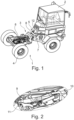
- Fig. 1 shows a base vehicle 1 for a swap body according to the invention with driver's cabin 2, vehicle frame or chassis 3 and wheels 4.
- the base vehicle 1 has an articulated steering 5 in the embodiment shown, ie the chassis 3 consists of two chassis parts 6, 7, which are connected via an articulated joint 8.
- the base vehicle 1 can also have all other generally known types of steering such as axle steering, tank steering, rear-wheel, front-wheel or all-wheel steering, which in addition to wheels 4 also
- Chain drives and/or swing axles or the like For reasons of clarity and streamlining, a more detailed description and further explanations of other types of steering and chain drives have been omitted.
- tensioning cylinder 9 in the middle of the rear chassis section 6, which carries a tensioning wedge 10 at the front and is attached to the chassis at the rear via a bolt 11.
- An operating button 12 is attached to the front chassis section 7 in order to operate the tensioning cylinder outside the driver's cab 2.
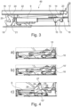
- Fig. 3 the clamping wedge 10 attached to the piston rod with its clamping surface 13, which runs downwards from front to back, is easier to see.
- the clamping wedge 10 is flat on its upper side 14 and slides along clamping plates 15. With the clamping surface 13, the clamping wedge 10 clamps a front locking bolt 16 downwards, which belongs to a swap body and locks it to the chassis 3 of the base vehicle 1.
- FIG. 3 a receiving claw 17 with two guide surfaces 18, 19 running towards each other from the back to the front is shown behind the clamping cylinder 9.
- two receiving claws 17 and two locking bolts 21 are advantageously present, which can be arranged on both sides or on the left and right of a frame 22 and/or the chassis 3.
- These two receiving claws 17 are preferably firmly attached to the chassis 3 and have a receiving opening 20 at the rear, through which a rear locking bolt 21 of the swap body is received in the respective receiving claw 17 and can be locked or clamped there.
- a frame 22 with front and rear tabs 23, 24 for fastening the front and rear locking bolts 16, 21 is shown in this illustration.
- FIG. 4 three representations a, b, c with different positions 10, 10', 10" of the clamping wedge 10 can be seen.
- the clamping wedge 10 clamps the front locking bolt 16 of a swap body.
- the middle representation b the clamping is released so that the locking bolt 16 is free.
- the clamping cylinder 9 In the position of the lower illustration c, the clamping cylinder 9 is completely retracted and a toggle lever 25, consisting of two individual levers 26, which are connected to a joint 28, is raised, whereby the toggle lever 25 or the front individual lever 26 also has a front face 27.
- the front individual lever 26 is driven along when the clamping cylinder 9 is retracted via a slotted guide (not shown in detail), which provides the toggle lever 25 with freewheeling when moving between the positions in illustrations a and b.
- the front locking bolt 16 In illustration c, the front locking bolt 16 is no longer shown, which corresponds to a removed interchangeable structure.
- the front face 27 of the front individual lever 26 can be seen in the Figure 4c ) advantageously form a support or a contact surface for an interchangeable body and thus a point of attack of the lifting unit formed by the toggle lever 25 on the interchangeable body.
- the joint 28 can have, for example, two rollers arranged on both sides (without further illustration), which form the support or contact surfaces for the interchangeable body and thus the Form the point of attack of the lifting unit formed by the knee lever 25 on the swap body, so that the swap body can advantageously roll and/or rest on/at these advantageous rollers.
- FIG. 5 An advantageous centering bolt 21 is shown, which is mounted on the swap body.
- the centering bolt 41 extends along the longitudinal axis of the swap body and is received on both sides by two stops 42, which are attached to the vehicle and in which Figure 5 only one of the stops 17 is shown.
- the stops 42 on both sides of the vehicle frame prevent it from slipping sideways.
- the centering bolt serves as a trigger for a sensor 29 for detecting the locked position.
- a locking button 29 serves as the sensor 29 for detecting the locked position of a swap body and thus for detecting whether the base vehicle is with or without a body.
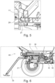
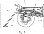
- FIG. 6 to 8 is a swap body in the form of a trough body 30 partially, in the Fig. 9 and 9 shown in perspective view.
- a tipping cylinder 31 is part of the swap body 30 and enables the tipping of a trough 32 of the trough body 30.
- the Figures 6 to 10 serve to illustrate the installation and removal of the trough body 30 on the base vehicle 1.
- the lifting of the body and its locking is carried out with the hydraulically operated tensioning cylinder 9.
- the driver can switch between a driving mode and a changeover mode using a switch in the cabin.
- the tensioning cylinder is hydraulically re-tensioned within a
- the control button 12 is deactivated in driving mode.
- change mode the base vehicle 1 can no longer be maneuvered.
- the automatic re-tensioning is deactivated and the button 12 is activated.
- the clamping cylinder 9 In driving mode, the clamping cylinder 9 is subjected to pressure. This clamps the clamping wedge 10 between the clamping plates 15 and the front locking bolt 16.
- the wedge shape creates a force on the swap body 30 in the negative z-direction, i.e. downwards, which also pushes the swap body 30 forwards in the X-direction.
- the swap body is therefore clamped without play between two receiving claws 17 on both sides and the clamping wedge 10. If the locking bolts 16, 21, the receiving claws 17 or the clamping wedge 10 become loose over time, the entire system remains free of play because the clamping cylinder is under pressure and is automatically re-tightened.
- the rear supports 33 are attached to the swap body 30, for example, pushed into a holder not shown in detail or folded out from the swap body if they are arranged directly on the swap body.
- the operating button 12 is then operated in the change mode, whereby the clamping cylinder 9 is retracted.
- the clamping wedge 10 initially releases the front locking bolt 16.
- the freewheel of the toggle lever 25 has been completed, it is taken along by the clamping cylinder 9 and the change body 30 is raised, which is particularly important in Fig. 8
- front supports 34 are attached to the Interchangeable body 30 is attached, for example inserted into a holder not shown in detail. This situation is in Fig. 9 shown.
- the supports 33, 34 are carried on the base vehicle 1 and/or on the swap body 30, e.g. with a fixing mechanism such as a latch etc. and/or in a storage space or drawer or the like (not shown in detail).
- a fixing mechanism such as a latch etc.
- this can also be achieved semi-automatically/automatically with a support drive, in particular with hydraulic and/or electrical actuators such as hydraulic cylinders or electric motors etc.
- the same can also be implemented with an optional length adjustment with fixing option either manually and/or semi-automatically/automatically.
- the swap body rests on its rear 33 and front 34 supports and the base vehicle 1 can be driven out from under the swap body 30 after activating the driving mode, as shown in Fig. 10 is recognizable.
- the loading of a swap body 30 is carried out in reverse order.
- the swap body 30 is placed on its supports 33, 34.
- the tensioning cylinder 9 is extended so far that the knee lever 25 is in the lowest position.
- the base vehicle 1 can now be driven under the swap body 30.
- the swap body can have side guide plates as well as front and rear stops (not shown in more detail). These side guide plates advantageously bring the swap body into the correct position in the lateral direction in relation to the base vehicle 1.
- the front and rear stops limit the entry depth of the base vehicle 1 and thus ensure the correct end position in the direction of reversing. Once the end position for receiving the swap body 30 has been reached, it can be picked up.
- the operator switches to the swap mode and then retracts the tensioning cylinder using the control button 12, thereby raising the swap body 30.
- the front supports 34 are now removed and the swap body is lowered by extending the tensioning cylinder 9 while simultaneously lowering the toggle lever 25.
- the swap body 30 is locked to the base vehicle 1 by the tensioning wedge 10 and the locking bolts 16,21.
- the tilting movement of the swap body 30 that begins when the toggle lever 25 is lowered relieves the load on the rear supports 33, which can then also be removed.
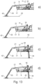
- FIG. 11a illustrates that the rear locking bolt 21 and the clamping wedge 10 have a distance A1, optional or advantageous attachment of the rear supports 33 to the swap body 30 or its support frame 49, unlocking, wherein the clamping wedge 10 moves with the aid of the drive 9 or hydraulic cylinder 9 along a freewheel 44 or slot 44 to the left along the arrow P, wherein in particular.
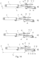
- Fig. 14a illustrates that a driver element 45 or bolt 45 is freely movable in the freewheel 44 or elongated hole 44, so that a carriage 46 or its base element 47 remains unadjusted or immobile.
- Fig. 11b) to 12b ) or Fig. 14a) to 14d The clamping wedge 10 moves with the help of the drive 9 or hydraulic cylinder 9 further along the freewheel 44 or slot 44 to the left along the arrow P until Fig. 12b ) or 14d) illustrate that the driver element 45 or the bolt 45 strikes the end of the freewheel 44 or the slot 44 and from now on is no longer movable therein, wherein the carriage 46 or its base element 47 remains unadjusted or immobile, wherein the corresponding two coupling elements 21, 10, 16 or the rear locking bolt 21 and the clamping wedge 10 or alternatively (not shown) to the front bolt 16 have a distance A2, wherein the distance A2 is smaller than the distance A1 by one of the (previous) stroke of the drive 9 or hydraulic cylinder 9, the swap body 30 or its support frame 49 is now unlocked.
- Fig. 12c or Fig. 15a ):
- the clamping wedge 10 or a piston rod of the drive 9 or cylinder 9 moves further along the arrow P, the driver element 45 or the bolt 45 attached to the freewheel 44 takes a base element 47 of a slide 46 with it, the slide 46 being connected to the toggle lever 25 by a joint 48 so that the toggle lever 25 can be rotated relative to the slide 46, the toggle lever 25 or its components partially lift off in the vertical direction H, in particular a front side 27 which is designed as a contact surface 27 and/or engagement element 27, the interchangeable structure 30 or its support frame 49 rotate about a rotation axis D1 with a first radius R1, the rear support or supports 33 are also rotated about the rotation axis D1 and lower downwards towards the floor 43, the support 33 optionally also having a length adjustment with Fixing possibility (not shown), eg clamped and/or locked, in order to be advantageously (roughly) adaptable to the height or the distance to the floor 43, ie that the wedge 10 had
- Fig. 12d or Fig. 15a ):
- the clamping wedge 10 or the piston rod of the drive 9 or cylinder 9 moves further along the arrow P, the driver element 45 or the bolt 45 attached to the freewheel 44 continues to take the base element 47 of the slide 46 with it, the floor supports 33 touch the floor 43 or are supported on the floor 43, so that the interchangeable structure 30 or its support frame 49 now rotate about a second axis of rotation D2 with a second radius R2, i.e.
- the bolt 21 is levered out of the holder 21 or lifts off in the vertical direction H, whereby optionally or as an advantageous alternative the skid 42 can also be designed without a free-swinging separate foot (see illustration) and whereby advantageously instead, for example, a firmly attached, in particular curved base plate of the skid 42 is arranged on the support 33, whereby this will also result in a rolling movement or a rotation about an existing axis of rotation D2 arranged on the floor 43, ie on the (curved) floor plate or its contact surface (not shown),
- the clamping wedge 10 or the piston rod of the drive 9 or cylinder 9 moves further along the arrow P, the driver element 45 or the bolt 45 attached to the freewheel 44 continues to take the base element 47 of the carriage 46 with it, ie the lifting mechanism lifts the structure to the end position.
- Fig. 13c) to 13d ) or Fig. 15c) to 15d ) or Fig. 9 The front supports 34 are inserted laterally or brought into support position, then the side supports 34 are brought/adjusted to the correct length and fixed, e.g. clamped and/or locked, then the tensioning cylinder 9 can move forward again, ie against the arrow P, whereby the structure 30 lowers (not shown in more detail) until the side supports 34 have full contact with the ground, from this point on the structure 30 can be described as parked, the base vehicle 1 can move away or drive away.
- the swap body 30 is picked up in the reverse order. Further details such as electrical contact protection or presence control of the swap body 30 and/or the locking etc. by means of sensors, switches 12 or actuators or the like are not explained in more detail here, but can be advantageously added or provided.
- Another great advantage of the swap system according to the invention is that there are no active or energy-consuming components on the swap body 30, so that the energy for swapping, ie uncoupling and coupling, or the drive can be realized not only together with a single drive, but also exclusively on the base vehicle. Accordingly, the hydraulic system and/or electric drive system of the base vehicle 1 can be used.
Landscapes
- Engineering & Computer Science (AREA)
- Transportation (AREA)
- Mechanical Engineering (AREA)
- Body Structure For Vehicles (AREA)
- Lock And Its Accessories (AREA)
- Vehicle Step Arrangements And Article Storage (AREA)
Applications Claiming Priority (1)
| Application Number | Priority Date | Filing Date | Title |
|---|---|---|---|
| DE102022101937.3A DE102022101937A1 (de) | 2022-01-27 | 2022-01-27 | Baufahrzeug |
Publications (2)
| Publication Number | Publication Date |
|---|---|
| EP4227155A1 EP4227155A1 (de) | 2023-08-16 |
| EP4227155B1 true EP4227155B1 (de) | 2024-10-30 |
Family
ID=84982109
Family Applications (1)
| Application Number | Title | Priority Date | Filing Date |
|---|---|---|---|
| EP23152012.3A Active EP4227155B1 (de) | 2022-01-27 | 2023-01-17 | Baufahrzeug mit einem basisfahrzeug und einem aufbau |
Country Status (5)
| Country | Link |
|---|---|
| US (1) | US12534010B2 (da) |
| EP (1) | EP4227155B1 (da) |
| DE (1) | DE102022101937A1 (da) |
| DK (1) | DK4227155T3 (da) |
| ES (1) | ES3000060T3 (da) |
Families Citing this family (1)
| Publication number | Priority date | Publication date | Assignee | Title |
|---|---|---|---|---|
| DE102022101937A1 (de) * | 2022-01-27 | 2023-07-27 | Wacker Neuson Linz Gmbh | Baufahrzeug |
Family Cites Families (27)
| Publication number | Priority date | Publication date | Assignee | Title |
|---|---|---|---|---|
| US3362552A (en) * | 1965-10-27 | 1968-01-09 | Thiele Inc | Combined dump and elevate truck chassis mechanism for changeable bodies |
| US3425576A (en) * | 1966-12-22 | 1969-02-04 | Pullman Inc | Detachable container-chassis system |
| GB1189341A (en) * | 1967-04-08 | 1970-04-22 | Dobson Ltd W E & F | Improvements in or relating to Transportable Load-Carrying Appliances |
| US3486652A (en) * | 1968-05-14 | 1969-12-30 | Edgar C Seward | Truck body and container lifting device |
| US3817413A (en) * | 1969-11-12 | 1974-06-18 | R Ham | Demountable load carrying bodies |
| FR2262747A1 (fr) * | 1974-03-01 | 1975-09-26 | Bennes Marrel | Dispositif de verouillage, notamment pour une potence de manutention montee sur un vehicule |
| DE3138824C2 (de) | 1981-09-30 | 1986-04-24 | Konrad Wiedemann GmbH & Co KG, 3002 Wedemark | Transportfahrzeug zur Aufnahme und zum Transport von Behältern od. dgl. |
| CA1190917A (en) * | 1982-08-03 | 1985-07-23 | David N. Whitehouse | Detachable platform for truck body or trailer |
| ATE90044T1 (de) | 1987-04-13 | 1993-06-15 | Faun Gmbh | Universalarbeitsfahrzeug. |
| US5562390A (en) | 1995-01-24 | 1996-10-08 | Mcneilus Truck And Manufacturing, Inc. | Detachable truck body and handling mechanism |
| US6582176B1 (en) * | 1998-01-26 | 2003-06-24 | Guido Lehner | Supporting member with alternating positions and its use |
| US6068440A (en) * | 1998-05-21 | 2000-05-30 | Marathon Equipment Company | Locking mechanism for roll-off hoist |
| DE29905528U1 (de) * | 1999-03-25 | 2000-08-31 | Franz Xaver Meiller Fahrzeug- und Maschinenfabrik - GmbH & Co KG, 80997 München | Verriegelungseinrichtung zur Sicherung eines Wechselbehälters auf dem Aufbau eines Abrollkipp-Fahrzeugs |
| AT407135B (de) | 1999-03-25 | 2000-12-27 | Ranner Dietrich | Schwerfahrzeug |
| KR20060093305A (ko) * | 2005-02-21 | 2006-08-24 | 가부시키가이샤 미즈호 | 컨테이너 탈착 차량 및 컨테이너 탈착 방법 |
| GB2440675B (en) | 2006-08-02 | 2011-06-29 | James Kelly | A road vehicle |
| DE202008016731U1 (de) | 2008-12-05 | 2009-02-26 | Karl Müller GmbH & Co. KG Fahrzeugwerk | Transportfahrzeug für Behälter |
| US9120416B2 (en) | 2011-11-15 | 2015-09-01 | Hitachi Construction Machinery Co., Ltd. | Conveyance vehicle |
| DE202012007089U1 (de) | 2012-07-17 | 2012-10-04 | Karl Müller GmbH & Co. KG Fahrzeugwerk | Transportfahrzeug für Behälter |
| EP3177482B1 (de) | 2014-08-07 | 2019-10-16 | Alfred Kärcher SE & Co. KG | Wechselvorrichtung für einen aufbau eines fahrzeugs, kombination aus fahrzeug, mindestens einem aufbau und wechselvorrichtung und verfahren zum wechseln eines aufbaus bei einem fahrzeug |
| US10173572B2 (en) * | 2014-09-04 | 2019-01-08 | Mac Trailer Manufacturing, Inc. | Roll off trailer frame and two trolley assemblies |
| DE202016100964U1 (de) | 2016-02-24 | 2017-05-26 | Wacker Neuson Linz Gmbh | Arbeitsfahrzeug mit drehbarem Fahrersitz |
| DE102018133570A1 (de) | 2018-12-21 | 2020-06-25 | Sensata Technologies, Inc. | Verfahren zur Überwachung eines Ladungsträgerfahrzeugs, Überwachungsvorrichtung für ein Ladungsträgerfahrzeug, Ladungsträgerfahrzeug, Ladungsträgersystem und Wechselaufbau |
| DE102019102818B4 (de) | 2019-02-05 | 2021-11-11 | Rheinmetall Landsysteme Gmbh | Modulare Plattform |
| EP4107055A4 (en) * | 2020-02-18 | 2024-03-13 | Jagano Pty Ltd | SCOOP SYSTEM FOR A VEHICLE TUB |
| DE102020117247A1 (de) | 2020-06-30 | 2021-12-30 | Probst Gmbh | Wechselaufbau für ein Fahrgestell |
| DE102022101937A1 (de) * | 2022-01-27 | 2023-07-27 | Wacker Neuson Linz Gmbh | Baufahrzeug |
-
2022
- 2022-01-27 DE DE102022101937.3A patent/DE102022101937A1/de active Pending
-
2023
- 2023-01-17 EP EP23152012.3A patent/EP4227155B1/de active Active
- 2023-01-17 DK DK23152012.3T patent/DK4227155T3/da active
- 2023-01-17 ES ES23152012T patent/ES3000060T3/es active Active
- 2023-01-26 US US18/101,921 patent/US12534010B2/en active Active
Also Published As
| Publication number | Publication date |
|---|---|
| EP4227155A1 (de) | 2023-08-16 |
| ES3000060T3 (en) | 2025-02-27 |
| DK4227155T3 (da) | 2024-12-09 |
| US20230234492A1 (en) | 2023-07-27 |
| US12534010B2 (en) | 2026-01-27 |
| DE102022101937A1 (de) | 2023-07-27 |
Similar Documents
| Publication | Publication Date | Title |
|---|---|---|
| EP0023372B1 (de) | Verfahren zum Be- und Entladen von Eisenbahn-Tiefladewaggons mit Lastwagen - Sattelaufliegern sowie Tiefladewaggon hierfür | |
| DE69431516T2 (de) | Fahrzeug mit einem u-förmigen rahmen | |
| EP3268257B1 (de) | Hebbare tragvorrichtung | |
| DE69506569T2 (de) | Sattelauflieger, insbesondere zum transport von fahrzeugen und verfahren für sein verladen auf fahrzeuge und sein entladen von fahrzeugen | |
| DE60105062T2 (de) | Eisenbahneinheit mit schwenklagerkonstruktion zum kombinierten schienen/strassen-transport entweder eines sattelaufliegers oder von zwei motorfahrzeugen | |
| EP1661755B1 (de) | Lastentransportfahrzeug, insbesondere Absetzkipper | |
| DE1921477A1 (de) | Einrichtung zum Verbinden eines Ladegestells mit einer Sattelzugmaschine | |
| EP4227155B1 (de) | Baufahrzeug mit einem basisfahrzeug und einem aufbau | |
| DE3708066A1 (de) | Nutzfahrzeug mit wechselaufbau | |
| EP0490366A1 (de) | Transportfahrzeug mit Wechselaufbau | |
| EP0198042B1 (de) | Einachsanhänger | |
| DE3114500A1 (de) | "bergungs- und transportfahrzeug" | |
| EP4136001A1 (de) | Hubvorrichtung zur schienengeführten fortbewegung eines fahrzeugs | |
| DE68902098T2 (de) | Radunterlegkeil. | |
| EP2113413B1 (de) | Fahrzeugchassis für insbesondere Container, Aufbauten und dergleichen Ladungsbehälter | |
| AT520569A1 (de) | Verladevorrichtung | |
| EP3623218B1 (de) | Schlitten für ein transportfahrzeug zum transportieren von rollbehältern | |
| DE4232071C2 (de) | Fahrgestell, insbesondere für einen Anhänger | |
| DE102022107116A1 (de) | Fahrzeug mit einem Vorderwagenmodul, mit wenigstens einem Hinterwagenmodul und mit wenigstens einem Transportmodul | |
| DE3049507C2 (de) | Transportfahrzeug mit einem Fahrgestell mit Wechselvorrichtung und einem darauf absenkbaren Wechselaufbau | |
| DE202026100710U1 (de) | Tragrahmen für einen Wechselaufbau sowie Baufahrzeug | |
| DE68910673T2 (de) | Strassenschlepper für Containertransport. | |
| DE102008060734B3 (de) | Ladestütze für einen Sattelauflieger | |
| EP3623214B1 (de) | Nutzfahrzeug mit absenkbarem ladeboden | |
| EP0176102B1 (de) | Transportgestell, insbesondere für Flachglas-Stapel |
Legal Events
| Date | Code | Title | Description |
|---|---|---|---|
| PUAI | Public reference made under article 153(3) epc to a published international application that has entered the european phase |
Free format text: ORIGINAL CODE: 0009012 |
|
| STAA | Information on the status of an ep patent application or granted ep patent |
Free format text: STATUS: THE APPLICATION HAS BEEN PUBLISHED |
|
| AK | Designated contracting states |
Kind code of ref document: A1 Designated state(s): AL AT BE BG CH CY CZ DE DK EE ES FI FR GB GR HR HU IE IS IT LI LT LU LV MC ME MK MT NL NO PL PT RO RS SE SI SK SM TR |
|
| STAA | Information on the status of an ep patent application or granted ep patent |
Free format text: STATUS: REQUEST FOR EXAMINATION WAS MADE |
|
| 17P | Request for examination filed |
Effective date: 20240123 |
|
| RBV | Designated contracting states (corrected) |
Designated state(s): AL AT BE BG CH CY CZ DE DK EE ES FI FR GB GR HR HU IE IS IT LI LT LU LV MC ME MK MT NL NO PL PT RO RS SE SI SK SM TR |
|
| GRAP | Despatch of communication of intention to grant a patent |
Free format text: ORIGINAL CODE: EPIDOSNIGR1 |
|
| STAA | Information on the status of an ep patent application or granted ep patent |
Free format text: STATUS: GRANT OF PATENT IS INTENDED |
|
| INTG | Intention to grant announced |
Effective date: 20240611 |
|
| GRAS | Grant fee paid |
Free format text: ORIGINAL CODE: EPIDOSNIGR3 |
|
| GRAA | (expected) grant |
Free format text: ORIGINAL CODE: 0009210 |
|
| STAA | Information on the status of an ep patent application or granted ep patent |
Free format text: STATUS: THE PATENT HAS BEEN GRANTED |
|
| AK | Designated contracting states |
Kind code of ref document: B1 Designated state(s): AL AT BE BG CH CY CZ DE DK EE ES FI FR GB GR HR HU IE IS IT LI LT LU LV MC ME MK MT NL NO PL PT RO RS SE SI SK SM TR |
|
| REG | Reference to a national code |
Ref country code: GB Ref legal event code: FG4D Free format text: NOT ENGLISH |
|
| REG | Reference to a national code |
Ref country code: CH Ref legal event code: EP |
|
| REG | Reference to a national code |
Ref country code: IE Ref legal event code: FG4D Free format text: LANGUAGE OF EP DOCUMENT: GERMAN |
|
| REG | Reference to a national code |
Ref country code: DE Ref legal event code: R096 Ref document number: 502023000237 Country of ref document: DE |
|
| REG | Reference to a national code |
Ref country code: DK Ref legal event code: T3 Effective date: 20241204 |
|
| REG | Reference to a national code |
Ref country code: LT Ref legal event code: MG9D |
|
| REG | Reference to a national code |
Ref country code: ES Ref legal event code: FG2A Ref document number: 3000060 Country of ref document: ES Kind code of ref document: T3 Effective date: 20250227 |
|
| REG | Reference to a national code |
Ref country code: NL Ref legal event code: MP Effective date: 20241030 |
|
| PG25 | Lapsed in a contracting state [announced via postgrant information from national office to epo] |
Ref country code: IS Free format text: LAPSE BECAUSE OF FAILURE TO SUBMIT A TRANSLATION OF THE DESCRIPTION OR TO PAY THE FEE WITHIN THE PRESCRIBED TIME-LIMIT Effective date: 20250228 Ref country code: HR Free format text: LAPSE BECAUSE OF FAILURE TO SUBMIT A TRANSLATION OF THE DESCRIPTION OR TO PAY THE FEE WITHIN THE PRESCRIBED TIME-LIMIT Effective date: 20241030 Ref country code: PT Free format text: LAPSE BECAUSE OF FAILURE TO SUBMIT A TRANSLATION OF THE DESCRIPTION OR TO PAY THE FEE WITHIN THE PRESCRIBED TIME-LIMIT Effective date: 20250228 |
|
| PG25 | Lapsed in a contracting state [announced via postgrant information from national office to epo] |
Ref country code: FI Free format text: LAPSE BECAUSE OF FAILURE TO SUBMIT A TRANSLATION OF THE DESCRIPTION OR TO PAY THE FEE WITHIN THE PRESCRIBED TIME-LIMIT Effective date: 20241030 Ref country code: NL Free format text: LAPSE BECAUSE OF FAILURE TO SUBMIT A TRANSLATION OF THE DESCRIPTION OR TO PAY THE FEE WITHIN THE PRESCRIBED TIME-LIMIT Effective date: 20241030 |
|
| PG25 | Lapsed in a contracting state [announced via postgrant information from national office to epo] |
Ref country code: BG Free format text: LAPSE BECAUSE OF FAILURE TO SUBMIT A TRANSLATION OF THE DESCRIPTION OR TO PAY THE FEE WITHIN THE PRESCRIBED TIME-LIMIT Effective date: 20241030 |
|
| PG25 | Lapsed in a contracting state [announced via postgrant information from national office to epo] |
Ref country code: NO Free format text: LAPSE BECAUSE OF FAILURE TO SUBMIT A TRANSLATION OF THE DESCRIPTION OR TO PAY THE FEE WITHIN THE PRESCRIBED TIME-LIMIT Effective date: 20250130 |
|
| PG25 | Lapsed in a contracting state [announced via postgrant information from national office to epo] |
Ref country code: LV Free format text: LAPSE BECAUSE OF FAILURE TO SUBMIT A TRANSLATION OF THE DESCRIPTION OR TO PAY THE FEE WITHIN THE PRESCRIBED TIME-LIMIT Effective date: 20241030 Ref country code: GR Free format text: LAPSE BECAUSE OF FAILURE TO SUBMIT A TRANSLATION OF THE DESCRIPTION OR TO PAY THE FEE WITHIN THE PRESCRIBED TIME-LIMIT Effective date: 20250131 |
|
| PG25 | Lapsed in a contracting state [announced via postgrant information from national office to epo] |
Ref country code: PL Free format text: LAPSE BECAUSE OF FAILURE TO SUBMIT A TRANSLATION OF THE DESCRIPTION OR TO PAY THE FEE WITHIN THE PRESCRIBED TIME-LIMIT Effective date: 20241030 |
|
| PG25 | Lapsed in a contracting state [announced via postgrant information from national office to epo] |
Ref country code: RS Free format text: LAPSE BECAUSE OF FAILURE TO SUBMIT A TRANSLATION OF THE DESCRIPTION OR TO PAY THE FEE WITHIN THE PRESCRIBED TIME-LIMIT Effective date: 20250130 |
|
| PG25 | Lapsed in a contracting state [announced via postgrant information from national office to epo] |
Ref country code: SM Free format text: LAPSE BECAUSE OF FAILURE TO SUBMIT A TRANSLATION OF THE DESCRIPTION OR TO PAY THE FEE WITHIN THE PRESCRIBED TIME-LIMIT Effective date: 20241030 |
|
| PG25 | Lapsed in a contracting state [announced via postgrant information from national office to epo] |
Ref country code: EE Free format text: LAPSE BECAUSE OF FAILURE TO SUBMIT A TRANSLATION OF THE DESCRIPTION OR TO PAY THE FEE WITHIN THE PRESCRIBED TIME-LIMIT Effective date: 20241030 |
|
| PG25 | Lapsed in a contracting state [announced via postgrant information from national office to epo] |
Ref country code: RO Free format text: LAPSE BECAUSE OF FAILURE TO SUBMIT A TRANSLATION OF THE DESCRIPTION OR TO PAY THE FEE WITHIN THE PRESCRIBED TIME-LIMIT Effective date: 20241030 |
|
| PG25 | Lapsed in a contracting state [announced via postgrant information from national office to epo] |
Ref country code: SK Free format text: LAPSE BECAUSE OF FAILURE TO SUBMIT A TRANSLATION OF THE DESCRIPTION OR TO PAY THE FEE WITHIN THE PRESCRIBED TIME-LIMIT Effective date: 20241030 |
|
| PG25 | Lapsed in a contracting state [announced via postgrant information from national office to epo] |
Ref country code: IT Free format text: LAPSE BECAUSE OF FAILURE TO SUBMIT A TRANSLATION OF THE DESCRIPTION OR TO PAY THE FEE WITHIN THE PRESCRIBED TIME-LIMIT Effective date: 20241030 |
|
| REG | Reference to a national code |
Ref country code: DE Ref legal event code: R097 Ref document number: 502023000237 Country of ref document: DE |
|
| PLBE | No opposition filed within time limit |
Free format text: ORIGINAL CODE: 0009261 |
|
| STAA | Information on the status of an ep patent application or granted ep patent |
Free format text: STATUS: NO OPPOSITION FILED WITHIN TIME LIMIT |
|
| PG25 | Lapsed in a contracting state [announced via postgrant information from national office to epo] |
Ref country code: SE Free format text: LAPSE BECAUSE OF FAILURE TO SUBMIT A TRANSLATION OF THE DESCRIPTION OR TO PAY THE FEE WITHIN THE PRESCRIBED TIME-LIMIT Effective date: 20241030 |
|
| PG25 | Lapsed in a contracting state [announced via postgrant information from national office to epo] |
Ref country code: LU Free format text: LAPSE BECAUSE OF NON-PAYMENT OF DUE FEES Effective date: 20250117 Ref country code: MC Free format text: LAPSE BECAUSE OF FAILURE TO SUBMIT A TRANSLATION OF THE DESCRIPTION OR TO PAY THE FEE WITHIN THE PRESCRIBED TIME-LIMIT Effective date: 20241030 |
|
| 26N | No opposition filed |
Effective date: 20250731 |
|
| PG25 | Lapsed in a contracting state [announced via postgrant information from national office to epo] |
Ref country code: BE Free format text: LAPSE BECAUSE OF NON-PAYMENT OF DUE FEES Effective date: 20250131 |
|
| REG | Reference to a national code |
Ref country code: BE Ref legal event code: MM Effective date: 20250131 |
|
| PG25 | Lapsed in a contracting state [announced via postgrant information from national office to epo] |
Ref country code: IE Free format text: LAPSE BECAUSE OF NON-PAYMENT OF DUE FEES Effective date: 20250117 |
|
| REG | Reference to a national code |
Ref country code: CH Ref legal event code: U11 Free format text: ST27 STATUS EVENT CODE: U-0-0-U10-U11 (AS PROVIDED BY THE NATIONAL OFFICE) Effective date: 20260201 |
|
| PGFP | Annual fee paid to national office [announced via postgrant information from national office to epo] |
Ref country code: ES Payment date: 20260217 Year of fee payment: 4 |
|
| PGFP | Annual fee paid to national office [announced via postgrant information from national office to epo] |
Ref country code: DK Payment date: 20260121 Year of fee payment: 4 Ref country code: DE Payment date: 20260120 Year of fee payment: 4 |
|
| PGFP | Annual fee paid to national office [announced via postgrant information from national office to epo] |
Ref country code: AT Payment date: 20260301 Year of fee payment: 4 |
|
| PGFP | Annual fee paid to national office [announced via postgrant information from national office to epo] |
Ref country code: FR Payment date: 20260128 Year of fee payment: 4 |
|
| PGFP | Annual fee paid to national office [announced via postgrant information from national office to epo] |
Ref country code: CZ Payment date: 20260106 Year of fee payment: 4 Ref country code: CH Payment date: 20260201 Year of fee payment: 4 |