EP4227201A1 - Dispositif de moteur et procédé de commande associé - Google Patents
Dispositif de moteur et procédé de commande associé Download PDFInfo
- Publication number
- EP4227201A1 EP4227201A1 EP22871065.3A EP22871065A EP4227201A1 EP 4227201 A1 EP4227201 A1 EP 4227201A1 EP 22871065 A EP22871065 A EP 22871065A EP 4227201 A1 EP4227201 A1 EP 4227201A1
- Authority
- EP
- European Patent Office
- Prior art keywords
- ring
- clutch
- electric machine
- clutch control
- driving
- Prior art date
- Legal status (The legal status is an assumption and is not a legal conclusion. Google has not performed a legal analysis and makes no representation as to the accuracy of the status listed.)
- Pending
Links
- 238000000034 method Methods 0.000 title claims abstract description 23
- 230000008602 contraction Effects 0.000 claims description 11
- 238000000926 separation method Methods 0.000 abstract description 2
- 238000010586 diagram Methods 0.000 description 14
Images




Classifications
-
- H—ELECTRICITY
- H02—GENERATION; CONVERSION OR DISTRIBUTION OF ELECTRIC POWER
- H02K—DYNAMO-ELECTRIC MACHINES
- H02K7/00—Arrangements for handling mechanical energy structurally associated with dynamo-electric machines, e.g. structural association with mechanical driving motors or auxiliary dynamo-electric machines
- H02K7/006—Structural association of a motor or generator with the drive train of a motor vehicle
-
- F—MECHANICAL ENGINEERING; LIGHTING; HEATING; WEAPONS; BLASTING
- F16—ENGINEERING ELEMENTS AND UNITS; GENERAL MEASURES FOR PRODUCING AND MAINTAINING EFFECTIVE FUNCTIONING OF MACHINES OR INSTALLATIONS; THERMAL INSULATION IN GENERAL
- F16D—COUPLINGS FOR TRANSMITTING ROTATION; CLUTCHES; BRAKES
- F16D11/00—Clutches in which the members have interengaging parts
-
- F—MECHANICAL ENGINEERING; LIGHTING; HEATING; WEAPONS; BLASTING
- F16—ENGINEERING ELEMENTS AND UNITS; GENERAL MEASURES FOR PRODUCING AND MAINTAINING EFFECTIVE FUNCTIONING OF MACHINES OR INSTALLATIONS; THERMAL INSULATION IN GENERAL
- F16D—COUPLINGS FOR TRANSMITTING ROTATION; CLUTCHES; BRAKES
- F16D11/00—Clutches in which the members have interengaging parts
- F16D11/14—Clutches in which the members have interengaging parts with clutching members movable only axially
-
- H—ELECTRICITY
- H02—GENERATION; CONVERSION OR DISTRIBUTION OF ELECTRIC POWER
- H02K—DYNAMO-ELECTRIC MACHINES
- H02K7/00—Arrangements for handling mechanical energy structurally associated with dynamo-electric machines, e.g. structural association with mechanical driving motors or auxiliary dynamo-electric machines
- H02K7/10—Structural association with clutches, brakes, gears, pulleys or mechanical starters
-
- H—ELECTRICITY
- H02—GENERATION; CONVERSION OR DISTRIBUTION OF ELECTRIC POWER
- H02K—DYNAMO-ELECTRIC MACHINES
- H02K7/00—Arrangements for handling mechanical energy structurally associated with dynamo-electric machines, e.g. structural association with mechanical driving motors or auxiliary dynamo-electric machines
- H02K7/10—Structural association with clutches, brakes, gears, pulleys or mechanical starters
- H02K7/116—Structural association with clutches, brakes, gears, pulleys or mechanical starters with gears
Definitions
- the present invention relates to the electromechanical field, in particular to an electric machine device and a control method thereof.
- the bicycles will still be subjected to the resistance of the gear and the clutch inside the electric machine when the existing brushless toothed electric machine clutch system is used while the electric machine is powered off, so that the rider cannot ride as easily as an ordinary bicycle.
- the present invention provides an electric machine device and a control method thereof.
- the electric machine device of the present invention comprises an electric machine shaft and an electric machine housing provided on the electric machine shaft, a motor set module is provided inside the electric machine housing, and a driving ring, a clutch ring and a clutch control module are provided on one end of the electric machine shaft extending from the output end of the motor set module; the clutch control module is used for controlling the engagement or disengagement of the driving ring and the clutch ring.
- the clutch control module specifically comprises a reset device, a clutch control ring and a clutch control switch; the clutch control ring and the reset device are provided between the driving ring and the clutch ring, and the clutch control switch is connected with the clutch control ring; the clutch control switch is able to drive the extension or contraction of the reset device by controlling the left and right rotation of the clutch control ring, so as to engage the driving ring and the clutch ring or disengage the driving ring from the clutch ring.
- one side of the driving ring engaged with the clutch ring is provided with dentate protrusions
- one side of the clutch ring engaged with the driving ring is provided with dentate protrusions matching with the dentate protrusions of the driving ring, and the dentate protrusions of the two are matched and engaged with each other in a case where the driving ring is engaged with the clutch ring.
- an electric machine cover and a clutch ring adapter ring are further comprised; the clutch ring adapter ring is provided inside the electric machine cover, and the clutch ring adapter ring is adapted to and connected with the clutch ring; the clutch control switch is provided above the electric machine cover, and can control the clutch ring adapter ring by means of the electric machine cover, so as to control the left and right rotation of the clutch control ring.
- the clutch control switch specifically is a clutch control knob.
- a scraper seal and a lock nut are further comprised; the clutch control knob is fixed and provided on the electric machine cover by means of the lock nut, and the scraper seal is provided between the clutch control knob and the lock nut.
- the clutch control module specifically comprises a reset device and a clutch control switch; the reset device is provided at one side of the clutch ring, and the clutch control switch is connected with the clutch ring; the clutch control switch is able to drive the clutch ring to be disengaged from the driving ring by pulling outward; the clutch ring is able to be engaged with the driving ring by means of the reset device.
- the clutch control switch specifically comprises a screw cap and a pull rod, the screw cap is provided at one end of the pull rod, and the other end of the pull rod is connected with the clutch ring; the screw cap is further provided with a positioning shaft and a positioning slot, and when the clutch control switch is pulled outward and drives the clutch ring to be disengaged from the driving ring, the clutch control switch is able to be fixed at a position by rotating the screw cap at a certain angle and clamping the positioning shaft into the positioning slot.
- the clutch control switch further comprises a fixing bolt, a bolt hole is provided on the pull rod, and the bolt hole is provided at one end connected with the clutch ring, and the fixing bolt is able to pass through the bolt hole, so that the clutch ring is fixed and linked with the pull rod.
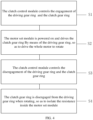
- the present invention further discloses a control method of an electric machine device, which comprises the following steps: a clutch control module controls the engagement of a driving ring and a clutch ring; the motor set module is powered on and drives the clutch ring by means of the driving ring, so as to drive the whole electric machine to rotate; the clutch control module controls the disengagement of the driving ring and the clutch ring; the clutch ring is disengaged from the driving ring when rotating, so as to isolate the resistance inside the motor set module.
- the step of the clutch control module controlling the engagement of the driving ring and the clutch ring and the clutch control module controlling the disengagement of the driving ring and the clutch ring specifically is the clutch control switch controls the left and right rotation of the clutch control ring to drive a contraction of the reset device, so that the driving ring is engaged with the clutch ring; the clutch control switch controls the left and right rotation of the clutch control ring to drive an extension of the reset device, so that the driving ring is disengaged from the clutch ring.
- an electric machine cover and a clutch ring adapter ring is further comprised, and the clutch control switch specifically is a clutch control knob; and the step of the clutch control switch controlling the left and right rotation of the clutch control ring to drive the contraction of the reset device, so that the driving ring is engaged with the clutch ring, and the clutch control switch controlling the left and right rotation of the clutch control ring to drive the extension of the reset device, so that the driving ring is disengaged from the clutch ring specifically comprises: rotating the clutch control knob, and the clutch control knob controls the clutch ring adapter ring by means of the electric machine cover and controls the left and right rotation of the clutch control ring, so as to drive the contraction of the reset device to engage the driving ring and the clutch ring; rotating the clutch control knob, and the clutch control knob controls the clutch ring adapter ring by means of the electric machine cover and controls the left and right rotation of the clutch control ring, so as to drive the extension of the reset device to disengage the driving ring from the clutch ring.
- the step of the clutch control module controlling the engagement of the driving ring and the clutch ring and the clutch control module controlling the disengagement of the driving ring and the clutch ring specifically is: pulling the clutch control switch outward and driving the clutch ring to be disengaged from the driving ring, meanwhile making the reset device contract due to the acting force pulling outward; in a case where the acting force pulling the clutch control switch outward is cancelled, the reset device extends to an original position to drive the engagement of the clutch ring and the driving ring.
- the electric machine device and the control method thereof according to the present invention can realize the cooperation and separation of electric machine assistance by adding another clutch system to the existing electric machine clutch system, it can realize the electric assistance of the electric machine to the bicycle when the electric machine is powered on, and when the electric machine is powered off, the bicycle wheels are not subjected to the resistance inside the electric machine device when the rider is riding naturally by a method of controlling the complete disengagement of the driving ring and the clutch ring inside the electric machine device, so as to make the riding easier and more labor-saving.
- FIG. 1 is a first structural schematic diagram of the electric machine device of the present invention
- FIG. 2 is a second structural schematic diagram of the electric machine device of the present invention.
- An electric machine device 1 according to the present invention includes an electric machine shaft 3 and an electric machine housing 2 provided on the electric machine shaft, a motor set module 21 is provided inside the electric machine housing 2.
- the electric machine device 1 can be installed on the front wheels and the rear wheels, and the electric machine shaft penetrates through the electric machine housing 1.
- a driving ring 4, a clutch ring 5 and a clutch control module are provided at one side of an output end of the motor set module 21.
- the driving ring 4, the clutch ring 5 and the clutch control module are specifically provided on one end of the electric machine shaft 3 extending from the output end of the motor set module 21.
- the clutch control module is use for controlling the engagement or disengagement of the driving ring 4 and the clutch ring 5.
- the clutch control module specifically comprises a reset device 6, a clutch control ring 7 and a clutch control switch 10.
- the clutch control ring 7 and the reset device 6 are provided between the driving ring 4 and the clutch ring 5, and the clutch control switch 10 is connected with the clutch control ring 7.
- the clutch control switch 10 is able to drive the extension or contraction of the reset device 6 by controlling the left and right rotation of the clutch control ring 7, so as to engage the driving ring 4 and the clutch ring 5 or disengage the driving ring 4 from the clutch ring 5.
- bearings are further comprised, the bearings are provided at the connections of the electric machine shaft 3 with the driving ring 4 and the clutch control ring 7.
- the electric machine device further comprises an electric machine cover 9, a clutch ring adapter ring 8, a scraper seal 11 and a lock nut 13.
- the clutch ring adapter ring 8 is provided inside the electric machine cover 9, and the clutch ring adapter ring 8 is adapted to and connected with the clutch ring 5.
- the clutch control switch 10 is provided on the electric machine cover 9, and is able to control the clutch ring adapter ring 8 by means of the electric machine cover 9, so as to control the left and right rotation of the clutch control ring 7.
- the electric machine cover 9 is connected with the electric machine housing 2 by means of a plurality of electric machine cover lock bolts, and the clutch control switch 10 is fixed and provided on the electric machine cover 9 by means of the lock nut, and the scraper seal 11 is provided between the clutch control switch 10 and the lock nut 13.
- a lock gasket 12 is provided under the lock nut 13.
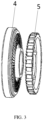
- FIG. 3 is a structural schematic diagram of the driving ring 4 and the clutch ring 5 of the present invention.
- one side of the driving ring 4 engaged with the clutch ring 5 is provided with dentate protrusions
- one side of the clutch ring 5 engaged with the driving ring 4 is provided with dentate protrusions matching with the dentate protrusions of the driving ring 4, and the dentate protrusions of the two are matched and engaged with each other when the driving ring is engaged with the clutch ring.
- FIG. 4 is a first schematic flowchart of the control method of the electric machine device of the present invention, the present invention further discloses the control method of the electric machine device, and the method specifically comprises the following steps:
- FIG. 5 is a second schematic flowchart of the control method of the electric machine device of the present invention, and the method specifically comprises the following steps:
- the specific structure of the electric machine device comprises an electric machine shaft and an electric machine housing provided on the electric machine shaft, the motor set module is provided inside the electric machine housing, and the electric machine device is installed on the front wheel of a bicycle, and the electric machine shaft penetrates through the electric machine housing.
- a driving ring, a clutch ring and a clutch control module are provided at one end of the electric machine shaft extending from the output end of the motor set module, and the clutch control module specifically comprises a reset device, a clutch control ring and a clutch control switch, the clutch control switch specifically is a clutch control knob, and the reset device specifically is a reset spring.
- the electric machine device further comprises an electric machine cover, a clutch ring adapter ring, a scraper seal and a lock nut.
- the clutch ring adapter ring is provided inside the electric machine cover, and the clutch ring adapter ring is adapted to and connected with the clutch ring.
- the clutch control knob is provided on the electric machine cover, and a user can manually rotate the clutch control knob, so as to control the clutch ring adapter ring by means of the electric machine cover, and thereby controlling the left and right rotation of the clutch control ring.
- the electric machine cover is connected with the electric machine housing by means of a plurality of electric machine cover lock bolts, and the clutch control knob is fixed and provided on the electric machine cover by means of the lock nut, and the scraper seal is provided between the clutch control switch and the lock nut, and a lock gasket is further provided under the lock nut.
- the clutch control knob controls the clutch ring adapter ring by means of the electric machine cover and controls the left and right rotation of the clutch control ring, so as to drive the extension of the reset device to disengage the driving ring from the clutch ring.
- the clutch ring is disengaged from the driving ring when rotating, so as to isolate the resistance inside the motor set module.
- a gear set is provided inside the motor set module, and the gear set is connected with the electric machine shaft.
- the specific structure of the electric machine device includes an electric machine shaft and an electric machine housing provided on the electric machine shaft, the motor set module is provided inside the electric machine housing, and the electric machine device is installed on the front wheel of the bicycle, and the electric machine shaft is designed not to penetrate through the electric machine housing.
- a driving ring, a clutch ring and a clutch control module are provided on one end of the electric machine shaft extending from the output end of the motor set module, and the clutch control module specifically comprises a reset device, a clutch control ring and a clutch control switch, the reset device specifically is a reset spring;
- the electric machine device further comprises an electric machine cover, a clutch ring adapter ring, a scraper seal and a lock nut.
- the clutch ring adapter ring is provided inside the electric machine cover, and the clutch ring adapter ring is adapted to and connected with the clutch ring.
- the clutch control switch specifically is an electric clutch control switch, and further comprises a control module; the control module is electrically connected with the electric clutch control switch and the clutch ring adapter ring. By pressing the electric clutch control switch, the control module can be driven to control the clutch ring adapter ring, so as to control the left and right rotation of the clutch control ring.
- the electric machine cover is connected with the electric machine housing by means of a plurality of electric machine cover lock bolts, and the clutch control knob is fixed and provided on the electric machine cover by means of the lock nut, and the scraper seal is provided between the clutch control switch and the lock nut, and the lock gasket is further provided under the lock nut.
- FIG. 6 is a first structural schematic diagram of the third embodiment of the present invention
- FIG. 7 is a second structural schematic diagram of the third embodiment of the present invention
- FIG. 8 is a third structural schematic diagram of the third embodiment of the present invention
- FIG. 9 is a fourth structural schematic diagram of the third embodiment of the present invention.
- the electric machine device 1 specifically comprises an electric machine shaft 3 and an electric machine housing provided on the electric machine shaft, a motor set module is provided inside the electric machine housing, and a driving ring 4, a clutch ring 5 and a clutch control module are provided at one side of the output end of the motor set module; the clutch control module specifically comprises a reset device 6' and a clutch control switch.
- the reset device specifically is a spring 6', which is provided at one side of the clutch ring between the clutch ring 5 and the electric machine cover 9
- the clutch control switch specifically comprises a screw cap 10', a pull rod 101' and a fixing bolt 103', the screw cap 10' is provided at one end of the pull rod 101', and the other end of the pull rod 101' is fixed and connected with the clutch ring 5; the screw cap 10' is further provided with a positioning shaft and a positioning slot, the pull rod is provided with a bolt hole 102', and the bolt hole 102' is provided at one end connected with the clutch ring 5, and the fixing bolt is able to pass through the bolt hole 102', so that the clutch ring 5 is fixed and linked with the pull rod 101'; the length of the fixing bolt 103' is larger than the diameter of the inner hole of the clutch ring 5, so that the clutch ring 5 can be clamped on the pull rod 101' after the fixing bolt 103' is inserted into the bolt hole 102'.
- the position of the spring 6' can also be provided between the clutch ring 5 and the driving ring 4.
- the spring 6' provided between the clutch ring 5 and the electric machine housing can also be driven to extend, and when the user wants to restore the engagement of the clutch ring 5 and the driving ring 4, the clutch control switch can be slightly released.
- the spring 6' which is in an extended state is able to pull the clutch ring 5 back to its original position under the retracting force, so as to achieve the purpose of engaging the clutch ring 5 with the driving ring 4 again.
Landscapes
- Engineering & Computer Science (AREA)
- Power Engineering (AREA)
- General Engineering & Computer Science (AREA)
- Mechanical Engineering (AREA)
- Connection Of Motors, Electrical Generators, Mechanical Devices, And The Like (AREA)
- Electric Propulsion And Braking For Vehicles (AREA)
Applications Claiming Priority (2)
| Application Number | Priority Date | Filing Date | Title |
|---|---|---|---|
| CN202111634711.0A CN114110034A (zh) | 2021-12-29 | 2021-12-29 | 一种电机装置及其控制方法 |
| PCT/CN2022/131897 WO2023124591A1 (fr) | 2021-12-29 | 2022-11-15 | Dispositif de moteur et procédé de commande associé |
Publications (3)
| Publication Number | Publication Date |
|---|---|
| EP4227201A1 true EP4227201A1 (fr) | 2023-08-16 |
| EP4227201A8 EP4227201A8 (fr) | 2023-10-11 |
| EP4227201A4 EP4227201A4 (fr) | 2024-11-06 |
Family
ID=80363306
Family Applications (1)
| Application Number | Title | Priority Date | Filing Date |
|---|---|---|---|
| EP22871065.3A Pending EP4227201A4 (fr) | 2021-12-29 | 2022-11-15 | Dispositif de moteur et procédé de commande associé |
Country Status (3)
| Country | Link |
|---|---|
| EP (1) | EP4227201A4 (fr) |
| CN (2) | CN114110034A (fr) |
| WO (1) | WO2023124591A1 (fr) |
Cited By (1)
| Publication number | Priority date | Publication date | Assignee | Title |
|---|---|---|---|---|
| US20240263676A1 (en) * | 2023-02-08 | 2024-08-08 | Illinois Tool Works Inc. | Clutch |
Families Citing this family (2)
| Publication number | Priority date | Publication date | Assignee | Title |
|---|---|---|---|---|
| CN114110034A (zh) * | 2021-12-29 | 2022-03-01 | 无限联盟有限公司 | 一种电机装置及其控制方法 |
| TWI845314B (zh) * | 2023-05-22 | 2024-06-11 | 達詳科技股份有限公司 | 自行車的馬達傳動裝置 |
Family Cites Families (17)
| Publication number | Priority date | Publication date | Assignee | Title |
|---|---|---|---|---|
| CN2175489Y (zh) * | 1992-11-07 | 1994-08-24 | 张伯强 | 自行车轮毂发电机 |
| US7686145B2 (en) * | 2005-09-21 | 2010-03-30 | Sanyo Electric Co., Ltd. | Drive device for electrically movable vehicles and electric wheelchair having same |
| KR101224144B1 (ko) * | 2009-10-20 | 2013-01-18 | 송강영 | 전기자전거의 동력전달기구 |
| CN204489089U (zh) * | 2015-03-04 | 2015-07-22 | 吴森泉 | 电动自行车的助力系统及电动自行车 |
| DE102015122918A1 (de) * | 2015-12-29 | 2017-06-29 | Chosen Co., Ltd. | Sperrradanordnung für eine Fahrradnabe |
| CN206922580U (zh) * | 2017-05-25 | 2018-01-23 | 盟立自动化科技(上海)有限公司 | 具有手动和电动离合装置的电动机 |
| JP2019006173A (ja) * | 2017-06-21 | 2019-01-17 | 株式会社ジェイテクト | 補助駆動装置 |
| WO2019167261A1 (fr) * | 2018-03-02 | 2019-09-06 | 本田技研工業株式会社 | Dispositif d'entraînement |
| CN208457060U (zh) * | 2018-05-24 | 2019-02-01 | 江苏雷利电机股份有限公司 | 离合装置和包括该离合装置的电机系统 |
| FR3088696B1 (fr) * | 2018-11-15 | 2020-11-06 | Mavic Sas | Dispositif d'assistance électrique pour vélo |
| CN109677560B (zh) * | 2018-12-31 | 2024-12-03 | 杭州速控软件有限公司 | 电动滑板车离合式驱动轮 |
| CN213442937U (zh) * | 2020-10-20 | 2021-06-15 | 广西迪锐乐运动器材有限公司 | 自行车助力装置、自行车助力系统及自行车 |
| CN113381549A (zh) * | 2020-12-14 | 2021-09-10 | 南通雷圣特种电机有限公司 | 一种新型变速轮毂电机 |
| CN112503108B (zh) * | 2020-12-31 | 2025-10-31 | 温岭市华鑫机械制造有限公司 | 中间轴离合机构 |
| CN214985883U (zh) * | 2021-05-31 | 2021-12-03 | 南京信息工程大学 | 一种离合式助力自行车 |
| CN217558819U (zh) * | 2021-12-29 | 2022-10-11 | 混合路径有限公司 | 一种电机装置 |
| CN114110034A (zh) * | 2021-12-29 | 2022-03-01 | 无限联盟有限公司 | 一种电机装置及其控制方法 |
-
2021
- 2021-12-29 CN CN202111634711.0A patent/CN114110034A/zh active Pending
-
2022
- 2022-11-15 CN CN202280006478.8A patent/CN116685779A/zh active Pending
- 2022-11-15 EP EP22871065.3A patent/EP4227201A4/fr active Pending
- 2022-11-15 WO PCT/CN2022/131897 patent/WO2023124591A1/fr not_active Ceased
Cited By (2)
| Publication number | Priority date | Publication date | Assignee | Title |
|---|---|---|---|---|
| US20240263676A1 (en) * | 2023-02-08 | 2024-08-08 | Illinois Tool Works Inc. | Clutch |
| US12379002B2 (en) * | 2023-02-08 | 2025-08-05 | Illinois Tool Works Inc. | Clutch |
Also Published As
| Publication number | Publication date |
|---|---|
| CN116685779A (zh) | 2023-09-01 |
| EP4227201A8 (fr) | 2023-10-11 |
| CN114110034A (zh) | 2022-03-01 |
| WO2023124591A1 (fr) | 2023-07-06 |
| EP4227201A4 (fr) | 2024-11-06 |
Similar Documents
| Publication | Publication Date | Title |
|---|---|---|
| EP4227201A1 (fr) | Dispositif de moteur et procédé de commande associé | |
| EP2122197B1 (fr) | Transmission pour moteur et son dispositif de commande | |
| JP7187339B2 (ja) | ブラインドナット締結装置 | |
| TWI793189B (zh) | 用於車輛之傳輸系統 | |
| CN101189094A (zh) | 用于带有动力输出和静止轴特征的工具夹盘的电子离合器 | |
| CN112109840A (zh) | 一种助力自行车的中置电机 | |
| CN205220977U (zh) | 电动自行车轮毂 | |
| EP3073620A1 (fr) | Moteur de moyeu de roue et son procédé d'utilisation | |
| US5895991A (en) | Electric generator for bicycles | |
| CN217558819U (zh) | 一种电机装置 | |
| CN222680782U (zh) | 一种多功能组合工具 | |
| CN222084992U (zh) | 一种用于助力自行车的电控离合器 | |
| WO2023236046A1 (fr) | Ensemble d'entraînement à assistance électrique | |
| CN212429696U (zh) | 边三轮摩托车的倒挡器 | |
| JP3983079B2 (ja) | 電動レンチ | |
| JP3490901B2 (ja) | 電動自転車 | |
| CN214241129U (zh) | 助力车 | |
| CN112803286B (zh) | 一种电气设备电缆端口绝缘堵帽装卸器及其使用方法 | |
| KR20130078846A (ko) | 전기 자전거의 구동장치 | |
| EP3480104A1 (fr) | Moteur d'entraînement à manivelle pour bicyclette électrique avec changement de vitesse automatique | |
| JP3015707U (ja) | 自転車用駆動装置 | |
| CN107366732B (zh) | 自动弹力变挡差速电机 | |
| CN222934051U (zh) | 中置电机和助力自行车 | |
| CN219487664U (zh) | 一种应用于助力车的飞轮结构 | |
| US20260116495A1 (en) | Device for a bicycle, bicycle, and method for operating a device for a bicycle |
Legal Events
| Date | Code | Title | Description |
|---|---|---|---|
| STAA | Information on the status of an ep patent application or granted ep patent |
Free format text: STATUS: UNKNOWN |
|
| STAA | Information on the status of an ep patent application or granted ep patent |
Free format text: STATUS: THE INTERNATIONAL PUBLICATION HAS BEEN MADE |
|
| PUAI | Public reference made under article 153(3) epc to a published international application that has entered the european phase |
Free format text: ORIGINAL CODE: 0009012 |
|
| STAA | Information on the status of an ep patent application or granted ep patent |
Free format text: STATUS: REQUEST FOR EXAMINATION WAS MADE |
|
| 17P | Request for examination filed |
Effective date: 20230329 |
|
| AK | Designated contracting states |
Kind code of ref document: A1 Designated state(s): AL AT BE BG CH CY CZ DE DK EE ES FI FR GB GR HR HU IE IS IT LI LT LU LV MC ME MK MT NL NO PL PT RO RS SE SI SK SM TR |
|
| RIN1 | Information on inventor provided before grant (corrected) |
Inventor name: TIAN, GANG Inventor name: GAO, SHUSAN |
|
| REG | Reference to a national code |
Ref country code: DE Ref legal event code: R079 Free format text: PREVIOUS MAIN CLASS: B62M0006550000 Ipc: H02K0007100000 |
|
| A4 | Supplementary search report drawn up and despatched |
Effective date: 20241004 |
|
| RIC1 | Information provided on ipc code assigned before grant |
Ipc: H02K 7/116 20060101ALI20240927BHEP Ipc: H02K 7/00 20060101ALI20240927BHEP Ipc: B62M 6/55 20100101ALI20240927BHEP Ipc: F16D 11/14 20060101ALI20240927BHEP Ipc: H02K 7/10 20060101AFI20240927BHEP |
|
| DAV | Request for validation of the european patent (deleted) | ||
| DAX | Request for extension of the european patent (deleted) |