EP4227227B1 - Bouteille de distribution à verrouillage automatique - Google Patents
Bouteille de distribution à verrouillage automatique Download PDFInfo
- Publication number
- EP4227227B1 EP4227227B1 EP22871064.6A EP22871064A EP4227227B1 EP 4227227 B1 EP4227227 B1 EP 4227227B1 EP 22871064 A EP22871064 A EP 22871064A EP 4227227 B1 EP4227227 B1 EP 4227227B1
- Authority
- EP
- European Patent Office
- Prior art keywords
- cap
- rotating
- adapter
- receiving
- self
- Prior art date
- Legal status (The legal status is an assumption and is not a legal conclusion. Google has not performed a legal analysis and makes no representation as to the accuracy of the status listed.)
- Active
Links
Images



Classifications
-
- B—PERFORMING OPERATIONS; TRANSPORTING
- B65—CONVEYING; PACKING; STORING; HANDLING THIN OR FILAMENTARY MATERIAL
- B65B—MACHINES, APPARATUS OR DEVICES FOR, OR METHODS OF, PACKAGING ARTICLES OR MATERIALS; UNPACKING
- B65B3/00—Packaging plastic material, semiliquids, liquids or mixed solids and liquids, in individual containers or receptacles, e.g. bags, sacks, boxes, cartons, cans, or jars
- B65B3/04—Methods of, or means for, filling the material into the containers or receptacles
- B65B3/06—Methods of, or means for, filling the material into the containers or receptacles by gravity flow
-
- B—PERFORMING OPERATIONS; TRANSPORTING
- B65—CONVEYING; PACKING; STORING; HANDLING THIN OR FILAMENTARY MATERIAL
- B65D—CONTAINERS FOR STORAGE OR TRANSPORT OF ARTICLES OR MATERIALS, e.g. BAGS, BARRELS, BOTTLES, BOXES, CANS, CARTONS, CRATES, DRUMS, JARS, TANKS, HOPPERS, FORWARDING CONTAINERS; ACCESSORIES, CLOSURES, OR FITTINGS THEREFOR; PACKAGING ELEMENTS; PACKAGES
- B65D47/00—Closures with filling and discharging, or with discharging, devices
- B65D47/04—Closures with discharging devices other than pumps
- B65D47/20—Closures with discharging devices other than pumps comprising hand-operated members for controlling discharge
- B65D47/26—Closures with discharging devices other than pumps comprising hand-operated members for controlling discharge with slide valves, i.e. valves that open and close a passageway by sliding over a port, e.g. formed with slidable spouts
- B65D47/261—Closures with discharging devices other than pumps comprising hand-operated members for controlling discharge with slide valves, i.e. valves that open and close a passageway by sliding over a port, e.g. formed with slidable spouts having a rotational or helicoidal movement
- B65D47/265—Closures with discharging devices other than pumps comprising hand-operated members for controlling discharge with slide valves, i.e. valves that open and close a passageway by sliding over a port, e.g. formed with slidable spouts having a rotational or helicoidal movement between planar parts
-
- B—PERFORMING OPERATIONS; TRANSPORTING
- B65—CONVEYING; PACKING; STORING; HANDLING THIN OR FILAMENTARY MATERIAL
- B65B—MACHINES, APPARATUS OR DEVICES FOR, OR METHODS OF, PACKAGING ARTICLES OR MATERIALS; UNPACKING
- B65B39/00—Nozzles, funnels or guides for introducing articles or materials into containers or wrappers
- B65B39/001—Nozzles, funnels or guides for introducing articles or materials into containers or wrappers with flow cut-off means, e.g. valves
- B65B39/003—Rotating means
-
- B—PERFORMING OPERATIONS; TRANSPORTING
- B65—CONVEYING; PACKING; STORING; HANDLING THIN OR FILAMENTARY MATERIAL
- B65D—CONTAINERS FOR STORAGE OR TRANSPORT OF ARTICLES OR MATERIALS, e.g. BAGS, BARRELS, BOTTLES, BOXES, CANS, CARTONS, CRATES, DRUMS, JARS, TANKS, HOPPERS, FORWARDING CONTAINERS; ACCESSORIES, CLOSURES, OR FITTINGS THEREFOR; PACKAGING ELEMENTS; PACKAGES
- B65D41/00—Caps, e.g. crown caps or crown seals, i.e. members having parts arranged for engagement with the external periphery of a neck or wall defining a pouring opening or discharge aperture; Protective cap-like covers for closure members, e.g. decorative covers of metal foil or paper
- B65D41/32—Caps or cap-like covers with lines of weakness, tearing-strips, tags, or like opening or removal devices, e.g. to facilitate formation of pouring openings
- B65D41/34—Threaded or like caps or cap-like covers provided with tamper elements formed in, or attached to, the closure skirt
Definitions
- the invention discloses a self-locking subpackaging bottle, and relates to the technical field of subpackaging of liquid or emulsion products.
- the invention provides a self-locking subpackaging bottle with a simple structure and a self-locking switch.
- a self-locking subpackaging bottle comprises a bottle body, a bottle cap and an adapter;
- the diameter of the outer wall of the receiving cap is greater than that of the rotating cap, which allows the rotating cap to easily extend downward into the inner wall of the rotating ring, and the receiving cap directly fits to the fixing ring above the rotating ring.
- the bottom of the inner wall of the annular cap is provided with an internal thread for connecting an empty bottle.
- the rotating ring comprises a handle, a first rotating sleeve, a connecting body and a second rotating sleeve, the first rotating sleeve and the second rotating sleeve are respectively connected to two sides of the connecting body, the handle is connected to the connecting body, the connecting body is connected to the first bearing through the second rotating sleeve, a notch is formed in the annular cap, the handle extends out of the adapter cap from the notch, and an initial end of the notch is L-shaped.
- an end, connected to the connecting body, of the handle is designed as an arc-shaped piece, the connecting body is connected to a limit screw, a round hole is formed in the arc-shaped piece, the diameter of the round hole is greater than that of the limit screw, and an elastic piece is arranged between the connecting body and the arc-shaped piece; two groups of elastic pieces are arranged at each end of the arc-shaped piece; and when the handle is located at the initial end of the notch, the outer elastic piece supports the arc-shaped piece upwards, and the inner elastic piece pulls the handle downwards and fits into a tail end of the L-shaped groove to limit the lateral position of the handle.
- a stopper is hinged to the outside of the adapter cap and comprises a connecting strip and a stopper strip, the middle of the connecting strip is hinged to the outside of the adapter cap, the stopper strip is arranged at one end of the connecting strip, and extends to the rotating ring through a stopper opening formed in the adapter cap, the connecting body of the rotating ring is provided with a recess matched with the stopper strip, and a reset spring is arranged between the stopper strip and the annular cap.
- the stopper strip is arranged in the diameter direction of the adapter cap, and the stopper strip is arranged at an end away from the adapter cap.
- a sealing gasket is arranged between the receiving cap and the rotating cap, the sealing gasket is provided with a through hole, the seal gasket is arranged at the bottom of the receiving cap, the through hole in the sealing gasket is aligned with the through hole in the receiving cap, and the through hole in the rotating cap is movable relative to the through hole in the receiving cap;
- the through hole comprises an air flow hole and a liquid flow hole; when the through hole in the rotating cap is misaligned with the through hole in the receiving cap, the bottle cap is closed; only when the rotating cap rotates and the inner through hole is aligned with the through hole in the receiving cap, can the bottle cap be in an open state; and the liquid flow hole is directly designed on the receiving cap, the air flow hole is connected to an air guide tube, and an air port at the other end of the air guide tube is at an air position of the inverted bottle body.
- the receiving cap is connected to the bottle body through an internal thread for fixing the bottle cap.
- An empty bottle is connected to a screw thread at the bottom of the adapter cap; when the empty bottle rotates and rises, a bottle body of the empty bottle touches the hinged stopper, and the position of the connecting strip on the side of the bottle body rises and the position on the side of the stopper strip falls. Therefore, the stopper strip is separated from a recess of the rotating ring, the rotating ring is unlocked, the handle is lifted to the transverse direction of the notch, the rotating ring is moved through the handle so as to drive the adapter cap to rotate, the through hole in the adapter cap is aligned with the through hole in the receiving cap, the bottle cap is opened, and then the product in the bottle body can flow into the empty bottle below through the liquid flow hole to achieve subpackaging.
- the handle After subpackaging, the handle is loosened to close the bottle cap, and the empty bottle is taken out; and under the action of the reset spring on the stopper, the stopper strip moves upward again to fit into the recess of the rotating ring, so as to realize self-locking of the handle.
- the invention has an extraordinarily structure, solves the problem that traditional subpackaging equipment occupies a large area, and allows subpackaging equipment to be used in stores to meet the customization requirement of customers and realize subpackaging experience of customers.
- the switch structure of the invention adopts a self-locking structure, and the self-locking switch is ingeniously designed with a handle and a stopper, the stopper is arranged at the bottom of the adapter cap and is protected against accidental touches, and the stopper strip can be separated from the handle only when the bottle body is screwed to the adapter cap, thus avoiding waste.
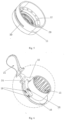
- a self-locking subpackaging bottle comprises a bottle body 1, a bottle cap 2 and an adapter 3.
- the bottle body 1 and the adapter 3 are arranged on a holder 28 in an inverted manner, the bottle body 1 is arranged inside the holder 28, the adapter 3 is fixedly connected to the holder, and the bottle body 1 is fixed by the holder 28 after being arranged in an inverted manner.
- the bottle cap 2 comprises a receiving cap 4 and a rotating cap 5, wherein the receiving cap 4 and the rotating cap 5 are sequentially arranged at a front end of the bottle body 1, a snap joint 6 is arranged between the receiving cap 4 and the rotating cap 5, and the rotating cap 5 is sleeved outside a front end of the receiving cap 4; through holes 7 are formed in the receiving cap 4 and the rotating cap 5, and the receiving cap 4 is connected to the bottle body 1 through an internal thread for fixing the bottle cap 2; and only when the through holes formed in the receiving cap 4 and the rotating cap 5 are aligned, can a product inside the bottle body 1 flow out.
- the product in this embodiment may be a liquid product such as perfume.
- the bottom of the inner wall of the annular cap 11 is provided with an internal thread for connecting an empty bottle 29.
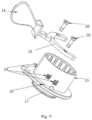
- the rotating ring 9 comprises a handle 14, a first rotating sleeve 15, a connecting body 16 and a second rotating sleeve 17, wherein the first rotating sleeve 15 and the second rotating sleeve 17 are respectively connected to two sides of the connecting body 16, the handle 14 is connected to the connecting body 16, and gear teeth are arranged inside the first rotating sleeve; the first rotating sleeve meshes with the outer wall of the rotating cap, the connecting body 16 is connected to the first bearing through the second rotating sleeve 17, the annular cap 11 is provided with a notch 30, and the handle 14 extends out of the adapter cap 8 from the notch 30; and the handle 14 drives the whole rotating ring 9 to rotate, and the rotating ring 9 drives the rotating cap 5 to rotate.
- the notch 30 can be designed as a quarter of an arc, which is matched with the through holes on the receiving cap 4 and the rotating cap 5 in a staggered manner, and the total angle of the two parts is designed as 90 degrees, that is, the bottle cap can be opened after the handle moves by the length of the notch.
- the angle between the through hole in the receiving cap and the through hole in the rotating cap can also be designed as other angles.
- An end, connected to the connecting body 16, of the handle 14 is designed as an arc-shaped piece 18, the connecting body 16 is connected to a limit screw 20, a round hole is formed in the arc-shaped piece 18, and the diameter of the round hole is greater than that of the limit screw 20; an elastic piece 19 is arranged between the connecting body 16 and the arc-shaped piece 18, two groups of elastic pieces 19 are respectively arranged at two ends of the arc-shaped piece, and the elastic pieces 19 are designed as springs; the inner elastic piece 19 is connected through a limit screw, and the outer elastic piece is connected through a connecting post; the limit screw 20 is sleeved in a spring, the limit screw 20 is similar to a fulcrum or can be understood as a rotating shaft, and the handle 14 can move up and down around this fulcrum; and an outer end of the arc-shaped piece 18 is supported by an outer spring, so that a handle 14 end of the arc-shaped piece 18 stays in a downward state, ensuring that the handle 14 falls into the other end of a
- a stopper 21 is hinged to the outside of the adapter cap 8 and comprises a connecting strip 22 and a stopper strip 23, the middle of the connecting strip 22 is hinged to the outside of the adapter cap 8, the stopper strip 23 is arranged at one end of the connecting strip 22, and extends to the rotating ring 9 through a stopper opening formed in the adapter cap 8, the connecting body 16 of the rotating ring 9 is provided with a recess 24 matched with the stopper strip 23, and a reset spring is arranged between the stopper strip 23 and the annular cap 11.
- the stopper strip 23 is arranged in the diameter direction of the adapter cap 8, and the stopper strip 23 is arranged at an end away from the adapter cap 8.
- a sealing gasket 25 is arranged between the receiving cap 4 and the rotating cap 5, the sealing gasket 25 is provided with a through hole 7, which is aligned with the through hole 7 on the receiving cap 4, and the through hole 7 on the rotating cap 5 is movable relative to the through hole 7 on the receiving cap 4;
- the through hole 7 comprises an air flow hole and a liquid flow hole; when the through hole 7 on the rotating cap 5 is misaligned with the through hole 7 on the receiving cap 4, the bottle cap 2 is closed; only when the rotating cap 5 rotates and the inner through hole 7 is aligned with the through hole 7 on the receiving cap 4, can the bottle cap 2 be in an open state;
- the liquid flow hole is directly designed in the receiving cap 4, a liquid guide tube 26 is arranged under the liquid flow hole, and a liquid outlet of the liquid guide tube 26 extends to the empty bottle 29 below; and the air flow hole is connected to an air guide tube 27, and an air port at the other end of the air guide tube 27 is at an air position of the inverted bottle body 1.
- the stopper strip is separated from a recess of the rotating ring, the rotating ring is unlocked and moved through the handle so as to drive the adapter cap to rotate, the through hole in the adapter cap is aligned with the through hole in the receiving cap, the bottle cap is opened, and then the product in the bottle body can flow into the empty bottle below through the liquid flow hole to achieve subpackaging.
- the handle is loosened to close the bottle cap, and the empty bottle is taken out; and under the action of the reset spring on the stopper, the stopper strip moves upward again to fit into the recess of the rotating ring, so as to realize self-locking of the handle.
- the invention has an extraordinar structure, solves the problem that traditional subpackaging equipment occupies a large area, and allows subpackaging equipment to be used in stores to meet the customization requirement of customers and realize subpackaging experience of customers.
- the switch structure of the invention adopts a self-locking structure, and the self-locking switch is ingeniously designed with a handle and a stopper, the stopper is arranged at the bottom of the adapter cap and is protected from accidental touches, and the stopper strip can be separated from the handle only when the bottle body is screwed to the adapter cap; further, the handle of the application fits downwards into an initial end of an L-shaped groove by pulling the elastic piece, which limits lateral displacement, realizes double self-locking and avoids waste.
Landscapes
- Engineering & Computer Science (AREA)
- Mechanical Engineering (AREA)
- Closures For Containers (AREA)
Claims (9)
- Bouteille de sous-emballage autobloquante, comprenant : un corps de bouteille (1), un bouchon de bouteille (2) et un adaptateur (3),
dans lequel :
le bouchon de la bouteille comprend un bouchon récepteur (4) et un bouchon rotatif (5), le bouchon récepteur et le bouchon rotatif sont disposés séquentiellement à une extrémité avant du corps de la bouteille, le bouchon rotatif est manchonné rotatif à l'extérieur d'une extrémité avant du bouchon récepteur, et le bouchon récepteur et le bouchon rotatif sont pourvus d'orificesde passage (7) ; caractérisé en ce que l'adaptateur comprend un capuchon d'adaptateur (8), une bague rotative (9) et une bague de fixation (10) qui sont reliées coaxialement, le capuchon d'adaptateur comprend un capuchon annulaire (11), un premier palier (13) et une bague de support (12), le premier palier est disposé sur une paroi intérieure du capuchon annulaire, la bague de support est disposée au-dessus du premier palier, la bague rotative est reliée de manière rotative à l'intérieur du capuchon annulaire par l'intermédiaire du premier palier, et la bague de fixation est reliée à l'intérieur du capuchon annulaire par l'intermédiaire de la bague de support ; et une paroi intérieure de l'anneau rotatif s'engrène avec une paroi extérieure du bouchon rotatif, et une paroi intérieure de l'anneau de fixation s'engrène avec une paroi extérieure du bouchon récepteur. - Bouteille de sous-emballage autobloquante selon la revendication 1, dans laquelle le diamètre de la paroi extérieure du bouchon récepteur est supérieur à celui du bouchon rotatif.
- Bouteille de sous-emballage autobloquante selon la revendication 1, dans laquelle un fond de la paroi intérieure du bouchon annulaire est pourvu d'un filetage interne.
- Bouteille de sous-emballage autobloquante selon la revendication 1, dans laquelle la bague rotative comprend une poignée (14), un premier manchon rotatif (15), un corpsde raccordement (16) et un second manchon rotatif (17), le premier manchon rotatif et le second manchon rotatif sont respectivement reliés à deux côtés du corps de raccordement, la poignée est reliée au corps de raccordement, le corps de raccordement est relié au premier palier par l'intermédiaire du second manchon rotatif, une encoche (30) est formée dans le capuchon annulaire, et la poignée s'étend hors du capuchon adaptateur à partir de l'encoche.
- Bouteille de sous-emballage autobloquante selon la revendication 1, dans laquelle une extrémité de la poignée, reliée au corps de raccordement, est conçue comme une pièce en forme d'arc (18), le corps de raccordement est relié à une vis de limitation (20), un trou rond est formé dans la pièce en forme d'arc, un diamètre du trou rond est supérieur àcelui de la vis de limitation, et une pièce élastique (19) est disposée entre le corpsde raccordement et la pièce en forme d'arc.
- La bouteille de sous-emballage autobloquante selon la revendication 1, dans laquelle un bouchon (21) est articulé à l'extérieur du bouchon adaptateur et comprend une bande de connexion (22) et une bande de bouchon (23), un milieu de la bande de connexion est articulé à l'extérieur du bouchon adaptateur, la bande de bouchon est disposée à une extrémité de la bande de connexion et s'étend jusqu'à la bague rotative à travers une ouverture de bouchon formée dans le bouchon adaptateur, la bande de butée est disposée à une extrémité de la bande de connexion et s'étend jusqu'à l'anneau rotatif à travers une ouverture de butée formée dans le capuchon d'adaptateur, une cavité (24) correspondant à la bande de butée est formée à l'extérieur de l'anneau rotatif, et un ressort de réinitialisation est disposé entre la bande de butée et le capuchon annulaire.
- Bouteille de sous-emballage autobloquante selon la revendication 6, dans laquelle la bande d'arrêt est disposée dans la direction du diamètre du bouchon adaptateur, et la bande d'arrêt est disposée à une extrémité éloignée du bouchon adaptateur.
- Bouteille de sous-emballage autobloquante selon la revendication 1, dans laquelle un joint d'étanchéité (25) est disposé entre le bouchon récepteur et le bouchon rotatif, le joint d'étanchéité est pourvu d'un trou de passage (7) qui est aligné avec le trou de passage du bouchon récepteur, le trou de passage du bouchon rotatif est mobile par rapport au trou de passage du bouchon récepteur, et le trou de passage comprend un trou d'écoulement d'air et un trou d'écoulement de liquide.
- Bouteille de sous-emballage autobloquante selon la revendication 1, dans laquelle le bouchon de réception est relié au corps de la bouteille par un filetage interne.
Applications Claiming Priority (2)
| Application Number | Priority Date | Filing Date | Title |
|---|---|---|---|
| CN202111662713.0A CN114379829B (zh) | 2021-12-31 | 2021-12-31 | 一种可自锁的分装瓶 |
| PCT/CN2022/094440 WO2023123832A1 (fr) | 2021-12-31 | 2022-05-23 | Bouteille de distribution à verrouillage automatique |
Publications (3)
| Publication Number | Publication Date |
|---|---|
| EP4227227A1 EP4227227A1 (fr) | 2023-08-16 |
| EP4227227A4 EP4227227A4 (fr) | 2024-05-15 |
| EP4227227B1 true EP4227227B1 (fr) | 2025-04-16 |
Family
ID=81199756
Family Applications (1)
| Application Number | Title | Priority Date | Filing Date |
|---|---|---|---|
| EP22871064.6A Active EP4227227B1 (fr) | 2021-12-31 | 2022-05-23 | Bouteille de distribution à verrouillage automatique |
Country Status (4)
| Country | Link |
|---|---|
| US (1) | US12325562B2 (fr) |
| EP (1) | EP4227227B1 (fr) |
| CN (1) | CN114379829B (fr) |
| WO (1) | WO2023123832A1 (fr) |
Families Citing this family (2)
| Publication number | Priority date | Publication date | Assignee | Title |
|---|---|---|---|---|
| CN114379829B (zh) | 2021-12-31 | 2025-08-01 | 迪亚姆展示设备(昆山)有限公司 | 一种可自锁的分装瓶 |
| CN116491753A (zh) * | 2023-05-11 | 2023-07-28 | 富瑞奥(东莞)实业有限公司 | 香水瓶转接装置以及用于该装置中的转接盖 |
Family Cites Families (22)
| Publication number | Priority date | Publication date | Assignee | Title |
|---|---|---|---|---|
| US6050309A (en) * | 1997-01-30 | 2000-04-18 | American Cyanamid Company | Valve assembly for use with containers in a closed application system |
| IT1292517B1 (it) * | 1997-05-29 | 1999-02-08 | Ruggero Borghetti | Tappo a chiusura automatica per bottiglie |
| KR200190169Y1 (ko) * | 1999-11-16 | 2000-07-15 | 차상문 | 덮개의 개폐가 편리하고 빨대가 부착된 마개 |
| US6612545B1 (en) * | 2000-04-12 | 2003-09-02 | David S. Smith Packaging Limited | Screw on connector |
| CN102233972B (zh) * | 2010-04-23 | 2013-06-19 | 宜昌华塑包装制品有限责任公司 | 防伪自锁瓶盖 |
| CN102233971B (zh) * | 2010-04-23 | 2013-06-19 | 宜昌华塑包装制品有限责任公司 | 防伪自锁限位瓶盖 |
| FR2972723B1 (fr) * | 2011-03-14 | 2013-03-15 | Techniplast | Dispositif de remplissage d'un flacon |
| TW201238851A (en) * | 2011-03-29 | 2012-10-01 | yao-zhang Liu | Bottle cap structure |
| FR3004707B1 (fr) * | 2013-04-17 | 2015-04-03 | Techniplast | Systeme de transvasement de liquide d'une recharge a un flacon a filetages internes etages |
| FR3021881B1 (fr) * | 2014-06-10 | 2018-03-09 | Lablabo | Dispositif de conditionnement et de distribution de produits pateux |
| FR3026393B1 (fr) * | 2014-09-30 | 2016-11-25 | Albea Le Treport | Flacon remplissable de distribution d’un produit fluide |
| BR112017023477B1 (pt) * | 2015-06-16 | 2021-10-05 | Amcor Group Gmbh | Fecho de conta-gotas resistente à criança |
| EP3162450A1 (fr) * | 2015-11-02 | 2017-05-03 | Albea Thomaston Inc. | Dispositif de distribution pour distribuer un produit liquide ou visqueux à partir d'un réservoir et réceptacle comprenant un tel dispositif de distribution |
| CN206010246U (zh) * | 2016-08-30 | 2017-03-15 | 无锡威孚力达催化净化器有限责任公司 | 定向移动旋转锁扣机构 |
| CN208115270U (zh) * | 2018-02-06 | 2018-11-20 | 珠海格力电器股份有限公司 | 一种瓶体组件及净水机 |
| CN208191792U (zh) * | 2018-05-24 | 2018-12-07 | 泉州市皆合纵五金制品有限公司 | 一种节能环保的宠物喂养设备 |
| IT201800006223A1 (it) * | 2018-06-12 | 2019-12-12 | Sistema erogatore a circuito chiuso | |
| WO2020160033A1 (fr) * | 2019-01-28 | 2020-08-06 | CW Consulting Associates, LLC | Appareil de marquage et kit pour alignement de monture en aveugle |
| CN210437703U (zh) * | 2019-03-11 | 2020-05-01 | 上海盖艺模塑科技有限公司 | 一种具有选择性自锁功能的瓶盖 |
| CN212408117U (zh) * | 2020-06-04 | 2021-01-26 | 深圳市华联盛世科技有限公司 | 一种一线通会议管理用显示装置 |
| CN114379829B (zh) * | 2021-12-31 | 2025-08-01 | 迪亚姆展示设备(昆山)有限公司 | 一种可自锁的分装瓶 |
| CN216916389U (zh) * | 2021-12-31 | 2022-07-08 | 迪亚姆展示设备(昆山)有限公司 | 一种可自锁的分装瓶 |
-
2021
- 2021-12-31 CN CN202111662713.0A patent/CN114379829B/zh active Active
-
2022
- 2022-05-23 US US18/037,774 patent/US12325562B2/en active Active
- 2022-05-23 WO PCT/CN2022/094440 patent/WO2023123832A1/fr not_active Ceased
- 2022-05-23 EP EP22871064.6A patent/EP4227227B1/fr active Active
Also Published As
| Publication number | Publication date |
|---|---|
| CN114379829A (zh) | 2022-04-22 |
| US12325562B2 (en) | 2025-06-10 |
| EP4227227A1 (fr) | 2023-08-16 |
| WO2023123832A1 (fr) | 2023-07-06 |
| US20240367873A1 (en) | 2024-11-07 |
| EP4227227A4 (fr) | 2024-05-15 |
| CN114379829B (zh) | 2025-08-01 |
Similar Documents
| Publication | Publication Date | Title |
|---|---|---|
| EP4227227B1 (fr) | Bouteille de distribution à verrouillage automatique | |
| US8657155B2 (en) | Single unit dispensing cap | |
| JP4316809B2 (ja) | コンテナ用密閉バルブ | |
| US4779773A (en) | Container cap with turnable retractable nozzle | |
| RU2010123018A (ru) | Повторно закрываемое открывное устройство для упаковок для текучих пищевых продуктов | |
| JP2007523668A5 (fr) | ||
| JPH01124561A (ja) | 計量機能を備えた容器閉鎖キャップ | |
| KR101383079B1 (ko) | 회전 액상 토출형 화장품 용기 | |
| US10723537B2 (en) | Cartridge pump | |
| US5292035A (en) | Reusable dispensing cap | |
| US20080110941A1 (en) | Rotational Dispensing Cap Closure for a Liquid Container | |
| US20100108724A1 (en) | Twist open/twist close Closure | |
| US2781152A (en) | Dispenser | |
| CN1249724A (zh) | 分配内装物的封闭件 | |
| US3406880A (en) | Dispensing closure cap | |
| RU67550U1 (ru) | Укупорочное устройство | |
| KR200448114Y1 (ko) | 방향성을 갖는 원터치 캡을 구비한 포장용기 | |
| US4684046A (en) | Unit dose liquid dispenser having precise dosage capabilities | |
| US7775400B2 (en) | Rotatable, reclosable closure | |
| US5044529A (en) | Liquid dispensing bottle cap with integral value and actuator | |
| CN216916389U (zh) | 一种可自锁的分装瓶 | |
| US4295584A (en) | Side dispensing closure | |
| US2585381A (en) | Dispensing device for dispensing liquids, semiliquids, and powders | |
| EP2810897B1 (fr) | Valve à système de blocage pour emballages de produits fluides | |
| KR20150044869A (ko) | 화장용 튜브용기 |
Legal Events
| Date | Code | Title | Description |
|---|---|---|---|
| STAA | Information on the status of an ep patent application or granted ep patent |
Free format text: STATUS: UNKNOWN |
|
| STAA | Information on the status of an ep patent application or granted ep patent |
Free format text: STATUS: THE INTERNATIONAL PUBLICATION HAS BEEN MADE |
|
| PUAI | Public reference made under article 153(3) epc to a published international application that has entered the european phase |
Free format text: ORIGINAL CODE: 0009012 |
|
| STAA | Information on the status of an ep patent application or granted ep patent |
Free format text: STATUS: REQUEST FOR EXAMINATION WAS MADE |
|
| 17P | Request for examination filed |
Effective date: 20230329 |
|
| AK | Designated contracting states |
Kind code of ref document: A1 Designated state(s): AL AT BE BG CH CY CZ DE DK EE ES FI FR GB GR HR HU IE IS IT LI LT LU LV MC MK MT NL NO PL PT RO RS SE SI SK SM TR |
|
| A4 | Supplementary search report drawn up and despatched |
Effective date: 20240417 |
|
| RIC1 | Information provided on ipc code assigned before grant |
Ipc: B65D 47/26 20060101ALI20240411BHEP Ipc: B65B 39/00 20060101ALI20240411BHEP Ipc: B65B 3/06 20060101AFI20240411BHEP |
|
| GRAP | Despatch of communication of intention to grant a patent |
Free format text: ORIGINAL CODE: EPIDOSNIGR1 |
|
| STAA | Information on the status of an ep patent application or granted ep patent |
Free format text: STATUS: GRANT OF PATENT IS INTENDED |
|
| RIC1 | Information provided on ipc code assigned before grant |
Ipc: B65D 47/26 20060101ALI20241121BHEP Ipc: B65B 39/00 20060101ALI20241121BHEP Ipc: B65B 3/06 20060101AFI20241121BHEP |
|
| DAV | Request for validation of the european patent (deleted) | ||
| DAX | Request for extension of the european patent (deleted) | ||
| INTG | Intention to grant announced |
Effective date: 20241210 |
|
| GRAS | Grant fee paid |
Free format text: ORIGINAL CODE: EPIDOSNIGR3 |
|
| GRAA | (expected) grant |
Free format text: ORIGINAL CODE: 0009210 |
|
| STAA | Information on the status of an ep patent application or granted ep patent |
Free format text: STATUS: THE PATENT HAS BEEN GRANTED |
|
| AK | Designated contracting states |
Kind code of ref document: B1 Designated state(s): AL AT BE BG CH CY CZ DE DK EE ES FI FR GB GR HR HU IE IS IT LI LT LU LV MC MK MT NL NO PL PT RO RS SE SI SK SM TR |
|
| REG | Reference to a national code |
Ref country code: GB Ref legal event code: FG4D |
|
| REG | Reference to a national code |
Ref country code: CH Ref legal event code: EP |
|
| REG | Reference to a national code |
Ref country code: IE Ref legal event code: FG4D |
|
| REG | Reference to a national code |
Ref country code: DE Ref legal event code: R096 Ref document number: 602022013349 Country of ref document: DE |
|
| PGFP | Annual fee paid to national office [announced via postgrant information from national office to epo] |
Ref country code: DE Payment date: 20250527 Year of fee payment: 4 |
|
| PGFP | Annual fee paid to national office [announced via postgrant information from national office to epo] |
Ref country code: IT Payment date: 20250531 Year of fee payment: 4 |
|
| PGFP | Annual fee paid to national office [announced via postgrant information from national office to epo] |
Ref country code: FR Payment date: 20250527 Year of fee payment: 4 |
|
| PGFP | Annual fee paid to national office [announced via postgrant information from national office to epo] |
Ref country code: CH Payment date: 20250601 Year of fee payment: 4 |
|
| PGFP | Annual fee paid to national office [announced via postgrant information from national office to epo] |
Ref country code: AT Payment date: 20250721 Year of fee payment: 4 |
|
| REG | Reference to a national code |
Ref country code: NL Ref legal event code: MP Effective date: 20250416 |
|
| PG25 | Lapsed in a contracting state [announced via postgrant information from national office to epo] |
Ref country code: NL Free format text: LAPSE BECAUSE OF FAILURE TO SUBMIT A TRANSLATION OF THE DESCRIPTION OR TO PAY THE FEE WITHIN THE PRESCRIBED TIME-LIMIT Effective date: 20250416 |
|
| REG | Reference to a national code |
Ref country code: AT Ref legal event code: MK05 Ref document number: 1785495 Country of ref document: AT Kind code of ref document: T Effective date: 20250416 |
|
| PG25 | Lapsed in a contracting state [announced via postgrant information from national office to epo] |
Ref country code: ES Free format text: LAPSE BECAUSE OF FAILURE TO SUBMIT A TRANSLATION OF THE DESCRIPTION OR TO PAY THE FEE WITHIN THE PRESCRIBED TIME-LIMIT Effective date: 20250416 Ref country code: PT Free format text: LAPSE BECAUSE OF FAILURE TO SUBMIT A TRANSLATION OF THE DESCRIPTION OR TO PAY THE FEE WITHIN THE PRESCRIBED TIME-LIMIT Effective date: 20250818 Ref country code: FI Free format text: LAPSE BECAUSE OF FAILURE TO SUBMIT A TRANSLATION OF THE DESCRIPTION OR TO PAY THE FEE WITHIN THE PRESCRIBED TIME-LIMIT Effective date: 20250416 |
|
| REG | Reference to a national code |
Ref country code: LT Ref legal event code: MG9D |
|
| PG25 | Lapsed in a contracting state [announced via postgrant information from national office to epo] |
Ref country code: NO Free format text: LAPSE BECAUSE OF FAILURE TO SUBMIT A TRANSLATION OF THE DESCRIPTION OR TO PAY THE FEE WITHIN THE PRESCRIBED TIME-LIMIT Effective date: 20250716 |
|
| PG25 | Lapsed in a contracting state [announced via postgrant information from national office to epo] |
Ref country code: PL Free format text: LAPSE BECAUSE OF FAILURE TO SUBMIT A TRANSLATION OF THE DESCRIPTION OR TO PAY THE FEE WITHIN THE PRESCRIBED TIME-LIMIT Effective date: 20250416 |
|
| PG25 | Lapsed in a contracting state [announced via postgrant information from national office to epo] |
Ref country code: BG Free format text: LAPSE BECAUSE OF FAILURE TO SUBMIT A TRANSLATION OF THE DESCRIPTION OR TO PAY THE FEE WITHIN THE PRESCRIBED TIME-LIMIT Effective date: 20250416 |
|
| PG25 | Lapsed in a contracting state [announced via postgrant information from national office to epo] |
Ref country code: AT Free format text: LAPSE BECAUSE OF FAILURE TO SUBMIT A TRANSLATION OF THE DESCRIPTION OR TO PAY THE FEE WITHIN THE PRESCRIBED TIME-LIMIT Effective date: 20250416 Ref country code: HR Free format text: LAPSE BECAUSE OF FAILURE TO SUBMIT A TRANSLATION OF THE DESCRIPTION OR TO PAY THE FEE WITHIN THE PRESCRIBED TIME-LIMIT Effective date: 20250416 |
|
| PG25 | Lapsed in a contracting state [announced via postgrant information from national office to epo] |
Ref country code: RS Free format text: LAPSE BECAUSE OF FAILURE TO SUBMIT A TRANSLATION OF THE DESCRIPTION OR TO PAY THE FEE WITHIN THE PRESCRIBED TIME-LIMIT Effective date: 20250716 |
|
| PG25 | Lapsed in a contracting state [announced via postgrant information from national office to epo] |
Ref country code: IS Free format text: LAPSE BECAUSE OF FAILURE TO SUBMIT A TRANSLATION OF THE DESCRIPTION OR TO PAY THE FEE WITHIN THE PRESCRIBED TIME-LIMIT Effective date: 20250816 |
|
| PG25 | Lapsed in a contracting state [announced via postgrant information from national office to epo] |
Ref country code: LV Free format text: LAPSE BECAUSE OF FAILURE TO SUBMIT A TRANSLATION OF THE DESCRIPTION OR TO PAY THE FEE WITHIN THE PRESCRIBED TIME-LIMIT Effective date: 20250416 |
|
| PG25 | Lapsed in a contracting state [announced via postgrant information from national office to epo] |
Ref country code: DK Free format text: LAPSE BECAUSE OF FAILURE TO SUBMIT A TRANSLATION OF THE DESCRIPTION OR TO PAY THE FEE WITHIN THE PRESCRIBED TIME-LIMIT Effective date: 20250416 Ref country code: SM Free format text: LAPSE BECAUSE OF FAILURE TO SUBMIT A TRANSLATION OF THE DESCRIPTION OR TO PAY THE FEE WITHIN THE PRESCRIBED TIME-LIMIT Effective date: 20250416 |
|
| PG25 | Lapsed in a contracting state [announced via postgrant information from national office to epo] |
Ref country code: LU Free format text: LAPSE BECAUSE OF NON-PAYMENT OF DUE FEES Effective date: 20250523 |
|
| REG | Reference to a national code |
Ref country code: DE Ref legal event code: R097 Ref document number: 602022013349 Country of ref document: DE |
|
| PG25 | Lapsed in a contracting state [announced via postgrant information from national office to epo] |
Ref country code: CZ Free format text: LAPSE BECAUSE OF FAILURE TO SUBMIT A TRANSLATION OF THE DESCRIPTION OR TO PAY THE FEE WITHIN THE PRESCRIBED TIME-LIMIT Effective date: 20250416 |
|
| PG25 | Lapsed in a contracting state [announced via postgrant information from national office to epo] |
Ref country code: EE Free format text: LAPSE BECAUSE OF FAILURE TO SUBMIT A TRANSLATION OF THE DESCRIPTION OR TO PAY THE FEE WITHIN THE PRESCRIBED TIME-LIMIT Effective date: 20250416 |
|
| PG25 | Lapsed in a contracting state [announced via postgrant information from national office to epo] |
Ref country code: SK Free format text: LAPSE BECAUSE OF FAILURE TO SUBMIT A TRANSLATION OF THE DESCRIPTION OR TO PAY THE FEE WITHIN THE PRESCRIBED TIME-LIMIT Effective date: 20250416 |
|
| REG | Reference to a national code |
Ref country code: BE Ref legal event code: MM Effective date: 20250531 |
|
| PG25 | Lapsed in a contracting state [announced via postgrant information from national office to epo] |
Ref country code: MC Free format text: LAPSE BECAUSE OF FAILURE TO SUBMIT A TRANSLATION OF THE DESCRIPTION OR TO PAY THE FEE WITHIN THE PRESCRIBED TIME-LIMIT Effective date: 20250416 |
|
| PLBE | No opposition filed within time limit |
Free format text: ORIGINAL CODE: 0009261 |
|
| STAA | Information on the status of an ep patent application or granted ep patent |
Free format text: STATUS: NO OPPOSITION FILED WITHIN TIME LIMIT |
|
| REG | Reference to a national code |
Ref country code: CH Ref legal event code: L10 Free format text: ST27 STATUS EVENT CODE: U-0-0-L10-L00 (AS PROVIDED BY THE NATIONAL OFFICE) Effective date: 20260225 |
|
| PG25 | Lapsed in a contracting state [announced via postgrant information from national office to epo] |
Ref country code: RO Free format text: LAPSE BECAUSE OF FAILURE TO SUBMIT A TRANSLATION OF THE DESCRIPTION OR TO PAY THE FEE WITHIN THE PRESCRIBED TIME-LIMIT Effective date: 20250416 |
|
| 26N | No opposition filed |
Effective date: 20260119 |
|
| PG25 | Lapsed in a contracting state [announced via postgrant information from national office to epo] |
Ref country code: IE Free format text: LAPSE BECAUSE OF NON-PAYMENT OF DUE FEES Effective date: 20250523 |
|
| PG25 | Lapsed in a contracting state [announced via postgrant information from national office to epo] |
Ref country code: BE Free format text: LAPSE BECAUSE OF NON-PAYMENT OF DUE FEES Effective date: 20250531 |