EP4227245A2 - Kurvenförmige förderkette, die zum laufen entlang einer führung mit mindestens einem gebogenen abschnitt geeignet ist - Google Patents
Kurvenförmige förderkette, die zum laufen entlang einer führung mit mindestens einem gebogenen abschnitt geeignet ist Download PDFInfo
- Publication number
- EP4227245A2 EP4227245A2 EP22214444.6A EP22214444A EP4227245A2 EP 4227245 A2 EP4227245 A2 EP 4227245A2 EP 22214444 A EP22214444 A EP 22214444A EP 4227245 A2 EP4227245 A2 EP 4227245A2
- Authority
- EP
- European Patent Office
- Prior art keywords
- link
- plate body
- articulation
- conveyor chain
- guide
- Prior art date
- Legal status (The legal status is an assumption and is not a legal conclusion. Google has not performed a legal analysis and makes no representation as to the accuracy of the status listed.)
- Pending
Links
Images


Classifications
-
- B—PERFORMING OPERATIONS; TRANSPORTING
- B65—CONVEYING; PACKING; STORING; HANDLING THIN OR FILAMENTARY MATERIAL
- B65G—TRANSPORT OR STORAGE DEVICES, e.g. CONVEYORS FOR LOADING OR TIPPING, SHOP CONVEYOR SYSTEMS OR PNEUMATIC TUBE CONVEYORS
- B65G17/00—Conveyors having an endless traction element, e.g. a chain, transmitting movement to a continuous or substantially-continuous load-carrying surface or to a series of individual load-carriers; Endless-chain conveyors in which the chains form the load-carrying surface
- B65G17/06—Conveyors having an endless traction element, e.g. a chain, transmitting movement to a continuous or substantially-continuous load-carrying surface or to a series of individual load-carriers; Endless-chain conveyors in which the chains form the load-carrying surface having a load-carrying surface formed by a series of interconnected, e.g. longitudinal, links, plates, or platforms
- B65G17/08—Conveyors having an endless traction element, e.g. a chain, transmitting movement to a continuous or substantially-continuous load-carrying surface or to a series of individual load-carriers; Endless-chain conveyors in which the chains form the load-carrying surface having a load-carrying surface formed by a series of interconnected, e.g. longitudinal, links, plates, or platforms the surface being formed by the traction element
- B65G17/086—Conveyors having an endless traction element, e.g. a chain, transmitting movement to a continuous or substantially-continuous load-carrying surface or to a series of individual load-carriers; Endless-chain conveyors in which the chains form the load-carrying surface having a load-carrying surface formed by a series of interconnected, e.g. longitudinal, links, plates, or platforms the surface being formed by the traction element specially adapted to follow a curved path
-
- B—PERFORMING OPERATIONS; TRANSPORTING
- B65—CONVEYING; PACKING; STORING; HANDLING THIN OR FILAMENTARY MATERIAL
- B65G—TRANSPORT OR STORAGE DEVICES, e.g. CONVEYORS FOR LOADING OR TIPPING, SHOP CONVEYOR SYSTEMS OR PNEUMATIC TUBE CONVEYORS
- B65G17/00—Conveyors having an endless traction element, e.g. a chain, transmitting movement to a continuous or substantially-continuous load-carrying surface or to a series of individual load-carriers; Endless-chain conveyors in which the chains form the load-carrying surface
- B65G17/30—Details; Auxiliary devices
- B65G17/38—Chains or like traction elements; Connections between traction elements and load-carriers
- B65G17/40—Chains acting as load-carriers
-
- B—PERFORMING OPERATIONS; TRANSPORTING
- B65—CONVEYING; PACKING; STORING; HANDLING THIN OR FILAMENTARY MATERIAL
- B65G—TRANSPORT OR STORAGE DEVICES, e.g. CONVEYORS FOR LOADING OR TIPPING, SHOP CONVEYOR SYSTEMS OR PNEUMATIC TUBE CONVEYORS
- B65G17/00—Conveyors having an endless traction element, e.g. a chain, transmitting movement to a continuous or substantially-continuous load-carrying surface or to a series of individual load-carriers; Endless-chain conveyors in which the chains form the load-carrying surface
- B65G17/30—Details; Auxiliary devices
- B65G17/38—Chains or like traction elements; Connections between traction elements and load-carriers
- B65G17/42—Attaching load carriers to traction elements
-
- B—PERFORMING OPERATIONS; TRANSPORTING
- B65—CONVEYING; PACKING; STORING; HANDLING THIN OR FILAMENTARY MATERIAL
- B65G—TRANSPORT OR STORAGE DEVICES, e.g. CONVEYORS FOR LOADING OR TIPPING, SHOP CONVEYOR SYSTEMS OR PNEUMATIC TUBE CONVEYORS
- B65G21/00—Supporting or protective framework or housings for endless load-carriers or traction elements of belt or chain conveyors
- B65G21/16—Supporting or protective framework or housings for endless load-carriers or traction elements of belt or chain conveyors for conveyors having endless load-carriers movable in curved paths
-
- B—PERFORMING OPERATIONS; TRANSPORTING
- B65—CONVEYING; PACKING; STORING; HANDLING THIN OR FILAMENTARY MATERIAL
- B65G—TRANSPORT OR STORAGE DEVICES, e.g. CONVEYORS FOR LOADING OR TIPPING, SHOP CONVEYOR SYSTEMS OR PNEUMATIC TUBE CONVEYORS
- B65G21/00—Supporting or protective framework or housings for endless load-carriers or traction elements of belt or chain conveyors
- B65G21/20—Means incorporated in, or attached to, framework or housings for guiding load-carriers, traction elements or loads supported on moving surfaces
- B65G21/22—Rails or the like engaging sliding elements or rollers attached to load-carriers or traction elements
Definitions
- the present invention relates to a curvilinear conveyor chain suitable for running along a guide comprising at least one curved section, the relative links and the relative curved guide supports.
- Curvilinear conveyor chains are known in the art to be commonly used to transport products along a path which has at least one curved section. Chains of such a type are also known as 'side-flexing'.
- Such chains comprise a plurality of links which are interconnected by articulation pins and which form an articulated transport plane.
- Each link comprises a plate body which extends transversely to the running direction and whose upper surface defines the plane for supporting and transporting the products.
- a central articulation portion protrudes below the plate body, the central articulation portion has at least one pair of transverse housings into which respective articulation pins can be inserted to interconnect the link to similar links, respectively before and after it, with a respective cylindrical hinge.
- the guide generally has a U-like shape which identifies a central channel in which the articulation portions of the links run, while the plate bodies have their respective ends resting and sliding on the upper surfaces of the guide bodies which form the arms of the U.
- One solution consists in the provision of mechanical stops such as retention tabs which protrude in a direction transverse to the chain running direction and which can be opposed to each other (i.e., directed towards the outside of the link), as for example described in GB2108920 or US4096943 , or facing each other (i.e., directed towards each other), as for example described in EP0711714A ( ITMI942255A1 ) or ITMI940731U1 , and engaging with corresponding projections obtained in the guide.
- reaction forces are generated which are directed orthogonally to the product support plane and which oppose the lifting of the links on the outer side of the curve.
- 'tab' and 'reverse tab' is not completely satisfactory.
- the links do not however remain level and tend to rise at the outer side of the curve due to the clearance necessarily existing between the tabs of the links and the corresponding projections of the guide. Clearances which cannot be reduced beyond a certain limit, both to avoid problems with jamming and due to construction tolerances, and which are further accentuated by wear and tear in use. In curves, therefore, the chain is not stable and undergoes oscillations which can compromise the stability of the products. Furthermore, if the conveyor is of the 'multi-way' type, with several conveyor chains side-by-side, differences in level between the respective conveyor planes are formed, causing products to trip and jam.
- Another well-known solution is to provide a pair of walls which protrude below the plate body and whose outer lateral surfaces are shaped inclined or chamfered so as to form a non-zero angle with the vertical direction, so that on contact with copying abutment surfaces obtained in the curved guide, a reaction force is generated which opposes the tilting.
- Such type of chains known in the industry as 'bevels', is for example described in GB2153323 , US3262550 and others.
- Such type of chain ('bevel'), although easily disassembled even in curves, require a plate to contain and support the links along the return path, resulting in wear of the upper surface of the plate bodies which forms the support surface of the products.
- a containment plate is not necessary in the case of 'tab' or 'reverse tab' chains as described above, whose retention tabs are also used to support the chain along the return path, a shaped support being provided for such a purpose, to which the (inverted) links are hung by means of the retention tabs.
- the chains of the 'bevel' type also offer no guarantee of stability, in fact a limited degree of wear on the contact surfaces between the guides and links is sufficient to nullify the anti-tilting effect.
- a further known solution is to retain the chain in the curve with a magnetic system.
- Magnets are provided along the guide, which are for example housed in the guide bodies which form the arms of the 'U' or arranged therebetween at the bottom of the 'U' and whose magnetic field interacts with the chain, generating a retention force which opposes the lifting and tilting of the chain on the outer side of the curve.
- Such a solution although easily unassemblable and effective in retaining the chain in curves even in the event of high wear of the slide channel, is nevertheless expensive. Furthermore, it limits the load-bearing capacity of the chain due to the retention force exerted by the magnets, which opposes chain drag.
- Such a solution further requires that the links and/or articulation pins are necessarily made of materials capable of reacting to the magnetic field. Generally, the links are made of thermoplastic material and the articulation pins of ferromagnetic material (e.g., ferritic stainless steel). It therefore does not allow the chains to be made entirely of plastic material or to use non-magnetic steels for the pins, as could for example be required by special conditions of use of the chains.
- a further known solution exploits the height offset between the articulation pins of the links, along whose axis the radial force resulting from the tensile action in the curve acts, and the direction along which the reaction force generated in the contact between the lateral surface of the guide defining the inner side of the curve and the corresponding reaction surface obtained on the chain links acts.
- the known 'LPC'-type solutions involve increasing the height of the articulation portion which extends below the lower surface of the plate body of the links, so that the articulation pin housings can be made at a greater distance from the lower surface of the plate bodies than in other known chain types (e.g., 'tab', 'bevel' or magnetic).
- the plate bodies have their respective lower surface resting and sliding on the top surface of the guide bodies.
- the articulation portion protrudes completely below such a lower surface, the side of said portion on the inner side of the curve forms a reaction surface which contacts the lateral surface of the guide forming the inner side of the curve.
- the radial reaction force which is generated in the contact between the side of the articulation portion and the lateral surface on the inner side of the curve acts along a direction which is essentially at the centreline (with respect to the extension in height) of the reaction surface.
- Such a known solution allows the chain to be effectively stabilised in curves, ensuring the possibility of disassembling the chain in curves by lifting the links from above in a direction orthogonal to the product support plane.
- the chain links have a significantly greater overall height than those of the other known chain types ('tab', 'bevel', magnetic), with differences of around 7 mm, reaching overall heights of around 28-32 mm.
- the known 'LPC'-type chains also require a plate to contain and support the links along the return path, resulting in uneven wear of the upper surface of the plate bodies forming the product support surface.
- the known curvilinear chains also generally have stainless steel articulation pins (ferritic or martensitic with magnetic retention solutions) to ensure a minimum working load in line with application requirements.
- curvilinear chains are known whose links and pins are made of polymeric material.
- so-called 'anti-acid' chains are known to be used in chemically non-inert environments and must have features of resistance to chemical attack, and for such a purpose are made entirely (links and pins) of polymeric material, in particular polypropylene.
- links and pins are made entirely (links and pins) of polymeric material, in particular polypropylene.
- curvilinear chains made entirely of polymeric of known types have plate bodies with a maximum thickness less than 5 mm and an articulation pin diameter equivalent to that of articulation pins made of steel (typically between 5 mm and 7 mm), so that they have limited working loads and are therefore penalised in application.
- An object of the present invention is to overcome the disadvantages of the prior art.
- An object of the present invention is to provide a curvilinear conveyor chain which can be effectively retained along curved sections of sliding guides without the use of mechanical stops of the retention tab type or magnetic components.
- Another object of the present invention is to provide a curvilinear conveyor chain whose links have a low height and weight and are easy and inexpensive to manufacture and assemble.
- a further object of the present invention is to provide a curvilinear conveyor chain which allows easy disassembly without the need for complete removal of the chain from the guides, in the case of both one-way and multi-way conveyors, and which has improved stability, slidability and wear resistance features.
- Another object of the present invention is to make a curvilinear conveyor chain which is dimensionally interchangeable with known chains and which requires curved, out-and-return guide segments which are of simple and inexpensive construction and which can be inserted in known conveyors without the need to replace the standard raceways provided for the straight sections.
- Another object of the present invention is to provide a curvilinear conveyor chain which can be supported along the return path in a simple and safe manner while safeguarding the integrity of the links and limiting the wear and tear thereof.
- Another object of the present invention is to provide a curvilinear conveyor chain which can be made of any material and which can be disposed of/recycled without the need to disassemble the components thereof.
- Another object of the present invention is to make a particularly simple and functional curvilinear conveyor chain, relative links and relative guide supports at a low cost.
- the conveyor chain 100 (hereinafter 'chain 100') comprises a plurality of links 10 hinged to each other by articulation pins 11 (hereinafter 'pins 11').
- the chain 100 is of the type which is adapted to run along a guide 200 comprising at least one curved section 201.
- the curved section 201 comprises a pair of guide bodies 202, 203 spaced apart from each other and having respective lateral surfaces 204, 205 which are faced and parallel to each other and which delimit a curved path.
- a channel 206 remains defined between the lateral surfaces 204, 205, the longitudinal extension of which is arched.
- One of the two lateral surfaces 204, 205 defines the inner side of the curved path, i.e., the one with the smaller radius of curvature.
- the other of the two lateral surfaces 204, 205 defines the outer side of the curved path, i.e., the one with the larger radius of curvature.
- Each guide body 202, 203 has at the top a first flat surface 207, 208 which extends transversely to the respective lateral surface 204, 205.
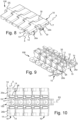
- the two guide bodies 202, 203 can be made in a single body generally having a 'U-like' shape, the arms of which consist of the two guide bodies 202, 203 between which the channel 206 remains defined. In the case of multi-way guides, it is also possible to make guide bodies 202, 203 of adjacent ways in a single body as shown in the accompanying figures 1-6 .
- the guide 200 can further comprise at least one straight section 209 upstream and/or downstream of the curved section 201.
- the straight section 209 comprises, in a known manner, raceways 210, 211 with a straight extension which are arranged spaced apart and parallel to each other, thus forming a track.
- Each raceway 210, 211 has at the top a respective flat upper support surface 212, 213 on which the chain 100 rests and runs.
- the guides 210, 211 are aligned with the guide bodies 202, 203 so as to form a continuous guide, in which the first flat surface 207, 208 at the top of the guide bodies 202, 203 is substantially coplanar with the upper support surface 212, 213 of the raceways 210, 211.
- Figures 1 to 6 show a portion of a so-called 'multi-way' conveyor, i.e., one in which there are several chains 100 side-by-side and next to which, in addition, conveyors 300 of other known type, e.g., belt conveyors, can run.
- a respective guide 200 is provided for each chain 100.
- the guide bodies 202, 203 and/or raceways 210, 211 of adjoining guides 200 can, as is known, be obtained as a single body or otherwise form an assembly.
- the components of a single chain 100 and the relative guide 200 have been numbered.
- the chain 100 runs along the guide 200 dragged by a driving unit generally comprising gear wheels, at least one of which is motorised and not shown or described as being of a known type.
- 'Running direction' means the direction coinciding (along straight stretches) or tangent (along curved stretches) to the longitudinal extension axis of the guide 200 shown in the accompanying figures by the dashed line DS.
- the chain 100 is generally closed on itself in a loop. Generally, furthermore, the chain 100 is also closed on itself in a loop, forming an upper forward section and a lower return section.
- the chain 100, or at least its upper section, is intended for the transport of products.
- Figures 1 to 6 show the chain 100 or its upper section;
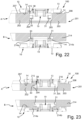
- figures 18 to 24 show, in section along a curved section 201, a chain 100 closed on itself in a loop forming an upper forward section A and a lower return section B.
- each link 10 comprises a plate body 12 which has:
- the first surface 13 is the upper surface of the plate body 12.
- the second surface 14 is not necessarily continuous and can comprise a plurality of discontinuous supports defining a common generic supporting and sliding plane, as for example shown in figures 9, 10 , 12 and 26 .
- the first surface 13 can be shaped or finished differently from what is shown in the accompanying figures, for example, it can comprise lightenings, coatings, ribs, projections, rollers or other features known to the person skilled in the art.
- the plate body 12 has, in plan, a generally rectangular shape and has a pair of end lateral surfaces 15, 16, a front edge 17 and a rear edge 18.
- the front edge 17 and/or the rear edge 18 are shaped to allow the lateral flexing of the chain 100 so that it can slide along curved paths; in particular, the rear edge 18, for example, can be chamfered, angled or tilted as seen in figures 8, 10 , 11 and 25 and in any case in a manner known to the person skilled in the art and, therefore, not further described.
- Each link 10 then comprises an articulation portion 19 which extends below the first surface 13 of the plate body 12 and substantially in the middle thereof.
- the articulation portion 19 and the plate body 12 are obtained in a single body.
- the articulation portion 19 and the plate body 12 are obtained in a single body obtained by moulding a polymeric (thermoplastic) material.
- the second surface 14 is the lower surface of the plate body 12 outside the articulation portion 19.
- the articulation portion 19 comprises at least one pair of housings 20, 21 transverse to the travel direction DS and each adapted to accommodate a respective pin 11 which articulates the link 10 with similar links 10, respectively preceding and following, to form the chain 100.
- the longitudinal axis of the pins 11 inserted in the housings 20, 21 has been indicated with the trace X-X; the longitudinal axes X-X are coplanar to a plane substantially parallel to the plane defined by the first surface 13 and extend along directions transverse to the travel direction DS.
- the housings 20, 21, respectively a first housing 20 and a second housing 21, are obtained in parts of the articulation portion 19 and the plate body 12 which are complementary to each other and intended to engage with each other to allow hinging between two consecutive links 10, as shown for example in figures 1-4 , 8-12 and 25-26.
- Each link 10 has at least one substantially flat reaction surface SR extending below the first surface 13 of the plate body 12 in a transverse plane, i.e., substantially orthogonal to less than a maximum angle of 7 ⁇ 8°, to the longitudinal axes X-X of the pins 11.
- the reaction surface SR is adapted to contact at least one portion of the lateral surface 204 of the guide body 202 defining the inner side of the curved path, generating a radial reaction force RR acting on the respective link 10 along a direction of action DRR extending above the longitudinal axes X-X of the pins 11 (see figures 7 and 7A ), along which pin axes, as is known, the radial force FR generated by the pulling action of the chain 100 along the curved section acts.
- the direction of action DRR can at most coincide with the longitudinal axes X-X, but not lie below them with respect to the first surface 13.
- the contact between the reaction surface SR and the lateral surface 204 of the guide body 202 defining the inner side of the curved path ideally occurs along a 'generating line' of the curved surface forming the inner side of the curved path itself.
- the contact is never punctual, but occurs along a surface which extends in height along such a 'generating line', a height which is essentially equal to the height H SR , measured orthogonally to the first surface 13, of the reaction surface SR in contact with a corresponding portion of the lateral surface 204 defining the inner side of the curved path.
- the radial reaction force RR acts along a direction DRR intersecting the reaction surface SR at a substantially median position with respect to the extension in height H SR of the reaction surface SR in contact with a corresponding portion of the lateral surface 204 defining the inner side of the curved path.
- the direction DRR along which the radial reaction force RR acts is substantially at the centreline (with respect to the extension in height H SR ) of the reaction surface SR in contact with a corresponding portion of the lateral surface 204 defining the inner side of the curved path.
- the direction DRR is offset upwards (i.e., towards the first surface 13) at a generally non-zero distance S from the direction of the longitudinal axes X-X along which the radial force FR instead acts.
- the distance S defines the arm between the radial force FR acting on the pin 11 and the radial reaction force RR acting on the hinge.
- the direction DRR is therefore closer to the first surface 13 with respect to the direction of the longitudinal axes X-X.
- the reaction surface SR comprises at least one section extending above the second surface 14 of the plate body 12.
- the reaction surface SR comprises at least one section extending in height (height being measured orthogonally to the first surface 13 or to the transport plane defined thereon) above the second surface 14 of the plate body 12.
- reaction surface SR comprises at least one section extending in height above the second surface 14 of the plate body 12 which is intended to rest and slide on the upper support surface 212, 213 of straight sections 209 of the guide 200.
- the reaction surface SR at least partially 'penetrates' the plate body 12 and in particular the second surface 14 thereof; that is, the reaction surface SR extends for at least a stretch section the thickness of the plate body 12, 'intersecting' it.
- reaction surface SR extends for at least a section of its extension in height H SR to contact the lateral surface 204 defining the inner side of the curve above the second surface 14 of the plate body 12 so that the distance S between the direction DRR and the longitudinal axes X-X is non-zero.
- the longitudinal axes of the housings 20, 21 - and thus, barring any known coupling clearances, the longitudinal axes X-X of the pins 11 inserted therein - extend along directions parallel to each other and coplanar to a plane parallel to the second surface 14 of the plate body 12 and which is located between the first surface 13 and the second surface 14 thereof.
- the housings 20, 21 are arranged so that the longitudinal axes X-X of the pins 11 inserted therein lie in a plane parallel to the second surface 14 of the plate body 12 and arranged thereabove by a non-zero distance (and below the first surface 13). Since the second surface 14 of the plate body 12 is intended to rest and slide on the upper support surface 212, 213 of the raceways 210, 211 of straight sections 209 of the guide 200, in use the longitudinal axes X-X of the pins 11 are above the upper support surface 212, 213 of the raceways 210, 211.
- the longitudinal axes X-X can extend in a plane which is below the second surface 14 ( figure 7A ), as long as the condition is satisfied where the reaction surface SR extends for at least a section of its extension in height H SR above and interpenetrating the second surface 14, and has an extension in height H SR such that, in contact with the lateral surface 204 defining the inner side of the curved path, its centre line, along which the radial reaction force RR acts approximately, is located above (i. e., nearer to the first surface 13) the longitudinal axes X-X, being offset upwards with respect thereto by a non-null distance S or at most a zero distance (S>0).
- the arrow FR indicates the radial force acting along the longitudinal axis X-X of the pins 11 and which is generated as a result of the pulling action of the chain 100 when it runs along a curved section 201.
- the radial force FR tends to force the chain 100 towards the inner side of the curved section 201 generating a tilting torque which tends to lift the chain 100 at the outer side of the curved section.
- the radial force FR acts in the pushing direction of the chain 100 towards the inner side of the curved section 201, bringing the reaction surface SR of each link 10 into sliding contact with the lateral surface 204 of the guide body 202 on the inner side of the curved section 201.
- a radial reaction force indicated by the arrow RR is generated, which acts in the opposite direction to the radial force FR.
- the radial reaction force RR acts along a direction DRR which is essentially in the median position of the reaction surface SR, i.e., essentially in the middle of the extension in height H SR of the reaction surface SR in contact with the lateral surface 204 which defines the inner side of the curved path.
- the reaction surface SR and, in particular, its height H SR is dimensioned so that the direction of action DRR of the reaction force RR is at a higher height with respect to the direction of action of the radial force FR, i.e., at a higher height with respect to the longitudinal axes X-X of the pins 11.
- a torque C is generated which acts on the link 10, retaining it within the curved section 201 and preventing it, in particular, from lifting along the outer side thereof.
- reaction surface SR extends for at least a section of its extension in height H SR above the second surface 14 of the plate body 12, interpenetrating it.
- each link 10 makes it possible to reduce the overall height of each link 10 with respect to the known type of links - and, in particular, with respect to the links such as those known from EP0527584B1 - and, therefore, also the relative weight, with consequent advantages not only in terms of the use and cost of the materials required to make the links 10, but also in terms of reducing the power used to drag the conveyor chain 100 obtained therewith.
- link 10 is retained in place along the curved sections 201 without any need for the use of further expedients such as tabs, inclined surfaces ('bevels') or components adapted to react to magnetic fields.
- both the link 10 and the pins 11 can be made of polymeric materials.
- the link 10 can be made of a first thermoplastic material and the pins 11 can be made of a second thermoplastic material.
- first thermoplastic material and the second thermoplastic material belong to the same polymeric family and, for example, are chosen from the acetal resin group (POM polyoxymethylene).
- the first thermoplastic material and the second thermoplastic material have different mechanical and/or physical features; for example, they may have a different wear resistance and/or a different coefficient of friction.
- the link 10 can be made of lubricated acetal resin with low friction coefficient features, while the pins 11 can be made of acetal resin with high mechanical strength features. The opposite is not excluded.
- links 10 and pins 11 of homologous, related or compatible polymeric materials, meaning polymeric materials which, belonging to the same polymeric family, can be disposed of/recycled together or in a single supply chain, it is possible to dispose of/recycle the chain 100 in its entirety, without the need to disassemble its components and to differentiate its disposal and/or recycling.
- the plate body 12 and the articulation portion 19 are made in a single body.
- the articulation portion 19 comprises:
- the two eyelets 21a, 21b are parallel to each other and spaced so as to form a space 22 therebetween adapted to accommodate the first housing 20 of a similar link 10.
- the first slot 20 of an adjacent link 10 can be inserted so that the axial hole of the latter is aligned with the axial holes of the two eyelets 21a, 21b to receive a pin 11 connecting two successive links 10 to each other.
- the plate body 12 has an opening 23 obtained at the space 22.
- the hinge portion 19 then comprises a pair of shaped ribs 24, 25 which extend below the first surface 13 of the plate body 12 and connect the axial ends of the first housing 20 to the two eyelets 21a, 21b.
- the first housing 20, the one defined at the rear edge 18, is in turn formed by a pair of eyelets 20a, 20b and the second housing 21, the one defined at the front edge 17, by three corresponding eyelets 21a, 21b and 21c, one being housed in spaces delimited by the others and vice versa.
- the latter solution which, for the same load, makes it possible to limit the elongation of the chain due to flexural deformation of the pin 11 with respect to the previously described solution.
- Such a conformation of the housings 20, 21 can be adopted in all the embodiments shown in the accompanying figures.
- the plate body 12 comprises below the first surface 13 at least one substantially straight groove 26a, 26b extending substantially parallel to the travel direction DS and whose innermost side at least partially defines the reaction surface SR.
- the plate body 12 comprises a pair of grooves 26a, 26b arranged symmetrically with respect to a median plane orthogonal to the longitudinal axes X-X.
- the reaction surface SR is obtained on a respective side of the articulation portion 19, which thus forms the innermost side of the respective groove 26a, 26b.
- a respective sidewall 27, 28 which extends below the first surface 13 of the plate body 12.
- the sidewalls 27, 28 are flat and extend in planes transverse or orthogonal to the longitudinal axes X-X. In the embodiment shown in the accompanying figures ( figures 10 and 12 ), the sidewalls 27, 28 form a non-zero angle with a median plane orthogonal to the longitudinal axes X-X; the sidewalls 27, 28 are slightly tilted towards each other converging towards the rear edge 18.
- the sidewalls 27, 28 are crossed by a respective hole aligned with one of the two housings 20, 21 to allow the insertion of the pin 11 in the latter; in the embodiment shown, the sidewalls 27, 28 are crossed by a respective hole coaxial to that of the eyelets 21a, 21b.
- the reaction surface SR is defined at the outer surface of the sidewall 27, 28 on the inner side of the curved section 201.
- the sidewalls 27, 28 can form the sides of the articulation portion 19 and their outer surface forms the innermost side of the respective groove 26a, 26b, forming the reaction surface SR.
- the articulation portion 19 and/or the sidewalls 27,28 can extend for a section below the second surface 14 and which, in use, is received in the channel 206.
- the second surface 14 is interrupted by at least one arcuate recess 29 aligned with one of the two housings 20, 21 to allow the insertion of the pin 11 in the latter.
- the recess 29 is aligned with the second housing 21, i.e., with the eyelets 21a, 21b.
- the plate body 12 comprises a pair of wings 12a, 12b extending from the opposite sides of the articulation portion 19, each of which has:
- the second surface 14 of the plate body 12 consists of the lower surface of the wings 12a, 12b at their second thickness portion equal to the second thickness S2.
- the reaction surface SR is defined at the first portion of the two wings 12a, 12b which has a thickness equal to the first thickness S1.
- each wing follow each other starting from the respective side of the articulation portion 19.
- first portion of each of the two wings 12a, 12b is laterally delimited by the second portion of the respective wing 12a, 12b and by the corresponding side of the articulation portion 19 or by the respective sidewall 27, 28, thus forming a respective groove 26a, 26b.
- the first thickness S1 is less than the thickness S2 (second thickness) which the plate body 12 has externally to the articulation portion 19 at the portion thereof defining the second surface 14 adapted to rest on and slide along the upper support surface 212, 213 of raceways 210, 211 defining straight sections 209 of the guide 200 (S1 ⁇ S2).
- S1 is the minimum thickness which the plate body 12 has externally to the articulation portion 19.
- the first thickness S1 is less than or equal to half of the second thickness S2 (S1 ⁇ S2/2).
- the first thickness S1 is determined as a function of the minimum mechanical strength of the plate body 12.
- the second thickness S2 is also determined as a function of the flanking of chain 100 with other chains or conveyors.
- the first thickness S1 can vary between 3 mm and 5 mm and the second thickness S2 is greater than 5 mm.
- the second thickness S2 is greater than twice the first thickness S1 or regardless at least 5 mm greater than the first thickness S1.
- the second thickness S2 can vary between 8.7 mm and 12.7 mm (8.7 mm ⁇ S2 ⁇ 12.7 mm),
- the plate body 12 has, externally to the articulation portion 19, a maximum thickness equal to that of the second portion of its wings 12a, 12b (second thickness S2) and a minimum thickness equal to that of the first portion of its wings 12a, 12b (first thickness S1).
- the reaction surface SR has a height H SR measured orthogonally to the plane defined by the first surface 13 of the plate body 12 equal to or greater than 7 mm, preferably greater than or equal to 9 mm.
- the overall height of the link 10 can be reduced with respect to that of the known links by a dimension equal to the difference between the second thickness S2 and the first thickness S1 (S2-S1).
- the pins 11 have a diameter greater than 5 mm, preferably between 7 mm and 10 mm and even more preferably 8 mm.
- the link 10 can comprise at least one pair of teeth 30, 31 projecting in a direction transverse to the travel direction DS and which are defined, facing or opposite each other, below the first surface 13 of the plate body 12.
- Such teeth 30, 31, if present, are intended to slidingly engage with a complementary return support 214 of the chain 100 along the return path.
- the teeth 30, 31 do not interact with the guide 200 along the forward path.
- the teeth 30, 31 do not interact with corresponding elements obtained in the guide bodies 202, 203 defining the curved section 201 of the forward path, for example to make an obstacle to the lifting of the conveyor chain 100 (i.e., the guide bodies 202, 203 lack elements adapted to interact with the teeth 30, 31).
- the teeth 30, 31 only serve to support the conveyor chain 100 along the return path.
- the teeth 30, 31 can be obtained at the articulation portion 19 below the second surface 14 of the plate body 12.
- the teeth 30, 31 can be obtained in the thickness of the plate body 12, for example, they can be obtained in an overhang from the outermost side which delimits each groove 26a, 26b ( figure 21 ), facing each other.
- the curved guide segment or curved section 201 comprises at least one pair of guide bodies 202, 203 spaced apart from each other and having respective lateral surfaces 204, 205 facing each other and parallel to each other which delimit a curved path, in which one of such lateral surfaces 204, 205 defines the inner side of the curved path and the other of said lateral surfaces 204, 205 defines the outer side of the curved path.
- the guide body 202, 203 whose lateral surface 204, 205 defines the inner side of the curved path comprises at the top:
- the side of the projection 215 facing the lateral surface 204, 205 defining the outer side of the curved path constitutes (all and only) the portion of the lateral surface 204, 205 adapted to contact the reaction surface SR of the links 10.
- the projection 215 forms a second step 217 (undercut) at the lateral surface 204, 205.
- the side of the projection 215 facing the lateral surface 204, 205 defining the outer side of the curved path is coplanar with the remaining portion of the lateral surface 204, 205.
- the projection 215 is accommodated or couples with clearance in the respective groove 26a, 26b of the plate body 12 located on the inner side of the curved section 201.
- the guide body 202, 203 whose lateral surface 204, 205 forms the outer side of the curved path comprises at its top a first flat surface 207, 208 on which, in use, the second surface 14 of the plate bodies 12 of the links 10 is superimposed.
- the first flat surface 207, 208 can be totally flat ( figures 18 , 21 , 22 , 24 ) or it can have a rib 218 projecting thereabove ( figures 6 , 7 , 19 , 20 , 23 ) and serving as an external support for the plate body 12.
- the rib 218 is adapted to be housed or accommodated with clearance in the groove 26a, 26b of the plate body 12 located on the outer side of the curved section 201.
- the lateral surface 204, 205 of the guide body 202, 203 on the outer side of the curved section 201 can lack steps or projections.
- the two guide bodies 202, 203 can be made in a substantially U-like shaped body and guide bodies 202, 203 of side-by-side ways can be made in a single body ( figures 1-6 ). Between the two guide bodies 202, 203 the channel 206 in which the articulation portions 19 are accommodated remains defined.
- the curved guide segment (curved section 201) can comprise along the return path B of the chain 100 a return support 214 extending parallel to and below the curved path and having along its longitudinal extension at least one pair of transverse fins 214a, 214b on which pairs of teeth 30, 31 protruding transversely from each link 10 are slidingly supported to slidingly support the chain 100 along the return path.
- Figures 1 to 4 show a section of a conveyor comprising one or more chains 100 according to the present invention side by side with other conveyors 300.
- Each conveyor chain 100 runs along a guide 200 having at least one straight section 209 and at least one curved section 201 as described above.
- the second surface 14 of the plate bodies 12 is intended to rest on and run along the upper support surfaces 212, 213 of the raceways 210, 211 forming the straight section 209.
- the guide bodies 202, 203 forming the curved section 201 have at the top a first flat surface 207, 208 substantially coplanar with the upper support surfaces 212, 214.
- the guide body 202, 203 on the inner side of the curved section 201 has the respective lateral surface 204, 205 extending for at least one section, which is formed by the inner side of the projection 215, above the respective first flat surface 207, 208 to contact the reaction surface SR obtained in the links 10, in the thickness of the plate body 12.
- the chain 100 can therefore be used even in existing plants, without the need to replace the raceways 210, 211 or regardless the guides of the existing straight path sections or use different ones.
- the embodiment in figure 18 shows a chain 100 whose links 10 have pairs of teeth 30, 31 facing each other and obtained in projections which extend below the articulation portion 19.
- the guide body 202 on the inner side of the curved section has the lateral surface 204 free of steps or undercuts (the projection 15 is not protruding towards the middle of the channel 206) .
- the embodiment shown in figure 19 shows a chain 100 whose links 10 have pairs of teeth 30, 31 facing each other and obtained in projections which extend below the articulation portion 19. It can also be seen that the reaction surface SR is formed by the sides of the articulation portion 19 which are recessed with respect to the projections provided by the teeth 30, 31.
- the guide body 202 on the inner side of the curved section has the lateral surface 204 shaped with at least one step (second step 217) or undercuts (the projection 15 is protruding towards the middle of the channel 206).
- the embodiment shown in figure 20 differs from that of figure 19 in the sizing of the second surface 14, the grooves 26a, 26b and the relative projections 215 and the shape and arrangement of the teeth 30, 31.
- the embodiment shown in figure 21 differs from that of figure 18 , apart from the dimensions of the grooves 26a, 26b, in the arrangement of the teeth 30, 31 which are obtained by facing each other above the second surface 14 at the outermost sides of the grooves 26a, 26b, changing the shape of the return support 214.
- the embodiment shown in figure 22 shows a conveyor chain 100 whose links 10 have pairs of teeth 30, 31 opposite each other and obtained in projections which extend below the articulation portion 19.
- the guide body 202 on the inner side of the curved section has the lateral surface 204 free of steps or undercuts (the projection 15 is not protruding towards the middle of the channel 206) and the teeth 30, 31 do not protrude beyond the sides of the articulation portion 19.
- the return support 214 is shaped so as to have a T-shaped groove forming fins 214a, 214b on which the teeth 30, 31 slidingly rest.
- the embodiment shown in figure 23 differs from the one in figure 22 not only in the sizing of the grooves 26a, 26b and the second surface 14, but also in the fact that the teeth 30, 31 protrude externally from the articulation portion 19.
- the guide body 202 on the inner side of the curved section has the lateral surface 204 shaped with at least one step (second step 217) or undercuts (the projection 15 is protruding towards the middle of the channel 206 to contact the sides of the articulation portion 19 above the teeth 30, 31).
- the return support 214 has a T-shaped groove whose fins 214a, 214b are shaped to fit in the grooves 26a, 26b below the teeth 30, 31.
- the embodiment shown in figure 24 differs from that of figure 18 in that the links do not have teeth 30, 31, in which case a further support plate 219 must be provided along the return path.
- a conveyor comprising at least one curved conveyor chain and a curved, forward and/or return guide support, as described above and as claimed.
- the curvilinear conveyor chain according to the present invention has a high degree of stability and slidability even along the curved sections and is easy to assemble and disassemble.
- the stability along curved sections of the conveyor chain according to the present invention is ensured by the resultant alone of the radial reaction force RR as described above, there being no other known retention elements or systems of known type, such as a magnetic system, opposite or facing retention tabs, inclined tabs ('bevels') or other.
- reaction surface SR - which, when the chain runs along curved stretches, is adapted to contact the lateral surface defining the inner side of the curved guide path - so that it extends for at least one section in the thickness of the plate body 12, as described above, makes it possible to limit the overall height and weight of the links and thus of the conveyor chain.
- the articulation pin housings so that they are closer to the product support surface (first surface 13 of the plate body 12).
- the articulation pin housings can be made so that their longitudinal axes X-X lie on a plane intersecting the thickness of the plate body 12.
- a curvilinear conveyor chain 100 adapted to slide along a guide comprising at least one curved section
- the chain comprises a plurality of links 10 articulated to each other by respective articulation pins 11 and in which each link comprises a plate body 12 having a first surface 13 defining a support surface adapted to support products to be conveyed and an articulation portion 19 extending below the first surface 13 of the plate body and substantially in the middle thereof and comprising at least one pair of housings 20, 21 transverse to the travel direction of the conveyor chain along the guide 200 and each capable of accommodating a respective articulation pin 11 of the link having similar antecedent and subsequent links, respectively, in which the plate body 12 and the articulation portion 19 are made of a first thermoplastic material and in which the articulation pins 11 are made of a second thermoplastic material, the plate body 12 having, externally to the articulation portion 19, a maximum thickness S2 greater than 5 mm, advantageously between 8.7 mm and 12.7 mm, preferably 8.
- the link 10 can be made of a first thermoplastic material and the articulation pins 11 can be made of a second thermoplastic material.
- the first thermoplastic material and the second thermoplastic material belong to the same polymeric family and, for example, are chosen from the acetal resin group (POM polyoxymethylene).
- the first thermoplastic material and the second thermoplastic material have different mechanical and/or physical features; for example, they may have a different wear resistance and/or a different coefficient of friction.
- the link 10 can be made of lubricated acetal resin with low friction coefficient features, while the pins 11 are instead made of acetal resin with high mechanical strength features. The opposite is not excluded.
- links 10 and pins 11 of homologous, related or compatible polymeric materials, meaning polymeric materials which, belonging to the same polymeric family, can be disposed of/recycled together or in a single supply chain, it is possible to dispose of/recycle the chain 100 in its entirety, without the need to disassemble its components and to differentiate its disposal and/or recycling.
- the plate body 12 comprises a pair of wings 12a, 12b extending from the opposite sides of the articulation portion 19, each of which has:
- the plate body 12 comprises below the first surface 13 a second surface 14 which consists of the lower surface of the wings 12a, 12b at their second portion of thickness equal to the second thickness S2 (maximum thickness).
- first and the second portion of each wing follow each other starting from the respective side of the articulation portion 19.
- the first portion of each of the two wings 12a, 12b is laterally delimited by the second portion of the respective wing 12a, 12b and the corresponding side of the articulation portion 19.
- S1 is the minimum thickness which the plate body 12 has externally to the articulation portion 19.
- the first thickness S1 is less than or equal to half of the second thickness S2 (S1 ⁇ S2/2).
- the first thickness S1 is determined as a function of the minimum mechanical strength of the plate body 12.
- the second thickness S2 is also determined as a function of the flanking of chain 100 with other chains or conveyors.
- the first thickness S1 can vary between 3 mm and 5 mm and the second thickness S2 is greater than 5 mm.
- the second thickness S2 is greater than twice the first thickness S1 or regardless at least 5 mm greater than the first thickness S1.
- the first thickness S1 (minimum thickness) is between 3 mm and 5 mm and the second thickness S2 (maximum thickness) is between 8.7 mm and 12.7 mm: 3 mm ⁇ S1 ⁇ 5 mm and 8.7 mm ⁇ S2 ⁇ 12.7 mm.
Landscapes
- Engineering & Computer Science (AREA)
- Mechanical Engineering (AREA)
- Chain Conveyers (AREA)
- Forklifts And Lifting Vehicles (AREA)
- Devices For Conveying Motion By Means Of Endless Flexible Members (AREA)
- Framework For Endless Conveyors (AREA)
Applications Claiming Priority (1)
| Application Number | Priority Date | Filing Date | Title |
|---|---|---|---|
| IT102021000031997A IT202100031997A1 (it) | 2021-12-21 | 2021-12-21 | Catena di trasporto curvilinea atta a scorrere lungo una guida comprendente almeno un tratto curvo. |
Publications (2)
| Publication Number | Publication Date |
|---|---|
| EP4227245A2 true EP4227245A2 (de) | 2023-08-16 |
| EP4227245A3 EP4227245A3 (de) | 2023-10-25 |
Family
ID=80461961
Family Applications (1)
| Application Number | Title | Priority Date | Filing Date |
|---|---|---|---|
| EP22214444.6A Pending EP4227245A3 (de) | 2021-12-21 | 2022-12-19 | Kurvenförmige förderkette, die zum laufen entlang einer führung mit mindestens einem gebogenen abschnitt geeignet ist |
Country Status (4)
| Country | Link |
|---|---|
| US (1) | US12214964B2 (de) |
| EP (1) | EP4227245A3 (de) |
| CN (1) | CN116280902A (de) |
| IT (1) | IT202100031997A1 (de) |
Families Citing this family (6)
| Publication number | Priority date | Publication date | Assignee | Title |
|---|---|---|---|---|
| USD1103545S1 (en) * | 2023-07-21 | 2025-11-25 | Movex S.P.A. | Conveyor module |
| USD1103546S1 (en) * | 2023-07-21 | 2025-11-25 | Movex S.P.A. | Conveyor module |
| USD1107369S1 (en) * | 2023-07-21 | 2025-12-23 | Movex S.P.A. | Conveyor module |
| USD1104399S1 (en) * | 2023-07-21 | 2025-12-02 | Movex S.P.A. | Conveyor module |
| USD1124577S1 (en) * | 2024-09-06 | 2026-04-28 | Movex S.P.A. | Link of a conveyor chain |
| USD1124576S1 (en) * | 2024-09-06 | 2026-04-28 | Movex S.P.A. | Link of a conveyor chain |
Citations (10)
| Publication number | Priority date | Publication date | Assignee | Title |
|---|---|---|---|---|
| US3262550A (en) | 1964-05-11 | 1966-07-26 | Conveyor Specialties Company | Conveyor chain |
| US4096943A (en) | 1975-11-28 | 1978-06-27 | Rexnord Inc. | Snap-on top plate assembly |
| GB2108920A (en) | 1981-11-10 | 1983-05-25 | Regina Ind Srl | Conveying chain having two types of links hinged together alternately |
| GB2153323A (en) | 1984-01-26 | 1985-08-21 | Rexnord Kette Gmbh & Co Kg | Curve-negotiating plate conveyor |
| EP0527584B1 (de) | 1991-08-12 | 1996-04-10 | Rexnord Corporation | Seitlich schwenkbare Förderkette |
| EP0711714A1 (de) | 1994-11-08 | 1996-05-15 | REGINA SUD S.p.A. | Kettenförderer mit verbesserten Festigkeits- und Gleiteigenschaften |
| EP0903307A1 (de) | 1997-09-18 | 1999-03-24 | REGINA SUD S.p.A. | Magnetische Führung |
| WO2011067737A1 (en) * | 2009-12-04 | 2011-06-09 | Bett Sistemi S.R.L. | Conveyor |
| WO2016131879A1 (en) | 2015-02-18 | 2016-08-25 | Rexnord Flattop Europe S.R.L. | Guide for chain for articles conveyor |
| WO2019016716A1 (en) | 2017-07-19 | 2019-01-24 | Regina Catene Calibrate S.P.A. | CURVED MAGNETIC GUIDE HAVING AN IMPROVED MODULAR STRUCTURE FOR GUIDING THE CHAIN OF A CONVEYOR CHAIN |
Family Cites Families (17)
| Publication number | Priority date | Publication date | Assignee | Title |
|---|---|---|---|---|
| GB1256590A (de) * | 1969-08-22 | 1971-12-08 | ||
| US5020656A (en) * | 1988-07-18 | 1991-06-04 | Faulkner William G | Flat top conveyor |
| US4961492A (en) * | 1988-07-22 | 1990-10-09 | Simplimatic Engineering Company | Article carrying conveyor and wearstrip set therefor |
| US5127515A (en) * | 1990-10-01 | 1992-07-07 | Maskinfabrikken Baeltix A/S | Chain link conveyor |
| US5178263A (en) * | 1991-11-27 | 1993-01-12 | International Paper Company | Modular track section for an endless conveyor |
| DE4140206A1 (de) * | 1991-12-05 | 1993-06-09 | Johann A. Krause Maschinenfabrik Gmbh, 2820 Bremen, De | Vorrichtung zum transport von gegenstaenden |
| DK170664B1 (da) * | 1992-04-21 | 1995-11-27 | Baeltix Maskinfabrikken As | Kædeledstransportør |
| US5779027A (en) * | 1996-02-14 | 1998-07-14 | Rexnord Corporation | Sideflexing conveyor including lubrication inserts |
| DE29807758U1 (de) * | 1998-04-29 | 1999-09-09 | Joh. Winklhofer & Söhne GmbH und Co KG, 81369 München | Plattenbandkette |
| US6164439A (en) * | 1998-12-16 | 2000-12-26 | Rexnord Corporation | Thermoplastic connecting pin |
| US6382405B1 (en) * | 2000-02-25 | 2002-05-07 | Kvp Plastic Belting, Inc. | Solid top radius conveyor belt |
| JP3584443B2 (ja) * | 2001-02-27 | 2004-11-04 | 山久チヱイン株式会社 | コンベヤシステムに於ける走行フレーム装置 |
| AU2003218624A1 (en) * | 2002-03-08 | 2003-09-29 | Uni-Chains A/S | Mould and method for manufacturing a plastic chain element and a locking pinarrangement to be used therewith |
| US9650211B1 (en) * | 2011-01-31 | 2017-05-16 | Span Tech Llc | Conveyor with enhanced cleaning capability |
| MX2015004619A (es) * | 2012-10-25 | 2016-01-12 | Solus Ind Innovations Llc | Dispositivos y metodos de indicación de desgaste del sistema de banda transportadora. |
| NL2012475B1 (nl) * | 2014-03-19 | 2016-01-08 | Ambaflex Int B V | Transporteur voor het in hoogterichting transporteren van goederen. |
| EP3853155B1 (de) * | 2018-09-21 | 2024-04-24 | Rexnord Flattop Europe S.r.l. | Kettenglied für ein artikelförderband |
-
2021
- 2021-12-21 IT IT102021000031997A patent/IT202100031997A1/it unknown
-
2022
- 2022-12-19 EP EP22214444.6A patent/EP4227245A3/de active Pending
- 2022-12-19 US US18/084,246 patent/US12214964B2/en active Active
- 2022-12-21 CN CN202211655194.XA patent/CN116280902A/zh active Pending
Patent Citations (10)
| Publication number | Priority date | Publication date | Assignee | Title |
|---|---|---|---|---|
| US3262550A (en) | 1964-05-11 | 1966-07-26 | Conveyor Specialties Company | Conveyor chain |
| US4096943A (en) | 1975-11-28 | 1978-06-27 | Rexnord Inc. | Snap-on top plate assembly |
| GB2108920A (en) | 1981-11-10 | 1983-05-25 | Regina Ind Srl | Conveying chain having two types of links hinged together alternately |
| GB2153323A (en) | 1984-01-26 | 1985-08-21 | Rexnord Kette Gmbh & Co Kg | Curve-negotiating plate conveyor |
| EP0527584B1 (de) | 1991-08-12 | 1996-04-10 | Rexnord Corporation | Seitlich schwenkbare Förderkette |
| EP0711714A1 (de) | 1994-11-08 | 1996-05-15 | REGINA SUD S.p.A. | Kettenförderer mit verbesserten Festigkeits- und Gleiteigenschaften |
| EP0903307A1 (de) | 1997-09-18 | 1999-03-24 | REGINA SUD S.p.A. | Magnetische Führung |
| WO2011067737A1 (en) * | 2009-12-04 | 2011-06-09 | Bett Sistemi S.R.L. | Conveyor |
| WO2016131879A1 (en) | 2015-02-18 | 2016-08-25 | Rexnord Flattop Europe S.R.L. | Guide for chain for articles conveyor |
| WO2019016716A1 (en) | 2017-07-19 | 2019-01-24 | Regina Catene Calibrate S.P.A. | CURVED MAGNETIC GUIDE HAVING AN IMPROVED MODULAR STRUCTURE FOR GUIDING THE CHAIN OF A CONVEYOR CHAIN |
Also Published As
| Publication number | Publication date |
|---|---|
| EP4227245A3 (de) | 2023-10-25 |
| IT202100031997A1 (it) | 2023-06-21 |
| US20230192407A1 (en) | 2023-06-22 |
| US12214964B2 (en) | 2025-02-04 |
| CN116280902A (zh) | 2023-06-23 |
Similar Documents
| Publication | Publication Date | Title |
|---|---|---|
| EP4227245A2 (de) | Kurvenförmige förderkette, die zum laufen entlang einer führung mit mindestens einem gebogenen abschnitt geeignet ist | |
| EP0663354B1 (de) | Förderband | |
| EP1723056B1 (de) | Förderband und montageverfahren | |
| EP0527584A1 (de) | Seitlich schwenkbare Förderkette | |
| US3664619A (en) | Chain for supporting energy conveying means,and chain link therefor | |
| US8272503B2 (en) | Support device for a conveyor installation and method for operation of a conveyor installation | |
| US20110062001A1 (en) | Conveyor belt with guide means for curvilinear routes and modules for it | |
| US3529715A (en) | Stamped side-flex conveyor chain | |
| US5305869A (en) | Chain link conveyor | |
| US4150584A (en) | Double flexing chain | |
| EP1692060A1 (de) | Kurvengängige förderkette mit doppelquerverbindern | |
| EP2794437B1 (de) | Lösbare lasche für eine modulare gurtverbindung | |
| EP3572358B1 (de) | Tragstruktur mit verbessertem boden für einen gelenkigen gliederförderer | |
| KR102540527B1 (ko) | 롤러 컨베이어 표면을 갖는 모듈식 컨베이어 벨트용 모듈 및 이러한 복수의 모듈에 의해 형성된 모듈식 컨베이어 벨트 | |
| EP0420907B1 (de) | Förderband | |
| EP1655243B1 (de) | Modulare Förderanordnung mit geringem Staudruck | |
| US5425439A (en) | Coin escalator | |
| EP3105153A1 (de) | Förderer zum transport von produkten und verbindung für förderer | |
| CN110342190B (zh) | 返回导引装置及导引装置 | |
| US12584538B2 (en) | Energy chains for long travels, in particular with rollers | |
| CN113795686A (zh) | 用于能量引导链的疲劳强度地设计的侧板 | |
| EP3962840B1 (de) | Glied für modulares förderband | |
| EP0189413B1 (de) | Gleitschuhanordnung | |
| EP4370450A1 (de) | Förderkettenglied und förderkette mit einem solchen kettenglied und fördersystem | |
| CN217599505U (zh) | 一种模块化带单元及模块化输送带 |
Legal Events
| Date | Code | Title | Description |
|---|---|---|---|
| PUAI | Public reference made under article 153(3) epc to a published international application that has entered the european phase |
Free format text: ORIGINAL CODE: 0009012 |
|
| STAA | Information on the status of an ep patent application or granted ep patent |
Free format text: STATUS: THE APPLICATION HAS BEEN PUBLISHED |
|
| AK | Designated contracting states |
Kind code of ref document: A2 Designated state(s): AL AT BE BG CH CY CZ DE DK EE ES FI FR GB GR HR HU IE IS IT LI LT LU LV MC ME MK MT NL NO PL PT RO RS SE SI SK SM TR |
|
| PUAL | Search report despatched |
Free format text: ORIGINAL CODE: 0009013 |
|
| P01 | Opt-out of the competence of the unified patent court (upc) registered |
Effective date: 20230821 |
|
| AK | Designated contracting states |
Kind code of ref document: A3 Designated state(s): AL AT BE BG CH CY CZ DE DK EE ES FI FR GB GR HR HU IE IS IT LI LT LU LV MC ME MK MT NL NO PL PT RO RS SE SI SK SM TR |
|
| RIC1 | Information provided on ipc code assigned before grant |
Ipc: B65G 21/16 20060101ALI20230915BHEP Ipc: B65G 21/22 20060101ALI20230915BHEP Ipc: B65G 17/08 20060101AFI20230915BHEP |
|
| STAA | Information on the status of an ep patent application or granted ep patent |
Free format text: STATUS: REQUEST FOR EXAMINATION WAS MADE |
|
| 17P | Request for examination filed |
Effective date: 20240306 |
|
| RBV | Designated contracting states (corrected) |
Designated state(s): AL AT BE BG CH CY CZ DE DK EE ES FI FR GB GR HR HU IE IS IT LI LT LU LV MC ME MK MT NL NO PL PT RO RS SE SI SK SM TR |
|
| STAA | Information on the status of an ep patent application or granted ep patent |
Free format text: STATUS: EXAMINATION IS IN PROGRESS |
|
| 17Q | First examination report despatched |
Effective date: 20250613 |