EP4227249A1 - Procédé de construction de rail de guidage d'ascenceur et dispositif de construction - Google Patents
Procédé de construction de rail de guidage d'ascenceur et dispositif de construction Download PDFInfo
- Publication number
- EP4227249A1 EP4227249A1 EP20957583.6A EP20957583A EP4227249A1 EP 4227249 A1 EP4227249 A1 EP 4227249A1 EP 20957583 A EP20957583 A EP 20957583A EP 4227249 A1 EP4227249 A1 EP 4227249A1
- Authority
- EP
- European Patent Office
- Prior art keywords
- rail
- side rail
- rail bracket
- bracket
- drill screw
- Prior art date
- Legal status (The legal status is an assumption and is not a legal conclusion. Google has not performed a legal analysis and makes no representation as to the accuracy of the status listed.)
- Pending
Links
Images




Classifications
-
- B—PERFORMING OPERATIONS; TRANSPORTING
- B66—HOISTING; LIFTING; HAULING
- B66B—ELEVATORS; ESCALATORS OR MOVING WALKWAYS
- B66B19/00—Mining-hoist operation
- B66B19/002—Mining-hoist operation installing or exchanging guide rails
-
- B—PERFORMING OPERATIONS; TRANSPORTING
- B66—HOISTING; LIFTING; HAULING
- B66B—ELEVATORS; ESCALATORS OR MOVING WALKWAYS
- B66B7/00—Other common features of elevators
- B66B7/02—Guideways; Guides
- B66B7/023—Mounting means therefor
- B66B7/024—Lateral supports
Definitions
- the present invention relates to an elevator guide rail installation method and an elevator guide rail apparatus, and particularly to an elevator guide rail installation method and an elevator guide rail installation apparatus suitable for fixing a guide rail for guiding upward and downward movement of a car, a counterweight, and the like, to a predetermined position of a hoistway, via brackets, using drill screws.
- PTL 1 and PTL 2 disclose elevator guide rail fixture apparatuses for fixing a guide rail for guiding upward and downward movement of a car, a counterweight, and the like to a predetermined position of a hoistway, via brackets, using drill screws, and that are capable of reducing a burden of a worker in the installation of the guide rail, and that is also capable of bearing a horizontal load of an earthquake.
- PTL 1 mentioned above discloses an elevator guide rail fixture apparatus including: a wall-side rail bracket that is fixed to a wall surface of a hoistway in an elevator; and a rail-side rail bracket that is disposed overlapping with the wall-side rail bracket and that is fixed to a guide rail.
- a first fastening portion and a second fastening portion are provided in a section where the wall-side rail bracket overlap with each other.
- the first fastening portion includes: a first long hole provided to the wall-side rail bracket and a second long hole provided on the rail-side rail bracket, via which the rail-side rail bracket and the wall-side rail bracket are fixed to each other; a bolt passed through the first long hole and the second long hole; and a nut screwed onto the bolt, with the wall-side rail bracket and the rail-side rail bracket interposed therebetween.
- the second fastening portion is provided as a pair of drill screws by which the rail-side rail bracket and the wall-side rail bracket are fastened to each other more firmly than the first fastening portion, and each of the drill screws is disposed outside of the first fastening portion in the width direction of the guide rail.
- an elevator guide rail fixture apparatus including: a wall-side rail bracket that has a first long hole and that is fixed to a wall surface of a hoistway in an elevator; a rail-side rail bracket that has a second long hole in an overlapping section where the rail-side rail bracket overlaps with the wall-side rail bracket, and by which a car guide rail for guiding a car and a counterweight guide rail for guiding a counterweight are fixed; and a first fastening portion and a second fastening portion.
- the first fastening portion includes a bolt that is movably passed through the first long hole and the second long hole, and a nut screwed onto the bolt to hold the wall-side rail bracket and the rail-side rail bracket, the first fastening portion being provided in a section in which the wall-side rail bracket and the rail-side rail bracket overlap each other, and holding the rail-side rail bracket against the wall-side rail bracket at a position within a range across which the bolt is relatively movable with respect to the first long hole and the second long hole.
- the second fastening portion is a drill screw for fixing the rail-side rail bracket to the wall-side rail bracket, at a stronger force than that exerted by the first fastening portion, at a position not interfering with the first long hole, even when the rail-side rail bracket moves to any position within a movable range of the first fastening portion, with respect to the wall-side rail bracket.
- the apparatuses disclosed in PTL 1 and PTL 2 improves the workability with the use of a drill screw.
- the drill screw needs to be installed straight.
- a gap is ensured between the drill screw and the bracket, so as to avoid repetitive applications of load.
- the drill screw may be installed off the center, or the drill screw may be installed obliquely, so that the drill screw may become installed with no gap between the drill screw and the bracket, and end up interfering with the bracket. The drill screw itself may then eventually become damaged.
- the present invention has been made in consideration of the points described above, and an object of the present invention is to provide an elevator guide rail installation method and an elevator guide rail installation apparatus capable of installing a drill screw without tilt, and of eliminating the risk of the drill screw interfering with the bracket, and damages of the drill screw itself, even when the drill screw is used in fixing a wall-side rail bracket to a rail-side rail bracket.
- an elevator guide rail installation method is an elevator guide rail installation method in which a guide rail is fixed, via a rail-side rail bracket, to a wall-side rail bracket fixed to a wall surface of a hoistway in an elevator, and in which the wall-side rail bracket and the rail-side rail bracket are fastened with a drill screw
- the elevator guide rail installation method characterized in including: installing a guide and a washer or a spacer between the drill screw and the rail-side rail bracket in a horizontal direction, the guide and the washer or the spacer having a diameter larger than a flange portion of the drill screw; and removing the guide after the drill screw is installed so as to ensure a gap between the rail-side rail bracket and the drill screw in the horizontal direction.
- an elevator guide rail installation apparatus is characterized in including: a drill screw that fixes a guide rail, via a rail-side rail bracket, to a wall-side rail bracket fixed to a wall surface of a hoistway in an elevator; a guide that is disposed between the drill screw and the rail-side rail bracket in a horizontal direction, that has a diameter larger than a flange portion of the drill screw, that is removed after the drill screw is installed, and that ensures a gap between the rail-side rail bracket and the drill screw in the horizontal direction; and a washer or a spacer that is disposed between the drill screw and the rail-side rail bracket in the horizontal direction, and that has a diameter larger than a flange portion of the drill screw.
- the wall-side rail bracket and the rail-side rail bracket are fixed using a drill screw, it is possible to install the drill screw without tilt, and the risk of the drill screw interfering with the bracket can be eliminated. Therefore, damages of the drill screw itself can be avoided.
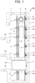
- FIG. 1 is a diagram illustrating a schematic configuration of an elevator apparatus 100 for which an elevator guide rail installation method according to a first embodiment of the present invention is to be used.
- the elevator apparatus 100 includes a hoistway 1 connecting stories of a building 2, a plurality of floors 2A provided in the respective stories of the building 2, and a car 4 that moves through the hoistway 1, and stops at each of the floors 2A.
- a car doorway 4A connects the floor 2A and the car 4.
- the car 4 is connected to one end of a main rope (not illustrated), and suspended in the hoistway 1, and a counterweight 5 counterbalancing the weight of the car 4 is connected to the other end of the main rope.
- a hoisting machine 3 that winds up the main rope, and a control panel (not illustrated) for controlling the operation of the hoisting machine 3 are installed in the upper area of the hoistway 1.
- the counterweight-side guide rail 9 is fixed to the wall surface 1A of the hoistway 1 via first rail brackets 10, using fasteners 16a each of which includes a bolt and a nut.
- the counterweight-side guide rail 8 and the car-side guide rail 7 are fixed to the wall surface 1A of the hoistway 1 via the second rail brackets 11, with fasteners 16b (see FIG. 2 ).
- the car-side guide rail 6 is fixed to the wall surface 1A of the hoistway 1 via third rail brackets 12, using fasteners 16c (see FIG. 2 ).
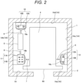
- FIG. 2 gives the details of how the car-side guide rails 6 and 7 and the counterweight-side guide rails 8 and 9 are fixed to the wall surface 1A of the hoistway 1.
- FIG. 2 is a horizontal sectional top view of the car 4, with the building 2 sectioned at a position including the car doorway 4A.
- the first rail bracket 10 includes a first wall-side rail bracket 10A and a first rail-side rail bracket 10B.
- the first rail-side rail bracket 10B holds the counterweight-side guide rail 9, and this first rail-side rail bracket 10B is fixed, via the first wall-side rail bracket 10A, to the wall surface lAd of the hoistway 1, using the fasteners 16a.
- the second rail bracket 11 includes a second wall-side rail bracket 11A and a second rail-side rail bracket 11B.
- the second rail-side rail bracket 11B holds the counterweight-side guide rail 8 and the car-side guide rail 7, and the second rail-side rail bracket 11B is fixed, via the second wall-side rail bracket 11A, to the wall surface 1Ab of the hoistway 1, using fasteners 16b.
- the third rail bracket 12 includes a third wall-side rail bracket 12A and a third rail-side rail bracket 12B.
- the third rail-side rail bracket 12B holds the car-side guide rail 6, and the third rail-side rail bracket 12B is fixed, via the third wall-side rail bracket 12A, to the wall surface 1Ac of the hoistway 1, using the fasteners 16c.
- rail clip bolts 17a and 17b are passed through the first rail-side rail bracket 10B, and the counterweight-side guide rail 9 is fixed by nuts 18a and 18b passed through the rail clip bolts 17a and 17b, respectively, and by rail clips 19a and 19b that tighten from the opposite side of the nuts 18a and 18b, respectively.
- the first wall-side rail bracket 10A has anchor bolt fixing holes (not illustrated). By selectively passing anchor bolts 10H1 and 10H2 through the anchor bolt fixing holes, the first wall-side rail bracket 10A is fixed to the wall surface 1A of the hoistway 1 (see FIG. 3 ).
- the counterweight-side guide rail 9 will be explained as an example of the four guide rails, and the explanations of the counterweight-side guide rail 8 and the car-side guide rails 6 and 7 will be omitted.
- the counterweight-side guide rail 9 is fixed, via the first rail bracket 10, to the wall surface 1A of the hoistway 1 with the fasteners 16a, as described above, but the first wall-side rail bracket 10A and the first rail-side rail bracket 10B making up the first rail bracket 10 are fastened with the drill screws 19A and 19B, as well as with the friction fixing bolts 15A and 15B, as be described later.
- each of the first wall-side rail bracket 10A and the first rail-side rail bracket 10B according to the present embodiment has an L-shaped cross section.
- the first wall-side rail bracket 10A is fixed to the wall surface 1A in the hoistway 1.
- the counterweight-side guide rail 9 is fixed to the short-side portion 10B' of the first rail-side rail bracket 10B having an L-shaped cross section, and the long-side portion 10A" of the first wall-side rail bracket 10A and the long-side portion 10B" of the first rail-side rail bracket 10B are fastened to each other with drill screws 19A and 19B and friction fixing bolts 15A and 15B.
- the first wall-side rail bracket 10A and the first rail-side rail bracket 10B serve to fasten with the frictional force of the friction fixing bolts 15A and 15B. If the friction fixing bolts 15A and 15B slip at the time of some unordinary event such as an earthquake, the load is received by the drill screws 19A and 19B.
- each of the long-side portion 10A" of the first wall-side rail bracket 10A and the long-side portion 10B" of the first rail-side rail bracket 10B according to the present embodiment are provided with a pair of through holes at a predetermined interval.
- a plurality of oblong holes (four oblong holes 10A1, 10A2, 10A3, and 10A4 provided to the long-side portion 10A" of the first wall-side rail bracket 10A (the oblong holes 10A3 and 10A4 not visible in FIGS. 4 and 5 ), and two oblong holes 10B1 and 10B2 provided to the long-side portion 10B" of the first rail-side rail bracket 10B) are disposed between the through-holes described above.
- the friction fixing bolts 15A and 15B are inserted into the respective oblong holes 10A3 and 10A4 provided to the long-side portion 10A" of the first wall-side rail bracket 10A, and also into the respective oblong holes 10B1 and 10B2 provided to the long-side portion 10B" of the first rail-side rail bracket 10B, with washers 17A and 17B interposed between the respective friction fixing bolts 15A and 15B and the first rail-side rail bracket 10B.
- first wall-side rail bracket 10A and the first rail-side rail bracket 10B are fastened to each other, while enabling an adjustment of the position at which the first wall-side rail bracket 10A and the first rail-side rail bracket 10B are fastened to each other, by moving the friction fixing bolts 15A and 15B inside the oblong holes 10B1 and 10B2, respectively.
- the drill screws 19A and 19B may be installed off the center, or the drill screws 19A and 19B may be installed obliquely, so that each of the drill screws 19A and 19B may become installed with no gap between the drill screw 19A or 19B and the first rail-side rail bracket 10B in the horizontal direction, and the drill screw 19A or 19B may end up interfering with the first rail-side rail bracket 10B.
- the drill screw 19A or 19B themselves may then eventually become damaged.
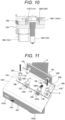
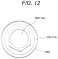
- the counterweight-side guide rail 9 is fixed, via the first rail-side rail bracket 10B, to the first wall-side rail bracket 10A, and before fastening the first wall-side rail bracket 10A and the first rail-side rail bracket 10B to each other using the drill screws 19A and 19B, guides 20A and 20B and washers or spacers 21A and 21B having diameters larger than those of flange portions 19A1 and 19B1 of the respective drill screws 19A and 19B (see FIG.
- a gap G (see (d) in FIG. 13 ) is thus ensured between the first rail-side rail bracket 10B and each of the drill screws 19A and 19B in the horizontal direction.
- an elevator guide rail installation apparatus in implementing the elevator guide rail installation method, includes: the drill screws 19A and 19B by which the counterweight-side guide rail 9 is fixed to the first wall-side rail bracket 10A with the first rail-side rail bracket 10B therebetween; the guide 20A and the guide 20B that are disposed between the drill screw 19A and the first rail-side rail bracket 10B and between the drill screw 19B and the first rail-side rail bracket 10B, respectively, in the horizontal direction, that have diameter larger than the diameters of the flange portions 19A1 and 19B1 (see FIG.
- each of the guides 20A and 20B has a cylindrical shape an upper portion of which is provided with a collar 20A1 or 20B1, in which each of the washers or the spacers 21A and 21B has a doughnut-like shape, and in which the doughnut-shaped washers or spacers 21A and 21B are installed inside cylindrical portions of the collars 20A1 and 20B1 of the guides 20
- the guide 20A and the washer or the spacer 21A are installed between the drill screw 19A and the first rail-side rail bracket 10B, and the guide 20B and the washer or the spacer 21B are installed between the drill screw 19B and the first rail-side rail bracket 10B, in the horizontal direction (see (a) of FIG. 13 ).
- the guides 20A and 20B and the washer or the spacers 21A and 21B have diameters larger than the flange portions 19A1 and 19B1 (see FIG. 10 ) of the drill screws 19A and 19B.
- the guides 20A and 20B are removed (see (d) of FIG. 13 ), and form a gap G (see (d) of FIG. 13 ) between each of the drill screws 19A and 19B and the first rail-side rail bracket 10B in the horizontal direction.
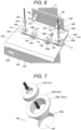
- Pilot holes 10B3 are formed at predetermined positions of the first rail-side rail bracket 10B as illustrated in FIG. 7 .
- the cylindrical guides 20A and 20B, each having the corresponding flange portion 20A1 or 20B1 on the upper part thereof, are then inserted into the respective pilot holes 10B3.
- the donut-shaped washers and spacers 21A and 21B are then installed, respectively, inside the cylindrical portions of the collars 20A1 and 20B1 of the respective guides 20A and 20B, and then the drill screws 19A and 19B are inserted, respectively, into the central holes of the donut-shaped washers or spacers 21A and 21B (see (a) of FIG. 13 ) .
- the guides 20A and 20B are pulled out using some predetermined means (e.g., a tool) so as to ensure the gap G (see (d) of FIG. 13 ) between the first rail-side rail bracket 10B and each of the drill screws 19A and 19B in the horizontal direction.
- some predetermined means e.g., a tool
- the gap G can be always ensured between each of the drill screws 19A and 19B and the first rail-side rail bracket 10B, and the guides 20A and 20B and the washers or the spacers 21A and 21B enable the drill screws 19A and 19B to be driven straightly. Therefore, even if the drill screws 19A and 19B are driven off the center, it is possible to ensure a gap G by pulling out each of the guides 20A and 20B. Hence, a long-term load, such as during that during the normal operation of the elevator apparatus 100, does not affect the drill screws 19A and 19B. Therefore, it is possible to eliminate the possibility of the drill screws 19A and 19B themselves becoming damaged.
- the embodiment has been explained above in detail to facilitate understanding of the present invention, and the present invention is not necessarily limited to the configuration including all of the elements explained above.
- a part of the configuration according to one of the embodiments may be replaced with a configuration according to another embodiment, and a configuration according to the other embodiment may be added to the configuration of the one embodiment.
- a part of the configuration according to each of the embodiments may be added to, deleted from, or replaced with the configuration according to the other embodiments.
Landscapes
- Lift-Guide Devices, And Elevator Ropes And Cables (AREA)
Applications Claiming Priority (1)
| Application Number | Priority Date | Filing Date | Title |
|---|---|---|---|
| PCT/JP2020/038439 WO2022079754A1 (fr) | 2020-10-12 | 2020-10-12 | Procédé de construction de rail de guidage d'ascenceur et dispositif de construction |
Publications (2)
| Publication Number | Publication Date |
|---|---|
| EP4227249A1 true EP4227249A1 (fr) | 2023-08-16 |
| EP4227249A4 EP4227249A4 (fr) | 2024-07-10 |
Family
ID=81207881
Family Applications (1)
| Application Number | Title | Priority Date | Filing Date |
|---|---|---|---|
| EP20957583.6A Pending EP4227249A4 (fr) | 2020-10-12 | 2020-10-12 | Procédé de construction de rail de guidage d'ascenceur et dispositif de construction |
Country Status (4)
| Country | Link |
|---|---|
| EP (1) | EP4227249A4 (fr) |
| JP (1) | JP7391237B2 (fr) |
| CN (1) | CN116368088A (fr) |
| WO (1) | WO2022079754A1 (fr) |
Families Citing this family (1)
| Publication number | Priority date | Publication date | Assignee | Title |
|---|---|---|---|---|
| CN114873422B (zh) * | 2022-04-24 | 2024-04-16 | 张家港市通达电梯装璜有限公司 | 一种电梯轨道中导轨的更换方法 |
Family Cites Families (10)
| Publication number | Priority date | Publication date | Assignee | Title |
|---|---|---|---|---|
| JPH0634905Y2 (ja) * | 1988-09-30 | 1994-09-14 | 日立工機株式会社 | 自動ねじ締機のねじ吸着機構 |
| JP2589145Y2 (ja) * | 1993-06-29 | 1999-01-20 | 株式会社椿本チエイン | ボルト止め部品のくぼみ先ねじによるずれ止め構造 |
| JP2011058548A (ja) * | 2009-09-09 | 2011-03-24 | Ricoh Co Ltd | 段付きネジ、締結構造及び画像形成装置 |
| ES1111480Y (es) * | 2014-04-08 | 2014-09-08 | Flaccox S L | Dispositivo de sujeción para roscado de tornillo |
| CN204041669U (zh) * | 2014-08-16 | 2014-12-24 | 超群机电制造(杭州)有限公司 | 带导向的自攻螺钉 |
| RU171777U1 (ru) * | 2016-04-25 | 2017-06-15 | федеральное государственное бюджетное образовательное учреждение высшего образования "Омский государственный университет им. Ф.М. Достоевского" | Магнитная отвертка |
| JP6382404B1 (ja) * | 2017-07-11 | 2018-08-29 | 東芝エレベータ株式会社 | エレベータ用ガイドレールの固定装置及び固定方法 |
| JP6510689B1 (ja) * | 2018-02-16 | 2019-05-08 | 東芝エレベータ株式会社 | エレベータ用ガイドレールの固定装置及びその固定方法 |
| JP6800900B2 (ja) * | 2018-02-26 | 2020-12-16 | 東芝エレベータ株式会社 | エレベータ用ガイドレールの固定装置及びその固定方法 |
| CN210161047U (zh) * | 2019-06-06 | 2020-03-20 | 上海蔚兰动力科技有限公司 | 螺钉导套管 |
-
2020
- 2020-10-12 CN CN202080105948.7A patent/CN116368088A/zh active Pending
- 2020-10-12 JP JP2022557227A patent/JP7391237B2/ja active Active
- 2020-10-12 WO PCT/JP2020/038439 patent/WO2022079754A1/fr not_active Ceased
- 2020-10-12 EP EP20957583.6A patent/EP4227249A4/fr active Pending
Also Published As
| Publication number | Publication date |
|---|---|
| JPWO2022079754A1 (fr) | 2022-04-21 |
| EP4227249A4 (fr) | 2024-07-10 |
| JP7391237B2 (ja) | 2023-12-04 |
| WO2022079754A1 (fr) | 2022-04-21 |
| CN116368088A (zh) | 2023-06-30 |
Similar Documents
| Publication | Publication Date | Title |
|---|---|---|
| JP3014952B2 (ja) | トラクションシーブエレベータ | |
| CN102892701B (zh) | 带有滚轮-小齿轮驱动器的升降机 | |
| RU2504512C2 (ru) | Лифтовая система и способ ее установки и модификации | |
| EP2097347B1 (fr) | Agencement dans la fourniture de câble au limiteur de vitesse | |
| EP3231757B1 (fr) | Support de rail de guidage | |
| US7025177B1 (en) | Elevator system without machine | |
| JP7434548B2 (ja) | エレベーター用ガイドレールの固定装置及びエレベーター装置 | |
| KR20070037995A (ko) | 승강실 및 승강로에 승강실의 지지 수단을 설치하는 방법 | |
| KR20160036787A (ko) | 기계실이 없는 엘리베이터 설치구조 | |
| JP7391237B2 (ja) | エレベーター用ガイドレールの施工方法及びその施工装置 | |
| US11383959B1 (en) | Method for expanding a rise of an elevator hoistway | |
| JPH07237847A (ja) | エレベーターの据付工法 | |
| JP2020117394A (ja) | エレベーターの釣合いおもり受治具および釣合いおもり受治具の取り付け方法 | |
| JP3170559B2 (ja) | エレベータの乗かごの固定装置 | |
| JP4927556B2 (ja) | エレベータ装置 | |
| EP1329411B1 (fr) | Ascenseur | |
| EP1687229A1 (fr) | Procede et appareil d'installation de cables d'ascenseur | |
| JPH05178564A (ja) | エレベータ制御用ケーブルの制振装置 | |
| JP7176649B2 (ja) | エレベーターの制御装置およびエレベーターシステム | |
| CN1833981B (zh) | 电梯装置 | |
| CN114380228A (zh) | 电梯用卷扬机以及电梯用卷扬机的设置方法 | |
| KR20180101486A (ko) | 엘리베이터 장치 | |
| JP7105723B2 (ja) | エレベーター及びコンペンロープ支持機構 | |
| CN105366497B (zh) | 电梯轿厢以及电梯装置 | |
| JP2877593B2 (ja) | エレベータの設置方法 |
Legal Events
| Date | Code | Title | Description |
|---|---|---|---|
| STAA | Information on the status of an ep patent application or granted ep patent |
Free format text: STATUS: THE INTERNATIONAL PUBLICATION HAS BEEN MADE |
|
| PUAI | Public reference made under article 153(3) epc to a published international application that has entered the european phase |
Free format text: ORIGINAL CODE: 0009012 |
|
| STAA | Information on the status of an ep patent application or granted ep patent |
Free format text: STATUS: REQUEST FOR EXAMINATION WAS MADE |
|
| 17P | Request for examination filed |
Effective date: 20230331 |
|
| AK | Designated contracting states |
Kind code of ref document: A1 Designated state(s): AL AT BE BG CH CY CZ DE DK EE ES FI FR GB GR HR HU IE IS IT LI LT LU LV MC MK MT NL NO PL PT RO RS SE SI SK SM TR |
|
| DAV | Request for validation of the european patent (deleted) | ||
| DAX | Request for extension of the european patent (deleted) | ||
| A4 | Supplementary search report drawn up and despatched |
Effective date: 20240607 |
|
| RIC1 | Information provided on ipc code assigned before grant |
Ipc: B66B 7/02 20060101AFI20240603BHEP |