EP4227253A1 - Dispositif de traitement d'informations pour grue - Google Patents
Dispositif de traitement d'informations pour grue Download PDFInfo
- Publication number
- EP4227253A1 EP4227253A1 EP21877639.1A EP21877639A EP4227253A1 EP 4227253 A1 EP4227253 A1 EP 4227253A1 EP 21877639 A EP21877639 A EP 21877639A EP 4227253 A1 EP4227253 A1 EP 4227253A1
- Authority
- EP
- European Patent Office
- Prior art keywords
- suspended load
- crane
- processing apparatus
- information processing
- lifting device
- Prior art date
- Legal status (The legal status is an assumption and is not a legal conclusion. Google has not performed a legal analysis and makes no representation as to the accuracy of the status listed.)
- Pending
Links
Images
















Classifications
-
- B—PERFORMING OPERATIONS; TRANSPORTING
- B66—HOISTING; LIFTING; HAULING
- B66C—CRANES; LOAD-ENGAGING ELEMENTS OR DEVICES FOR CRANES, CAPSTANS, WINCHES, OR TACKLES
- B66C13/00—Other constructional features or details
- B66C13/18—Control systems or devices
- B66C13/46—Position indicators for suspended loads or for crane elements
-
- B—PERFORMING OPERATIONS; TRANSPORTING
- B66—HOISTING; LIFTING; HAULING
- B66C—CRANES; LOAD-ENGAGING ELEMENTS OR DEVICES FOR CRANES, CAPSTANS, WINCHES, OR TACKLES
- B66C13/00—Other constructional features or details
- B66C13/18—Control systems or devices
- B66C13/48—Automatic control of crane drives for producing a single or repeated working cycle; Program control
-
- B—PERFORMING OPERATIONS; TRANSPORTING
- B66—HOISTING; LIFTING; HAULING
- B66C—CRANES; LOAD-ENGAGING ELEMENTS OR DEVICES FOR CRANES, CAPSTANS, WINCHES, OR TACKLES
- B66C15/00—Safety gear
- B66C15/06—Arrangements or use of warning devices
-
- B—PERFORMING OPERATIONS; TRANSPORTING
- B66—HOISTING; LIFTING; HAULING
- B66C—CRANES; LOAD-ENGAGING ELEMENTS OR DEVICES FOR CRANES, CAPSTANS, WINCHES, OR TACKLES
- B66C15/00—Safety gear
- B66C15/06—Arrangements or use of warning devices
- B66C15/065—Arrangements or use of warning devices electrical
Definitions
- the present invention relates to an information processing apparatus that processes information acquired during the operation of a crane that moves a suspended load within a specified area.
- overhead cranes are used for the transportation of heavy loads.
- the overhead crane transports the suspended load by horizontally moving the lifting device for hanging the suspended load, such as a hoist or trolley, along the traveling rail fixed in the building.
- Patent Document 1 discloses a technique for identifying the horizontal position of a crane based on an image taken by a camera moving with the crane. If the location of the crane can be identified, this makes it possible to utilize the crane for various applications.
- Patent Document 2 discloses a technique for determining whether there are no people in the hazardous area around the suspended load by a camera attached to a crane.
- An object of the present invention is to provide a technique for processing information acquired during crane operation in order to increase the usefulness of a crane moving within a specified area in various respects described above.
- the present invention provides a first embodiment corresponding to problem (1), an information processing apparatus for processing information acquired during the operation of a crane that moves a suspended load within a specified area, comprising:
- the movement trajectory of the lifting device can be confirmed, and the crane operation results can be visually grasped. For example, if the entire movement trajectory of the day is displayed, it is possible to visually grasp in which area the crane was mainly operating, whether the total travel distance is normal or not, and so on.
- the display of the movement trajectory can also be provided in the form of a moving image in which the lifting device is moved along the movement trajectory.
- the information processing apparatus including the operation result database may be provided integrally with the lifting device, a control device connected to the lifting device, a computer or a server on the web connected via the Internet.
- Various displays for the movement trajectory can also be selected.
- a computer display, tablet, smartphone, or the like connected to the information processing device by a network or the like can be used.
- the position information can be specified in various ways.
- storing the position information "in time series" in the operation result database means that the position information is stored in a manner that the temporal order of them can be specified.
- position information sorted in time series is not limited to a state in which it is stored in order in the memory area. Position information can be stored in various ways.
- the position information can be x-y coordinates relative to any point in the facility where the crane is installed, latitude longitude and the like.
- the position information and the time can be associated and stored.
- the lifting device moves in a relatively straight line, after acquiring position information, the position information that can be regarded as a straight line may be stored after performing a pretreatment in which it is omitted. By doing this, it is possible to reduce the amount of data.
- the operation results database stores transportation information indicating whether or not the suspended load is being transported together with the position information; and the display control unit displays the movement trajectory while transporting the suspended load in a visually distinctive manner from other movement trajectories.
- This embodiment enables to easily determine whether or not it is being transported in the movement trajectory.
- Examples of the distinctive manner include changing the color, line type, line thickness, and the like when displaying the movement trajectory during transportation and in the state of empty load. Further, a predetermined mark may be displayed at the transportation start and transportation end points.
- the information processing apparatus comprising a camera that moves with the lifting device and takes the image under the lifting device;
- the image taken by the camera and the shooting position can be easily grasped.
- the image may be either a still image or a moving image.
- the image data is stored in association with the position information or time of the lifting device.
- the display of the image can be performed in various aspects. For example, when a point of the movement trajectory is indicated with a mouse or the like, an image corresponding to that point may be displayed. In this case, if there is no image that fully corresponds to the indicated position or time, an image having the closest position or time may be extracted and displayed. In another aspect, the display of the image may be combined with a moving image in which the lifting device is moved along the movement trajectory, and the image taken at each point may be displayed.
- This embodiment enables to confirm the operation performed by the operator and the operation of the lifting device in correspondence. For example, when the lifting device moves in a direction different from the direction it should move in, by correlating and confirming the operation of the operator, it can be used to determine whether it is an error in operation or a failure of the device.
- the operation may include not only the movement of the lifting device but also the operation of raising and lowering the load. By doing this, it is possible to easily determine whether the lifting device is simply stopped or whether it is stopped for lifting and lowering the load.
- the operation data representing the contents of the operation can be stored in the operation result database in various aspects.
- the position information of the lifting device and the operation data may be associated and stored.
- operation data may be stored separately from location information.
- the position information of the lifting device should not change, so if the operation data is to be stored individually, it is not necessary to store unnecessary position information, and the amount of data can be suppressed.
- the display of the operation can be performed in various aspects.
- the operation contents corresponding to that point may be displayed.
- the display of the image may be combined with a moving image in which the lifting device is moved along the movement trajectory, and the image taken at each point may be displayed.
- Examples of the statistical processing include the calculation of the operation time of the information processing apparatus, the calculation of the total transport time of the suspended load, the average transport time, the total moving distance, the average moving distance, the total time required for lifting and lowering the load, the calculation of the average value, and the aggregation of the number of controller operations.
- the statistical processing may be performed not only on a daily basis, but on a weekly or monthly basis, or a comparison by day, week, or month.
- the present invention provides a second embodiment corresponding to problem (2),
- the maintenance period can be determined based on the operation results, it is possible to avoid failures that may occur before periodic inspection at an early stage.
- the judgment of the maintenance period also includes the judgment of the necessity of maintenance.
- the operation performance to be recorded in the second embodiment can be determined according to the method of determining the maintenance period.
- Examples of the operation results include the travel distance of the lifting device, the total weight of the suspended load transported, the number of times the crane controller is operated, the number of times the lifting device is moved / stopped, and the number of days elapsed after periodic inspection.
- a method for determining the maintenance period either a method using machine learning, described later, or a method not using machine learning may be used.
- a method that does not rely on machine learning includes a method of predicting the possibility and timing of failure by statistical processing based on a database of past operation results. In addition, based on the operation result database, a method of predicting the possibility and timing of failure occurring analytically may be taken.
- the operation result database in the second embodiment can take various aspects as well as the first embodiment.
- a maintenance timing determination unit can also be provided in software such as a control device connected to the lifting device, a computer, a server connected via the Internet, or the like. It is safe to configure it hardware-wise.
- the maintenance timing judgment unit determines the maintenance timing using a learning model for judging the maintenance timing obtained by machine learning based on the past operation results of the crane.
- the maintenance period is not considered to be determined by a single element among the various operation results described above, but is affected by the interaction of a plurality of elements.
- the learning model obtained by machine learning it is possible to judge including such interactions and to improve the accuracy of the judgment of maintenance period.
- the operation results used to determine the maintenance period may be different from those used for generating the learning model. That is, a learning model may be generated based on a separately prepared operation results and applied to an information processing apparatus.
- the operation results database stores relationships between an operation instructions to a lifting device of the crane which lifts the suspended load and can move horizontally and a reaction of movement or stop of the lifting device; the learning model determines the maintenance timing of the motor driving the lifting device and/or the controller of the lifting device based on the relationship.
- abnormalities may occur in the start or stop of the movement responding the operation of the controller. For example, in the case of a precursor to motor failure, it takes longer time to start or stop, or the acceleration or deceleration of movement declines. The same may occur in the precursors of poor contact or adhesion of the contact points of the controller.
- the operation result that can be used in the above embodiment include reaction time from the operation to the start of movement or stop, acceleration or deceleration with respect to the operation, maximum speed reached during operation, stability of the speed during movement, and the like.
- the operation results database stores at least one of the vibrations of the suspended load, the relationship between the winding amount of the lifting device and the suspended load height, and the learning model that determines the maintenance timing of the wire of the lifting device based on the data.
- Wire maintenance is important in cranes, but no efficient method has been found.
- a phenomenon such as a reduction in elasticity due to the elongation or loosening of the wire may appear as a precursor to the failure.
- Such a phenomenon may affect the behavior of a suspended load lifted by a crane.
- the behavior of the suspended load such as its vibration and the relationship between the winding amount of the lifting device and the suspended load height, it is possible to accurately determine the maintenance period of the wire.
- the behavior of the suspended load can be detected by various methods.
- a device capable of acquiring a three-dimensional point cloud such as a camera capable of photographing a suspended load or a laser radar may be attached to the lifting device, and vibration may be obtained by analyzing the captured image or the three-dimensional point cloud.
- a strain gauge may be attached to the wire itself to detect vibrations of the wire itself.
- the suspended load height is obtained by measuring the distance to the suspended load by a laser radar or the like attached to the lifting device.
- the present invention when utilizing a learning model, can also be configured as a system for generating a learning model.
- a learning model generation system that generates a learning model for determining the maintenance timing of a crane that moves a suspended load within a specified area, comprising:
- learning data can be generated from the operation results and a learning model can be generated based on this.
- the generation of training data can be performed in various ways depending on the contents of the learning model.
- the operation instructions, the relationship between the operation instructions and the reaction of the movement or stop of the suspended load, the vibration of the suspended load, the relationship between the hoisting amount of the lifting device and the suspended load height, and the like may be generated based on the operation results, and this can be used as learning data.
- supervised learning especially regression analysis, can be used if sufficient operation results in which failures have occurred in the past have been obtained.
- Unsupervised learning is also useful, as described below. Most of the crane operation results will be usually data under normal operation. Therefore, if a learning model for determining a cluster of data indicating normal operation is generated by unsupervised learning, if an operation results that tends to deviate from this cluster is obtained, it is considered to mean that abnormalities are occurring. Thereby, it is possible to determine the maintenance period.
- the present invention provides a third embodiment corresponding to problem (3), an operation results database that identifies the positional relationship between the suspended load and people or obstacles around it during operation of the crane and stores the positional relationship; and a danger level evaluation unit that performs the judgement about the presence or absence of danger, or the degree thereof regarding the operation of the crane based on the operation results database.
- the third embodiment it is possible to determine the presence or absence of danger or the extent thereof, based on the positional relationship.
- the positional relationship can be obtained in various ways.
- a device capable of acquiring a three-dimensional point cloud such as a camera or laser radar capable of photographing downward may be attached to the lifting device, and the positional relationship may be obtained by analyzing the captured image or the three-dimensional point cloud.
- the positional relationship may include the distance between the suspended load and the surrounding people or obstacles, the direction of a person or the like based on the movement direction of the suspended load, and the like. Further, these positional relationships may be acquired as static information at a certain point in time, or may be acquired as dynamic information such as changes in positional relationships over a certain period of time. When acquiring it as dynamic information, for example, it is possible to grasp a series of work procedures such as an operator approaching the suspended load, making contact for a certain period, and then leaving.
- the method for determining the presence or absence of danger or the extent thereof may be used either a method using machine learning or a method not by machine learning as described later.
- a method that does not rely on machine learning may determine it dangerous when it is in a predetermined position relationship with the suspended load, or predict the possibility that danger will occur by statistical processing of the past positional relationship and the occurrence of an accident.
- Danger in the third embodiment is not necessarily limited to collisions between suspended loads and people or obstacles. For example, it includes the fall of a suspended load and the abnormal behavior of a suspended load. The determination of these hazards can be determined, for example, based on the positional relationship between the suspended load and the wire, whether the wire has been attached to the suspended load by a predetermined procedure, and the like.
- the danger level evaluation unit divides the transportation of the suspended load into a predetermined plurality of scenes, changes the data and method used for each scene, and performs the judgement.
- Transporting the suspended load with a crane is divided into several scenes, such as attaching the wire to the suspended load, lifting, starting to transport, unloading, and removing the wire. Since the actual work is different in each scene, it is preferable to change the criteria for judging the danger. According to the above embodiment, by changing the data and method to be used for each of these scenes, it is possible to make a judgment with high accuracy. Note that the above-described scenes are only example and may be omitted in part or further divided into more scenes.
- the information processing apparatus comprising:
- the judgement whether or not following the basic operation can be performed by various methods. As described later, machine learning may be used. For example, if it is an operation such as pointing confirmation, it may be determined based on images or the like whether or not the operator has taken a posture characteristic of the basic operation. In addition, if it can be confirmed that the operator is in contact with the suspended load for a certain period, it may be judged that a predetermined inspection of the suspended load has been performed based on that.
- the danger level evaluation unit performs the judgement about the presence or absence of the danger, or the degree thereof using a learning model for judgement obtained by machine learning based on the past operation results of the crane.
- the presence or absence of danger and the extent thereof are not determined by a single element among various operation results, such as the positional relationship with the suspended load, but can be affected by the interaction of multiple elements. According to the above embodiment, by using the learning model obtained by machine learning, it is possible to make judgments including such interactions, and to improve the judgment accuracy of the presence or absence of danger and the extent thereof.
- the operation results used to determine the danger and to generate the learning model may be different. That is, a learning model may be generated based on a separately prepared operation results and applied to an information processing apparatus.
- the danger level evaluation unit further identifies the reason for the judgement about the presence or absence of the danger, or the degree thereof.
- the determination of the reason can be made in various ways. For example, when judging a danger without using machine learning, the cause of the dangerous may be identified in accordance with the judgment criteria used for the judgment. For example, when five judgment criteria A, B, C, D, and E are prepared, and when it is judged to be dangerous by the judgment criterion A using the distance between the suspended load and the person as a standard, the element corresponding to the judgment criterion A, that is, "the distance from the suspended load is closer than the reference value" etc. is determined as the "reason".
- the operation results data used for the learning model may be shown as a reason.
- the reason may be obtained based on the node whose direction judged to be dangerous is selected in the judgment process.
- the information processing apparatus comprising:
- the above embodiment makes it possible to confirm the image at the time when it is judged to be dangerous. Therefore, it becomes easier to grasp the reason why it was judged to be dangerous.
- the information processing apparatus comprising:
- the present invention when using a learning model, can also be configured as a system for generating a learning model.
- a learning model generation system that generates a learning model for determining whether or not a basic operation for operating a crane for moving a suspended load is performed within a specified area, comprising:
- a learning model can be generated based on the training data in which the basic operation has been performed in advance.
- This learning model should handle classification problems for determining so that it determines whether or not the actual operation corresponds to the basic operation.
- the training data it can be prepared as a set of still images representing the basic operation. Further, it is preferable to make an image in which only the operation of the operator is extracted.
- the learning model used for determining danger in the third embodiment may be generated by the learning model generation system shown below.
- a learning model generation system that generates a learning model for determining the presence or absence of danger and/or the degree thereof, during the operation of a crane that moves a suspended load within a specified area, comprising:
- the transportation of the suspended load is divided into various scenes, and a learning model for judging the danger for each scene can be generated. Generating a learning model divided into scenes in this way makes the accuracy improved.
- the operation results used for it may also be prepared for each scene.
- supervised learning can be used if sufficient results of operation in which dangers have occurred in the past have been obtained. Unsupervised learning is also useful. It is thought that most of the crane operation results will be data under normal operation without danger. Therefore, if a learning model for determining a cluster of data indicating normal operation without danger is generated by unsupervised learning, and if an operation results that tends to deviate from this cluster is obtained, it is considered to mean that abnormalities are occurring. This makes it possible to determine the presence or absence of danger and the extent thereof.
- the present invention has a fourth embodiment corresponding to problem (4),
- An information processing apparatus for processing information on the operation of a crane that moves a suspended load within a specified area, comprising:
- various evaluations for obtaining the optimal path can be considered.
- the evaluation may be higher as the traveling distance of the lifting device is shortened.
- the evaluation may be higher as the number of times the lifting device changes the moving direction is small.
- the method for obtaining the optimal path may be either a machine learning or a analytical method without machine learning.
- reinforcement learning with a predetermined "evaluation" as a reward can be used.
- the fourth embodiment may obtain the optimal path based on the past movement trajectory of the crane. Further, the optimum path may be set at the planning stage before operating the crane.
- the optimal route setting unit is an information processing apparatus for obtaining the optimal path in consideration of the constraints set in advance for the movement of the lifting device.
- the constraint includes, for example, the ability to move equipment and obstacles in the facility where the crane is installed. This makes it possible to avoid that a path impossible the equipment or the like to move is output as an optimal route.
- Consideration of obstacles and the like may be changed depending on the presence or absence of a suspended load. For example, during the transportation of the suspended load, the optimal route is obtained so that the suspended load itself does not collide with facilities and obstacles, and in the state of the empty load, the suspended load device moves near the ceiling, so that equipment having a low height can be ignored and the optimal route can be obtained.
- the optimal route setting unit is an information processing apparatus that considers the position of the passage of the operator operating the lifting device as the constraint.
- the optimal route setting unit considers as a constraint that the movement direction of the hanging device is limited to a predetermined direction set in advance.
- Some cranes have only four operation buttons like east, west, north and south. Even if these operation buttons are combined and operated, such a crane can only move in eight directions.
- the above embodiment can obtain an optimal path by considering the restriction of the crane travel direction in this way.
- the information processing apparatus further comprising an operation results database which stores the horizontal position of the a lifting device installed horizontally movably for lifting the suspended load in a time series, wherein the optimal route setting unit calculates an index for evaluation with respect to each of the movement trajectory of the lifting device and the optimal path accumulated in the operation results database.
- an index such as a ratio or difference may be calculated based on the travel distance between the previous route and the optimized path.
- Various indicators can be set according to the content of the "evaluation”.
- a display control unit displays the movement trajectory of the lifting device accumulated in the operation results database and the optimal path in contrast.
- both paths can be visually compared, which makes it possible to intuitively recognize the effect of optimization.
- the present invention provides a fifth embodiment corresponding to problem (5), An information processing apparatus for processing information acquired during the operation of a crane that moves a suspended load within a specified area, comprising:
- the fifth embodiment it is possible to provide matters to be improved in the operation of the crane. That is, in the fifth embodiment, the operator easily recognize when the danger level becomes higher than a predetermined level or when the operation efficiency becomes lower than a predetermined level, and the operation at that time can be confirmed afterward. Thus, it is possible to relatively easily recognize what should be done to avoid danger and how to improve operation efficiency.
- the time of interest can be determined in various ways.
- the timing when the danger level is high is determined as a timing when the "danger level", a probability of danger occurring, becomes higher than a predetermined value.
- the danger level may be set in advance according to the distance between the suspended load and the surroundings, the positional relationship, and the like.
- the operation efficiency can be calculated, for example, based on the ratio of the travel distance between the movement trajectory of the suspended load and the optimal path.
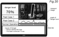
- the display control unit displays a graph representing the time change of the operation result.
- This embodiment makes it easy to identify when the danger level is high or when the operation efficiency is low. In addition, the operator can review the movement before and after that. In addition, the overall trend of whether the danger level, as a whole, tends to be high or whether it was dangerous only at a certain point in time can be seen. The same applies to operating efficiency.
- the information processing apparatus comprising:
- the display control unit associates those corresponding to similar cases among the operation results data, and performs the display in an aspect that can contrast the associated cases.
- Similar cases can be contrasted, and points to be improved, the degree of improvement, and the like can be confirmed.
- Similar cases can be determined, for example, based on the type of suspended load, weight, movement trajectory, and the like.
- the present invention provides a sixth embodiment corresponding to problem (6),
- An information processing apparatus for processing information on transportation by a crane that moves a suspended load within a specified area, comprising: an operation results database that stores, for a plurality of suspended load transport cases, the transport order and the movement trajectory of the lifting device installed horizontally movably for lifting the suspended load; and a transport sequence optimization unit for obtaining a transport sequence in which the transport order of the suspended load is improved so as to improve the predetermined evaluation based on the operation results database.
- the order of carrying a plurality of suspended loads can be optimized, and the carrying efficiency can be improved.
- the evaluation can be, for example, the travel distance of the lifting device.
- the lifting device travels a long distance with the empty load, resulting in waste.
- optimize the carrying order of the suspended load so that the moving distance is shortened.
- the waste of travel distance can be suppressed.
- the evaluation when optimizing is not limited to the travel distance, but various settings are possible.
- the transport sequence optimization unit obtains the transport sequence in consideration of the constraints set in advance on the carrying order of the suspended load.
- the information processing apparatus comprising:
- the optimal path may be obtained only for such a moving trajectory.
- the present invention provides a seventh embodiment corresponding to problem (7),
- An information processing apparatus for processing information related to the operation of a crane that moves a suspended load within a specified area comprising:
- the layout of equipment and obstacles in the facility where the crane is installed can be optimized.
- various "evaluations" for obtaining the optimal layout can be considered.
- the evaluation may be high as the traveling distance of the lifting device is shortened.
- a linear path connecting the departure and arrival points may be transported. If there are equipment or obstacles, which are not fixed, in the facility on this path, a layout that optimizes the transport path of the suspended load will be obtained.
- the optimal layout is determined, the departure and landing place of the suspended load itself may also be changed. If a place is secured so that frequently transported suspended loads can be placed nearby, a layout that is optimal for the transportation route will be obtained. When there is a plurality of hanging loads, these elements may be comprehensively considered to obtain an optimal layout.
- the method for obtaining the optimal path may be either a method using a machine learning or a method obtained analytically without machine learning.
- reinforcement learning with a predetermined "evaluation" as a reward can be used.
- the layout optimization unit obtains the layout in consideration of preset constraints on the movement of the equipment.
- the operation results database stores a transportation route for a plurality of suspended loads
- the layout optimization unit obtains the layout so that the sum of the transportation paths for the plurality of suspended loads is the shortest.
- evaluation of whether the layout is optimal or not can be performed based on various criteria.
- the above embodiment corresponds to the case where evaluation is based on the travel distance of the lifting device. Since shortening the moving distance also leads to a shortening of the carrying time of the suspended load and reducing the burden of the information processing apparatus, an optimal layout effective in many aspects can be obtained according to the above embodiment.
- analytical method can be applied to obtaine the optimal layout.
- the above embodiment is one method thereof.
- the layout optimization unit obtains the layout by reinforcement learning that rewards the predetermined evaluation.
- the above embodiment applies reinforcement learning, which is one of the machine learning, is used to obtain the optimal layout.
- the reinforcement learning in the above embodiment optimizes the layout so that a high "evaluation" can be achieved.
- the layout is optimized so that the moving distance is shortened.
- the present invention provides an eighth embodiment corresponding to problem (8), an information processing apparatus for processing information acquired during the operation of a crane that moves a suspended load within a specified area, comprising:
- Crane accidents can occur due to various factors such as abnormal behavior of suspended loads and operator operation errors.
- an accident such as an operator being caught between the suspended load and the equipment or obstacle may occur.
- the crane is operated alone and an accident occurs, no one may notice it.
- the eighth embodiment makes it possible, by identifying the positional relationship or postures between the suspended load and the people or obstacles around it and determining the occurrence of the accident based on these, to promptly deal with the accident.
- the identification of positional relationships and posture can take various methods described in the third embodiment.
- the method determining the occurrence of an accident may use either a machine learning or a not machine learning as described later. As a method that does not rely on machine learning, a method determining an accident according to a predetermined position relationship or posture can be taken.
- the method for determining the occurrence of an accident emphasizes avoiding an error of judging that an accident has not occurred even though an accident really occurs. This can be improve the reliability of the system.
- various reporting operations may be performed. For example, a mode in which an accident has occurred is notified to the surrounding operators by a loud alarm sound or an alarm lamp, a mode in which an accident occurrence e-mail is sent using a preset address or the like, and the like.
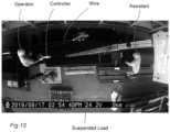
- the accident determination unit determines that an accident has occurred when it detects the appearance of a person who has fallen within a predetermined range from the suspended load.
- a situation in which a person lies down near a suspended load is generally likely to be an accident.
- a camera attached to a lifting device, a laser radar, or the like it is easy to distinguish between a standing person and a person who is lying down with relatively high accuracy. Therefore, according to the above embodiment, accidents can be detected with high accuracy.
- the information processing apparatus comprising:
- the operation results used to determine the occurrence of an accident may be different from those used for generating the learning model. That is, a learning model may be generated based on a separately prepared operation results and applied to an information processing apparatus.
- the accident judgment department notifies the preset recipient when it is judged that an accident has occurred.
- the method for the notification may be a way of sending an e-mail to a preset address, or a way of calling a preset telephone number, notifying the occurrence of an accident by automatic voice. This can shorten the response to accidents. In addition, even if there is no person in the place where the crane is installed, it is possible to deal with the accident.
- the information processing apparatus comprising:
- the image data at the time of the accident may be stored separately from the image database. Further, information specifying the image data at the time of the accident may be stored in the image database, such as storing the time information at the time of occurrence. In this case, the identified image data may be read from the image database and output.
- the output includes both display and providing the image data.
- the present invention when utilizing a learning model, can also be configured as a system for generating a learning model.
- a learning model generation system that generates a learning model for determining the occurrence of an accident during the operation of a crane that moves a suspended load within a specified area, comprising: an operation results database that stores data for identifying the positional relationship and posture between the suspended load and the people or obstacles around it as an operation results; and an accident determination model generation unit that generates a learning model for determining the occurrence of an accident by performing cluster analysis based on the operation results database.
- the present invention further comprises a ninth embodiment corresponding to problem (8), the information processing apparatus comprising: a data acquisition unit, moving with a lifting device which lifts the suspended load and is installed horizontally movably, and acquiring at least one of an image, an infrared ray, and a three-dimensional point cloud; and a security operation unit that drives the lifting device with a preset scanning pattern, determines the presence or absence of an abnormality based on the data acquired by the data acquisition unit during the drive, and executes a preset security operation when an abnormality occurs.
- the crane can be used for an application of abnormality detection other than simply for the transportation of suspended loads. Since the crane is a device that moves upwards and can widely monitor the facility, the application is highly useful.
- the scan pattern described above refers to a preset movement trajectory so that the facility can be uniformly monitored.
- This scanning pattern can be realized by preparing a control device that outputs a control signal so as to move according to such a scanning pattern to the motors of the lifting device.
- the data acquisition unit may be provided according to the type of abnormality to be discovered.
- a camera can be used for acquiring images.
- An infrared camera or an infrared sensor can be used for acquiring infrared rays.
- a laser radar can be used as a device for obtaining a three-dimensional point cloud.
- the security operation in the ninth embodiment may take various operations, such as generating an alarm sound or sending an email to a predetermined address.
- the security operation unit changes the scanning pattern of the lifting device, in case discovering the abnormality.
- the security operation unit determines whether or not a fire has occurred, based on the image or infrared rays, and moves the lifting device to the place where the fire occurs when it is judged that a fire has occurred.
- the lifting device when a fire has occurred, the lifting device is moved to the place of the fire. Therefore, it is possible to continuously monitor the situation of the fire.
- the security operation unit determines the presence or absence of a person based on the data acquired by the data acquisition unit, and moves the lifting device to the entrance and exit of a facility equipped with the lifting device when it is judged that there is a person.
- the above embodiment assumes that it is operated when there is no person, such as after the end of work at the facility.
- Judgment may be made based on an image or a three-dimensional point cloud. It may be judged by infrared rays.
- the system can follow the person enough.
- the moving speed of the lifting device is not as fast as the running speed of the person, so it is difficult to completely follow the person. Therefore, in the above embodiment, when the presence of a person is detected, the lifting device is moved to the doorway. The person is considered to try to exit from the doorway, moving the lifting device to the doorway is possible to take the picture of the person at the time of exit.
- the lifting device When there is a plurality of doorways, the lifting device may be moved so as to sequentially patrol among these doorways. Further, it may be preferentially moved to the doorway closest to the position of the detected person.
- the information processing apparatus comprising:
- the present invention further comprises a tenth embodiment corresponding to problem (9),
- An information processing apparatus for processing information acquired during the operation of a crane that moves a suspended load within a specified area, comprising:
- the lifting point is slightly off the center of gravity, so that the risk that the suspended load swings left and right or back and forth can be suppressed.
- the position information of the lifting device is registered in conjunction with the suspended load.
- the lifting device is moved so as to match the registered position information. In this movement, for example, the registered position information may be read out and the lifting device may be moved to that position, or the operator may visually move it to the vicinity of the suspended load or the like, and the position of the lifting device may be corrected based on the registered position information.
- additional elements may be added in order to accurately lift the center of gravity of the suspended load.
- a wire is usually attached to the suspended load, and this is often hooked to the hook of the crane and lifted, but strictly speaking, depending on how the wire is hooked to the hook, a gap between the lifting position and the center of gravity position of the suspended load is possibly generated.
- a device may be applied to reproduce the attachment position of the wire to the suspended load and the order in which the wires are hooked to the hook. For example, a number or other identification mark may be attached or written at the attachment position of each wire of the suspended load, and the wires may be hooked to the hook in the order specified by the identification mark.
- laser irradiation may be performed on the suspended load from the crane side. Markers corresponding to the spots that are irradiated by the laser are attached to the top surface of the suspended load at the time of landing, or marks are drawn on the upper surface of the hanging. In this way, the next time the suspended load is lifted, if the position of the lifting device is adjusted so that the spot of laser irradiation matches this marker or mark, it is possible to reproduce an appropriate positional relationship with more accuracy.
- the lift off safety support department performs the registration when the hoisting of the lifting device is started after the suspended load is grounded and the wire is detached from the suspended load.
- the lift off safety support department deletes the registered position information when the suspended load is lifted again.
- the position information at the time of landing is registered in order to reproduce the positional relationship between the lifting device and the suspended load that has been landed, and this position information is not useful for reproducing the positional relationship unless it is used for the same suspended load. That is, when the suspended load that has been landed is lifted again, the registered location information is useless. In addition, if such unnecessary position information is used incorrectly, it may not be possible to accurately lift on the center of gravity of the suspended load, which may cause danger.
- the position information that has become useless can be deleted.
- it is possible to suppress the storage capacity for holding unnecessary position information, and to suppress the risk that useless position information is used by mistake.
- the deletion of the registered position information may be performed, for example, based on the operation of the operator. Further, the presence or absence of a suspended load is detected by a method for detecting the load of the lifting device, a method for analyzing the photographed image of a camera attached to the lifting device, or the like, and when it is determined that the suspended load that has been landed has been lifted, the corresponding position information may be automatically deleted.
- Image data can be used in a variety of aspects. For example, when the operator selects any of the registered position information to lift the suspended load that has been landed again, if image data is provided together with the position information, the error in selecting the position information can be suppressed.
- an image is taken with a camera and matched with the registered image data, so that the loading load is correct or false, and the presence or absence of a position shift between the suspended load and the lifting device can be detected. In this way, the reproducibility accuracy of the positional relationship between the suspended load and the lifting device can be further improved.
- the lift off safety support department in case of receiving a lowering instruction to the lifting device in a state where the suspended load is not suspended, corrects the position of the lifting device based on the registered position information within a predetermined range from the lifting device at that time.
- the position of the lifting device is automatically corrected to the position registered corresponding to the suspended load. This makes it possible to save the trouble of selecting the registered position information by the operator. In addition, the risk of selecting an incorrect location information can be suppressed.
- the present invention does not necessarily need to include all of the above-described features, and may optionally omit or combine portions thereof.
- various information processing realized in the above-described information processing apparatus may be configured as an information processing method executed by a computer, or such a method may be configured as a computer program for performing a computer.
- the computer on which the computer program is recorded may be configured as a readable recording medium.
- the present invention will be described with the example of an overhead crane for transporting heavy objects in a factory or warehouse.
- the present invention can be constructed as a variety of information processing apparatus not limited to this example, and can also be configured as a care crane for transporting a person to be cared for, for example.
- the place where the information processing device is installed is not limited to indoors.
- the present invention is applicable not only to those that move using a fixed traveling rail such as an overhead crane as long as it is an information processing apparatus for moving a suspended load within a specified area.
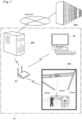
- FIG. 1 is an explanatory diagram showing the embodiment of the information processing apparatus.
- the overhead crane 100 is a device that moves on a traveling rail installed in a factory according to the operation of an operator to transport a heavy object. Its structure will be described later.
- the overhead crane 100 is connected to the information processing apparatus 200 via the wireless LAN 20.
- the information processing apparatus 200 is built by a server as hardware, and various information is acquired and stored in the information processing apparatus 200 during the operation of the overhead crane 100.
- the information processing apparatus 200 performs functions such as analyzing these information and controlling the operation of the overhead crane 100.
- a computer 30 as a terminal is connected to the wireless LAN 20.
- the computer 30 is used for viewing data and analysis results accumulated in the information processing apparatus 200, operation instructions for the overhead crane100, and the like.
- a tablet, a smartphone, or the like may be used as a terminal.
- the information processing apparatus 200 is connected to the learning model generation system 500 via the Internet.
- the learning model generation system 500 is built by a server connected to the Internet as hardware, and plays a role in generating machine learning models used by the information processing apparatus 200 when realizing various functions.
- the learning model generation system 500 is constructed as a separate system from the information processing apparatus 200 in this way, but both may be installed in the same facility, or the learning model generation system 500 may be incorporated into the information processing apparatus 200 and configured as an integrated system.
- the information processing apparatus 200 may be provided by an external server connected via the Internet.
- the information processing apparatus 200 is not necessarily limited to a system composed only of one factory premises.
- FIG. 2 is an explanatory diagram showing the structure of the overhead crane 100.
- the overhead crane 100 is provided with a hoist 120 that corresponds to a lifting device for transporting a suspended load.
- the hoist 120 can lift-up / down the suspended load by winding-up and winding-down the wire 121 to which a hook 122 for hooking the suspended load is attached to the tip.
- Operations of the hoist 120 like winding-up / winding-down of the wire 121, moving and the like can be controlled by a controller 130 connected by a cable 131.
- An enlarged view of the controller 130 is shown in the lower left area of the figure.
- the controller 130 is provided with a pushbutton 132 for power on and off, pushbuttons 133 for winding-up / winding-down the wire 121, and four pushbuttons 134 for moving in four directions, to east, to west, to north and to south.
- the controller 130 is not limited to such schemes.
- the controller instead of the four pushbuttons 134, the controller itself may be rotated around the central axis of the cylindrical housing to indicate the movement direction of the hoist 120.
- the controller 130 may use a wireless one instead of a wired one connected by a cable 131.
- a camera 124 is attached to the hoist 120.
- the camera 124 is for capturing moving images and is fixed downward so that vertical downward direction can be captured.
- a still camera for taking a still image may be used for the camera 124, instead.
- the captured image data is transmitted to the information processing apparatus 200 via the wireless LAN 20 described in FIG 1 .
- the hoist 120 also has a laser radar 125.
- the laser radar 125 is a device that irradiates a laser from the main body and measures the distance to the person or object based on the time until it hits the surrounding person or object and reflects it. By scanning the laser within a certain range, the shape and distance of surrounding people and objects can be obtained in the form of a three-dimensional point cloud.
- the laser radar 125 was mounted downward so as to obtain a three-dimensional point cloud below the hoist 120. The obtained three-dimensional point cloud is transmitted to the information processing apparatus 200 via the wireless LAN 20.
- the hoist 120 has a display 123 attached to it facing downwards.
- a liquid crystal display is used in this embodiment, but an organic EL, an LED or other display or indicator can be used as the display 123.
- the display 123 displays useful information such as the movement direction of the hoist 120 to the operator or the like during the operation of the crane.
- a camera to capture the screen of the display 123 may be further attached to the hoist 120.
- the camera 124 is also usable as a camera to capture the display 123.
- the running rails 101 and 102 are laid parallelly and horizontally near the ceiling of its building.
- Saddles 111 and 112 are attached on the running rails 101 and 102 so that they can travel like arrow a by motor power.
- the saddles 111 and 112 are fixed to the crane girder 110 straddling both.
- the crane girder 110 is provided in a horizontally and orthogonal to the traveling rails 101 and 102. When the saddles 111 and 112 move in the direction of the arrow a, the crane girder 110 can also move as an integral part therewith.
- the hoist 120 is attached to the crane girder 110 so that it can be moved by a motor along the crane girder 110 in the direction of arrow b.
- the hoist 120 can arbitrarily move the space between the traveling rails 101 and 102.
- a mechanism for detecting the position of the hoist 120 is provided.
- a marker 103 for detecting a position is drawn on the running rail 102.
- the crane girder 110 also depicts a marker 114 for position detection.
- the hoist 120 is moving, the amount of movement of the hoist 120, and thus the position of the hoist 120 in the b direction can be detected by optically reading the marker 114 by the sensor 127 fixed to the hoist 120.
- the sensors 113 and 127 it is possible to detect the horizontal position coordinates (x, y) of the hoist 120.
- the position coordinates are transmitted to the information processing apparatus 200 via the wireless LAN 20.
- FIG. 3 is an explanatory diagram showing an embodiment of a position detection mechanism.
- a mechanism for detecting the position in the a direction of the saddle 112, that is, the X coordinate in FIG. 2 has been shown.
- the right direction is the positive direction of the X coordinate and the left direction is the negative direction.
- the origin can be set at any location.
- the marker 103 described in FIG. 2 is depicted on the traveling rail 120. As specifically shown in FIG. 3 , the marker 103 includes a position detection marker 103a and a coordinate detection marker 103b.
- the position detection marker 103a alternately depicts white and black regions.
- the width wb of the black area is constant.
- the width ww of the white area is also constant. Both wb and ww may be the same width or may be different.
- the position detection marker 103a is depicted throughout the traveling rail 120. In this embodiment, a tape depicting the pattern illustrated in advance was prepared and affixed to the running rail 120.
- the coordinate detection marker 103b is a short marker drawn at an appropriate position on the traveling rail 120. It may be provided in one place of the running rail 120, or may be provided in a plurality of places.
- the coordinate detection marker 103b is formed in a white and black region, but the number and width are different for each location. That is, a single pattern composed of the number and width of white and black lines identically represents a specific position of the running rail 120.
- the position detection mechanism includes optical sensors 113a, 113b for detecting the position detection marker 103a and the optical sensor 113c for detecting the coordinate detection marker 103b.
- the optical sensors 113a and 113b are installed at a staggered phase with respect to the traveling direction. Therefore, when moving to the right side, the optical sensor 113a detects a black and white pattern, and then the optical sensor 113b detects a black and white pattern with a slight delay. Conversely, when moving to the left side, the optical sensor 113b detects a black and white pattern, and then the optical sensor 113a detects a black and white pattern with a slight delay.
- the optical sensor 113a and 113b detects a black and white pattern with a slight delay.
- a method for identifying the X coordinate of the hoist 120 by the position detection mechanism is as follows.
- Nbxwb + Nwxww is added to the previous coordinate value.
- Nbxwb + Nw ⁇ ww is subtracted from the previous coordinate value.
- the optical sensors 113a and 113b are installed with phase differences, there are 4 states of the output of both, that is, (1) both optical sensor 113a and 113b are black, (2) the optical sensor 113a is black, the optical sensor 113b is white, (3) optical sensors 113a and 113b are both white, (4) the optical sensor 113a is white, and the light 113b is black, and these 4 states are periodically output within the wb + ww section. Therefore, according to these four outputs, the position identification can be a higher resolution than the width wb of the black area and the width ww of the white area.
- the pattern can be specified based on the number and width of the black and white regions, and the X coordinate value can be specified by referring to the pre-stored pattern information. Since the coordinate value calculated with the position detection marker 103a may include an error, when the coordinate value is specified by the coordinate detection marker 103b, the coordinate value calculated with the position detection marker 103a can be corrected by this value. This way can improve the accuracy of position detection.
- Location information detection may be executed by other methods.
- preparing a database storing the position of the equipment and the like in the facility in advance obtaining the relative positional relationship with the equipment or the like through analyzing the lower image taken by the camera 124, and detecting the position coordinates of the camera 124 and the position coordinates of the hoist 120 may be executed.
- a marker having a predetermined shape that is easy to detect may be used instead of equipment.
- the laser radar 125 measuring the distance to the wall around the facility, thereby calculating the position relative to the wall by the measurement, and detecting the position coordinates of the hoist 120 can be taken.
- a laser ranging device for measuring the distance to the surroundings may be separately attached to the hoist 120.
- radio waves can be received well in the facility, it is also useful to use GPS in combination.
- FIG. 4 is an explanatory diagram showing the embodiment of the information processing apparatus 200 and the learning model generation system 500.
- the information processing apparatus 200 and the learning model generation system 500 are configured, as hardware, by a computer having a CPU and a memory, particularly a server, and each functional unit shown in the illustration is constructed in software. Some or all of these functional units may be built in hardware.
- the operation results database 201 is a database storing various information during operation of the overhead crane 100.
- the data to be stored includes position coordinates of the hoist 120, operation data of the controller, working data such as the type of suspended load and the transport schedule, and the like.
- Position coordinates, operation data, and the like are stored in a time series by associating each data with the time information obtained.
- the position coordinates and operation data are stored separately. A method of sequentially storing each time, position coordinates, and operation data as a set of data may be used.
- the advantage in this method is that the relationship between the position coordinates and the operation are easily collated, but for example, during the operation of lifting and downing the load, the same position coordinates are stored repeatedly even though the hoist 120 does not move, thus a wasteful amount of data is likely to occur.
- the data storage format may be selected by comprehensively considering such merits and demerits.
- operation result data data stored in the operation results database 201 may be collectively referred to as "operation result data”.
- the three-dimensional point cloud database 202 stores data of the three-dimensional point cloud obtained by the laser radar 125.
- the three-dimensional point cloud data is repeatedly acquired at predetermined time intervals and is stored in the three-dimensional point cloud database 202 in association with the acquired time.
- the image database 203 stores image data obtained by the camera 124.
- the image data is a moving image.
- Image data is also stored in a form in which each scene is correlated with the time.
- the incident database 204 stores information that identifies the time and position coordinates when an abnormality is detected in the facility where the crane is installed, and the three-dimensional point cloud data and image data before and after that.
- the crane in this embodiment has a function of monitoring the facility in an unmanned state in addition to normal operation for transporting suspended loads. In addition, during normal operation, it has a function to determine whether or not an accident has occurred.
- "Abnormality" stored in the incident database 204 means an abnormality discovered by the surveillance, specifically a fire and a suspicious person, and also an accident.
- the incident database 204 stores information that identifies three-dimensional point cloud data and image data during periods of time before and after the occurrence of abnormalities.
- the basic operation database 205 stores image data representing the basic operation to be performed by the operator during the operation of the crane. This data can be used to determine whether or not the operator performed these basic operations during operation. It can also be used to teach the operator the basic operation that should be performed originally. In this embodiment, in order to use the judgment, a moving image taken from the top to downward in the same manner as the camera 124 was used for the basic operation. As data for teaching the operator, an image taken from the front of a person may be prepared. Note that each image data is stored in conjunction with the name of the basic operation to be performed by the operator.
- the crane movement control unit 210 performs a function of controlling the movement of the crane. In the normal operating state of the crane transporting the suspended load, the operator is mainly moved by the operation of the controller 130 (see FIG. 1 ). However, in this embodiment, in addition to this, the crane can move unmanned in the facility in a predetermined scanning pattern and monitor the presence or absence of abnormalities.
- the crane movement control unit 210 controls the movement of the crane for this monitoring.
- a scanning pattern for example, is executed by main scanning, crane running in the a direction from one end of the running rails 101 and 102 in FIG.
- the main scan may be performed in the b direction and the secondary scan may be performed in the a direction.
- These scans can be used not only for monitoring but also to obtain images of the entire floor of the facility where the crane is installed. That is, in the above-described scanning pattern, the image taken by the camera 124 may be merged.
- Various well-known techniques can be applied to the method of merging a plurality of images while aligning them with each other. Since there are people and the like other than fixed objects such as equipment and obstacles in the facility, images in which people are not captured preferably are selected and merged. By using the images obtained by scanning at different time zones, even if an image in which a person is shown, an image that can sufficiently represent the floor surface can be obtained.
- the position detection unit 211 detects the position coordinates of the hoist 120 during the operation of the crane.
- the detection method is as described in FIG 1 .
- the position detection unit 211 receives data transmitted from the overhead crane 100 and obtains the position coordinates based on the data.
- the obtained position coordinates are stored in the operation result database 201.
- the position coordinates are periodically detected with a certain period.
- the position detection unit 211 temporarily accumulates position coordinates for a certain period and stores the acquired data in the operation result database 201 for the interval judged to be moving linearly at an almost constant speed. By doing this, the amount of data in the position coordinates can be reduced.
- the data acquisition unit 212 performs a function of acquiring various data from the overhead crane 100.
- the acquired data may include image data taken by the camera 124, three-dimensional point cloud data obtained by the laser radar 125, operations on the controller 130, and the like.
- the acquired data is stored in the operation results database 201.
- the maintenance timing judgment unit 220 determines the necessity of crane maintenance and the maintenance period based on the operation result data stored in the operation results database 201. When machine learning is used for these judgments, the maintenance timing judgement unit 220 holds a learning model generated by the learning model generation system 500 and makes a judgment using this. Examples of the maintenance judgment target include a motor for moving the hoist 120, the motor for winding-up / winding-down, the wire 121, the controller 130, and the like.
- the basic operation judgment unit 221 determines whether or not the operator performed a predetermined basic operation while the crane is in operation. In the present embodiment, a judgment is made based on comparing the image data taken by the camera 124 to the basic operation database 205. From the three-dimensional point cloud obtained by the laser radar 125, only the point cloud of a person may be extracted, and it may be determined whether or not the basic operation is performed based on this. Comparing image data or three-dimensional point cloud data to the basic operation database 205 can be done by pattern matching, but machine learning is more effective. When machine learning is used, the basic operation judgement unit 221 holds a learning model generated by the learning model generation system 500 and makes a judgment using this.
- the statistical processing unit 222 performs various statistical processes related to the operation of the crane. Examples of the statistical processing include the calculation of the operation time of the information processing apparatus, the total transport time of the suspended load, the average transport time, the total moving distance, the average moving distance, the total time or the average value required for lifting and lowering the load, and the aggregation of the number of controller operations. In addition to statistical processing on a daily basis, statistical processing on a weekly or monthly basis may be performed, or processing such as a comparison by day, week, or month may be performed.
- the results of statistical processing can be used to determine maintenance timing, operation diagnosis, and the like.
- the results of statistical processing may also be stored in the operation result database 201.
- the hazard assessment unit 223 evaluates the presence or absence of danger and the extent thereof during and after the crane is in operation.
- a series of operations for transporting the suspended load are divided into scenes, such as attaching wires to the suspended load, lifting, starting transportation, transporting, unloading, and removing wires, and the danger is evaluated for each scene.
- the hazard assessment is based on the positional relationship between the suspended load and people, equipment, etc.
- the hazard assessment unit 223 holds a learning model generated by the learning model generation system 500 and makes a judgment using this.
- the accident determination unit 224 determines whether or not an accident has occurred while the crane is in operation. In this embodiment, this judgement is performed based on the positional relationship between the load and people, equipment, the posture of the person, and the like.
- the hazard assessment unit 223 holds a learning model generated by the learning model generation system 500 and makes a judgment using this.
- the security operation unit 225 performs unmanned monitoring in the facility by a crane, and when an abnormality is found, it performs a function of dealing with it. Abnormalities include fires and the discovery of suspicious persons. Dealing include changing the crane's scanning pattern and reporting.
- the operation diagnosis unit 230 performs a function of diagnosing the operation of the crane after the operation of the crane. Diagnosis contents include the presence and absence of danger and its extent, and operation efficiency.
- the transport sequence optimization unit 231 provides a result of optimizing the carrying order of the suspended load by the crane. When transporting multiple suspended loads, depending on the order, the distance that the crane travels with the empty load becomes longer and waste occurs. The transport sequence optimization unit 231 optimizes the carrying order of the suspended load so that the moving distance travel distance in the empty load is shortened.
- the optimal route setting unit 233 provides an optimal path that optimizes the transport path of the suspended load by the crane. For example, when transporting a suspended load from point A to point B, a straight line connecting the two points is the shortest travel distance, that is, the optimal path. In this example, the optimal path is obtained in this way based on various constraint conditions.
- the layout optimization unit 234 optimizes the layout of equipment and obstacles in the facility where the crane is installed.
- the shortest carrying path of a suspended load is a linear path connecting the departure and arrival points.
- the layout optimization unit 234 provides a layout, for example, in which equipment or obstacles on the path are moved to achieve the shortest carrying path.
- changes to the origin and arrival of the suspended load itself will be considered.
- the display control unit 232 displays the outputs in the various functions described above on the screen of the computer 30 connected to the information processing apparatus 200. It may be displayed on the display 123 attached to the crane. The image may change depending on each function.
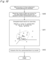
- the image-in-hazard provision unit 235 provides image data and three-dimensional point cloud data between predetermined periods before and after the occurrence of the abnormality. Specifically, the storage location of the image data corresponding to the specified abnormality is specified by referring to the incident database 204, and these are read from the image database 203 or the three-dimensional point cloud database 202. In addition to displaying on the screen of the computer 30, a method of outputting to a recording medium or the like as a series of moving image data can be taken.
- the lift-off safety support unit 250 performs a function to support the improvement of safety at the moment when the suspended load leaves the floor surface, that is, at the moment of lift-off.
- the crane accurately lifts the center of gravity of the suspended load, the suspended load is lifted off almost without shaking as the crane is hoisted, but if the lifting position is slightly off from the center of gravity, the suspended load may swing forward, backward, left, and right at the moment of the lift-off.
- an accident such as an operator colliding with a suspended load may occur.
- the lift-off safety support unit 250 records the position of the crane when the suspended load is placed on the floor, and when the suspended load is lifted again, it accurately reproduces the position. By doing this, the crane can accurately lift the center of gravity of the suspended load.
- the lift-off safety support unit 250 also realizes a function of managing a stored position, various functions for accurately reproducing the center of gravity position, and a function for improving convenience for position registration or reproduction. Of course, some of these features can be omitted.
- the transmission / reception unit 240 exchanges data with the overhead crane 100, the computer 30, the learning model generation system 500, and the like via the wireless LAN 20 and the Internet.
- the transmission / reception unit 240 also provides a function as an input unit that accepts commands from the computer 30 to the information processing apparatus 200 in the setting of the optimal path, optimal sequence, optimal layout, and the like.
- the learning model generation system 500 generates learning models used in various functions of the information processing apparatus 200 by machine learning and provides them to the information processing apparatus 200. In the present embodiment, it is constructed as a separate system from the information processing apparatus 200, but may be integrated into the information processing apparatus 200.
- the learning model generation system 500 can also be a system for generating a general-purpose learning model common to a plurality of cranes.
- the operation results database 501, the three-dimensional point cloud database 502, and the image database 503 correspond to the operation results database 201, the three-dimensional point cloud database 202, and the image database 203 in the information processing apparatus 200, respectively.
- each database of the information processing apparatus 200 is appropriately copied to the learning model generation system 500 and updated. If machine learning is performed repeatedly by using these database, it is possible to perform re-learning reflecting the crane operation results, and to improve the accuracy of the learning model.
- the contents of the operation results database 501, the three-dimensional point cloud database 502, and the image database 503 may differ from each database in the information processing apparatus 200 in consideration of the generation of the learning model. For example, data unnecessary for machine learning described below may be omitted. Further, the judgment result made using the learning model in the information processing apparatus 200 may be stored as one of the operation result data.
- the transmission / reception unit 540 exchanges data with the information processing apparatus 200 via the Internet.
- the data to be exchanged includes operation result data and other data stored in each database, and a learning model.
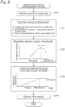
- the learning data generation unit 510 generates data for machine learning based on each data stored in the operation results database 501, the three-dimensional point cloud database 502, and the image database 503. For example, it generates operation results data from the start of the operation until the crane starts moving based on the time at which the controller operation is performed and the position information of the hoist 120. In addition, various data will be generated depending on the way of machine learning.
- the maintenance timing judgement model generation unit 521 generates a learning model for determining the maintenance period of the crane. Examples of the maintenance judgment target include a motor for moving the hoist 120, a motor for winding-up / down, a wire 121, a controller 130, and the like. The maintenance timing judgement model generation unit 521 may generate a learning model for each of these subjects.
- the hazard assessment model generation unit 522 generates a learning model for evaluating the presence or absence of danger and the degree thereof with respect to the operation status of the crane.
- training data indicating the presence or absence of danger and the degree thereof are prepared for various situations, and supervised machine learning based on this data is used. Other methods may be used.
- the accident determination model generation unit 523 generates a learning model for determining whether or not an accident has occurred while the crane is operating.
- supervised machine learning is used. Other methods may be used.
- the basic operation determination learning model generation unit 520 generates a learning model for determining whether or not the operator performed a predetermined basic operation while the crane was in operation.
- image data when the original basic operation is performed and image data when these basic operations are not performed are prepared in the basic operation database 505, and machine learning classification is performed using these data as training data.
- the image of the basic operation database 505 is based on a moving image taken from the top to downward by the camera 124, and is made into a series of still images for each frame, and only the target human part is cut out from each still image data.
- the information processing apparatus 200 and the learning model generation system 500 provide various functions described later by the function units described above.
- the embodiment of the functional unit described in FIG. 4 is only an example, and functional parts other than these may be prepared, or the functional parts shown here may be divided into a plurality of functional parts, or a plurality of functional parts may be integrated.
- FIG. 5 is a flowchart of the trajectory display process. This process is mainly performed by the position detection unit 211 and the display control unit 232 shown in FIG. 4 using the operation result data stored in the operation result database 201, and in hardware, this process is executed by the CPU of the information processing apparatus 200.
- the information processing apparatus 200 inputs a designation of the date and time of display target (step S10). These are instructed by a terminal such as a computer 30.
- a terminal such as a computer 30.
- the movement trajectory for the corresponding date is displayed.
- the start date and time and the end date and time are specified, the movement trajectory of the corresponding period is displayed. It is useful when it is demanded to see the movement trajectory of a specific time zone in the day.
- the movement trajectory of the corresponding dates are displayed. It is useful when these movement trajectories are contrasted with each other.
- Various other aspects of the date and time designation may be prepared.
- the information processing apparatus 200 reads the corresponding operation result data and image data (step S11).
- a statistic data is calculated using these data.
- the travel distance which is the moving distance in the direction of rail 101 and 102 the transverse distance which is the moving distance in the direction of the crane girder 110, the number of operation times of the controller pushbutton, the carrying distance of the suspended load, the crane operation time, and the like are obtained. Other statistical processing may be performed.
- the information processing apparatus 200 uses these data to display the movement trajectory according to the display mode (step S13).
- the display mode may include a mode displaying only the movement trajectory, a mode displaying image data together with the movement trajectory, and the like.
- the information processing apparatus 200 displays the movement trajeotory again according to the instruction (step S13). Further, when a change in the display target date and time is instructed (step S15), the process after step S10 is executed again.
- the trajectory display process ends.
- the information processing apparatus 200 displays a movement trajectory at a specified date and time.
- FIG. 6 is an explanatory diagram showing an example (1) of the trajectory display screen.
- the target display time setting (d11) is displayed, and the corresponding movement trajectory (d14) is displayed.
- a movement trajectory is a straight line or curve that connects the position information of the time series in which the crane has moved in the facility.
- the dashed line shows the movement trajectory with the empty load
- the solid line shows the movement trajectory in the state of carrying the suspended load.
- a button d12 for indicating the display of statistical data is provided on the upper right portion.
- statistical data d17 such as travel distance and the like is displayed.
- the movement trajectory can be displayed as a moving image.
- the moving image may be an embodiment in which a symbol representing a crane moves on a moving trajectory, for example. Further, a moving trajectory may be drawn according to the movement of the crane.
- FIG. 7 is an explanatory diagram showing an example (2) of the trajectory display screen.
- a movement trajectory is displayed in the region d21, and a symbol d23 representing a crane moves along the movement trajectory. Further, an image corresponding to the position of the symbol d23 is displayed in the region d22. According to this display mode, the state of the crane during movement can be easily confirmed in the image.
- the display of the movement trajectory can take various embodiments in addition to those shown in FIGS. 6 and 7 .
- the crane user can visually grasp the crane operation results.
- FIG. 8 is a flowchart of the maintenance timing determination process. It is mainly a process performed by the maintenance timing judgment unit 220 shown in FIG. 4 , using the operation result data stored in the operation result database 201, and in hardware, it is a process executed by the CPU of the information processing apparatus 200.
- the information processing apparatus 200 reads the operation result data (step S20) and generates various cumulative data since the previous maintenance (step S21).
- Maintenance may include periodic inspections. The reason why it was decided to do so after maintenance is because it is considered that crane malfunctions and the like have been resolved by maintenance. However, since not all parts are replaced in maintenance, for parts that are not subject to maintenance, cumulative data since the maintenance for which the relevant part was targeted in the previous time may be generated.
- These maintenance results may be stored together with the operation result data.
- the image data may also be stored in connection with the operation content of the controller or the operation of the crane. By doing this, it can be utilized for detecting abnormalities in the indicator. Further, when a wireless controller is used, the battery charge history and the like may be stored as maintenance results. In this way, it can be used to predict battery drain.
- Examples of the cumulative data include the number of times the controller pushbutton is operated, the traveling distance / transversal distance of the crane, the carrying distance of the suspended load, and the like. Other cumulative data may be generated.
- the information processing apparatus 200 reads the determination threshold for determining whether or not maintenance is required (step S22).
- the method for setting the judgment threshold is shown in the figure. For example, consider the case where the maintenance time of the pushbutton of the controller is determined. By taking the number of operation times on the horizontal axis and the number of failures on the vertical axis, the past results may give the distribution as shown in the figure.
- “number of cases” does not mean the number of times a failure has occurred in one controller, but in the past performance, that the number of failures is n that failure occurred in the N-th operation, and the number of failures is m that failure occurred in the M-th operation, and so on.
- the distribution of the number of failures obtained in this way can determine the mean value and the standard deviation.
- the judgment threshold may be set by "mean value - coefficient x standard deviation".
- the coefficient can be 3 to 5.
- the determination threshold is a value set in advance by such a method.
- the determination threshold may be set for each target for determining the maintenance period, such as a controller, motor, or indicator. Note that the above-described method is only an example of setting the determination threshold, and the determination threshold can be arbitrarily set.
- the drain of the battery may also be subject to determination.
- the radio controller it is necessary to avoid a state that becomes uncontrollable due to battery drain while the crane is operating, so even if the remaining battery capacity decreases, it is necessary to operate it until there is no danger, such as landing the suspended load or moving the crane to the standby position. Therefore, it is preferable to set the determination threshold for the battery within a range that can secure the remaining amount that can be operated.
- the information processing apparatus 200 predicts the maintenance period by comparing the cumulative data to the determination threshold (step S23). If the cumulative data has already exceeded the judgment threshold, it will be judged that maintenance is necessary promptly. Prediction of the maintenance period when the cumulative data does not exceed the judgment threshold can be performed by various methods. An example is shown in the figure. Take the elapsed time since the previous maintenance on the horizontal axis and the number of operations on the vertical axis. The line connecting the origin with the point corresponding to the current elapsed time and the number of operations is extended to obtain the time at which the number of operations reaches the judgment threshold. By doing this, when a threshold will be reached if the number of operations increases can be predicted, and the maintenance time can be predicted with the same trend as the present.
- the information processing apparatus 200 performs the above-described determination process for each maintenance judgment target.
- the judgment method may be changed for each judgment object. Further, the prediction of the maintenance period may be made using a method other method than that described above.
- the information processing apparatus 200 outputs the result thus obtained (step S24) and ends the maintenance timing determination process.
- a screen display to the computer 30, an email to the person in charge, or the like can be taken.
- the cumulative data has already exceeded the judgment threshold and it is judged that prompt maintenance is necessary, it may be displayed on the crane display 123 or other alarms.
- Machine learning may be used to determine the maintenance period.
- machine learning may be used to determine the maintenance period.
- FIG. 9 is a flowchart of data generation process for determining the maintenance period. It is a process that generates data for machine learning based on data stored as operation results. It is mainly a process performed by the learning data generation unit 510 shown in FIG. 4 , and in hardware, it is a process executed by the CPU of the learning model generation system 500.
- the learning model generation system 500 reads the operation result data from the operation result database 501 (step S30) and generates motor operation status data (step S31).
- the contents of data generation are shown in the figure.
- the graph above shows the on/off state of the controller pushbutton.
- pushbuttons There are a plurality of pushbuttons, but only one of them is shown here as an example.
- the crane moves while the pushbutton is turned on.
- the middle graph shows the current of the motor. After turning on the pushbutton, current starts to flow to the motor after the time td elapses. Thereafter, the current flows until the pushbutton is turned off with changing slightly due to noise.
- the motor current suddenly drops in the period ti0 and ti1 during the period top in which the pushbutton is turned.
- the bottom graph shows the change in the crane's moving speed. After the operation of the pushbutton, according to the current change of the motor, the crane moves. Where the motor current falls, the crane's travel speed is similarly reduced. From the average speed of the crane, the average speed of the crane is obtained.
- step S31 as data for determining the necessity and timing of maintenance of the motor and the pushbutton, the time interval top in which the pushbutton is turned on, the time td until the motor current rises, the time ti0 and ti1 at which the motor current drops, the average speed of the crane, and the like are generated.
- various other data may be generated depending on the way of machine learning.
- the learning model generation system 500 generates data on the loading situation (step S32).
- the contents of data generation are shown in the figure.
- On the left is the relationship between the hoisting amount of the crane and the height of the suspended load.
- the height of the suspended load rises proportionally.
- the slope of this graph may become declines or deviates from the straight line.
- the right side of the figure shows the height change of the suspended load during transportation.
- the height of the suspended load maintains an almost constant while slightly vibrating up and down.
- the elastic force decreasing the frequency of this vibration decreases, and a tendency to increase the amplitude may appear.
- the amplitude and frequency are calculated for the vibration of the suspended load height during crane transport as data for determining the maintenance period of the wire 121.
- various other data may be generated depending on the way of machine learning.
- a camera may be attached to the helmet of the operator, and data for machine learning may be generated by photographing the suspended load and analyzing the situation as an image. Data such as the height and vibration of the suspended load may be acquired, or the angle of the wire and its change when the load is suspended may be acquired.
- the display based on the image of the display, the presence or absence of display defects, the quantity, the presence or absence of flickering of the display, the degree of flickering, and the like can be quantified to obtain data for machine learning.
- FIG. 10 is a flowchart of a maintenance timing judgement model generation process. It is a process mainly performed by the maintenance timing judgement model generation unit 521 shown in FIG. 4 , and in hardware, it is a process executed by the CPU of the learning model generation system 500. In this embodiment, unsupervised machine learning is used.
- the learning model generation system 500 reads the training data generated by the data generation process for determining the maintenance period (step S40).
- unsupervised machine learning is performed based on these training data (step S41). Specifically, a cluster of training data is generated for each of the pushbuttons, motors, and wires that are subject to determination of the maintenance period.
- the training data related to the operation of the pushbutton includes a time interval top in which the pushbutton is turned on, a time td until the motor current rises, a time ti0 and ti1 in which the motor current drops, and the average speed of the crane.
- the area where the training data is concentrated is considered to represent the normal state.
- data that deviates from this concentrated area can be said to be in a state where abnormalities are occurring, that is, in a state requiring maintenance. Therefore, if a learning model is generated to recognize a region considered normal as a cluster based on the training data, it can be used for the necessity of maintenance.
- the data indicated by the white circles represent the training data in the normal state.
- the data represented by the x represents the training data of the abnormal state.
- Generating clusters corresponds to the process of generating a learning model that determines the area of dashed lines in the figure.
- the cluster is represented by, for example, its central CG and the distance R. When the training data to be determined exceeds the distance R from the central CG, it is judged to be outside the cluster and maintenance is judged to be necessary.
- the training data is represented in a three-dimensional space, but the dimensions of this space vary depending on the type and number of training data.
- the learning model generation system 500 outputs the thus generated learning model, that is, the maintenance time determination model (step S42), and ends the maintenance time judgment model generation process.
- FIG. 11 is a flowchart of a maintenance timing determination process as a modification example. It is a process mainly performed by the maintenance timing judgment unit 220 shown in FIG. 4 using the operation result data stored in the operation result database 201, and in hardware, it is a process executed by the CPU of the information processing apparatus 200.
- the information processing apparatus 200 reads the operation result data (step S50) and executes the data generation process for the maintenance timing determination process (step S51).
- the process contents are as described with reference to FIG 9 .
- the same processing as the one performed when generating the learning model is executed.
- the information processing apparatus 200 calculates the distance DC from the cluster center using a pre-generated maintenance timing judgement model (step S52).
- the image is shown in the figure.
- the learning model gives the center CG of the cluster and its distance R whose operation performance is judged to be "normal”. Therefore, in order to determine whether or not the operation performance exists in the cluster, the distance DC is calculated.
- step S53 If the calculated distance DC is greater than the distance R to the boundary of the cluster (step S53), it means that the operation performance is out of normal. Therefore, the information processing apparatus 200 determines that maintenance is necessary and notifies that (step S54). Notification can be made in a variety of ways.
- step S55 the timing of maintenance is predicted. As shown in the figure, by extending the elapsed time since the previous maintenance and the distance DC at the present time, the time at which this reaches the distance R is obtained, and this is referred to as the maintenance timing.
- the information processing apparatus 200 notifies the maintenance timing thus predicted (step S56).
- the maintenance period prediction method and the notification method can be taken in various other ways.
- the maintenance period can be determined before the crane is subject to periodic inspection, and it is possible to avoid failure at an early stage.
- FIG. 12 is a flowchart of the hazard assessment process. It is a process mainly performed by the hazard assessment unit 223 and the basic operation judgment unit 221 shown in FIG. 4 , and in hardware, it is a process executed by the CPU of the information processing apparatus 200. This process is performed after the operation of the crane to determine the presence or absence of danger and the degree thereof based on operation result data, three-dimensional point cloud data, and image data.
- the posture of the operator may be easily identified by attaching a sensor to the operator's helmet, glove, work clothes, etc., or by affixing a characteristic marker for facilitating recognition by image analysis.
- danger level means an index for representing the presence or absence of danger and the degree thereof.
- the information processing apparatus 200 determines which transport scene corresponds to the operation results of evaluating the presence or absence of danger or the like (step S60).
- it is divided into six scenes before lifting the suspended load, during lifting, starting transportation, transporting suspended load, unloading, and after unload.
- hoisting it may be subdivided into lift-offing, and after lift-offing.
- status data indicating which of these scenes is corresponded to is stored as operation result data, it can be easily determined based on the status data. Even if status data is not used, it is possible to make a judgment based on the position information of the crane, the information of lifting-up / lifting-down, and whether or not the crane is carrying the suspended load.
- the state after the crane moves with an empty load and stops is judged to be before lifting the suspended load.
- the state during hoisting is judged to be during lifting of the load.
- winding is completed, it is judged that the transportation starts.
- the crane starts moving it is judged to be in transporting.
- the crane stops and starts unwinding it is judged to be unloading.
- winding is completed, it is judged that it is after unload. It is possible to judge the scene in various other ways.
- the presence or absence of a suspended load or the like may be analyzed using image data or three-dimensional point cloud data to determine the transport scene.
- the information processing apparatus 200 evaluates the presence or absence of danger and the degree thereof by the following processing for each scene.
- the information processing apparatus 200 detects the suspended load shape, the position of the wire, the position of the crane, and the like (step S61). These detections can be performed by analysis of three-dimensional point cloud data and image data. While the image data is planar and is difficult to specify the distance from the camera 124 to the object, the three-dimensional point cloud data is useful for this analysis because the position can be obtained three-dimensionally.
- a camera may be attached to the operator's helmet, and the analysis result based on the image data taken by the camera may be used. The camera can capture the angle of the wire, the elongation of the wire, and the rotation and the vibration of the load, etc. when lifting the load.
- the information processing apparatus 200 calculates the danger level based on the standard positional relationship and determines the reason (step S62).
- the standard positional relationship for judging the danger level is set in advance for each transport scene as shown below.
- the procedure until attaching the wire to the suspended load is targeted.
- predetermined items for determining danger like:
- a positional relationship characteristic of each item can be used as a standard positional relationship.
- FIG. 13 is an explanatory diagram showing a scene example before lifting. It shows that an operator is working with the controller in his hand at one end of the suspended load, and there is another operator at the other end.
- the suspended load is hung with wires.
- By analyzing the image data or the three-dimensional point cloud data of this scene it is possible to obtain the positional relationship of the operator, another operator, the load, the wire, and the like. Then, based on the positional relationship between the suspended load and the wire, it can be determined whether item b) is satisfied or not. In addition, since it can be confirmed that the operator is covering over the suspended load, it is judged that the item c) of wire inspection is conducted.
- the risk level for each item is set in advance as an indicator.
- the danger level may be set to 100 (%), and for items with a low degree of impact, the danger level may be set to 50 (%).
- the danger level can be set arbitrarily, but may be set based on, for example, the probability that an accident occurs when the item is not performed based on the past cases. Further, the danger level does not necessarily need to be expressed in %, and may be expressed by some kind of score or the like.
- step S62 based on the detected positional relationship and the like, the danger level is determined to what extent the positional relationship of the above-described criteria is satisfied. For example, when the danger level of item a) is set to the value A (%), and when the positional relationship corresponding to this item is satisfied, the danger level is 0 (%), but when it is not satisfied at all, the danger level is A (%). In the meantime, the danger level is calculated by the A x coefficient according to the degree of satisfaction.
- the overall danger level is calculated based on the average value or maximum value of the obtained hazard.
- the item that becomes the maximum danger level has a large influence on the overall danger level. Therefore, the content of the item can be selected as a "reason" for the danger level.
- the hoisting speed of the crane during lifting-up the load may be considered. Since there is a predetermined recommended value or an upper limit value for the winding speed, the danger level becomes high when this is exceeded. From this point of view, it may be used to determine the danger level based on the winding speed.
- the information processing apparatus 200 outputs the danger level and reason obtained by the above processing as a result (step S69), and ends the hazard assessment process.
- the result output can take an aspect of displaying the danger level, the reason, and the corresponding image data as shown in FIG 20 . This display will be described in detail later.
- the danger level evaluation result may be stored by adding it to the operation result data.
- the shape, positional relationship, and the like to be detected in step S61 are for determining the positional relationship of the above-described criteria. Therefore, the content to be detected may be determined based on the positional relationship of the criteria before and during lifting, respectively. The contents to be detected in step S61 may be different in each transport scene before and during lifting.
- the hazard assessment process was described as being performed after the operation based on operation result data, but it may be performed in real time as much as possible while the crane is in operation.
- an alarm may be output as a result output (step S69).
- alarming for example, a method of displaying a warning to the crane display 123, a method of sounding an alarm sound at the site during operation, a method of notifying the administrator by e-mail or the like, and the like can be taken.
- step S60 the process when the transport scene is determined as a transportation start.
- the information processing apparatus 200 detects the positional relationship between the suspended load and the operator and surrounding obstacles, and detects whether or not basic operations have been conducted (step S63).
- step S64 the reason is created (step S64), and the result is output (step S69).
- the positional relationship and the danger level of the reference can be set, and the danger level for each item can be calculated by the same method as described in step S62.
- the basic operation is also detected (step S63). While the standard positional relationship described above means a relatively static positional relationship, the basic operation means the movement of the operator.
- the basic operation includes, for example, the following;
- the basic operation to operate crane may different company by company. Therefore, a customization function may be provided for the basic operation. That is, each company may be able to sift through the basic operation prepared in advance or add the basic operation prepared independently. By establishing such a function, it is possible to realize evaluation according to the rules of each company.
- an auxiliary function for adding its own basic operation may be added. For example, by demonstrating the basic operation while being photographed with a camera, a plurality of postures characteristic of the basic operation is picked up and registered in a database.
- step S60 the process when the scene is determined as the transportation (step S60) is described.
- the information processing apparatus 200 detects the positional relationship between the suspended load and the operator and surrounding obstacles, the crane movement speed, and the like, and detects whether or not basic operations have been performed (step S65).
- step S66 the reason is created (step S66), and the result is output (step S69).
- the positional relationship and the danger level of the reference can be set, and the danger level for each item can be calculated by the same method as described in step S62.
- the situation of the passage and the like may be considered together.
- the operator may fall over, and the crane may become dangerous. Therefore, based on the image taken with the camera, the presence or absence of a foreign body on the passage and the like may be analyzed, and the danger level may be calculated based on this.
- Examples of the basic operation during transportation include the following:
- step S60 the process when it is determined that the transport scene is in the process of unloading
- the information processing apparatus 200 detects a positional relationship between the suspended load and the crane operator and surrounding obstacles, whether or not conducting basic operations, and the like (step S67).
- step S68 the reason is created (step S68), and the result is output (step S69).
- the standard positional relationship and the danger level is set in advance, and the danger level for each item can be calculated by the same method as described in step S62.
- Examples of the basic operation during unloading include the following:
- step S60 the process when it is determined that the scene is after unloading
- the processing of the information processing apparatus 200 is the same as before and during lifting (steps S61, S62, S69).
- the standard positional relationship and the danger level is set in advance, and the danger level for each item can be calculated by the same method as described in step S62.
- the danger level and the reason can be determined according to each transport scene.
- step S61 and S62 in the judgment (steps S61 and S62) before, during, and after lifting and unloading, detection of the basic operation was omitted. This is not because there are no basic movements in these scenes, but because in these scenes, it is considered that the standard positional relationship is more important than the basic operations. Therefore, for these transport scenes, basic operation may be detected and judged as in the case of others.
- machine learning can be applied to each of the judgment of whether or not the basic operation described above is performed and the assessment of the danger level. Hereinafter, it will be described in order.
- FIG. 14 is a flowchart of a learning model generation process for basic operation judgment. It is a process mainly performed by the basic operation judgment learning model generation unit 520 shown in FIG. 4 , and in hardware, it is a process executed by the CPU of the learning model generation system 500.
- the learning model generation system 500 reads the basic operation list and the training data (step S70). These are data stored in the basic operation database 505.
- the learning model generation system 500 generates a learning model for each basic operation (step S71). Since it is a learning model for determining whether or not the image data to be determined represents this basic operation, machine learning classification as a kind of supervised learning will be performed.
- the basic operation database 505 may include data on operations different from the basic operation. Further, when generating a learning model for "ambient confirmation before winding", the operation data for this basic operation may be "correct” training data, and the operation data for other basic operations may be used as "error” training data.
- the learning model generation system 500 stores the learning model thus generated in association with the basic operation list (step S72). By storing this learning model in the basic operation judgment unit 221 of the information processing apparatus 200, it is possible to determine whether or not the basic operation has been performed using the learning model.
- FIG. 15 is a flowchart of the danger level determination model generation process. It is a process mainly performed by the hazard assessment model generation unit 522 shown in FIG. 4 , and in hardware, it is a process executed by the CPU of the learning model generation system 500.
- the learning model generation system 500 reads the operation result data (step S80).
- the learning model generation system 500 generates learning data according to the transport scene (step S81).
- the contents of the transport scene and the training data are shown in the figure. Each is the same as the contents described in FIG 12 .
- the learning model generation system 500 generates a learning model by machine learning according to the transport scene (step S82) and stores it in conjunction with the transport scene (step S83).
- Various methods can be applied to machine learning, but in this embodiment, supervised learning is performed.
- machine learning regression was applied.
- the training data is the one with a risk level attached to the prepared large number of learning data.
- the danger level should be set at 0 ⁇ 100% for past accident results, etc.
- each learning data may be evaluated on three stages of the dangerous (100%), slightly dangerous (50%), and not dangerous (0%). Even if individual training data is evaluated in about three stages, since the danger level distribution can be obtained for many learning data, it is also possible to generate a learning model that gives a danger level in the range of 0 ⁇ 100%.
- the generated learning model is stored in the hazard assessment unit 223 of the information processing apparatus 200. Even when machine learning is applied, the hazard assessment process is the same as described in FIG 12 . In steps S62, S64, S66, and S68, respectively, a learning model according to the transport scene is used to determine the danger level.
- the logic is often unknown, so it may be difficult to select a reason. If the learning model is generated in a way that is easy for logic to pursue, such as a decision tree, a possible approach is to select the description corresponding to the node that affected the risk outcome as a reason.
- the information processing apparatus 200 can determine the danger level and the reason for the operation of the crane.
- the operation of cranes is divided into various transport scenes, and it is difficult to establish common judgment standards for all of them.
- in consideration of such points in order to evaluate the danger level by dividing it into transport scenes, it is possible to appropriately evaluate the danger level in each transport scene.
- the information processing apparatus 200 provides a function of setting an optimal route so as to increase the transportation efficiency. In practice, it is necessary to avoid facilities and obstacles, so the optimal path is set taking these constraints into account.
- the concept of optimal route setting is shown, and the process thereof will be described.
- FIG. 16 is an explanatory diagram showing the concept of optimal route setting.
- the floor plan of the facility is schematically shown.
- the movement path of the optimization is a path along the passage of the crane operator as shown by the thin solid line. It shows how to set an optimization route for this route.
- the following constraints are taken into account.
- Constraint 1 is that it does not collide with equipment or obstacles in the facility. In the example in the figure, it is necessary to set a route that can avoid obstacles with hatchings. The constraint conditions may be further tightened and set as a predetermined distance from the equipment and obstacles.
- Constraint 2 is to move within a predetermined distance from the passage of the operator.
- the position of the distance W from the boundary of the passage is shown as a dashed line. Within this range is the movable area of the crane.
- Constraint 3 is the regulation of the direction of movement of the crane.
- the moving direction is determined according to the specifications of the crane, and in this embodiment, as shown, the crane can be moved in eight directions.
- the crane In a crane that can move only in four directions, east, west, north and south, it is four directions.
- an optimal path having the shortest travel distance from the loading point 1 to the landing point 1 is set.
- the optimal path is a path including movement in an oblique direction close to the landing point 1 direction from the loading point 1.
- the optimal path illustrated is only an example, and in this example, there are various other travel paths that are the same distance.
- these pathways may be presented to the operator and the operator may select one or the operator may select one in consideration of other evaluation criteria. Examples of the evaluation criteria in such a case include those having a small number of times to change the direction of travel, and those having a large interval from obstacles.
- an optimal path can be obtained for movement from the landing point 1 to the loading point 2 and from the loading point 2 to the landing point 2.
- the straight line indicated by the thick line is set as the optimal route for the L-shaped movement path indicated by the thin line.
- the crane When moving from the landing point 1 to the loading point 2, the crane can move near the ceiling in an empty load. Therefore, in this state, the constraint condition 1 of not colliding with the equipment or obstacles in the facility may be omitted, or only obstacles existing near the ceiling may be considered. Thus, by changing the constraint conditions depending on the presence or absence of a suspended load, it is possible to obtain an even more optimal route.
- FIG. 17 is a flowchart of the optimal routing process. It is a process mainly performed by the optimal route setting unit 233 shown in FIG. 4 , and in terms of hardware, it is a process executed by the CPU of the information processing unit 200. This processing can be performed, for example, after the operation of the crane, reading operation result data, post-evaluation thereof, and improvement of the route. In addition, before the operation of the crane, the position coordinates of the loading point and the landing point are specified, and as a work for setting a transportation plan, it can be performed as a process to set the optimal route.
- the information processing apparatus 200 reads the loading point and the landing point (step S90).
- a plurality of loading points and landing points are read according to the transport order. These may be read from the operation result data or may be read from the operator's instructions via the computer 30.
- the information processing apparatus 200 also reads the constraint conditions (step S91).
- the position coordinates of the obstacle, the position coordinates of the operator passage, and the movable direction of the crane are read. Since these conditions are generally fixed in the facility, it may be set as a database in advance and read it.
- the information processing apparatus 200 sets the optimal route according to each of the above-described conditions (step S92).
- the concept of the optimal path is as described in FIG 16 .
- the information processing apparatus 200 reads the movement trajectory before optimization from the operation result database (step S94).
- step S95 the operation efficiency by optimization is calculated (step S95).
- the driving efficiency the ratio between the travel distance before optimization and the travel distance of the optimal path.
- the operating efficiency can be arbitrarily defined.
- step S93 When the transportation plan is executed (step S93), the processes of steps S94 and S95 are skipped.
- the information processing apparatus 200 outputs the optimum path and operation efficiency determined above (step S96) and ends the optimal route setting process.
- FIG. 18 is an explanatory diagram illustrating an example of the optimal path.
- a plan view of the facility is shown. It corresponds to the display of the region d14 in the display of the movement trajectory shown in FIG 6 .
- the dashed line indicates the movement trajectory as an operating record, and the solid line indicates the optimal path.
- optimization simplifies the movement trajectory and shortens the travel distance.
- a column for displaying various information may be provided around the movement trajectory.
- the operating efficiency can be displayed in this surrounding area. By displaying the driving efficiency, it is possible to objectively grasp how short the travel distance is.
- the crane movement path can be optimized and the operation efficiency can be improved.
- the optimal path is set using the shortest travel distance as an evaluation index, but the optimal path may be set based on other evaluations. For example, a path having a small number of changing direction during traveling may be obtained as the optimal path.
- the optimal path is set analytically, but machine learning may be used.
- reinforcement learning in which the distance traveled is the "reward".
- the information processing apparatus 200 provides an operation diagnosis function for diagnosis of the operation of the crane as described below.
- FIG. 19 is a flowchart of the operation diagnosis process. It is a process mainly performed by the operation diagnosis unit 230 shown in FIG. 4 , and in hardware, it is a process executed by the CPU of the information processing apparatus 200.
- the information processing apparatus 200 reads the operation result data (step S100).
- the operation result data to be read can be specified by various methods in the same manner as in step S10 of the trajectory display process ( FIG. 5 ).
- the information processing apparatus 200 performs an association process of similar cases (step S101). For example, when the same transportation work is repeatedly executed every day, it is possible to grasp a situation in which the danger level and operation efficiency are improved by displaying these in contrast.
- the association of similar cases is to compare multiple operation results in this way.
- Judgment of similar cases can be made based on various criteria.
- transportation having a common departure and arrival point of the suspended load is related as a similar case.
- the information processing apparatus 200 reads the danger level determination results related to these operation results (step S102).
- the danger level determination result is a result obtained by the danger level evaluation process shown in FIG 12 .
- the danger level is assumed to be a time series of memory of the judgment results during the operation of the crane.
- the information processing apparatus 200 reads the optimal path and operation efficiency (step S103).
- the optimal path and the like are results obtained by the optimal route setting process described in FIG 17 .
- the operation efficiency may be calculated by dividing it into the transportation efficiency between departure and arrival points for each suspended load, the transportation efficiency with empty loads, and the like, and the overall operation efficiency for the entire travel route is calculated.
- the information processing apparatus 200 calculates various statistical data (step S104).
- Statistical data includes the number of operation times of the controller pushbutton, the number of times the suspended load is transported, the transport distance, the overall danger level, and the like. Other statistical data may be obtained.
- the information processing apparatus 200 displays the results obtained by the above process according to the display mode (step S105).
- three display modes were prepared.
- the time-varying of danger mode a graph of the time-varying of the danger level during operation is displayed.
- the trajectory display mode the movement trajectory based on the operation results and the optimal route are displayed in contrast.
- the statistical report mode various statistical results obtained in step S104 are displayed. These display modes may be used in combination. Further, display modes other than these may be provided.
- FIG. 20 is an explanatory diagram showing a display example of driving diagnosis.
- An example of a time-varying of danger mode is shown.
- the transport image during transportation by crane is displayed.
- the image data stored in the image database 203 is displayed in the form of a moving image.
- a hazard graph is displayed that represents the time-varying danger level.
- the correspondence between the image data and the danger level can be understood by the position of the slide bar.
- the image at the time when the danger level becomes the highest is represented. By moving the slide bar using a mouse or the like, image data at a specific point in time can also be displayed.
- the overall risk level is displayed. This is a common part with the display as a statistical report mode.
- buttons for past case 1 and past case 2 are displayed. Click on them to view the past cases associated with each.
- the display is switched to past cases, but for the danger level graph, past cases may be superimposed and displayed. By doing this, it is possible to objectively grasp the situation where the danger level has been improved.
- the reason is displayed corresponding to the overall danger level.
- the reason is judged together with the danger level, it is possible to create a reason for the overall danger level by collecting these together and sorting them in order of high danger level.
- normal operation the basic operation that should be performed is displayed. It is not necessary to prepare normal operation corresponding to all scenes of operation results. For example, if an item that the basic operation is not performed is included as a reason for the overall danger level, a method of displaying the corresponding basic operation can be taken. Further, after clicking the normal operation, a pull-down menu of the basic operation is displayed, and the operator may select from these.
- the display shown in FIG. 6 can be performed. That is, the crane's movement trajectory is displayed, and the danger level and operation efficiency are displayed in the surrounding area. As shown in FIG. 7 , an image of the operation status may be displayed together. Further, by instructing one point in the trajectory, the danger level, operation efficiency, image data, and the like corresponding to the point may be displayed.
- the danger and operation efficiency can be objectively diagnosed. It is also possible to compare with past cases. These diagnoses and contrasts can help improve the operation of the crane.
- various methods for detecting a mistake in pressing a button can be considered. For example, in a case pressing the push button in a certain direction, stopping the operation within a very short time, and pressing the button in the reverse direction, it may be determined that a pressing error has occurred. Further, when moving in the direction of contacting a wall, a person, or the like around the suspended load, it may be determined that a pressing error has occurred even if it is a short time.
- the transport efficiency depends on the transport order. This is because the distance traveled with the empty load changes after unloading the suspended load. From this perspective, the information processing apparatus 200 provides a transport sequence in which the operation efficiency is high as an optimal transport sequence. This function will be described below.
- FIG. 21 is an explanatory diagram showing the idea of optimization of the transport sequence.
- FIG. 21 (a) shows that for three types of suspended loads A to C, A to C in a circle represents the loading point and A to C in a square enclosing represents the landing point. Hereinafter, these are referred to as the loading point A to C and the landing point A to C.
- the suspended load A to C is transported from the loading point A to C to the landing point A to C.
- the actual transportation route is a route according to the arrangement of equipment in the facility, etc., but is schematically shown in the figure.
- the carrying path of the suspended load itself does not affect the optimization of the transport sequence.
- the path indicated by the dashed line in the figure represents the path when the crane moves with an empty load.
- the route Lac is a route from the landing point A to the loading point C.
- pathways Lab, Lba, Lbc, Lca, and Lcb are obtained.
- FIG. 21(b) shows the transport sequence of the suspended load A to C and the moving distance with the empty load in each.
- the travel distance in the empty load is the sum of the route Lab from the landing point A to the loading point B, and the route Lbc from the landing point B to the loading point C.
- the distance traveled by empty load can be determined for all transport sequences. The optimal transportation sequence can be selected among these so as to make the travel distance with the empty load the shortest.
- FIG. 21(b) illustrates the constraint that "A must be transported before B.” For example, such a constraint condition will occur when the suspended load A is a part and the suspended load B is a finished product using the part.
- FIG. 22 is a flowchart of the transportation sequence optimization process. It is a process mainly performed by the transportation sequence optimization unit 231 shown in FIG. 4 , and in terms of hardware, it is a process executed by the CPU of the information processing unit 200. This process can be carried out at the planning stage before starting the transport of the suspended load. It may be performed as a diagnosis after transportation.
- the information processing apparatus 200 first determines whether or not the transportation information is known (step S110).
- the transportation information refers to the number of suspended loads to be transported and the location information of the start and arrival points of each suspended load. When the operator designates all of these or diagnoses the operation results, the transportation information is known. In this case, the transportation information is read (step S111).
- step S110 a process for estimating the transportation information is performed as described below. For example, a large amount of suspended load is transported on a daily basis and it is a burden to enter all the transportation information, or the type of suspended load to be transported at a factory or the like and the departure / arrival point are decided, but the transport quantity varies depending on the operation status of the factory.
- the information processing apparatus 200 inputs information on the shape and start / arrival point of the suspended load currently being transported (step S112).
- transportation information may be entered for a part of the suspended load to be transported.
- the information processing apparatus 200 reads the operation result data (step S113) and searches for similar transportation results (step S114).
- a similar transport result includes the same transport information as the suspended load and start / arrival point entered in step S112. Then, based on the searched transportation results, the daily load and departure / arrival points are estimated (step S114).
- the information processing apparatus 200 reads the transport constraint conditions (step S115).
- An example of a constraint is shown in the figure. Constraint conditions such as “the suspended load A is carried before the suspended load B" and “the suspended load C is carried in X consecutively”. Other constraints may be set.
- the information processing apparatus 200 sets an optimal transport sequence in which the crane obtains the shortest distance based on the transport information and constraints based on the concept described in FIG. 21 (step S116), and outputs the result (step S117).
- a list of transport orders is output as shown in the suspended load OBJ1 and OBJ2. In accordance with each suspended load, the loading point and the landing point are output together.
- FIGS. 16 and 17 optimization of the route when a suspended load is transported by a crane is explained.
- this optimal route is one in which equipment and obstacles in the facility are fixed.
- the information processing apparatus 200 provides a function of optimizing the layout. This function will be described below.
- FIG. 23 is an explanatory diagram showing the concept of layout optimization.
- Candidate 1 to candidate 3 can be considered as the landing point of the suspended load.
- each optimal path for transporting to candidate 1 to 3 is obtained by the optimal route setting process ( FIGS. 16 and 17 ).
- those that can be moved are omitted to obtain the path.
- the path to the candidate 1 is considered in a state of non-existing the movable obstacle 1, and the path is obtained by considering the immovable obstacle 1.
- transport route 1 is obtained.
- transport path 2 was obtained as the transport path to the candidate 2 by treating the movable obstacle 2 not existing.
- the transportation path 3 is obtained as the transportation path to the candidate 3 by taking into account the immovable obstacle 2.
- the one with the shortest travel distance is selected.
- the candidate 1 is selected as the landing point of the suspended load, and the movable obstacle 1 is moved so as to realize the transport path 1.
- the landing point of the suspended load and the layout of movable obstacles can be optimized.
- FIG. 23 illustrates one suspended load, but by repeating this process, the optimal layout for a plurality of suspended loads can be set.
- the loading point is fixed, but a plurality of candidates may be provided as the loading point.
- the process described in FIG. 23 may be performed for each loading point candidate, and the one having the shortest travel distance may be selected.
- FIG. 24 is a flowchart of the layout optimization process. It is a process mainly performed by the layout optimization unit 234 shown in FIG. 4 , and in hardware, it is a process executed by the CPU of the information processing apparatus 200. This process can be performed at the planning stage, or it can be performed as an improvement of the layout based on the operation results.
- the information processing apparatus 200 inputs the transportation information of the suspended load and the arrangement information of the facility (step S120). Examples of this information include the departure and arrival point of the suspended load, the constraint, the required space, the quantity, and the like.
- the constraint conditions are as described in the path optimization process and the transportation sequence optimization process.
- the required space means the space required for the landing point.
- Other information to be input includes the position of the obstacle and the type of movable / immovable, and the restraining between the load and the equipment. For example, if a part is to be transported near a particular machine for processing, the landing point of the part will be constrained to the position of the machine. As another example, if the finished product is shipped outside the facility by truck, the destination of the finished product within the facility will be bound to the loading yard on the truck. Binding means a restraining relationship when the loading position or landing point of the suspended load is thus constrained by the facility.
- the information processing apparatus 200 selects a suspended load to be processed from among a plurality of suspended loads (step S121).
- the selection method is arbitrary, but for example, a large size may be preferentially selected.
- the information processing apparatus 200 extracts the departure / arrival candidate point (step S122).
- the candidate departure and arrival points will be extracted in consideration of the required space and the binding to the equipment for the target load.
- a point having the shortest transport path is selected (step S123).
- the transport route is determined by avoiding the immovable obstacle and omitting the movable obstacle. This process determines the candidate departure and arrival locations of the target suspended load.
- the information processing apparatus 200 changes the position of movable obstacles according to the selected candidate point and the transport path (step S124). It corresponds to a process in which the movable obstacle 1 is moved In FIG. 23 .
- the information processing apparatus 200 determines whether or not the movable obstacle can be moved (step S125), and if it cannot be moved, it changes the type of movable obstacle to an immovable obstacle (step S126), and executes the processes of steps S123 and S124 again. By doing this, feasible candidate departure, arrival locations and layout are determined.
- the information processing apparatus 200 repeatedly executes the above process until the process is completed for the entire suspended load (step S127), outputs the result (step S128), and ends the layout optimization process.
- the transportation efficiency can be further improved.
- a method for obtaining the optimal layout by analysis has been shown, but it may be used as a method for obtaining the optimal layout using machine learning.
- reinforcement learning can be used in which the distance traveled by the suspended load is the "reward". By doing this, it is possible to obtain the departure and arrival points and layouts where the travel distance is shortened by machine learning.
- travel distance is used as an evaluation for optimization, but optimization may be performed based on other evaluations.
- the information processing apparatus 200 provides a function for determining the occurrence of an accident. This function is described below.
- FIG. 25 is a flowchart of the accident determination process. It is a process mainly performed by the accident determination unit 224 shown in FIG. 4 , and in hardware, it is a process executed by the CPU of the information processing unit 200. This process is executed to determine the occurrence of an accident based on operation result data, three-dimensional point cloud data, and image data during the operation of the crane. In addition to image data and the like, sensors or characteristic markers which makes it easier to identify by image analysis may be attached to the operator's helmet, gloves, work clothes, etc., to easily identify the posture of the operator. Further, this treatment may be performed to identify the scene where the accident occurs after the operation of the crane.
- the information processing apparatus 200 determines which transport scene corresponds to the operation status of the crane (step S130). In this embodiment, it is divided into four scenes: lifting the suspended load, transporting, unloading, and winding up after unloading. It may be subdivided in the same manner as the hazard assessment ( FIG. 12 ).
- the judgment of the transport screen can be determined, for example, based on the operation of the pushbutton of the controller. For example, if a hoisting is performed after the crane is stopped at a certain place for a predetermined period of time, it can be judged as "lifting". In addition, when the movement operation is performed, it can be judged that it is "transportation”. If the rewinding operation is performed after moving, it can be judged as " unloading”. Thereafter, if the hoisting operation is performed again, it can be judged as "hoisting" after unloading the load.
- the information processing apparatus 200 When determining the carrying scene of the suspended load, the information processing apparatus 200 evaluates the presence or absence of danger and the degree thereof by the following processing for each scene. It may be determined by the same method as the hazard assessment ( FIG. 12 ).
- the information processing apparatus 200 detects the shape of the suspended load, the position of the operator or obstacle, the posture of the operator, and the presence or absence of contact (step S131). These detections can be performed by analysis of three-dimensional point cloud data and image data. While the image data is planar and difficult to specify the distance from the camera 124 to the object, the three-dimensional point cloud data is useful for this analysis because the position can be grasped three-dimensionally.
- the information processing apparatus 200 determines the occurrence of an accident based on the judgment criteria for lifting and winding (step S132).
- the procedure until attaching the wire to the suspended load is targeted.
- the procedure until attaching the wire to the suspended load is targeted.
- the information processing apparatus 200 stores the judgment result in the incident database 204 along with the time and reports (step S138). For example, a method of notifying the facility by an alarm sound, a method of displaying an accident occurrence on the crane display 123, a method of sending an email to a pre-specified address, a method of calling a telephone and broadcasting a voice message, and the like can be performed.
- step S130 process when it is determined that the transport scene is transportation
- the information processing apparatus 200 detects the positional relationship between the suspended load and the crane operator and surrounding obstacles, the crane movement speed, and the like (step S133).
- step S134 the occurrence of an accident is determined based on the judgment criteria during transportation (step S134), and the result is stored and reported according to the result (steps S137 and S138).
- Criteria for judging during transportation include the following:
- the information processing apparatus 200 detects the positional relationship between the suspended load and the crane operator and surrounding obstacles, the posture of the person, and the like (step S135).
- step S13 6 the occurrence of an accident is determined based on the judgment criteria for loading and unloading (step S13 6) and the result is stored and reported according to the result (steps S137 and S138).
- Criteria for judging during the suspension and unloading include the following:
- FIG. 26 is a flowchart of the accident determination model generation process. It is a process mainly performed by the accident determination model generation unit 523 shown in FIG. 4 , and in hardware, it is a process executed by the CPU of the learning model generation system 500.
- the learning model generation system 500 reads the operation result data (step S140).
- the learning model generation system 500 generates learning data according to the transport scene (step S141).
- the contents of the transport scene and the training data are shown in the figure. Each is the same as the contents described in FIG 25 .
- the learning model generation system 500 generates a learning model by machine learning according to the transport scene (step S142) and stores it in association with the transport scene (step S143).
- Various methods can be applied to machine learning, but in this embodiment, supervised learning is performed.
- the training data is prepared by setting information that no accidents have occurred to a large volume of learning data.
- the generated learning model is stored in the accident determination unit 224 of the information processing apparatus 200. Even when machine learning is applied, the accident determination process is the same as described in FIG 25 . In steps S132, S134, and S136, respectively, a learning model according to the transport scene is used to determine the occurrence of an accident.
- FIG. 27 is a flowchart of incident image provision processing. It is a process mainly performed by the image-in-hazard provision unit 235 shown in FIG. 4 , and in hardware, it is a process executed by the CPU of the information processing unit 200.
- the information processing apparatus 200 reads the case data stored in the incident database 204 and displays the list on the computer 30 (step S150).
- the incident data stores the date and time of accidents and other abnormalities that have occurred so far.
- the information processing apparatus 200 accepts the selection instruction (step S151) and reads the image data correcponding to the period including the indicated incident occurrence date and time (step S152).
- the incident database 204 data representing the storage location of image data for the period before and after including the occurrence date and time for each incident is stored.
- the information processing apparatus 200 reads the corresponding image data from the image database 203 according to the data.
- the information processing apparatus 200 displays a moving image on the computer 30 based on the read image data (step S153). For display, as shown, a standard viewer of the moving image can be used. The operator can use the slide bar to repeatedly view a part of the moving image or to make it stationary.
- step S154 the information processing apparatus 200 repeats the processes of steps S152 and S153.
- step S150 the process after step S150 is repeated.
- the information processing apparatus 200 When the operator does not instruct the change of the image data (step S154), but indicates the output (step S155), the information processing apparatus 200 outputs the corresponding image data (step S156) and ends the incident image provision process.
- the output is a process of recording image data on a medium or the like or transmitting it via a network so that the image can be viewed by a computer other than the computer 30.
- the information processing apparatus 200 skips this process and ends.
- the information processing apparatus 200 can determine the occurrence of an accident while the crane is in operation, and performs measures such as notifying. Therefore, the crane manager can promptly deal with the accident.
- Cranes are used to transport suspended loads as a normal operation. However, after the end of work at the facility, it can be used for monitoring by taking advantage of the fact that the camera 124 is mounted on the crane. In the following, examples of using cranes for monitoring fires and suspicious persons are described.
- FIG. 28 is a flowchart of the security process. It is a process mainly performed by the security operation unit 225 shown in FIG. 4 , and in hardware, it is a process executed by the CPU of the information processing apparatus 200.
- the information processing apparatus 200 reads the normal scanning pattern (step S160) and moves the crane with the scanning pattern (step S161).
- the right side of the figure shows the normal scanning pattern.
- the facility is scanned in a zigzag pattern. By doing this, images of the entire facility can be sequentially photographed with the camera 124.
- the information processing apparatus 200 analyzes the image captured by the camera 124 and the three-dimensional point cloud obtained by the laser radar 125, and compares the feature point and the color distribution with normal conditions (step S162).
- the feature point is data representing the shape of an edge or the like of equipment in a facility.
- an abnormality such as equipment in the facility being moved, or not clearly visible due to obstacles or smoke.
- the color distribution is different from the normal state, it can be judged that the effect of the fire flame has appeared.
- step S163 the information processing apparatus 200 determines that there is a possibility that a fire has occurred and identifies the point where the abnormality has occurred (step S164).
- the point of abnormality can be identified, for example, by identifying a place in the image where the feature point or color distribution is different from that of normal state and specifying the equipment corresponding to the location.
- the information processing unit 200 stops the normal scanning pattern and moves the crane to the point of abnormality (step S165).
- the information processing apparatus 200 stores the result in the incident database 204 and reports it (step S169).
- the notification can be made in the same manner as in the case of an accident (step S138 in FIG. 25 ).
- step S163 when it is determined that there is no abnormality in the comparison of step S162 (step S163), the information processing apparatus 200 performs human detection based on the acquired data (step S166).
- the three-dimensional point cloud obtained by the laser radar 125 is compared with the normal state. The difference between the acquired and normal state of three-dimensional point clouds is executed and judged whether this can be recognized as a human shape.
- step S167 When a human being cannot be detected (step S167), since it is judged that there is no abnormality for either the fire or the suspicious person, the normal scanning pattern is continued (step S161).
- the information processing apparatus 200 when a human being is detected (step S167), the information processing apparatus 200, considering that there may be a suspicious person, aborts the normal scanning pattern and changes it to an outlet focused scan (step S168).
- the right side of the figure illustrates an exit-focused scan.
- exit 1 to 3 When there are three exits, exit 1 to 3, in the facility, the crane is scanned in a pattern that patrols these exits as shown by the arrow in the figure. Since the movement speed of crane is generally not as fast as that of humans, it is difficult for crane to completely follow suspicious persons. Suspicious persons, on the other hand, must use one of the exits in order to escape from the facility. Therefore, by switching the scanning pattern of the crane to exit-focused scanning, the possibility of capturing the appearance of suspicious persons can be improved.
- the exit priority scan when a suspicious person is detected near the exit, the scanning may be stopped and the exit may be captured intensively.
- the information processing apparatus 200 detects a suspicious person, the result is stored in the incident database 204 and a report is performed (step S169).
- the crane can be used for monitoring in addition to carrying suspended loads.
- the possibility of being able to record the situation is improved by changing the scan pattern.
- the abnormality information is stored in the incident database 204, by utilizing the incident image provision process ( FIG. 27 ), image data at the time of abnormality can be provided, and there is also an advantage that the situation can be easily verified ex post facto.
- the normal state scanning pattern of the crane may be set to cover these blind spots. Since the blind spot of the fixed camera also varies depending on the situation such as a device or a luggage placed on the floor, etc., the normal scanning pattern may be changed accordingly.
- the movement of the crane when an abnormality is discovered may also be set based on the area covered by the fixed camera. For example, if the area around the doorway is covered by a fixed camera, it is conceivable to move the area to follow the suspicious person as much as possible.
- the suspended load When hooking a wire attached to a suspended load to a hook of a crane and lifting it, it is difficult to accurately lift the center of gravity of the load, and there is often a slight deviation between the position of the hook and the center of gravity of the load. Therefore, conventionally, due to this deviation, the suspended load may swing left and right or back and forth at the moment when the lift-off, that is, the suspended load leaves the floor, and there is a danger such as colliding with a operator who was working in the vicinity of the suspended load.
- FIG. 29 is an explanatory diagram showing an outline of the lift-off safety support process. It shows the situation when transporting suspended load Ba and Bb.
- the suspended load Ba is transported to the position Pa1 as shown as the arrow indicated as transport 1 and landing down.
- the side view of the load at the time of lowering is schematically shown.
- the crane is precisely lifting on the center of gravity CG of the suspended load Ba like arrow Ua1 with wire. Therefore, the position of the crane at the time when the suspended load Ba is landed is a position where the suspended load Ba can be accurately lifted on its center of gravity CG when the suspended load Ba is lifted next. Therefore, the information processing apparatus 200 of the embodiment stores the coordinates CG1 (X1, Y1) at this time in association with the suspended load Ba.
- the crane After landing the suspended load Ba, the crane moves to the position Pb0 where the suspended load Bb is placed in an empty state as shown as a dashed line arrow indicating transport 1. At this point, as previously described about the suspended load Ba, there is a risk that swing at the time of lift-off may occur.
- the crane lifts the suspended load Bb and conveys it to the position Pb1 as shown in the arrow indicated as the transport 2.
- the position coordinates of the crane at the time of landing are useful for accurately lifting on the center of gravity when lifting the suspended load Bb next. Therefore, the information processing apparatus 200 of the embodiment stores the coordinates CG2 (X2, Y2) at this time in association with the suspended load Bb.
- the crane transports the suspended load Ba again.
- the suspended load Ba and the suspended load Bb are molds used in the factory, the mold is installed on the machine, and when the processing is completed, it is repeatedly removed from the machine and stored in a predetermined position.
- the suspended load Ba when the suspended load Ba is first transported and landed, its position coordinates C1 (X1, Y1) are registered. Therefore, when the operator calls the position coordinate C1 from the registered position information, the crane moves to the position coordinate C1 as indicated by the arrow of movement 2. After the operator visually moves to the vicinity of the position coordinate C1, the position may be modified so as to match the position coordinate C1.
- the crane When the movement is completed, the crane is hoisting up the suspended load Ba. If it is lifted at the position coordinate C1, the positional relationship between the center of gravity of the crane and the suspended load Ba can be accurately reproduced, and the swing at the time of lift-off can be suppressed.
- the position information of the crane when the suspended load is landed is stored, and the concept of the lift-off safety support function is that the positional relationship between the center of gravity of the suspended load and the crane are accurately reproduced according to the stored data.
- the following ingenuity may be provided in order to accurately reproduce the positional relationship between the center of gravity position and the crane.
- FIG. 30 is an explanatory diagram showing a suspended load by a crane.
- Wires W1 to W4 are attached to the four corners of the suspended load, and the suspended load is lifted by hooking these wires to the hook 122 of the hoist 120.
- the tension of each wire varies, and the resultant force may shift from the center of gravity position of the suspended load.
- numbers of 1 to 4 may be drawn at the four corners of the suspended load, and the wires W1 to W4 may be hooked to the hook 122 in the order according to this number.
- a laser 124a irradiating downward may be attached to the hoist 120.
- the spot M by the laser 124a is projected on the upper surface of the load.
- the position of this spot M may be marked on the upper surface of the suspended load. It may be a method of affixing a sticker or the like, or it may be marked with a pen or the like.
- the laser 124a should irradiate the spot M marked previously. Therefore, the position of the hoist 120 can be reproduced more accurately by using the positional relationship between the irradiation by the laser 124a and the marked spot M.
- the position of the hoist 120 may be controlled so that the irradiation by the laser 124a and the marked spot M are detected based on the captured image, and the position of the hoist 120 may be controlled so that there is no deviation.
- the captured image by the camera 124 can also be used in another aspect.
- a captured image may also be associated and registered at the time of registration of the position coordinates at the time of landing.
- the position of the hoist 120 may be controlled so as to match the image taken by the camera 124 and the registered captured image. By doing this, it is possible to improve the positional relationship between the two more accurately.
- This process is mainly executed by the lift-off safety support unit 250 (see FIG. 4 ), and is in hardware a process executed by the information processing apparatus 200.
- FIG. 31 is a flowchart of the position registration process in the lift off support process. This process is repeatedly performed when the suspended load is being transported by a crane.
- the information processing apparatus 200 determines whether the suspended load is being transported (step S180). When it is not being transported, this process is terminated without performing anything in particular.
- the determination of whether or not the transporting may be determined, for example, based on the load applied to the crane, or may be determined based on the image taken by the camera 124.
- step S180 When the suspended load is being transported (step S180), it is then determined whether the suspended load has been landed (step S181). If not yet landed, it waits until the landing.
- step S182 it is determined whether the position coordinate registration operation has been performed by the operator.
- the registration operation can take various aspects.
- a button for registration may be provided on the controller of the crane.
- Wire winding-up may be, regardless with or without the suspended load, determined as an instruction for registration. However, in consideration of the possibility that a case may occur in which the suspended load is re-winding up for minor correction of the position after being landed once, it is preferable to add a process to exclude this.
- the suspended load information is information for identifying the suspended load.
- the operator may register the name, type, size, and the like as the suspended load, or may select these from the suspended load information registered in advance. Since the controller for the crane is often not suitable for identifying complex information like these, for example, the information processing apparatus 200 and a smartphone, tablet, or other terminal owned by the operator may be connected and registered.
- the information processing apparatus 200 may assign identification information, like a suspended load ID, to each suspended load. In this case, writing down the suspended load ID on the surface of the suspended load makes it possible to identify the suspended load thereby. In addition, if the date and time are included in the suspended load ID, it is possible to roughly identify the suspended load by the work history of transporting the suspended load.
- the information processing apparatus 200 acquires the position coordinates of the crane and the image taken by the camera 124 (step S184). Then, the suspended load information, the position coordinates of the crane, and the image are associated and registered (step S185). An example of registration is shown in the figure. Suspended load ID1 represents suspended load information, (X1, Y1) represents position coordinates, and Image1 represents an image.
- the image may be omitted.
- the information processing apparatus 200 deletes the registration of duplicate position coordinates (step S186).
- duplicate means that the distance between the two position coordinates is less than the value set considering the size of the suspended load.
- the existence of duplicate position coordinates means that another suspended load has landed where the suspended load already exists, which is impossible and the previous position coordinates are concluded as incorrect. Therefore, the information processing apparatus 200 obliterates such position coordinates.
- a position coordinate existing within a predetermined distance from the position coordinates registered in step S185 may be retrieved from the registered data and this may be deleted.
- step S186 if the position coordinates are appropriately managed so as not to cause duplication, it may be possible to omit the process of step S186.
- FIG. 32 is a flowchart of registration information management process in the lift-off safety support process. It is a process of managing location information that has already been registered, and it is a process mainly aimed at deleting position information that has become useless.
- Suspended loads are not necessarily moved by cranes alone. Depending on the type of suspended load, it may be moved by another means such as a forklift, or it may be moved by another crane. In addition, depending on the suspended load, it may be disposed of by disposal or the like.
- the operator individually designating and deleting unnecessary position information and the information processing apparatus 200 automatically deleting those are used in combination.
- the information processing apparatus 200 determines whether a cancellation instruction has been given (step S190).
- the cancellation instruction is an instruction for deleting the registered location information.
- a specific button may be provided on the controller, or the instruction may be given by a smartphone or other terminal connected to the information processing terminal 200.
- the information processing apparatus 200 accepts the designation of cancellation information (step S192).
- the registered position information may be displayed on the controller as a list, and one to be canceled may be selected. Further, since the position information is registered in association with the suspended load information, the position information to be canceled may be specified in the suspended load information.
- the useless position information can be easily canceled as a target.
- step S190 the information processing apparatus 200 appropriately reads the position information of the crane (step S191).
- the information processing apparatus 200 searches for registration information corresponding to the cancellation information instructed in step S192 or registration information corresponding to the position information read in step S191 (step S193). If the corresponding registration information cannot be found (step S194), the registration information management process is terminated without doing anything in particular.
- the information processing apparatus 200 deletes the registration information if any of the following conditions are satisfied (step S195).
- Condition 1 is to accept the deleting instruction. Even if the cancellation information is specified, it is confirmed again so as not to erase the erroneous location information.
- Condition 2 is that it is confirmed that the suspended load does not exist at the position corresponding to the registration information.
- the registration information corresponding to the position coordinates of the crane read in step S191 is found, but the information is not necessarily incorrect. This is because sometimes there is only a crane of empty load moving over the place where the suspended load is placed. Therefore, based on the image of the camera 124 and the like, it is determined whether or not there is a load in the registration information, and if the load does not exist, it is judged to be incorrect registration information and deleted.
- FIG. 33 is a flowchart of the suspended load lifting treatment in the lift-off safety support process. It is a process when transporting a suspended load using registered position information.
- the information processing apparatus 200 determines whether a call instruction for the registration information has been performed (step S200). When a call instruction is given, the specification of registration information is accepted (step S205). This designation can be obtained in three ways, as described in the cancellation instruction (step S192 in FIG. 32 ).
- the crane is moved based on the position information (step S206).
- step S200 when no call instruction is given (step S200), the crane is moving or the like according to the operation of the operator, but the information processing apparatus 200 reads its coordinates when the crane stops (step S201). Then, search for the corresponding registration information (step S202). If the corresponding registration information cannot be found (step S203), the process is terminated without doing anything.
- step S203 When the corresponding registration information is found (step S203), it is judged that the suspended load placed near the stopping position of the crane is about to be lifted, so the position of the crane is corrected based on the registration information (step S204). Since it is dangerous to move the crane without the operation of the operator, it is preferable to wait for instruction by the operator to move it for alignment before moving.
- step S205, S206 when the registration information is called (steps S205, S206) and when the operator moves the crane to the vicinity of the suspended load visually or the like (step S201 to S204), the crane should be moving above the center of gravity of the suspended load.
- the information processing apparatus 200 performs lifting of the suspended load according to the instructions of the operator (step S207). At this time, to accurately lift the center of gravity, the information processing apparatus 200 may compare the registered image with the image taken by the camera 124 and determine whether or not there is a deviation. When there is a deviation of more than a predetermined amount, since swing at the time of lift-off may occur, it is preferable to stop hanging or to alarm.
- the information processing apparatus deletes the registration of the position information (step S208). By doing this, the risk using the useless position information by mistake can be avoided.
- the risk of swing occurring at the time of lift-off can be suppressed when lifting the suspended load.
- the information processing apparatus 200 and the learning model generation system 500 as examples have been explained.
- the various features described above are not necessarily installed, and may be omitted or combined as appropriate.
- the present invention can be utilized for processing information acquired during the operation of a crane that moves suspended loads within a specified area.
Landscapes
- Engineering & Computer Science (AREA)
- Mechanical Engineering (AREA)
- Automation & Control Theory (AREA)
- Control And Safety Of Cranes (AREA)
Applications Claiming Priority (2)
| Application Number | Priority Date | Filing Date | Title |
|---|---|---|---|
| JP2020171200 | 2020-10-09 | ||
| PCT/JP2021/036901 WO2022075340A1 (fr) | 2020-10-09 | 2021-10-06 | Dispositif de traitement d'informations pour grue |
Publications (2)
| Publication Number | Publication Date |
|---|---|
| EP4227253A1 true EP4227253A1 (fr) | 2023-08-16 |
| EP4227253A4 EP4227253A4 (fr) | 2025-03-12 |
Family
ID=81125975
Family Applications (1)
| Application Number | Title | Priority Date | Filing Date |
|---|---|---|---|
| EP21877639.1A Pending EP4227253A4 (fr) | 2020-10-09 | 2021-10-06 | Dispositif de traitement d'informations pour grue |
Country Status (4)
| Country | Link |
|---|---|
| US (1) | US12304780B2 (fr) |
| EP (1) | EP4227253A4 (fr) |
| JP (4) | JP7289581B2 (fr) |
| WO (1) | WO2022075340A1 (fr) |
Cited By (1)
| Publication number | Priority date | Publication date | Assignee | Title |
|---|---|---|---|---|
| EP4574738A1 (fr) * | 2023-12-19 | 2025-06-25 | Schneider Electric Industries Sas | Procédé de fonctionnement d'un appareil de levage pour maintenance prédictive précise |
Families Citing this family (16)
| Publication number | Priority date | Publication date | Assignee | Title |
|---|---|---|---|---|
| WO2022143193A1 (fr) * | 2020-12-31 | 2022-07-07 | 广州市建筑科学研究院集团有限公司 | Procédé de levage automatique pour grue à tour |
| JP7649708B2 (ja) * | 2021-06-30 | 2025-03-21 | 株式会社三井E&S | クレーンの運転システムおよびクレーンの運転方法 |
| US12486144B2 (en) * | 2022-01-04 | 2025-12-02 | Morgan Engineering Systems, Inc. | Method and apparatus for controlling the location of a moveable crane |
| CN114677375B (zh) * | 2022-05-27 | 2022-10-21 | 杭州未名信科科技有限公司 | 一种智能塔吊集群的协同控制方法、装置、存储介质及终端 |
| JP7420896B1 (ja) | 2022-10-20 | 2024-01-23 | 株式会社タダノ | 操縦者技量評価装置及び前記操縦者技量評価装置を有するクレーン |
| CN115402933B (zh) * | 2022-11-01 | 2023-03-24 | 河南豫中起重集团有限公司 | 基于工业大数据及工业物联网的防摇起重机 |
| CN115849203A (zh) * | 2022-11-28 | 2023-03-28 | 徐工集团工程机械股份有限公司建设机械分公司 | 履带起重机及其吊装方法、装置和系统、存储介质 |
| JP2024087440A (ja) * | 2022-12-19 | 2024-07-01 | 株式会社タダノ | クレーン装置 |
| CN116040487B (zh) * | 2023-03-06 | 2023-06-16 | 中国电建集团山东电力建设第一工程有限公司 | 一种基于大数据的起重设备运行安全监管系统 |
| JPWO2024262519A1 (fr) * | 2023-06-19 | 2024-12-26 | ||
| CN117430026B (zh) * | 2023-12-20 | 2024-02-20 | 国网浙江省电力有限公司金华供电公司 | 基于5g技术仓位智能管理的智能行吊控制方法 |
| CN117902487B (zh) * | 2024-03-19 | 2024-07-09 | 山西六建集团有限公司 | 一种塔机任务的吊装循环数据统计与分析系统及方法 |
| JP7591226B1 (ja) | 2024-04-17 | 2024-11-28 | 豊鋼材工業株式会社 | 安全支援システム、および学習済みモデルの作成方法 |
| CN120172269B (zh) * | 2025-05-20 | 2025-07-22 | 洛阳宅匠建筑工程有限公司 | 一种起重机作业安全在线监测系统 |
| CN120191843B (zh) * | 2025-05-26 | 2025-07-25 | 广东省特种设备检测研究院顺德检测院 | 数字集成的桥式起重机故障诊断系统 |
| CN121292287B (zh) * | 2025-12-11 | 2026-03-20 | 菲特(天津)检测技术有限公司 | 起重机全行程作业安全监测系统及方法 |
Family Cites Families (17)
| Publication number | Priority date | Publication date | Assignee | Title |
|---|---|---|---|---|
| US5117992A (en) * | 1991-01-28 | 1992-06-02 | Virginia International Terminals, Inc. | System for learning control commands to robotically move a load, especially suitable for use in cranes to reduce load sway |
| JP2009155056A (ja) * | 2007-12-27 | 2009-07-16 | Seiko Precision Inc | 画像処理装置、荷物搬送設備、及びプログラム |
| FI124034B (fi) * | 2010-12-03 | 2014-02-14 | Konecranes Oyj | Menetelmä taakan paikoittamiseksi ja paikoitetun taakan noutamiseksi tai taakkojen pinoamiseksi nosturilla |
| JP5918097B2 (ja) * | 2012-09-28 | 2016-05-18 | 新日鉄住金ソリューションズ株式会社 | 情報処理装置、情報処理方法及びプログラム |
| JP6013974B2 (ja) * | 2013-05-31 | 2016-10-25 | 株式会社キトー | クレーン装置管理システムおよび情報処理方法 |
| JP6053168B2 (ja) | 2013-09-27 | 2016-12-27 | 株式会社日立製作所 | 搬送経路計算システム |
| JP6215110B2 (ja) * | 2014-03-27 | 2017-10-18 | 住友重機械搬送システム株式会社 | クレーン運転支援装置、クレーンシステム、クレーン運転支援方法及びプログラム |
| JP2016193473A (ja) * | 2015-04-01 | 2016-11-17 | 富士電機株式会社 | 駆動制御装置および安全制御システム |
| JP6601903B2 (ja) | 2015-07-14 | 2019-11-06 | 株式会社五合 | 報知装置、及び移動システム |
| WO2017138311A1 (fr) * | 2016-02-10 | 2017-08-17 | 株式会社日立産機システム | Machine de levage, système de gestion de machine de levage et procédé de gestion |
| WO2017141320A1 (fr) * | 2016-02-15 | 2017-08-24 | 株式会社大島造船所 | Dispositif de détermination, système de détermination, programme, et support d'enregistrement pour prendre en charge le fonctionnement de grue |
| DE102016008750A1 (de) * | 2016-07-18 | 2018-01-18 | Liebherr-Werk Nenzing Gmbh | Verfahren zum Abschätzen einer erwarteten Lebensdauer eines Bauteils einer Maschine |
| JP6630881B2 (ja) | 2016-09-15 | 2020-01-15 | 株式会社五合 | 情報処理装置、カメラ、移動体、移動体システム、情報処理方法およびプログラム |
| JP2018095373A (ja) * | 2016-12-09 | 2018-06-21 | 株式会社タダノ | クレーン |
| EP3560881B1 (fr) * | 2016-12-27 | 2023-06-14 | Xuzhou Heavy Machinery Co., Ltd. | Méthode et système de contrôle du fonctionnement d'une grue, et grue |
| JP7138421B2 (ja) * | 2017-10-02 | 2022-09-16 | 株式会社Nttファシリティーズ | 作業支援装置、及び作業支援方法 |
| KR101983533B1 (ko) | 2019-04-23 | 2019-05-29 | 김대건 | 금형가공용 mct |
-
2021
- 2021-10-06 JP JP2022555519A patent/JP7289581B2/ja active Active
- 2021-10-06 EP EP21877639.1A patent/EP4227253A4/fr active Pending
- 2021-10-06 WO PCT/JP2021/036901 patent/WO2022075340A1/fr not_active Ceased
-
2022
- 2022-10-11 JP JP2022163090A patent/JP7228944B2/ja active Active
- 2022-10-11 JP JP2022163091A patent/JP7258388B2/ja active Active
- 2022-10-11 JP JP2022163092A patent/JP7258389B2/ja active Active
-
2023
- 2023-04-04 US US18/295,586 patent/US12304780B2/en active Active
Cited By (1)
| Publication number | Priority date | Publication date | Assignee | Title |
|---|---|---|---|---|
| EP4574738A1 (fr) * | 2023-12-19 | 2025-06-25 | Schneider Electric Industries Sas | Procédé de fonctionnement d'un appareil de levage pour maintenance prédictive précise |
Also Published As
| Publication number | Publication date |
|---|---|
| EP4227253A4 (fr) | 2025-03-12 |
| JP2022188244A (ja) | 2022-12-20 |
| US20230242380A1 (en) | 2023-08-03 |
| JP2022185103A (ja) | 2022-12-13 |
| JPWO2022075340A1 (fr) | 2022-04-14 |
| US12304780B2 (en) | 2025-05-20 |
| WO2022075340A1 (fr) | 2022-04-14 |
| JP7228944B2 (ja) | 2023-02-27 |
| JP7258389B2 (ja) | 2023-04-17 |
| JP2022185104A (ja) | 2022-12-13 |
| JP7289581B2 (ja) | 2023-06-12 |
| JP7258388B2 (ja) | 2023-04-17 |
Similar Documents
| Publication | Publication Date | Title |
|---|---|---|
| EP4227253A1 (fr) | Dispositif de traitement d'informations pour grue | |
| US12358428B2 (en) | Industrial vehicle feedback system | |
| JPWO2022075340A5 (fr) | ||
| US11331804B2 (en) | Method and system for facility monitoring and reporting to improve safety using robots | |
| JP6636412B2 (ja) | 保守員自動手配システム及び保守員自動手配方法 | |
| AU2021325403A1 (en) | System and method for mapping risks in a warehouse environment | |
| JP2009214962A (ja) | 昇降機の遠隔監視システム | |
| CN118842993A (zh) | 爬架安全隐患识别系统、方法、电子设备及可读存储介质 | |
| JP2024177899A (ja) | 揚重実績取得システム | |
| US20250274548A1 (en) | Management apparatus, system, and information processing method | |
| WO2025263096A1 (fr) | Système d'acquisition d'état de fixation | |
| CN120779947A (zh) | 一种基于场景理解的高效路径规划方法及amr机器人 | |
| CN121436935A (zh) | 放射源管理系统及方法 | |
| JP2026059559A (ja) | 情報処理システムおよび情報処理方法 | |
| CN118633276A (zh) | 数据分析装置以及方法 | |
| JP2021039709A (ja) | プラットホーム危険度判別プログラム及びシステム |
Legal Events
| Date | Code | Title | Description |
|---|---|---|---|
| STAA | Information on the status of an ep patent application or granted ep patent |
Free format text: STATUS: THE INTERNATIONAL PUBLICATION HAS BEEN MADE |
|
| PUAI | Public reference made under article 153(3) epc to a published international application that has entered the european phase |
Free format text: ORIGINAL CODE: 0009012 |
|
| STAA | Information on the status of an ep patent application or granted ep patent |
Free format text: STATUS: REQUEST FOR EXAMINATION WAS MADE |
|
| 17P | Request for examination filed |
Effective date: 20230404 |
|
| AK | Designated contracting states |
Kind code of ref document: A1 Designated state(s): AL AT BE BG CH CY CZ DE DK EE ES FI FR GB GR HR HU IE IS IT LI LT LU LV MC MK MT NL NO PL PT RO RS SE SI SK SM TR |
|
| DAV | Request for validation of the european patent (deleted) | ||
| DAX | Request for extension of the european patent (deleted) | ||
| RIC1 | Information provided on ipc code assigned before grant |
Ipc: B66C 13/48 20060101ALI20241008BHEP Ipc: B66C 13/46 20060101ALI20241008BHEP Ipc: B66C 15/06 20060101AFI20241008BHEP |
|
| A4 | Supplementary search report drawn up and despatched |
Effective date: 20250210 |
|
| RIC1 | Information provided on ipc code assigned before grant |
Ipc: B66C 13/48 20060101ALI20250204BHEP Ipc: B66C 13/46 20060101ALI20250204BHEP Ipc: B66C 15/06 20060101AFI20250204BHEP |