EP4227481A1 - Installation de la porte pour une porte double et méthode de verrouillage associée - Google Patents
Installation de la porte pour une porte double et méthode de verrouillage associée Download PDFInfo
- Publication number
- EP4227481A1 EP4227481A1 EP22382113.3A EP22382113A EP4227481A1 EP 4227481 A1 EP4227481 A1 EP 4227481A1 EP 22382113 A EP22382113 A EP 22382113A EP 4227481 A1 EP4227481 A1 EP 4227481A1
- Authority
- EP
- European Patent Office
- Prior art keywords
- door
- opening
- wing
- core
- vertical guide
- Prior art date
- Legal status (The legal status is an assumption and is not a legal conclusion. Google has not performed a legal analysis and makes no representation as to the accuracy of the status listed.)
- Withdrawn
Links
- 238000009434 installation Methods 0.000 title claims abstract description 24
- 238000000034 method Methods 0.000 title claims description 6
- 230000003213 activating effect Effects 0.000 claims description 3
- 238000007789 sealing Methods 0.000 claims description 2
- 238000005096 rolling process Methods 0.000 description 5
- 239000004744 fabric Substances 0.000 description 2
- 239000000463 material Substances 0.000 description 2
- 229910000831 Steel Inorganic materials 0.000 description 1
- 230000004913 activation Effects 0.000 description 1
- 230000004888 barrier function Effects 0.000 description 1
- 230000005540 biological transmission Effects 0.000 description 1
- 230000000295 complement effect Effects 0.000 description 1
- 238000010586 diagram Methods 0.000 description 1
- 239000002184 metal Substances 0.000 description 1
- 230000001681 protective effect Effects 0.000 description 1
- 239000010959 steel Substances 0.000 description 1
- 230000007704 transition Effects 0.000 description 1
Images


Classifications
-
- E—FIXED CONSTRUCTIONS
- E06—DOORS, WINDOWS, SHUTTERS, OR ROLLER BLINDS IN GENERAL; LADDERS
- E06B—FIXED OR MOVABLE CLOSURES FOR OPENINGS IN BUILDINGS, VEHICLES, FENCES OR LIKE ENCLOSURES IN GENERAL, e.g. DOORS, WINDOWS, BLINDS, GATES
- E06B3/00—Window sashes, door leaves, or like elements for closing wall or like openings; Layout of fixed or moving closures, e.g. windows in wall or like openings; Features of rigidly-mounted outer frames relating to the mounting of wing frames
- E06B3/32—Arrangements of wings characterised by the manner of movement; Arrangements of movable wings in openings; Features of wings or frames relating solely to the manner of movement of the wing
- E06B3/48—Wings connected at their edges, e.g. foldable wings
- E06B3/485—Sectional doors
-
- E—FIXED CONSTRUCTIONS
- E05—LOCKS; KEYS; WINDOW OR DOOR FITTINGS; SAFES
- E05D—HINGES OR SUSPENSION DEVICES FOR DOORS, WINDOWS OR WINGS
- E05D15/00—Suspension arrangements for wings
- E05D15/16—Suspension arrangements for wings for wings sliding vertically more or less in their own plane
- E05D15/165—Details, e.g. sliding or rolling guides
-
- E—FIXED CONSTRUCTIONS
- E05—LOCKS; KEYS; WINDOW OR DOOR FITTINGS; SAFES
- E05F—DEVICES FOR MOVING WINGS INTO OPEN OR CLOSED POSITION; CHECKS FOR WINGS; WING FITTINGS NOT OTHERWISE PROVIDED FOR, CONCERNED WITH THE FUNCTIONING OF THE WING
- E05F15/00—Power-operated mechanisms for wings
- E05F15/60—Power-operated mechanisms for wings using electrical actuators
- E05F15/603—Power-operated mechanisms for wings using electrical actuators using rotary electromotors
- E05F15/665—Power-operated mechanisms for wings using electrical actuators using rotary electromotors for vertically-sliding wings
-
- E—FIXED CONSTRUCTIONS
- E05—LOCKS; KEYS; WINDOW OR DOOR FITTINGS; SAFES
- E05D—HINGES OR SUSPENSION DEVICES FOR DOORS, WINDOWS OR WINGS
- E05D15/00—Suspension arrangements for wings
- E05D15/16—Suspension arrangements for wings for wings sliding vertically more or less in their own plane
- E05D15/24—Suspension arrangements for wings for wings sliding vertically more or less in their own plane consisting of parts connected at their edges
-
- E—FIXED CONSTRUCTIONS
- E05—LOCKS; KEYS; WINDOW OR DOOR FITTINGS; SAFES
- E05Y—INDEXING SCHEME ASSOCIATED WITH SUBCLASSES E05D AND E05F, RELATING TO CONSTRUCTION ELEMENTS, ELECTRIC CONTROL, POWER SUPPLY, POWER SIGNAL OR TRANSMISSION, USER INTERFACES, MOUNTING OR COUPLING, DETAILS, ACCESSORIES, AUXILIARY OPERATIONS NOT OTHERWISE PROVIDED FOR, APPLICATION THEREOF
- E05Y2201/00—Constructional elements; Accessories therefor
- E05Y2201/60—Suspension or transmission members; Accessories therefor
- E05Y2201/622—Suspension or transmission members elements
- E05Y2201/684—Rails; Tracks
-
- E—FIXED CONSTRUCTIONS
- E05—LOCKS; KEYS; WINDOW OR DOOR FITTINGS; SAFES
- E05Y—INDEXING SCHEME ASSOCIATED WITH SUBCLASSES E05D AND E05F, RELATING TO CONSTRUCTION ELEMENTS, ELECTRIC CONTROL, POWER SUPPLY, POWER SIGNAL OR TRANSMISSION, USER INTERFACES, MOUNTING OR COUPLING, DETAILS, ACCESSORIES, AUXILIARY OPERATIONS NOT OTHERWISE PROVIDED FOR, APPLICATION THEREOF
- E05Y2800/00—Details, accessories and auxiliary operations not otherwise provided for
- E05Y2800/20—Combinations of elements
- E05Y2800/22—Combinations of elements of not identical elements of the same category, e.g. combinations of not identical springs
-
- E—FIXED CONSTRUCTIONS
- E05—LOCKS; KEYS; WINDOW OR DOOR FITTINGS; SAFES
- E05Y—INDEXING SCHEME ASSOCIATED WITH SUBCLASSES E05D AND E05F, RELATING TO CONSTRUCTION ELEMENTS, ELECTRIC CONTROL, POWER SUPPLY, POWER SIGNAL OR TRANSMISSION, USER INTERFACES, MOUNTING OR COUPLING, DETAILS, ACCESSORIES, AUXILIARY OPERATIONS NOT OTHERWISE PROVIDED FOR, APPLICATION THEREOF
- E05Y2800/00—Details, accessories and auxiliary operations not otherwise provided for
- E05Y2800/20—Combinations of elements
- E05Y2800/242—Combinations of elements arranged in parallel relationship
-
- E—FIXED CONSTRUCTIONS
- E05—LOCKS; KEYS; WINDOW OR DOOR FITTINGS; SAFES
- E05Y—INDEXING SCHEME ASSOCIATED WITH SUBCLASSES E05D AND E05F, RELATING TO CONSTRUCTION ELEMENTS, ELECTRIC CONTROL, POWER SUPPLY, POWER SIGNAL OR TRANSMISSION, USER INTERFACES, MOUNTING OR COUPLING, DETAILS, ACCESSORIES, AUXILIARY OPERATIONS NOT OTHERWISE PROVIDED FOR, APPLICATION THEREOF
- E05Y2900/00—Application of doors, windows, wings or fittings thereof
- E05Y2900/10—Application of doors, windows, wings or fittings thereof for buildings or parts thereof
- E05Y2900/106—Application of doors, windows, wings or fittings thereof for buildings or parts thereof for garages
-
- E—FIXED CONSTRUCTIONS
- E05—LOCKS; KEYS; WINDOW OR DOOR FITTINGS; SAFES
- E05Y—INDEXING SCHEME ASSOCIATED WITH SUBCLASSES E05D AND E05F, RELATING TO CONSTRUCTION ELEMENTS, ELECTRIC CONTROL, POWER SUPPLY, POWER SIGNAL OR TRANSMISSION, USER INTERFACES, MOUNTING OR COUPLING, DETAILS, ACCESSORIES, AUXILIARY OPERATIONS NOT OTHERWISE PROVIDED FOR, APPLICATION THEREOF
- E05Y2900/00—Application of doors, windows, wings or fittings thereof
- E05Y2900/10—Application of doors, windows, wings or fittings thereof for buildings or parts thereof
- E05Y2900/108—Application of doors, windows, wings or fittings thereof for buildings or parts thereof for hangars
-
- E—FIXED CONSTRUCTIONS
- E05—LOCKS; KEYS; WINDOW OR DOOR FITTINGS; SAFES
- E05Y—INDEXING SCHEME ASSOCIATED WITH SUBCLASSES E05D AND E05F, RELATING TO CONSTRUCTION ELEMENTS, ELECTRIC CONTROL, POWER SUPPLY, POWER SIGNAL OR TRANSMISSION, USER INTERFACES, MOUNTING OR COUPLING, DETAILS, ACCESSORIES, AUXILIARY OPERATIONS NOT OTHERWISE PROVIDED FOR, APPLICATION THEREOF
- E05Y2900/00—Application of doors, windows, wings or fittings thereof
- E05Y2900/10—Application of doors, windows, wings or fittings thereof for buildings or parts thereof
- E05Y2900/11—Application of doors, windows, wings or fittings thereof for buildings or parts thereof for industrial buildings
-
- E—FIXED CONSTRUCTIONS
- E06—DOORS, WINDOWS, SHUTTERS, OR ROLLER BLINDS IN GENERAL; LADDERS
- E06B—FIXED OR MOVABLE CLOSURES FOR OPENINGS IN BUILDINGS, VEHICLES, FENCES OR LIKE ENCLOSURES IN GENERAL, e.g. DOORS, WINDOWS, BLINDS, GATES
- E06B3/00—Window sashes, door leaves, or like elements for closing wall or like openings; Layout of fixed or moving closures, e.g. windows in wall or like openings; Features of rigidly-mounted outer frames relating to the mounting of wing frames
- E06B3/70—Door leaves
- E06B2003/7044—Garage doors
Definitions
- the present invention relates to a double door installation assembly, which enables a sectional door and a quick-opening door to be installed inside a building.
- the assembly comprises a vertical frame with two guides, intended to receive and guide both the quick-opening door and the sectional door.
- the present invention further relates to an associated locking method, which prevents the two doors from closing at the same time.
- a plurality of door types are known in the state of the art which are especially used to be installed in industrial warehouses, garages or oversized buildings. Among this type of industrial door, sectional doors and quick-opening doors are worth noting.
- sectional doors usually include a series of panels, the adjacent horizontal edges of which are connected by joining elements. When the door is opened or closed, the panels move along two lateral rails by means of wheels they have on the lateral edges. These doors can be opened and closed by means of a small motor or manually.
- sectional doors there are a variety of configurations, such as doors that are below the ceiling to save space and the rails of which usually include a vertical section and an upper section with a curved transition section between the two, or those with fully vertical opening, among others.
- the joining elements are hinges that enable at least some of the panels to curve towards the upper section of the rails.
- high-speed doors which stand out for the high opening and closing speed thereof, so that they are normally used in industrial sectors where there is high traffic.
- These types of doors are made of flexible materials such as canvas, and normally have a roller at the upper portion of the door frame that is responsible for rolling up or unrolling the flexible fabric as required.
- the flexible fabric or canvas is folded or gathered in alternative ways.
- the quick-opening canvas door must always remain inside to avoid acts of vandalism and inclement weather, so lateral plates are usually installed to improve the closing and protect the door against the wind.
- the traditional way of installing these doors is performed by installing the sectional door attached to the fagade, installing a support structure and installing the high-speed door behind it. This system involves additional trims and closing panels or plates.
- the present invention relates to a double door installation assembly, intended to install a quick-opening door and a sectional door inside a building, facing an entrance opening of the building, comprising respective vertical frames that can be coupled to the inner wall surface on both sides of the perimeter edge of the opening.
- Each vertical frame comprises at least one core intended to be fixed to the inner surface, a first vertical guide linked to the core that is intended to facilitate the guided movement of the quick-opening door and a second vertical guide linked to the core that is located farther from the core than the first vertical guide to facilitate the guided movement of the sectional door.
- the installation of a sectional door and a quick-opening door inside a building is enabled and simplified, without having to perform channels in the building frame.
- the configuration of the assembly enables the space required for the installation of both doors to be reduced. Due to the configuration of the assembly, the quick-opening door can be installed outside the sectional door, the sectional door facing the inside of the building and the quick-opening door facing the outside of the building.
- the first vertical guide may be linked to the core by means of a first wing that extends from a first end of the core, intended to be closer to the opening
- the second vertical guide may be linked to the core by means of a second wing that extends from a second end of the core, intended to be closer to the opening than the first end, in this way, the space needed to install the two doors around a frame is minimal.
- the length of the second wing may be about 150 mm and that of the wing about 73 mm, reducing the space occupied by the vertical frame.
- the vertical frame can be a 2 mm-thick galvanised steel folded or profiled profile.
- the invention additionally relates to a method for selectively activating the door lock comprising the steps of receiving the information on the opening or closing status of a sectional door or a high-speed door by means of a sensor, verifying the information received by means of a receiver and sending the received information to a control unit, locking the closing of the sectional door or the quick-opening door by means of the control unit based on the received information, preventing the two doors from closing at the same time.
- the sectional door for example, at night, the quick-opening door cannot be closed, preventing acts of vandalism from the outside, for example.
- the quick-opening door is closed, the sectional door cannot be closed, preventing personnel entering from the outside from having an accident due to not seeing the sectional door from the outside.
- Figure 1 shows a first perspective view of the inside of a building façade, wherein a double door installation assembly, a sectional door (1) and a quick-opening door (2) are located.
- the assembly comprises two longitudinal vertical frames (3) intended to be linked to an inner surface (4) of the building, on each side of an opening (5) that enable the double installation of a quick-opening door (2) and a sectional door (1) inside a building.
- the two longitudinal vertical frames (3) are linked to the inner surface (4) of the building and comprise a lower area intended to be located close to the ground and an upper area intended to be located in the upper portion of the opening (5).
- the quick-opening door (2) shown in the figure by way of an example is of the type having a canvas (10) and a quick-opening door torsion shaft (26), wherein the canvas (10) is rolled up on the quick-opening door torsion shaft (26) and in an opening situation, it unrolls, covering the opening (5).
- the quick-opening door (2) also has a first actuator (30) intended to generate the rotation of the quick-opening door torsion shaft (26), wherein this first actuator (30) is an electric motor in the figure shown.
- the sectional door (1) has panels (14) linked together, equipped with rolling elements (13) on the lateral edges thereof.
- the panels (14) are quadrangular and are joined together by the longer edges thereof by means of joining elements and together they cover the opening (5) in a closing situation.
- the rolling elements (13) are usually wheels.
- the sectional door (1) is equipped with a torsion shaft (25), two cable drums (31) integrally joined to the torsion shaft (25), two springs (32) that apply torque to the torsion shaft (26), a transmission cable, not visible in the figures, which is partially rolled up on the cable drum (31) and the free end of which is joined to at least one of the panels (14) and a second actuator (33) intended to generate the rotation of the torsion shaft (25) and roll up or unroll the cable, raising or lowering the assembly of panels and opening or closing the opening (5).
- the second actuator (33) is an electric motor.
- the installation assembly is used for a plurality of types of quick-opening doors such as sectional doors, not being limited to the doors shown in the figures. Therefore, the quick-opening door can be like the canvas door shown in the figures, folded or in any other configuration. In the same way, the sectional door can be low-profile with high lift or vertical lift, with a loading dock with high lift or with vertical lift, to name a few examples.
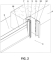
- Figure 2 shows a detailed perspective view of the installation assembly, linked to the inner surface (4) of a building and a canvas (10) of a quick-opening door (2) housed therein, closing the opening (5).
- the vertical frame (3) comprises a core (6) intended to be linked to the inner surface (4) of the building, a first wing (7) that extends orthogonally from one end of the core (6) and a first vertical guide (9) linked to the first wing (7) intended to face the opening (5) and partially house the edge of the canvas (10) of the quick-opening door (2).
- the vertical frame (3) comprises a second wing (11) that extends orthogonally from the other end of the core (6), intended to be located farther from the opening (5) than the first wing (7), longer than the first wing (7) and a second vertical guide (12) in the vicinity of the free end of the wing (11) which is intended to house the rolling elements (13) of the panels (14) of the sectional door (1).
- the assembly comprises a curtain of photocells (18) for each vertical frame (3), arranged on the second wing (11) facing the first wing (7) between the free end of the first wing (7) and the second vertical guide (12).
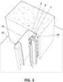
- FIG 3 shows a detailed perspective view of a second configuration of an installation assembly, linked to the inner surface (4) of a building.
- the curtain of photocells (18) is arranged on the first wing (7) between the first vertical guide (9) and the core (6).
- the assembly admits the installation of a curtain of photocells (18) or safety barrier that is used for the two doors (1, 2), generating economic savings in installation and material.
- Figure 4 shows a cross-sectional view of an installation assembly, installed on the inner surface (4) of a building.
- the first wing (7) is omega-shaped and has a first straight section (15) that extends orthogonally from the core (6), a central channel (16), and a second straight section (17), wherein the first vertical guide (9) is housed in the central channel (16).
- the second wing (11) is a straight section that extends from one end of the wing, intended to be farther from the opening (5) of the door than the first wing (7) and the second vertical guide (12) is linked to the end thereof.
- the second vertical guide (12) has a shape such that it enables and facilitates the guiding of the rolling elements (13).
- the assembly additionally comprises a polymeric guide (19) partially housed in the first vertical guide (9) which is equipped with a groove (20) that partially houses the canvas (10) of the high-speed door (2). It additionally comprises a sealing gasket (35) that surrounds the free end of the first wing (7).
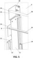
- Figure 5 shows a detailed perspective view of the assembly, which comprises a first support (22) intended to be linked to the inner surface (4) of the building and to the upper area of the vertical frame (3), which is equipped with a first hole (8), intended to house a shaft (25) of the sectional door.
- the assembly also comprises a second support (23) linked to the inner surface (4) in the upper area of the vertical frame (3), arranged below the first support (22), which is equipped with a second hole (24), intended to house a shaft (26) of the high-speed door (2).
- Both the supports (22, 23) and the core (6) of the respective vertical frames (3) can be linked to the wall by means of joining elements such as screws, etc., so they can have holes drilled to facilitate the wall installation of the assembly.
- the second vertical guide (12) is inclined with respect to the core (6), increasing the distance between the two in the upper area of the vertical frame (3), for which the second vertical guide (12) is joined by means of metal platens (21) to the second wing (11).
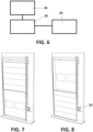
- Figure 6 shows a schematic view of the method for selectively activating the door lock comprising the steps of receiving the information on the opening or closing status of a sectional door (1) or a high-speed door (2) by means of a sensor (34), which can be housed in a vertical frame (3), verifying the information received by means of a receiver (28) and sending the received information to a control unit (29) and locking the closing of the sectional door (1) or the quick-opening door (2) by means of the control unit (29) based on the received information, preventing one of the doors (1, 2) from closing if the other door (1, 2) is closed.
- a sensor 34
- Figure 7 shows a second perspective view in a situation wherein the sectional door (1) is open and the quick-opening door (2) is closed.
- Figure 8 shows a third perspective view in a situation wherein the sectional door (1) is closed and the quick-opening door (2) is open.
Landscapes
- Engineering & Computer Science (AREA)
- Civil Engineering (AREA)
- Structural Engineering (AREA)
- Mechanical Engineering (AREA)
- Wing Frames And Configurations (AREA)
Priority Applications (1)
| Application Number | Priority Date | Filing Date | Title |
|---|---|---|---|
| EP22382113.3A EP4227481A1 (fr) | 2022-02-11 | 2022-02-11 | Installation de la porte pour une porte double et méthode de verrouillage associée |
Applications Claiming Priority (1)
| Application Number | Priority Date | Filing Date | Title |
|---|---|---|---|
| EP22382113.3A EP4227481A1 (fr) | 2022-02-11 | 2022-02-11 | Installation de la porte pour une porte double et méthode de verrouillage associée |
Publications (1)
| Publication Number | Publication Date |
|---|---|
| EP4227481A1 true EP4227481A1 (fr) | 2023-08-16 |
Family
ID=81327625
Family Applications (1)
| Application Number | Title | Priority Date | Filing Date |
|---|---|---|---|
| EP22382113.3A Withdrawn EP4227481A1 (fr) | 2022-02-11 | 2022-02-11 | Installation de la porte pour une porte double et méthode de verrouillage associée |
Country Status (1)
| Country | Link |
|---|---|
| EP (1) | EP4227481A1 (fr) |
Cited By (1)
| Publication number | Priority date | Publication date | Assignee | Title |
|---|---|---|---|---|
| CN118498861A (zh) * | 2024-07-19 | 2024-08-16 | 青岛悦益门业有限公司 | 重型提升门 |
Citations (2)
| Publication number | Priority date | Publication date | Assignee | Title |
|---|---|---|---|---|
| US6755231B1 (en) * | 1994-01-10 | 2004-06-29 | Chill Pill, Inc. | Shutter window/door and method |
| CA2463208C (fr) * | 2003-07-10 | 2008-01-22 | Tnr Industrial Doors Inc. | Porte rideau souple et guides connexes |
-
2022
- 2022-02-11 EP EP22382113.3A patent/EP4227481A1/fr not_active Withdrawn
Patent Citations (2)
| Publication number | Priority date | Publication date | Assignee | Title |
|---|---|---|---|---|
| US6755231B1 (en) * | 1994-01-10 | 2004-06-29 | Chill Pill, Inc. | Shutter window/door and method |
| CA2463208C (fr) * | 2003-07-10 | 2008-01-22 | Tnr Industrial Doors Inc. | Porte rideau souple et guides connexes |
Cited By (1)
| Publication number | Priority date | Publication date | Assignee | Title |
|---|---|---|---|---|
| CN118498861A (zh) * | 2024-07-19 | 2024-08-16 | 青岛悦益门业有限公司 | 重型提升门 |
Similar Documents
| Publication | Publication Date | Title |
|---|---|---|
| US6296039B1 (en) | Apparatus and method for windlocking a building opening | |
| US20130306252A1 (en) | Coiling door assembly having guide members with narrow wall gap opening and internal smoke or weather seal | |
| KR100443546B1 (ko) | 저마찰 에지를 갖는 말아올림형 도어 | |
| US6341639B1 (en) | Apparatus and method for windlocking a building opening | |
| US6431250B2 (en) | Apparatus and method for windlocking a building opening | |
| US9637972B2 (en) | Roll-up door and guide system therefor | |
| US9267326B2 (en) | Drive assisted roller assembly for rolling door | |
| US11203898B2 (en) | Security screen mounting system and method therefor | |
| US10876339B2 (en) | Overhead garage door system with sealing feature | |
| EP4227481A1 (fr) | Installation de la porte pour une porte double et méthode de verrouillage associée | |
| JP2001146884A (ja) | 閉鎖体のガイドレールの構造 | |
| US5983971A (en) | Reinforced burglar- and storm-resistant cover for windows and doors | |
| JP2005351082A (ja) | 閉鎖体のガイドレールの構造 | |
| EP3862505A1 (fr) | Agencement de verrouillage pour fixer une bande de bordure à un panneau | |
| EP4388167B1 (fr) | Ensemble profilé d'écran | |
| CN111051641A (zh) | 门系统 | |
| EP2031174B1 (fr) | Porte multiple | |
| KR100894724B1 (ko) | 오버헤드 도어용 패널의 보강장치 | |
| US4085788A (en) | Reinforcing means for roll-up shutter | |
| KR102372216B1 (ko) | 커버 결합형 대형 도어장치 | |
| EP4006295B1 (fr) | Agencement de protection pour une fenêtre de toit, et fenêtre de toit comprenant un tel agencement de protection | |
| AU2021102523A4 (en) | Vehicle window covering device | |
| KR100766359B1 (ko) | 건축구조물용 오버헤드 도어의 측면 보강구조 | |
| KR200440584Y1 (ko) | 승,하강식 도어용 도어패널 및 가이드레일의 보강구조 | |
| AU774863B2 (en) | Apparatus and method for windlocking a building opening |
Legal Events
| Date | Code | Title | Description |
|---|---|---|---|
| PUAI | Public reference made under article 153(3) epc to a published international application that has entered the european phase |
Free format text: ORIGINAL CODE: 0009012 |
|
| STAA | Information on the status of an ep patent application or granted ep patent |
Free format text: STATUS: THE APPLICATION HAS BEEN PUBLISHED |
|
| AK | Designated contracting states |
Kind code of ref document: A1 Designated state(s): AL AT BE BG CH CY CZ DE DK EE ES FI FR GB GR HR HU IE IS IT LI LT LU LV MC MK MT NL NO PL PT RO RS SE SI SK SM TR |
|
| STAA | Information on the status of an ep patent application or granted ep patent |
Free format text: STATUS: THE APPLICATION IS DEEMED TO BE WITHDRAWN |
|
| 18D | Application deemed to be withdrawn |
Effective date: 20240217 |