EP4227497B1 - Ensemble bride pour retenue d'élément de fixation et son procédé d'assemblage - Google Patents
Ensemble bride pour retenue d'élément de fixation et son procédé d'assemblage Download PDFInfo
- Publication number
- EP4227497B1 EP4227497B1 EP23155683.8A EP23155683A EP4227497B1 EP 4227497 B1 EP4227497 B1 EP 4227497B1 EP 23155683 A EP23155683 A EP 23155683A EP 4227497 B1 EP4227497 B1 EP 4227497B1
- Authority
- EP
- European Patent Office
- Prior art keywords
- flange
- primary
- bolt
- annular
- chamfer
- Prior art date
- Legal status (The legal status is an assumption and is not a legal conclusion. Google has not performed a legal analysis and makes no representation as to the accuracy of the status listed.)
- Active
Links
Images



Classifications
-
- F—MECHANICAL ENGINEERING; LIGHTING; HEATING; WEAPONS; BLASTING
- F01—MACHINES OR ENGINES IN GENERAL; ENGINE PLANTS IN GENERAL; STEAM ENGINES
- F01D—NON-POSITIVE DISPLACEMENT MACHINES OR ENGINES, e.g. STEAM TURBINES
- F01D25/00—Component parts, details, or accessories, not provided for in, or of interest apart from, other groups
- F01D25/24—Casings; Casing parts, e.g. diaphragms, casing fastenings
- F01D25/243—Flange connections; Bolting arrangements
-
- F—MECHANICAL ENGINEERING; LIGHTING; HEATING; WEAPONS; BLASTING
- F16—ENGINEERING ELEMENTS AND UNITS; GENERAL MEASURES FOR PRODUCING AND MAINTAINING EFFECTIVE FUNCTIONING OF MACHINES OR INSTALLATIONS; THERMAL INSULATION IN GENERAL
- F16B—DEVICES FOR FASTENING OR SECURING CONSTRUCTIONAL ELEMENTS OR MACHINE PARTS TOGETHER, e.g. NAILS, BOLTS, CIRCLIPS, CLAMPS, CLIPS OR WEDGES; JOINTS OR JOINTING
- F16B5/00—Joining sheets or plates, e.g. panels, to one another or to strips or bars parallel to them
- F16B5/02—Joining sheets or plates, e.g. panels, to one another or to strips or bars parallel to them by means of fastening members using screw-thread
-
- F—MECHANICAL ENGINEERING; LIGHTING; HEATING; WEAPONS; BLASTING
- F05—INDEXING SCHEMES RELATING TO ENGINES OR PUMPS IN VARIOUS SUBCLASSES OF CLASSES F01-F04
- F05D—INDEXING SCHEME FOR ASPECTS RELATING TO NON-POSITIVE-DISPLACEMENT MACHINES OR ENGINES, GAS-TURBINES OR JET-PROPULSION PLANTS
- F05D2230/00—Manufacture
- F05D2230/60—Assembly methods
- F05D2230/64—Assembly methods using positioning or alignment devices for aligning or centring, e.g. pins
-
- F—MECHANICAL ENGINEERING; LIGHTING; HEATING; WEAPONS; BLASTING
- F05—INDEXING SCHEMES RELATING TO ENGINES OR PUMPS IN VARIOUS SUBCLASSES OF CLASSES F01-F04
- F05D—INDEXING SCHEME FOR ASPECTS RELATING TO NON-POSITIVE-DISPLACEMENT MACHINES OR ENGINES, GAS-TURBINES OR JET-PROPULSION PLANTS
- F05D2240/00—Components
- F05D2240/10—Stators
- F05D2240/14—Casings or housings protecting or supporting assemblies within
-
- Y—GENERAL TAGGING OF NEW TECHNOLOGICAL DEVELOPMENTS; GENERAL TAGGING OF CROSS-SECTIONAL TECHNOLOGIES SPANNING OVER SEVERAL SECTIONS OF THE IPC; TECHNICAL SUBJECTS COVERED BY FORMER USPC CROSS-REFERENCE ART COLLECTIONS [XRACs] AND DIGESTS
- Y02—TECHNOLOGIES OR APPLICATIONS FOR MITIGATION OR ADAPTATION AGAINST CLIMATE CHANGE
- Y02E—REDUCTION OF GREENHOUSE GAS [GHG] EMISSIONS, RELATED TO ENERGY GENERATION, TRANSMISSION OR DISTRIBUTION
- Y02E10/00—Energy generation through renewable energy sources
- Y02E10/70—Wind energy
- Y02E10/72—Wind turbines with rotation axis in wind direction
Definitions
- This disclosure relates generally to flanges for rotational equipment and more particularly to fastener retention features of flange assemblies.
- bolts or other fasteners may be used to securely mount two or more components together.
- one side of a fastener may not be physically accessible at one or more points in the assembly process (e.g., a "blind assembly").
- a blind assembly There is a risk during the assembly process that one or more fasteners of a blind assembly may become partially or fully dislodged from their intended fastening position before they can be fully secured (e.g., using a nut).
- the one or more dislodged fasteners can potentially fall into a portion of the equipment which is no longer accessible.
- Some amount of disassembly of the equipment may then be needed to recover the one or more dislodged fasteners, thereby increasing the time and cost associated with equipment assembly. Accordingly, improved systems and methods for retaining fasteners during assembly are needed.
- EP 3 181 827 A1 discloses a prior art turbomachine component connection.
- EP 3 249 180 A1 discloses a prior art retention hardware.
- US 2013/202450 A1 discloses a prior art fastening system for fan and shaft interconnection.
- US 2013/309078 A1 discloses a prior art shield system for a gas turbine engine.
- a flange assembly as recited in claim 1.
- the flange assembly may further include a washer disposed about the bolt body and positioned between the primary flange and the second flange.
- the washer may be positioned axially within the recess of the secondary flange body.
- the washer may be positioned radially outside of the clip.
- the primary flange body may include an annular projection.
- the annular projection may extend axially from the second primary surface toward the first secondary surface.
- the annular projection may be positioned within the recess of the secondary flange body.
- the annular projection may be positioned radially outside of the clip.
- a first radial portion of the clip may be positioned radially inside the groove and a second radial portion of the clip may be positioned radially outside of the groove.
- the primary flange body may include an annular recess extending from the primary bolt aperture to the second primary surface.
- the annular recess may be positioned axially adjacent the clip.
- the annular recess may include an axially extending surface and a radially extending surface. The axially extending surface may be spaced from the annular surface of the bolt body by a distance and the distance may be less than a cross-sectional diameter of the clip.
- the primary flange body may include an annular chamfer extending from the primary bolt aperture to the second primary surface.
- the annular chamfer may be positioned axially adjacent the clip.
- the annular chamfer may include a chamfer surface extending between an inner radial chamfer end and an outer radial chamfer end.
- the chamfer surface may be flat in a direction extending between the inner radial chamfer end and the outer radial chamfer end.
- the clip may include a cross-sectional flat surface.
- the cross-sectional flat surface may be substantially parallel to the chamfer surface of the annular chamfer of the primary flange body.
- the chamfer surface may be disposed at an angle relative to a radial line.
- the angle may be between 20 and 60 degrees.
- the chamfer surface may be convex between the inner radial chamfer end and the outer radial chamfer end.
- the chamfer surface may be concave between the inner radial chamfer end and the outer radial chamfer end.
- the secondary flange body may include an annular recess formed between the secondary bolt aperture and the first secondary surface.
- the clip may be axially positioned within the annular recess, subsequent to the step of installing the secondary flange.
- the primary flange body may include an annular chamfer extending from the primary bolt aperture to the second primary surface.
- the annular chamfer may be positioned axially adjacent the clip, subsequent to the step of installing the clip onto the bolt.
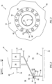
- the gas turbine engine 10 is schematically illustrated.
- the gas turbine engine 10 is disclosed herein as a two-spool turbofan engine that generally includes an inlet 12, a fan section 14, a compressor section 16, a combustor section 18, a turbine section 20, and an exhaust section 22.
- the fan section 14 drives air along a bypass flow path 24 while the compressor section 16 drives air along a core flow path 26 for compression and communication into the combustor section 18 and then expansion through the turbine section 20.
- turbofan gas turbine engine Although depicted as a turbofan gas turbine engine in the disclosed non-limiting embodiments, it should be understood that the concepts described herein are not limited to use with turbofans as the teachings may be applied to other types of gas turbine engines including those with single-spool or three-spool architectures. Moreover, aspects of the present disclosure are not limited in application to gas turbine engines and may be applicable to other aircraft propulsion systems as well.
- the gas turbine engine 10 of FIG. 1 includes a low-pressure spool 28 and a high-pressure spool 30 mounted for rotation about a longitudinal centerline 32 (e.g., a rotational axis) of the gas turbine engine 10 relative to an engine static structure 34 (e.g., an engine case).
- the low-pressure spool 28 includes a low-pressure shaft 36 that interconnects a fan 38, a low-pressure compressor 40, and a low-pressure turbine 42.
- the high-pressure spool 30 includes a high-pressure shaft 44 that interconnects a high-pressure compressor 46 and a high-pressure turbine 48. It is to be understood that "low pressure” and "high pressure” or variations thereof as used herein are relative terms indicating that the high pressure is greater than the low pressure.
- An annular combustor 50 is disposed between the high-pressure compressor 46 and the high-pressure turbine 48 along the longitudinal centerline 32.
- the low-pressure shaft 36 and the high-pressure shaft 44 are concentric and rotate about the longitudinal center
- Airflow along the core flow path 26 is compressed by the low-pressure compressor 40, then the high-pressure compressor 46, mixed and burned with fuel in the combustor 50, and then expanded over the high-pressure turbine 48 and the low-pressure turbine 42.
- the low-pressure turbine 42 and the high-pressure turbine 48 rotationally drive the low-pressure spool 28 and the high-pressure spool 30, respectively, in response to the expansion.
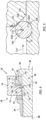
- FIGS. 2 and 3 illustrate a portion of the compressor section 16 including a mating interface between the low-pressure compressor 40 and the low-pressure shaft 36.
- the low-pressure compressor 40 of FIG. 2 includes a low-pressure compressor module 52 including a plurality of circumferentially-spaced compressor blades 54. The compressor blades 54 are positioned within the core flow path 26 and mounted for rotation about the longitudinal centerline 32.
- the low-pressure shaft 36 includes a low-pressure shaft flange 56 (hereinafter a "primary flange 56").
- the low-pressure compressor module 52 further includes a low-pressure compressor flange 58 (hereinafter a "secondary flange 58"), for example, at an upstream end of the low-pressure compressor module 52.
- the primary flange 56 and the secondary flange 58 are fixedly mounted to one another at a flange assembly 60.
- the primary flange 56 includes a primary flange body 62 extending outward from the longitudinal centerline 32 to a distal end 76.
- the primary flange body 62 includes a first primary surface 64 and a second primary surface 66 opposite the first primary surface 64.
- the primary flange body 62 defines a plurality of circumferentially-spaced primary bolt apertures 68 extending through the primary flange body 62 from the first primary surface 64 to the second primary surface 66.
- the secondary flange 58 includes a secondary flange body 70.
- the secondary flange body 70 includes a first secondary surface 72 and a second secondary surface 74 opposite the first secondary surface 72.
- the first secondary surface 72 of the secondary flange body 70 is positioned in contact with the second primary surface 66 of the primary flange body 62.
- the secondary flange body 70 may additionally be positioned in contact with other portions of the primary flange body 62 such as, for example, the distal end 76.
- the secondary flange body 70 defines a plurality of circumferentially-spaced secondary bolt apertures 78 extending through the primary flange body 70 from the first secondary surface 72 to the second secondary surface 74.
- Each secondary bolt aperture 78 of the plurality of secondary bolt apertures 78 is aligned with a respective one of the plurality of primary bolt apertures 68.
- the flange assembly 60 includes a plurality of bolts 80 or other fasteners configured to couple the primary flange 56 and the secondary flange 58.
- Each bolt 80 includes a bolt body 82 extending between a head end 84 and a distal end 86 along a bolt axis 88 (e.g., a center axis of the bolt 80).
- the bolt body 82 includes an annular surface 90 located between the head end 84 and the distal end 86.
- the annular surface 90 is disposed about the bolt axis 88.
- the bolt body 82 of each bolt 80 is positioned within respective ones of the plurality of primary bolt apertures 68 and the plurality of secondary bolt apertures 78.
- Each bolt 80 further includes a nut 94 detachably mounted (e.g., threadably mounted) to the bolt body 82 such that the primary flange 56 and the secondary flange 58 are positioned between the head end 84 and the nut 94 with the head end 84 adjacent the primary flange 56 and the nut 94 adjacent the secondary flange 58.
- the bolt 80 may include an annular washer 95 positioned between the nut 94 and the secondary flange 58.
- the plurality of bolts 80 may be installed in the respective plurality of primary bolt apertures 68 of the primary flange 56.
- the plurality of bolts 80 of FIG. 2 may be installed, for example, in a forward axial direction with respect to the longitudinal centerline 32.
- the low-pressure compressor module 52 may be installed.
- the secondary flange 58 of the low-pressure compressor module 52 may be installed into the flange assembly 60 such that the plurality of bolts 80 are positioned in the respective plurality of secondary bolt apertures 78 of the secondary flange 58.
- the secondary flange 58 of FIG. 2 may be installed, for example, in an aft axial direction with respect to the longitudinal centerline 32. In other words, the secondary flange 58 may be installed in a direction in opposition to the direction of installation for the plurality of bolts 80.
- FIG. 2 The inaccessible portion of the compressor section 16 is identified in FIG. 2 as the inaccessible side 96 of the flange assembly 60.
- An opposing side of the flange assembly 60 remains physically accessible to the operators performing the assembly process and is identified in FIG. 2 as the accessible side 98 of the flange assembly 60.
- the head end 84 of each bolt body 82 is positioned within the inaccessible side 96 and physical access to the head end 84 of each bolt body 82 may not be possible without removal of the secondary flange 58.
- TMS torque measuring system
- any bolts 80 which become dislodged from the flange assembly 60 must be recovered, which may require removal of the low-pressure compressor module 52 and/or other components of the gas turbine engine 10. While aspects of the present disclosure are described herein with respect to an exemplary mating interface between the low-pressure compressor 40 and the low-pressure shaft 36, aspects of the present disclosure flange assembly 60 are applicable for any blind assemblies in which a fastener, such as a bolt, may have one side (e.g., a head of the bolt) that is inaccessible during a portion of an assembly sequence.
- compressors such as the low-pressure compressor 40, turbofan gas turbine engines, such as the gas turbine engine 10, or even gas turbines engines in general, and may be relevant in the assembly of other forms of machinery and industrial equipment as well.
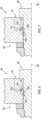
- FIGS. 4-12 side cross-sectional views of embodiments of the flange assembly 60 are illustrated including a bolt 80 of the plurality of bolts 80 installed in respective ones of the plurality of primary bolt apertures 68 and the plurality of secondary bolt apertures 78.
- the bolt 80 includes an annular groove 100 formed in the annular surface 90 of the bolt body 82 and disposed about the bolt axis 88.
- the flange assembly 60 further includes a clip 102 attached to the bolt body 82 within the annular groove 100. In other words, the clip 102 is seated within the annular groove 100. The clip 102 is positioned between the primary flange 56 and the secondary flange 58.
- the clip 102 may be configured as a C-clip (sometimes known as a "circlip") which may be formed by a semi-rigid ring with open ends which can be snapped into place about the bolt axis 88 within the annular groove 100. As shown in FIG. 5 , the clip 102 includes a first radial portion 102A positioned radially within the annular groove 100 and a second radial portion 102B positioned radially outside the annular groove 100, with respect to the bolt axis 88.
- a C-clip sometimes known as a "circlip”
- any dislodging force e.g., an axial force
- any dislodging force applied to the bolt 80 may cause the clip 102 to contact the second primary surface 66 of the primary flange body 62 of the primary flange 56, thereby potentially preventing the bolt 80 from being dislodged from the flange assembly 60.
- more significant dislodging forces may be capable of unseating the clip 102 from the annular groove 100, thereby allowing the bolt 80 to become dislodged from the flange assembly 60.
- the secondary flange body 70 may include an annular recess 104 formed between the secondary bolt aperture 78 and the first secondary surface 72.
- the clip 102 may be axially retained within the annular recess 104, with respect to the bolt axis 88. With the clip 102 positioned within the annular groove 100 of the bolt body 82, the secondary flange body 70 may be radially spaced from the clip 102, with respect to the bolt axis 88, at the location of the annular recess 104.
- the primary flange body 62 may include an annular chamfer 106 extending from the primary bolt aperture 68 to the second primary surface 66.
- the annular chamfer 106 is disposed about the bolt axis 88.
- the annular chamfer 106 is positioned axially adjacent the clip 102, with respect to the bolt axis 88.
- the annular chamfer 106 includes a chamfer surface 108 which extends between an inner radial chamfer end 110 and an outer radial chamfer end 112, with respect to the bolt axis 88.
- 3 and 4 is flat (e.g., linear) or substantially flat in a direction extending between the inner radial chamfer end 110 and the outer radial chamfer end 112.
- an axial dislodging force (schematically illustrated in FIG. 5 as force 114), with respect to the bolt axis 88, applied to the bolt 80 may cause the clip 102 to contact the chamfer surface 108 of the annular chamfer 106.
- the chamfer surface 108 may apply a radial retention force (schematically illustrated in FIG.
- FIG. 5 illustrates the clip 102 in contact with the chamfer surface 108 of the annular chamfer 106 of FIG. 4 .
- the annular groove 100 has a height h extending between a bottom of the annular groove 100 and the annular surface 90 of the bolt body 82.
- the clip 102 has a circular or substantially circular cross-sectional shape with a cross-sectional radius r.
- the height h of the annular groove 100 is illustrated in FIG. 5 as being less than the cross-sectional radius r.
- the present disclosure is not limited to this particular relationship between the height h and the cross-sectional radius r., and the height h may alternatively be greater than or equal to the cross-sectional radius r.
- a chamfer angle ⁇ is defined between the chamfer surface 108 (e.g., from the inner radial chamfer end 110 to the outer radial chamfer end 112) and an axial line 116 which is parallel to the bolt axis 88.
- the chamfer angle ⁇ of the chamfer surface 108 may be approximately forty-five degrees (45°).
- the chamfer angle ⁇ may preferably be between twenty degrees (20°) and sixty degrees (60°) or between thirty degrees (30°) and fifty degrees (50°).
- a chamfer angle may also be measured relative to a radial line, and may be between 20 and 60 degrees.
- the chamfer surface 108 may be curved in a direction extending between the inner radial chamfer end 110 and the outer radial chamfer end 112.
- the chamfer surface 108 of FIG. 6 is convex between the inner radial chamfer end 110 and the outer radial chamfer end 112.
- the chamfer surface 108 of FIG. 7 is concave between the inner radial chamfer end 110 and the outer radial chamfer end 112.
- the chamfer surface 108 may have a concave curvature which substantially matches the cross-sectional curvature of the clip 102.
- in clip 102 includes a cross-sectional flat surface 118.
- the cross-sectional flat surface 118 extends in a circumferential direction about the clip 102.
- the cross-sectional flat surface 118 is positioned on the clip 102 such that an axial withdrawal of the bolt 80 from the flange assembly 60 along the bolt axis 88 will cause the cross-sectional flat surface 118 to contact the chamfer surface 108 of the annular chamfer 106.
- the cross-sectional flat surface 118 of the clip 102 may be substantially parallel to the chamfer surface 108 of the annular chamfer 106 of the primary flange body 62.
- the term "substantially" with respect to a direction or angular relationship refers to the stated direction or angular relationship +/- five degrees (5°).
- the primary flange body 62 may include an annular recess 120 extending from the primary bolt aperture 68 to the second primary surface 66.
- the annular recess 120 is disposed about the bolt axis 88.
- the annular recess 120 is positioned axially adjacent the clip 102, with respect to the bolt axis 88.
- the annular recess 120 may have a substantially rectangular cross-sectional shape.
- the annular recess 120 may include an axially-extending surface 122 and a radially-extending surface 124 which intersects the axially-extending surface 122.
- the axially-extending surface 122 may be spaced (e.g., radially spaced) from the annular surface 90 of the bolt body 82 by a distance D1.
- the distance D1 may be less than a cross-sectional diameter D2 of the clip 102. Accordingly, if the clip 102 is axially positioned within the annular recess 120, the axially-extending surface 122 may prevent (e.g., physically obstruct) the clip 102 from being unseated from the annular groove 100 of the bolt body 82.
- the secondary flange body 70 includes an axially-extending surface 126 which defines a portion of the annular recess 104.
- the axially-extending surface 126 may be spaced (e.g., radially spaced) from the annular surface 90 of the bolt body 82 by a distance D3.
- the distance D3 may be less than the cross-sectional diameter D2 of the clip 102. Accordingly, with the clip 102 axially positioned within the annular recess 104, the axially-extending surface 126 may prevent (e.g., physically obstruct) the clip 102 from being unseated from the annular groove 100 of the bolt body 82.
- the flange assembly 60 may include a washer 128 disposed about the bolt body 82 and positioned between the primary flange 56 and the secondary flange 58.
- the washer 128 may be positioned axially within the recess 104 of the secondary flange body 70.
- the washer 128 may be positioned radially outside of the clip 102, with respect to the bolt axis 88. Accordingly, the washer 128 may prevent (e.g., physically obstruct) the clip 102 from being unseated from the annular groove 100 of the bolt body 82.
- the primary flange body 62 may include an annular projection 130.
- the annular projection 130 may extend axially from the second primary surface 66 toward the secondary flange body 70, with respect to the bolt axis 88.
- the annular projection 130 may be positioned within the annular recess 104 of the secondary flange body 70.
- the annular projection 130 may be positioned radially outside of the clip 102, with respect to the bolt axis 88. Accordingly, the annular projection 130 may prevent (e.g., physically obstruct) the clip 102 from being unseated from the annular groove 100 of the bolt body 82.
- the annular projection 130 may be formed as a unitary structure with the primary flange body 62.
- unitary structure means a single component, wherein the primary flange body 62 and the annular projection 130 are an inseparable body (e.g., formed of a single material, or a weldment of independent elements, etc.).
- a unitary structure of the primary flange body 62 and the annular projection 130 may decrease the potential for foreign object damage ("FOD”) to the gas turbine engine 10.
- FOD foreign object damage
Landscapes
- Engineering & Computer Science (AREA)
- General Engineering & Computer Science (AREA)
- Mechanical Engineering (AREA)
- Connection Of Plates (AREA)
Claims (15)
- Ensemble de brides (60) comprenant :une bride primaire (56) incluant un corps de bride primaire (62), le corps de bride primaire (62) incluant une première surface primaire (64) et une seconde surface primaire (66) opposée à la première surface primaire (64), le corps de bride primaire (62) définissant une ouverture de boulon primaire (68) se prolongeant de la première surface primaire (64) à la seconde surface primaire (66) ;une bride secondaire (58) positionnée adjacente à la bride primaire (56), la bride secondaire (58) incluant un corps de bride secondaire (70), le corps de bride secondaire (70) incluant une première surface secondaire (72) et une seconde surface secondaire (74) opposée à la première surface secondaire (72), le corps de bride secondaire (70) définissant une ouverture de boulon secondaire (78) se prolongeant de la première surface secondaire (72) à la seconde surface secondaire (74) ;un boulon (80) incluant un corps de boulon (82) se prolongeant entre une extrémité de tête (84) et une extrémité distale (86) le long d'un axe de boulon (88), le corps de boulon (82) incluant une surface annulaire (90) disposée autour de l'axe de boulon (88), le corps de boulon (82) étant positionné à l'intérieur de l'ouverture de boulon primaire (68) et de l'ouverture de boulon secondaire (78), le boulon (80) incluant également un écrou (94) monté de manière amovible sur le corps de boulon (82) de telle sorte que la bride primaire (56) et la bride secondaire (58) soient positionnées entre l'extrémité de tête (84) et l'écrou (94) avec l'extrémité de tête (84) adjacente à la bride primaire (56) ; caractérisé en ce que :le corps de boulon (82) inclut également une rainure annulaire (100) formée dans la surface annulaire (90) et disposée autour de l'axe de boulon (88), et présenteun clip (102) fixé au corps de boulon (82) à l'intérieur de la rainure annulaire (100), le clip (102) étant positionné entre la bride primaire (56) et la bride secondaire (58).
- Ensemble de brides (60) selon la revendication 1, dans lequel le corps de bride secondaire (70) inclut un évidement annulaire (104) formé entre l'ouverture de boulon secondaire (78) et la première surface secondaire (72) et dans lequel le clip (102) est positionné axialement à l'intérieur de l'évidement annulaire (104) .
- Ensemble de bride (60) selon la revendication 2, comprenant également une rondelle (128) disposée autour du corps de boulon (82) et positionnée entre la bride primaire (56) et la bride secondaire (58), la rondelle (128) étant positionnée axialement à l'intérieur de l'évidemment annulaire (104) du corps de bride secondaire (70), dans lequel la rondelle (128) est éventuellement positionnée radialement à l'extérieur du clip (102) .
- Ensemble de bride (60) selon la revendication 2, dans lequel le corps de bride primaire (62) inclut une saillie annulaire (130), la saillie annulaire (130) se prolongeant axialement depuis la seconde surface primaire (66) vers la première surface secondaire (72), la saillie annulaire (130) étant positionnée à l'intérieur de l'évidement annulaire (104) du corps de bride secondaire (70), dans lequel la saillie annulaire (130) est éventuellement positionnée radialement à l'extérieur du clip (102) .
- Ensemble de bride (60) selon l'une quelconque des revendications précédentes, dans lequel une première partie radiale (102A) du clip (102) est positionnée radialement à l'intérieur de la rainure annulaire (100) et une seconde partie radiale (102B) du clip (102) est positionnée radialement à l'extérieur de la rainure annulaire (100).
- Ensemble de bride (60) selon la revendication 1 ou 2, dans lequel le corps de bride primaire (62) inclut un évidement annulaire (120) se prolongeant de l'ouverture de boulon primaire (68) à la seconde surface primaire (66), l'évidement annulaire (120) étant positionné axialement adjacent au clip (102), l'évidement annulaire (120) incluant une surface se prolongeant axialement (122) et une surface se prolongeant radialement (124), la surface se prolongeant axialement (122) étant espacée de la surface annulaire (90) du corps de boulon (82) d'une distance (D1) et la distance (D1) est inférieure à un diamètre transversal (D2) du clip (102).
- Ensemble de bride (60) selon la revendication 1 ou 2, dans lequel le corps de bride primaire (62) inclut un chanfrein annulaire (106) se prolongeant de l'ouverture de boulon primaire (68) à la seconde surface primaire (66), le chanfrein annulaire (106) étant positionné axialement adjacent au clip (102).
- Ensemble de bride (60) selon la revendication 7, dans lequel le chanfrein annulaire (106) inclut une surface de chanfrein (108) se prolongeant entre une extrémité de chanfrein radial interne (110) et une extrémité de chanfrein radial externe (112) .
- Ensemble de bride (60) selon la revendication 8, dans lequel la surface de chanfrein (108) est plate dans une direction se prolongeant entre l'extrémité de chanfrein radial interne (110) et l'extrémité de chanfrein radial externe (112).
- Ensemble de bride (60) selon la revendication 9, dans lequel le clip (102) inclut une surface plate transversale (118), dans lequel la surface plate transversale (118) est éventuellement sensiblement parallèle à la surface de chanfrein (108) du chanfrein annulaire (106) du corps de bride primaire (62).
- Ensemble de bride (60) selon la revendication 8 ou 9, dans lequel la surface de chanfrein (108) est disposée à un angle par rapport à une ligne radiale, et l'angle est compris entre 20 et 60 degrés.
- Ensemble de bride (60) selon la revendication 8, dans lequel la surface de chanfrein (108) est convexe entre l'extrémité de chanfrein radial interne (110) et l'extrémité de chanfrein radial externe (112), ou dans lequel la surface de chanfrein (108) est concave entre l'extrémité de chanfrein radial interne (110) et l'extrémité de chanfrein radial externe (112).
- Procédé d'assemblage d'un ensemble de bride (60), le procédé comprenant :l'insertion d'un boulon (80), dans une première direction axiale, dans une ouverture de boulon primaire (68) d'une bride primaire (56), le boulon (80) incluant un corps de boulon (82) se prolongeant entre une extrémité de tête (84) et une extrémité distale (86) le long d'un axe de boulon (88), le corps de boulon (82) incluant une surface annulaire (90) disposée autour de l'axe de boulon (88), le corps de boulon (82) incluant également une rainure annulaire (100) formée dans la surface annulaire (90) et disposée autour de l'axe de boulon (88), la bride primaire (56) incluant un corps de bride primaire (62), le corps de bride primaire (62) incluant une première surface primaire (64) et une seconde surface primaire (66) opposée à la première surface primaire (64) ;l'installation d'un clip (102) sur le boulon (80) de sorte que le clip (102) soit fixé au corps du boulon (82) à l'intérieur de la rainure annulaire (100) ;l'installation d'une bride secondaire (58) sur le boulon (80) dans une seconde direction axiale, opposée à la première direction axiale, de sorte que le corps de boulon (82) soit positionné à l'intérieur d'une ouverture de boulon secondaire (78) de la bride secondaire (58) avec la bride secondaire (58) positionnée adjacente à la bride primaire (56) et avec le clip (102) positionné entre la bride primaire (56) et la bride secondaire (58), la bride secondaire (58) incluant un corps de bride secondaire (70), le corps de bride secondaire (70) incluant une première surface secondaire (72) et une seconde surface secondaire (74) opposée à la première surface secondaire (72) ; etle montage d'un écrou (94) sur le corps de boulon (82) avec la bride primaire (56) et la bride secondaire (58) positionnées entre l'extrémité de tête (84) et l'écrou (94).
- Procédé selon la revendication 13, dans lequel le corps de bride secondaire (70) inclut un évidement annulaire (104) formé entre l'ouverture de boulon secondaire (78) et la première surface secondaire (72) et dans lequel le clip (102) est positionné axialement à l'intérieur de l'évidement annulaire (104), après l'étape d'installation de la bride secondaire (58).
- Procédé selon la revendication 13 ou 14, dans lequel le corps de bride primaire (62) inclut un chanfrein annulaire (106) se prolongeant de l'ouverture de boulon primaire (68) à la seconde surface primaire (66), le chanfrein annulaire (106) étant positionné axialement adjacent au clip (102), après l'étape d'installation du clip (102) sur le boulon (80).
Applications Claiming Priority (1)
| Application Number | Priority Date | Filing Date | Title |
|---|---|---|---|
| US17/670,143 US12066051B2 (en) | 2022-02-11 | 2022-02-11 | Flange assembly for fastener retention and method for assembling same |
Publications (2)
| Publication Number | Publication Date |
|---|---|
| EP4227497A1 EP4227497A1 (fr) | 2023-08-16 |
| EP4227497B1 true EP4227497B1 (fr) | 2024-12-25 |
Family
ID=85202214
Family Applications (1)
| Application Number | Title | Priority Date | Filing Date |
|---|---|---|---|
| EP23155683.8A Active EP4227497B1 (fr) | 2022-02-11 | 2023-02-08 | Ensemble bride pour retenue d'élément de fixation et son procédé d'assemblage |
Country Status (3)
| Country | Link |
|---|---|
| US (1) | US12066051B2 (fr) |
| EP (1) | EP4227497B1 (fr) |
| CA (1) | CA3189524A1 (fr) |
Family Cites Families (7)
| Publication number | Priority date | Publication date | Assignee | Title |
|---|---|---|---|---|
| US8932022B2 (en) | 2012-02-03 | 2015-01-13 | Pratt & Whitney Canada Corp. | Fastening system for fan and shaft interconnection |
| US9133723B2 (en) | 2012-05-21 | 2015-09-15 | United Technologies Corporation | Shield system for gas turbine engine |
| DE102013017713B4 (de) | 2013-10-24 | 2022-10-27 | Man Energy Solutions Se | Turbomaschine |
| ES2861200T3 (es) * | 2015-12-15 | 2021-10-06 | MTU Aero Engines AG | Conexión de componentes de turbomaquinaria |
| DE102016002269B4 (de) | 2016-02-26 | 2021-08-26 | Feinguss Blank Gmbh | Ventilelement |
| US10563542B2 (en) | 2016-05-23 | 2020-02-18 | United Technologies Corporation | Retention hardware |
| CN209511358U (zh) | 2018-12-05 | 2019-10-18 | 无锡威孚力达催化净化器有限责任公司 | 一种压入式防脱落法兰螺栓组件 |
-
2022
- 2022-02-11 US US17/670,143 patent/US12066051B2/en active Active
-
2023
- 2023-02-08 EP EP23155683.8A patent/EP4227497B1/fr active Active
- 2023-02-09 CA CA3189524A patent/CA3189524A1/fr active Pending
Also Published As
| Publication number | Publication date |
|---|---|
| EP4227497A1 (fr) | 2023-08-16 |
| US12066051B2 (en) | 2024-08-20 |
| US20230258210A1 (en) | 2023-08-17 |
| CA3189524A1 (fr) | 2023-08-11 |
Similar Documents
| Publication | Publication Date | Title |
|---|---|---|
| US9371863B2 (en) | Turbine engine coupling stack | |
| US8572987B2 (en) | Fuel injector mounting system | |
| US8511983B2 (en) | LPC exit guide vane and assembly | |
| EP2855895B1 (fr) | Ensemble de verrouillage de plaque de recouvrement de rotor de turbine | |
| KR101779146B1 (ko) | 교체가능 마손 스트립을 갖는 인터 스테이지 실 하우징 | |
| RU2436965C2 (ru) | Устройство для крепления направляющего соплового аппарата турбины, турбина и двигатель самолета с таким оборудованием | |
| EP3508687B1 (fr) | Ensemble d'alignement gérant les cannelures tolérant les dommages | |
| US20150338005A1 (en) | Cooling systems for gas turbine engine components | |
| US10865652B2 (en) | Method and device for piston seal anti-rotation | |
| US10821583B2 (en) | Spring loaded pilot punch assembly | |
| US8959743B2 (en) | Retaining ring removal tool | |
| EP4227497B1 (fr) | Ensemble bride pour retenue d'élément de fixation et son procédé d'assemblage | |
| EP4174290B1 (fr) | Plaque de support pour bride de carter de moteur de turbine à gas | |
| US6773228B2 (en) | Methods and apparatus for turbine nozzle locks | |
| US9045984B2 (en) | Stator vane mistake proofing | |
| EP3865659B1 (fr) | Adaptateur de sonde et son procédé d'utilisation | |
| US9285205B2 (en) | Turbomachine probe retention feature | |
| EP3252322B1 (fr) | Boulon de centrage | |
| EP4428422A2 (fr) | Dispositif mécanique de dissuasion pour joint d'assemblage de fluide | |
| US12460727B2 (en) | Self-centering seal and method of using same | |
| US20160230599A1 (en) | Flangeless conical sleeve and method of repair |
Legal Events
| Date | Code | Title | Description |
|---|---|---|---|
| PUAI | Public reference made under article 153(3) epc to a published international application that has entered the european phase |
Free format text: ORIGINAL CODE: 0009012 |
|
| STAA | Information on the status of an ep patent application or granted ep patent |
Free format text: STATUS: THE APPLICATION HAS BEEN PUBLISHED |
|
| AK | Designated contracting states |
Kind code of ref document: A1 Designated state(s): AL AT BE BG CH CY CZ DE DK EE ES FI FR GB GR HR HU IE IS IT LI LT LU LV MC ME MK MT NL NO PL PT RO RS SE SI SK SM TR |
|
| STAA | Information on the status of an ep patent application or granted ep patent |
Free format text: STATUS: REQUEST FOR EXAMINATION WAS MADE |
|
| 17P | Request for examination filed |
Effective date: 20240215 |
|
| RBV | Designated contracting states (corrected) |
Designated state(s): AL AT BE BG CH CY CZ DE DK EE ES FI FR GB GR HR HU IE IS IT LI LT LU LV MC ME MK MT NL NO PL PT RO RS SE SI SK SM TR |
|
| RIC1 | Information provided on ipc code assigned before grant |
Ipc: F01D 25/24 20060101AFI20240613BHEP |
|
| GRAP | Despatch of communication of intention to grant a patent |
Free format text: ORIGINAL CODE: EPIDOSNIGR1 |
|
| STAA | Information on the status of an ep patent application or granted ep patent |
Free format text: STATUS: GRANT OF PATENT IS INTENDED |
|
| INTG | Intention to grant announced |
Effective date: 20240723 |
|
| GRAS | Grant fee paid |
Free format text: ORIGINAL CODE: EPIDOSNIGR3 |
|
| GRAA | (expected) grant |
Free format text: ORIGINAL CODE: 0009210 |
|
| STAA | Information on the status of an ep patent application or granted ep patent |
Free format text: STATUS: THE PATENT HAS BEEN GRANTED |
|
| AK | Designated contracting states |
Kind code of ref document: B1 Designated state(s): AL AT BE BG CH CY CZ DE DK EE ES FI FR GB GR HR HU IE IS IT LI LT LU LV MC ME MK MT NL NO PL PT RO RS SE SI SK SM TR |
|
| REG | Reference to a national code |
Ref country code: GB Ref legal event code: FG4D |
|
| REG | Reference to a national code |
Ref country code: CH Ref legal event code: EP |
|
| REG | Reference to a national code |
Ref country code: DE Ref legal event code: R096 Ref document number: 602023001434 Country of ref document: DE |
|
| REG | Reference to a national code |
Ref country code: IE Ref legal event code: FG4D |
|
| REG | Reference to a national code |
Ref country code: LT Ref legal event code: MG9D |
|
| PG25 | Lapsed in a contracting state [announced via postgrant information from national office to epo] |
Ref country code: HR Free format text: LAPSE BECAUSE OF FAILURE TO SUBMIT A TRANSLATION OF THE DESCRIPTION OR TO PAY THE FEE WITHIN THE PRESCRIBED TIME-LIMIT Effective date: 20241225 |
|
| PG25 | Lapsed in a contracting state [announced via postgrant information from national office to epo] |
Ref country code: FI Free format text: LAPSE BECAUSE OF FAILURE TO SUBMIT A TRANSLATION OF THE DESCRIPTION OR TO PAY THE FEE WITHIN THE PRESCRIBED TIME-LIMIT Effective date: 20241225 |
|
| PG25 | Lapsed in a contracting state [announced via postgrant information from national office to epo] |
Ref country code: BG Free format text: LAPSE BECAUSE OF FAILURE TO SUBMIT A TRANSLATION OF THE DESCRIPTION OR TO PAY THE FEE WITHIN THE PRESCRIBED TIME-LIMIT Effective date: 20241225 |
|
| PG25 | Lapsed in a contracting state [announced via postgrant information from national office to epo] |
Ref country code: NO Free format text: LAPSE BECAUSE OF FAILURE TO SUBMIT A TRANSLATION OF THE DESCRIPTION OR TO PAY THE FEE WITHIN THE PRESCRIBED TIME-LIMIT Effective date: 20250325 |
|
| PG25 | Lapsed in a contracting state [announced via postgrant information from national office to epo] |
Ref country code: LV Free format text: LAPSE BECAUSE OF FAILURE TO SUBMIT A TRANSLATION OF THE DESCRIPTION OR TO PAY THE FEE WITHIN THE PRESCRIBED TIME-LIMIT Effective date: 20241225 Ref country code: GR Free format text: LAPSE BECAUSE OF FAILURE TO SUBMIT A TRANSLATION OF THE DESCRIPTION OR TO PAY THE FEE WITHIN THE PRESCRIBED TIME-LIMIT Effective date: 20250326 |
|
| PGFP | Annual fee paid to national office [announced via postgrant information from national office to epo] |
Ref country code: AT Payment date: 20250417 Year of fee payment: 3 |
|
| PG25 | Lapsed in a contracting state [announced via postgrant information from national office to epo] |
Ref country code: RS Free format text: LAPSE BECAUSE OF FAILURE TO SUBMIT A TRANSLATION OF THE DESCRIPTION OR TO PAY THE FEE WITHIN THE PRESCRIBED TIME-LIMIT Effective date: 20250325 |
|
| REG | Reference to a national code |
Ref country code: NL Ref legal event code: MP Effective date: 20241225 |
|
| PG25 | Lapsed in a contracting state [announced via postgrant information from national office to epo] |
Ref country code: NL Free format text: LAPSE BECAUSE OF FAILURE TO SUBMIT A TRANSLATION OF THE DESCRIPTION OR TO PAY THE FEE WITHIN THE PRESCRIBED TIME-LIMIT Effective date: 20241225 |
|
| REG | Reference to a national code |
Ref country code: AT Ref legal event code: MK05 Ref document number: 1754324 Country of ref document: AT Kind code of ref document: T Effective date: 20241225 |
|
| PG25 | Lapsed in a contracting state [announced via postgrant information from national office to epo] |
Ref country code: SM Free format text: LAPSE BECAUSE OF FAILURE TO SUBMIT A TRANSLATION OF THE DESCRIPTION OR TO PAY THE FEE WITHIN THE PRESCRIBED TIME-LIMIT Effective date: 20241225 |
|
| PG25 | Lapsed in a contracting state [announced via postgrant information from national office to epo] |
Ref country code: PL Free format text: LAPSE BECAUSE OF FAILURE TO SUBMIT A TRANSLATION OF THE DESCRIPTION OR TO PAY THE FEE WITHIN THE PRESCRIBED TIME-LIMIT Effective date: 20241225 |
|
| PG25 | Lapsed in a contracting state [announced via postgrant information from national office to epo] |
Ref country code: ES Free format text: LAPSE BECAUSE OF FAILURE TO SUBMIT A TRANSLATION OF THE DESCRIPTION OR TO PAY THE FEE WITHIN THE PRESCRIBED TIME-LIMIT Effective date: 20241225 |
|
| PG25 | Lapsed in a contracting state [announced via postgrant information from national office to epo] |
Ref country code: IS Free format text: LAPSE BECAUSE OF FAILURE TO SUBMIT A TRANSLATION OF THE DESCRIPTION OR TO PAY THE FEE WITHIN THE PRESCRIBED TIME-LIMIT Effective date: 20250425 |
|
| PG25 | Lapsed in a contracting state [announced via postgrant information from national office to epo] |
Ref country code: PT Free format text: LAPSE BECAUSE OF FAILURE TO SUBMIT A TRANSLATION OF THE DESCRIPTION OR TO PAY THE FEE WITHIN THE PRESCRIBED TIME-LIMIT Effective date: 20250428 |
|
| PG25 | Lapsed in a contracting state [announced via postgrant information from national office to epo] |
Ref country code: EE Free format text: LAPSE BECAUSE OF FAILURE TO SUBMIT A TRANSLATION OF THE DESCRIPTION OR TO PAY THE FEE WITHIN THE PRESCRIBED TIME-LIMIT Effective date: 20241225 |
|
| PG25 | Lapsed in a contracting state [announced via postgrant information from national office to epo] |
Ref country code: AT Free format text: LAPSE BECAUSE OF FAILURE TO SUBMIT A TRANSLATION OF THE DESCRIPTION OR TO PAY THE FEE WITHIN THE PRESCRIBED TIME-LIMIT Effective date: 20241225 Ref country code: RO Free format text: LAPSE BECAUSE OF FAILURE TO SUBMIT A TRANSLATION OF THE DESCRIPTION OR TO PAY THE FEE WITHIN THE PRESCRIBED TIME-LIMIT Effective date: 20241225 |
|
| PG25 | Lapsed in a contracting state [announced via postgrant information from national office to epo] |
Ref country code: SK Free format text: LAPSE BECAUSE OF FAILURE TO SUBMIT A TRANSLATION OF THE DESCRIPTION OR TO PAY THE FEE WITHIN THE PRESCRIBED TIME-LIMIT Effective date: 20241225 |
|
| PG25 | Lapsed in a contracting state [announced via postgrant information from national office to epo] |
Ref country code: CZ Free format text: LAPSE BECAUSE OF FAILURE TO SUBMIT A TRANSLATION OF THE DESCRIPTION OR TO PAY THE FEE WITHIN THE PRESCRIBED TIME-LIMIT Effective date: 20241225 |
|
| PG25 | Lapsed in a contracting state [announced via postgrant information from national office to epo] |
Ref country code: IT Free format text: LAPSE BECAUSE OF FAILURE TO SUBMIT A TRANSLATION OF THE DESCRIPTION OR TO PAY THE FEE WITHIN THE PRESCRIBED TIME-LIMIT Effective date: 20241225 |
|
| PG25 | Lapsed in a contracting state [announced via postgrant information from national office to epo] |
Ref country code: SE Free format text: LAPSE BECAUSE OF FAILURE TO SUBMIT A TRANSLATION OF THE DESCRIPTION OR TO PAY THE FEE WITHIN THE PRESCRIBED TIME-LIMIT Effective date: 20241225 |
|
| PG25 | Lapsed in a contracting state [announced via postgrant information from national office to epo] |
Ref country code: MC Free format text: LAPSE BECAUSE OF FAILURE TO SUBMIT A TRANSLATION OF THE DESCRIPTION OR TO PAY THE FEE WITHIN THE PRESCRIBED TIME-LIMIT Effective date: 20241225 |
|
| REG | Reference to a national code |
Ref country code: DE Ref legal event code: R097 Ref document number: 602023001434 Country of ref document: DE |
|
| PG25 | Lapsed in a contracting state [announced via postgrant information from national office to epo] |
Ref country code: DK Free format text: LAPSE BECAUSE OF FAILURE TO SUBMIT A TRANSLATION OF THE DESCRIPTION OR TO PAY THE FEE WITHIN THE PRESCRIBED TIME-LIMIT Effective date: 20241225 |
|
| PG25 | Lapsed in a contracting state [announced via postgrant information from national office to epo] |
Ref country code: LU Free format text: LAPSE BECAUSE OF NON-PAYMENT OF DUE FEES Effective date: 20250208 |
|
| PLBE | No opposition filed within time limit |
Free format text: ORIGINAL CODE: 0009261 |
|
| STAA | Information on the status of an ep patent application or granted ep patent |
Free format text: STATUS: NO OPPOSITION FILED WITHIN TIME LIMIT |
|
| 26N | No opposition filed |
Effective date: 20250926 |
|
| REG | Reference to a national code |
Ref country code: BE Ref legal event code: MM Effective date: 20250228 |
|
| PG25 | Lapsed in a contracting state [announced via postgrant information from national office to epo] |
Ref country code: BE Free format text: LAPSE BECAUSE OF NON-PAYMENT OF DUE FEES Effective date: 20250228 |
|
| PG25 | Lapsed in a contracting state [announced via postgrant information from national office to epo] |
Ref country code: IE Free format text: LAPSE BECAUSE OF NON-PAYMENT OF DUE FEES Effective date: 20250208 |
|
| PGFP | Annual fee paid to national office [announced via postgrant information from national office to epo] |
Ref country code: DE Payment date: 20260121 Year of fee payment: 4 |
|
| PGFP | Annual fee paid to national office [announced via postgrant information from national office to epo] |
Ref country code: FR Payment date: 20260121 Year of fee payment: 4 |