EP4227600A1 - Solarmodul-montagesystem - Google Patents
Solarmodul-montagesystem Download PDFInfo
- Publication number
- EP4227600A1 EP4227600A1 EP23173962.4A EP23173962A EP4227600A1 EP 4227600 A1 EP4227600 A1 EP 4227600A1 EP 23173962 A EP23173962 A EP 23173962A EP 4227600 A1 EP4227600 A1 EP 4227600A1
- Authority
- EP
- European Patent Office
- Prior art keywords
- mounting bracket
- torque tube
- mounting
- solar module
- retainer assembly
- Prior art date
- Legal status (The legal status is an assumption and is not a legal conclusion. Google has not performed a legal analysis and makes no representation as to the accuracy of the status listed.)
- Pending
Links
Images


Classifications
-
- H—ELECTRICITY
- H02—GENERATION; CONVERSION OR DISTRIBUTION OF ELECTRIC POWER
- H02S—GENERATION OF ELECTRIC POWER BY CONVERSION OF INFRARED RADIATION, VISIBLE LIGHT OR ULTRAVIOLET LIGHT, e.g. USING PHOTOVOLTAIC [PV] MODULES
- H02S20/00—Supporting structures for PV modules
- H02S20/30—Supporting structures being movable or adjustable, e.g. for angle adjustment
- H02S20/32—Supporting structures being movable or adjustable, e.g. for angle adjustment specially adapted for solar tracking
-
- H—ELECTRICITY
- H02—GENERATION; CONVERSION OR DISTRIBUTION OF ELECTRIC POWER
- H02S—GENERATION OF ELECTRIC POWER BY CONVERSION OF INFRARED RADIATION, VISIBLE LIGHT OR ULTRAVIOLET LIGHT, e.g. USING PHOTOVOLTAIC [PV] MODULES
- H02S20/00—Supporting structures for PV modules
- H02S20/10—Supporting structures directly fixed to the ground
-
- F—MECHANICAL ENGINEERING; LIGHTING; HEATING; WEAPONS; BLASTING
- F24—HEATING; RANGES; VENTILATING
- F24S—SOLAR HEAT COLLECTORS; SOLAR HEAT SYSTEMS
- F24S30/00—Arrangements for moving or orienting solar heat collector modules
- F24S30/40—Arrangements for moving or orienting solar heat collector modules for rotary movement
- F24S30/42—Arrangements for moving or orienting solar heat collector modules for rotary movement with only one rotation axis
- F24S30/425—Horizontal axis
-
- F—MECHANICAL ENGINEERING; LIGHTING; HEATING; WEAPONS; BLASTING
- F24—HEATING; RANGES; VENTILATING
- F24S—SOLAR HEAT COLLECTORS; SOLAR HEAT SYSTEMS
- F24S25/00—Arrangement of stationary mountings or supports for solar heat collector modules
- F24S25/20—Peripheral frames for modules
-
- F—MECHANICAL ENGINEERING; LIGHTING; HEATING; WEAPONS; BLASTING
- F24—HEATING; RANGES; VENTILATING
- F24S—SOLAR HEAT COLLECTORS; SOLAR HEAT SYSTEMS
- F24S25/00—Arrangement of stationary mountings or supports for solar heat collector modules
- F24S25/60—Fixation means, e.g. fasteners, specially adapted for supporting solar heat collector modules
- F24S25/63—Fixation means, e.g. fasteners, specially adapted for supporting solar heat collector modules for fixing modules or their peripheral frames to supporting elements
- F24S25/632—Side connectors; Base connectors
-
- F—MECHANICAL ENGINEERING; LIGHTING; HEATING; WEAPONS; BLASTING
- F24—HEATING; RANGES; VENTILATING
- F24S—SOLAR HEAT COLLECTORS; SOLAR HEAT SYSTEMS
- F24S30/00—Arrangements for moving or orienting solar heat collector modules
- F24S30/40—Arrangements for moving or orienting solar heat collector modules for rotary movement
-
- H—ELECTRICITY
- H02—GENERATION; CONVERSION OR DISTRIBUTION OF ELECTRIC POWER
- H02S—GENERATION OF ELECTRIC POWER BY CONVERSION OF INFRARED RADIATION, VISIBLE LIGHT OR ULTRAVIOLET LIGHT, e.g. USING PHOTOVOLTAIC [PV] MODULES
- H02S30/00—Structural details of PV modules other than those related to light conversion
- H02S30/10—Frame structures
-
- F—MECHANICAL ENGINEERING; LIGHTING; HEATING; WEAPONS; BLASTING
- F24—HEATING; RANGES; VENTILATING
- F24S—SOLAR HEAT COLLECTORS; SOLAR HEAT SYSTEMS
- F24S25/00—Arrangement of stationary mountings or supports for solar heat collector modules
- F24S25/60—Fixation means, e.g. fasteners, specially adapted for supporting solar heat collector modules
- F24S2025/6002—Fixation means, e.g. fasteners, specially adapted for supporting solar heat collector modules by using hooks
-
- F—MECHANICAL ENGINEERING; LIGHTING; HEATING; WEAPONS; BLASTING
- F24—HEATING; RANGES; VENTILATING
- F24S—SOLAR HEAT COLLECTORS; SOLAR HEAT SYSTEMS
- F24S25/00—Arrangement of stationary mountings or supports for solar heat collector modules
- F24S25/60—Fixation means, e.g. fasteners, specially adapted for supporting solar heat collector modules
- F24S2025/6005—Fixation means, e.g. fasteners, specially adapted for supporting solar heat collector modules by screwed connection
-
- F—MECHANICAL ENGINEERING; LIGHTING; HEATING; WEAPONS; BLASTING
- F24—HEATING; RANGES; VENTILATING
- F24S—SOLAR HEAT COLLECTORS; SOLAR HEAT SYSTEMS
- F24S25/00—Arrangement of stationary mountings or supports for solar heat collector modules
- F24S25/60—Fixation means, e.g. fasteners, specially adapted for supporting solar heat collector modules
- F24S2025/6006—Fixation means, e.g. fasteners, specially adapted for supporting solar heat collector modules by using threaded elements, e.g. stud bolts
-
- F—MECHANICAL ENGINEERING; LIGHTING; HEATING; WEAPONS; BLASTING
- F24—HEATING; RANGES; VENTILATING
- F24S—SOLAR HEAT COLLECTORS; SOLAR HEAT SYSTEMS
- F24S25/00—Arrangement of stationary mountings or supports for solar heat collector modules
- F24S25/60—Fixation means, e.g. fasteners, specially adapted for supporting solar heat collector modules
- F24S2025/6007—Fixation means, e.g. fasteners, specially adapted for supporting solar heat collector modules by using form-fitting connection means, e.g. tongue and groove
-
- F—MECHANICAL ENGINEERING; LIGHTING; HEATING; WEAPONS; BLASTING
- F24—HEATING; RANGES; VENTILATING
- F24S—SOLAR HEAT COLLECTORS; SOLAR HEAT SYSTEMS
- F24S25/00—Arrangement of stationary mountings or supports for solar heat collector modules
- F24S25/60—Fixation means, e.g. fasteners, specially adapted for supporting solar heat collector modules
- F24S2025/6008—Fixation means, e.g. fasteners, specially adapted for supporting solar heat collector modules by using toothed elements
-
- F—MECHANICAL ENGINEERING; LIGHTING; HEATING; WEAPONS; BLASTING
- F24—HEATING; RANGES; VENTILATING
- F24S—SOLAR HEAT COLLECTORS; SOLAR HEAT SYSTEMS
- F24S30/00—Arrangements for moving or orienting solar heat collector modules
- F24S2030/10—Special components
-
- F—MECHANICAL ENGINEERING; LIGHTING; HEATING; WEAPONS; BLASTING
- F24—HEATING; RANGES; VENTILATING
- F24S—SOLAR HEAT COLLECTORS; SOLAR HEAT SYSTEMS
- F24S30/00—Arrangements for moving or orienting solar heat collector modules
- F24S2030/10—Special components
- F24S2030/13—Transmissions
-
- F—MECHANICAL ENGINEERING; LIGHTING; HEATING; WEAPONS; BLASTING
- F24—HEATING; RANGES; VENTILATING
- F24S—SOLAR HEAT COLLECTORS; SOLAR HEAT SYSTEMS
- F24S30/00—Arrangements for moving or orienting solar heat collector modules
- F24S2030/10—Special components
- F24S2030/15—Bearings
-
- F—MECHANICAL ENGINEERING; LIGHTING; HEATING; WEAPONS; BLASTING
- F24—HEATING; RANGES; VENTILATING
- F24S—SOLAR HEAT COLLECTORS; SOLAR HEAT SYSTEMS
- F24S25/00—Arrangement of stationary mountings or supports for solar heat collector modules
- F24S25/60—Fixation means, e.g. fasteners, specially adapted for supporting solar heat collector modules
- F24S25/63—Fixation means, e.g. fasteners, specially adapted for supporting solar heat collector modules for fixing modules or their peripheral frames to supporting elements
- F24S25/634—Clamps; Clips
- F24S25/636—Clamps; Clips clamping by screw-threaded elements
-
- F—MECHANICAL ENGINEERING; LIGHTING; HEATING; WEAPONS; BLASTING
- F24—HEATING; RANGES; VENTILATING
- F24S—SOLAR HEAT COLLECTORS; SOLAR HEAT SYSTEMS
- F24S25/00—Arrangement of stationary mountings or supports for solar heat collector modules
- F24S25/60—Fixation means, e.g. fasteners, specially adapted for supporting solar heat collector modules
- F24S25/65—Fixation means, e.g. fasteners, specially adapted for supporting solar heat collector modules for coupling adjacent supporting elements, e.g. for connecting profiles together
-
- F—MECHANICAL ENGINEERING; LIGHTING; HEATING; WEAPONS; BLASTING
- F24—HEATING; RANGES; VENTILATING
- F24S—SOLAR HEAT COLLECTORS; SOLAR HEAT SYSTEMS
- F24S25/00—Arrangement of stationary mountings or supports for solar heat collector modules
- F24S25/60—Fixation means, e.g. fasteners, specially adapted for supporting solar heat collector modules
- F24S25/67—Fixation means, e.g. fasteners, specially adapted for supporting solar heat collector modules for coupling adjacent modules or their peripheral frames
-
- H—ELECTRICITY
- H02—GENERATION; CONVERSION OR DISTRIBUTION OF ELECTRIC POWER
- H02S—GENERATION OF ELECTRIC POWER BY CONVERSION OF INFRARED RADIATION, VISIBLE LIGHT OR ULTRAVIOLET LIGHT, e.g. USING PHOTOVOLTAIC [PV] MODULES
- H02S20/00—Supporting structures for PV modules
- H02S20/20—Supporting structures directly fixed to an immovable object
-
- H—ELECTRICITY
- H02—GENERATION; CONVERSION OR DISTRIBUTION OF ELECTRIC POWER
- H02S—GENERATION OF ELECTRIC POWER BY CONVERSION OF INFRARED RADIATION, VISIBLE LIGHT OR ULTRAVIOLET LIGHT, e.g. USING PHOTOVOLTAIC [PV] MODULES
- H02S20/00—Supporting structures for PV modules
- H02S20/30—Supporting structures being movable or adjustable, e.g. for angle adjustment
-
- Y—GENERAL TAGGING OF NEW TECHNOLOGICAL DEVELOPMENTS; GENERAL TAGGING OF CROSS-SECTIONAL TECHNOLOGIES SPANNING OVER SEVERAL SECTIONS OF THE IPC; TECHNICAL SUBJECTS COVERED BY FORMER USPC CROSS-REFERENCE ART COLLECTIONS [XRACs] AND DIGESTS
- Y02—TECHNOLOGIES OR APPLICATIONS FOR MITIGATION OR ADAPTATION AGAINST CLIMATE CHANGE
- Y02E—REDUCTION OF GREENHOUSE GAS [GHG] EMISSIONS, RELATED TO ENERGY GENERATION, TRANSMISSION OR DISTRIBUTION
- Y02E10/00—Energy generation through renewable energy sources
- Y02E10/40—Solar thermal energy, e.g. solar towers
- Y02E10/47—Mountings or tracking
-
- Y—GENERAL TAGGING OF NEW TECHNOLOGICAL DEVELOPMENTS; GENERAL TAGGING OF CROSS-SECTIONAL TECHNOLOGIES SPANNING OVER SEVERAL SECTIONS OF THE IPC; TECHNICAL SUBJECTS COVERED BY FORMER USPC CROSS-REFERENCE ART COLLECTIONS [XRACs] AND DIGESTS
- Y02—TECHNOLOGIES OR APPLICATIONS FOR MITIGATION OR ADAPTATION AGAINST CLIMATE CHANGE
- Y02E—REDUCTION OF GREENHOUSE GAS [GHG] EMISSIONS, RELATED TO ENERGY GENERATION, TRANSMISSION OR DISTRIBUTION
- Y02E10/00—Energy generation through renewable energy sources
- Y02E10/50—Photovoltaic [PV] energy
Definitions
- the present disclosure relates generally to a system for mounting solar modules. More specifically, the present disclosure relates to retainer assemblies for coupling solar modules to a framework.
- Solar mounting systems are provided to support and couple an array of one or more photovoltaic (“PV”) modules to a framework, such as, for example, a plurality of parallel-oriented, rotatable torque tubes.
- the solar mounting systems are designed to maintain the PV modules in a fixed position relative to the torque tube while the torque tube is rotating during solar tracking.
- Solar mounting systems can add significant cost to a solar power system for at least two reasons. First, the components themselves are expensive to manufacture and ship, due in part to their weight and size. Second, installation can be a laborious and time consuming process requiring skilled installers to insure the quality of the installations in the field. Therefore, there is a need for PV mounting systems that are easier and more efficient to package, ship, and install.
- a solar module mounting bracket system includes a plurality of solar modules including mounting slots formed in a sidewall of the solar module, a torque tube configured to support the solar modules such that they can be rotated, a plurality of mounting brackets configured for integration with the torque tube and to which the plurality of solar modules are mounted, at least one first retainer assembly connected to one of the plurality of mounting brackets, the first retainer assembly including a through bolt, a spring, a mounting tab, and nut.
- a second retainer assembly is connected to a second of the plurality of mounting brackets, the second retainer assembly including a catch is positioned on the second mounting bracket such that it is received in the slot of a solar module from an interior direction when the solar module is placed on the second mounting bracket, and wherein the catch prevents movement of the solar module in the direction of a closed portion of the catch.
- the system includes a plurality of first retainer assemblies and a single second retainer assembly for a pre-defined section of torque tube.
- the predefined portion of torque tube may be a length of torque tube between two ground support posts.
- the plurality of mounting brackets include a first mounting bracket having a bottom surface configured for integrating with a first clamp assembly, a top surface configured for integrating with the first retainer assembly, and a threaded U-bolt, wherein the first clamp assembly includes a bottom surface having a radius substantially similar to that of the torque tube, two holes configured to receive the threaded U-bolt, and a locking tab configured to be received into one or more locking holes of the torque tube, wherein at least one first retainer assembly is mounted on the first mounting bracket.
- the plurality of rails include a second mounting bracket having a top surface with four or more mounting holes, configured for integration with the second retainer assembly, and a bottom surface including a radius substantially similar to that of the torque tube, the bottom surface including a locking tab configured to be received into one or more locking holes of the torque tube, and two or more holes configured to receive a threaded U-bolt, where the at least one second retainer assembly is mounted in the second mounting bracket.
- the plurality of mounting brackets include a third mounting bracket having a top surface including four or more mounting holes, configuring for integrating with the second retainer assembly, and a bottom surface including a radius substantially similar to that of the torque tube, the bottom surface including a locking tab configured to be received into one or more locking holes of the torque tube, and two or more holes configured to receive a threaded U-bold, and where the top surface includes a clamp assembly configured for integrating with a bearing housing assembly, where the at least one second retainer assembly is mounted in the third mounting bracket.
- the present disclosure in accordance with various example embodiments thereof, relates to a system for mounting solar modules (e.g., PV modules) to a torque tube of a solar tracker.
- the system includes a plurality of solar modules, each solar module having mounting slots formed in a sidewall.
- a torque tube is configured to support the solar modules such that they can be rotated and track the position of the sun.
- a plurality of mounting brackets are configured for integration with the torque tube and secure the plurality of solar modules to the torque tube.
- the mounting brackets include retainer assemblies that are received in the slots and secure the solar modules to the rails. When a solar module is placed on the mounting brackets and supported by the torque tube the retainer assembly is received in the mounting slot of the solar module.
- the retainer assemblies enable efficient installation of the solar modules on the solar tracker.
- solar module refers to any suitable solar panel or array of solar panels that convert energy from the sun into usable energy. Though generally described with reference to solar tracker systems, the present disclosure is not so limited and can be utilized for any solar module installation.
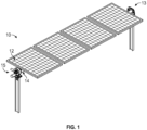
- the solar tracker system 10 generally includes an array of solar modules 12 (e.g., PV modules), a torque tube 14, and mounting brackets 100, 200, 300 for coupling the array of PV modules 12 to the torque tube 14.
- Each of the mounting brackets 100, 200, 300 may be oriented perpendicularly relative to the torque tube 14 and extend under each the PV modules 12.
- the torque tube 14 is rotatable about an axis to adjust an angular orientation of the PV modules 12 relative to the sun.
- the solar tracker system 10 includes a bearing housing assembly (BHA) 13 at one end and slew gear drive 15 at the opposite end.
- BHA bearing housing assembly
- the system 10 may include more than one torque tube 14, connected either to the slew gear drive 15 or to torque tube 14 via a clamp (not shown).
- the slew gear drive 15 may be located in the center of a plurality of torque tubes 14, or at one end of the connected torque tubes 14.
- a multiple actuator system may be used in the alternative to the slew gear drive 15.
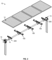
- Fig. 2 depicts three first mounting brackets 100, one second mounting bracket 200 and one third mounting bracket 300 being utilized to couple four PV modules 12 to the torque tube 14.
- a second mounting bracket 200 is mounted nearest the slew gear drive 15.
- a solar module 12 is mounted between the second mounting bracket 200 and a first mounting bracket 100. Any number of solar modules 12 may then be mounted between sets of first mounting brackets 100.
- a solar module is mounted between a first mounting bracket 100 and a third mounting bracket 300. This third mounting bracket 300 is positioned closest to the BHA 13.
- the first mounting bracket 100 has a generally rectangular shape.
- the solar module 12 can include side rails 12a including several mounting slots 12b.
- Mounting slots 12b of the side rails 12a are configured to receive the retaining tab 203 of the first mounting bracket 100.
- the retaining tab 203 is presented in more detail in FIG.7 .
- the mounting slots 12b can be oval in shape; however, it is contemplated that other shapes such as square or round may be utilized.
- the mounting slots 12b also provide the benefit of providing additional grounding through the metal to metal contact of the locking devices of the mounting brackets 100, 200, 300 and the side rails 12a of the solar modules 12.
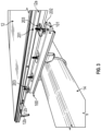
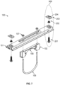
- an exemplary first mounting bracket 100 is illustrated and generally includes a first retainer assembly 500 disposed on the upper surface of the first mounting bracket 100.
- the first retainer assembly 500 is a spring clamp that engages the side rail 12a of a solar module 12.
- the first retainer assembly 500 of the first mounting bracket 100 is aligned to mate with one of the mounting slots 12b of the sidewall 12a of a solar module 12.
- the mounting tab 203 of the first retainer assembly 500 is now in an advantageous position to engage another solar module 12.
- the spring 202 of the first retainer assembly 500 keeps the bolt 201 from falling out when mating to a solar module 12.
- the mounting tab 203 and the solar module 12 are relatively secure, allowing for a second solar module 12 to be mated.
- the bolt 201 of the first retainer assembly 500 can be tightened to ensure that the solar modules 12 remain fixed to a first mounting bracket 100 as shown in FIG. 6 . Additional solar modules 12 may be secured to the next first mounting bracket 100 via the retainer assemblies 500 in the manner described above.
- an exploded view of an exemplary first mounting bracket 100 is illustrated and generally includes one or more retainer assemblies 500, a first clamp assembly 102, a U-bolt 106, and one or more nuts 107.
- a rail 101 of the mounting first bracket 100 is configured to receive a first clamp assembly 102.
- the first clamp assembly 102 includes a radius that is substantially the same radius as the torque tube 14.
- the first clamp assembly 102 may include a locking tab 108 that is configured to be received into one or more locking holes in the torque tube 14.
- the first clamp assembly 102 has a plurality of holes for receiving a U-bolt 106.
- the U-bolt 106 is then received through a plurality of holes in the rail 101 and fastened using nuts 107, to frictionally engage the torque tube 14. It is contemplated that other locking devices known in the art, for example clips or fastening pins, may be used to secure the U-bolt 106.
- the first mounting bracket 100 includes one or more first retainer assemblies 500 configured for retaining solar modules 12.
- the first retainer assembly 500 includes a through bolt 201, a washer and spring assembly 202, a retaining tab 203, and a nut 204.
- the through bolt 201 is inserted through the bottom surface of the first mounting bracket 100 through a hole in the rail 101, such that the head of the through bolt 201 rests against the bottom surface of the rail 101. It is contemplated that a serrated or ribbed flange head on the through bolt 201 may be used to assist in locking of the nut 204. It is contemplated that the hole can be a slot or any other advantageous shape.
- the washer and spring assembly 202 and the retaining tab 203 are then loaded onto the protruding portion of the through bolt 201, where the nut 204 is tightened to the through bolt 201.
- the force of the spring assembly 202 causes the head of the bolt 201 to rest against the bottom surface of the rail 101. This preload assists in retaining solar modules during installation before being tightened in place via the nut 204.
- the retaining tab 203 could incorporate threads so that a separate nut 204 would not be needed. It is contemplated that the retaining tab 203 can have a scalloped shape to assist in grabbing the edge of the mounting slot 12b in the solar module 12. In another embodiment, the retaining tab 203 may utilize other captive shapes.
- the washer 202b may be slotted to assist in locking the spring 202a so that it does not fall through the hole in the top surface of the rail 101. It is contemplated that the washer 202b and spring 202a could be, for example, soldered or brazed together.
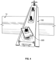
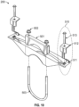
- an exemplary second mounting bracket 200 mounted to the torque tube 14 is illustrated.
- the second mounting bracket 200 is disposed on the torque tube 14 and located proximate to the slew gear drive 15 ( FIG. 2 ).
- a solar tracker system 10 will typically have one second mounting bracket 200 on each side of the slew gear drive 15.
- a first mounting bracket 100 is disposed approximately the distance of the width of one of the solar modules 12 along the longitudinal axis of the torque tube 14.
- the second mounting bracket 200 has a plurality of second retainer assemblies 510 disposed on the upper surface of the second mounting bracket 200.
- the second retainer assemblies 510 are spaced from one another along the longitudinal axis of the second mounting bracket 200.
- each of the retainer assemblies 510 include a catch 511 positioned on the second mounting bracket 200 such that it is received in the slot 12b of a solar module 12 from an interior direction when the solar module 12 is placed on the second mounting bracket 200.
- the catch 511 prevents movement of the solar module 12 in the direction of the closed portion of catch 511.
- each of the second retainer assemblies 510 also includes a clamp 512 and a thru bolt 513 that clamps on the top of a solar module 12.
- the clamp 512 holds the top of the solar module side rail 12a and is fixed in position by the tightening of bolt 513.
- the catch 511 can be a j-hook, an upward pointing pin, a tab or other structures to secure the solar module side rail 12a.
- the second mounting bracket 200 is configured for integrating with a torque bar clamp 501.
- the torque bar clamp 501 is configured to provide frictional engagement with the torque tube 14.
- the second mounting bracket 200 includes a plurality of mounting holes configured for integrating with the second retainer assembly 510 and the torque bar clamp 501.
- the second mounting bracket 200 is substantially the same radius as the torque tube 14 and is configured to provide frictional engagement with the torque tube 14.
- the second mounting bracket 200 may include a locking tab that is configured to be received into one or more locking holes in the torque tube 14.
- the second mounting bracket 200 has a plurality of holes for receiving a U-bolt 503 and fastened using nuts 502, to frictionally engage the torque tube 14.
- the torque tube 14 is sandwiched between the U-bolt 503 and the torque bar clamp 501. Where the tightening of the nuts 502 allow the U-bolt 503 and the torque bar clamp 501 to provide clamping force around the torque tube 14. It is contemplated that other locking devices known in the art, for example clips or fastening pins, may be used to secure the U-bolt 503.
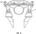
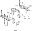
- the third mounting bracket 300 is configured for integrating with a torque bar clamp 301. It is contemplated that the structure for the third mounting bracket 300 can be the same as the second mounting bracket 200 except for the torque bar clamp 301.
- the torque bar clamp 301 can be centrally located on the third mounting bracket 300.
- the torque bar clamp is configured to provide frictional engagement with the torque tube 14.
- the third mounting bracket 300 includes a plurality of mounting holes configured for integrating with one or more second retainer assemblies 510 and the torque bar clamp 301. It is contemplated that the plurality of mounting holes can be round, slotted, or any other advantageous shape for mounting a bolt or other retaining mechanism.
- the torque bar clamp 301 of the third mounting bracket 300 is configured for integrating with a bearing housing assembly (BHA) 13 through use of a connecting rod 315.
- the connecting rod 315 can have a tab on the end that is received by an opening in the side of torque bar clamp 301 of the third mounting bracket 300.
- a solar tracking system 10 can have a third mounting bracket 300 mounted on both or either side of a BHA 13.
- the third mounting bracket 300 includes a radius that matches the torque tube 14 and is configured to provide frictional engagement with the torque tube 14.
- the third mounting bracket 300 may include a locking tab that is configured to be received into one or more locking holes in the torque tube 14.
- the third mounting bracket 300 has a plurality of holes for receiving a U-bolt 303 and fastened using nuts 302, to frictionally engage the torque tube 14.
- the U-bolt 301 passes through the holes in the bottom surface of the third mounting bracket 300 and through the torque bar clamp 301 and is fastened using nuts 302. This clamping provides frictional engagement with the torque tube 14. It is contemplated that other locking devices known in the art, for example clips or fastening pins, may be used to secure the U-bolt 503.
- the third mounting bracket 300 connects to the solar module 12 in a similar manner as the second mounting bracket 200 through use of the second retainer assembly 510. That is, after the catch 511 is mounted from the interior direction of the solar module 12, the clamp 512 holds the top of the solar module side rail 12a and the solar module 12 is fixed in position by the tightening of the bolts 513. Mounting a solar module 12 to the third mounting bracket 300 can be either the first or the last mounting of a solar module during assembly.
- the mounting brackets 100, 200, 300 may be used in any suitable solar module mounting system, such as a fixed solar system or the like to improve the efficiency in the installation of the solar modules
- the fasteners described herein may be any suitable fastening mechanism, including, but not limited to, adhesives, hinges, clips, ties, straps, belts, tapes and/or fabric hook-and-loop fasteners.
- parallel and perpendicular are understood to include relative configurations that are substantially parallel and substantially perpendicular up to about + or - 30 degrees from true parallel and true perpendicular.
Landscapes
- Engineering & Computer Science (AREA)
- Life Sciences & Earth Sciences (AREA)
- Sustainable Development (AREA)
- Physics & Mathematics (AREA)
- Sustainable Energy (AREA)
- Thermal Sciences (AREA)
- Chemical & Material Sciences (AREA)
- Combustion & Propulsion (AREA)
- Mechanical Engineering (AREA)
- General Engineering & Computer Science (AREA)
- Photovoltaic Devices (AREA)
- Roof Covering Using Slabs Or Stiff Sheets (AREA)
Applications Claiming Priority (3)
| Application Number | Priority Date | Filing Date | Title |
|---|---|---|---|
| US15/971,522 US11502638B2 (en) | 2018-05-04 | 2018-05-04 | Solar module mounting system |
| PCT/US2019/030648 WO2019213554A1 (en) | 2018-05-04 | 2019-05-03 | Solar module mounting system |
| EP19796953.8A EP3788309B1 (de) | 2018-05-04 | 2019-05-03 | Montagesystem für solarmodul |
Related Parent Applications (2)
| Application Number | Title | Priority Date | Filing Date |
|---|---|---|---|
| EP19796953.8A Division-Into EP3788309B1 (de) | 2018-05-04 | 2019-05-03 | Montagesystem für solarmodul |
| EP19796953.8A Division EP3788309B1 (de) | 2018-05-04 | 2019-05-03 | Montagesystem für solarmodul |
Publications (1)
| Publication Number | Publication Date |
|---|---|
| EP4227600A1 true EP4227600A1 (de) | 2023-08-16 |
Family
ID=68385553
Family Applications (2)
| Application Number | Title | Priority Date | Filing Date |
|---|---|---|---|
| EP23173962.4A Pending EP4227600A1 (de) | 2018-05-04 | 2019-05-03 | Solarmodul-montagesystem |
| EP19796953.8A Active EP3788309B1 (de) | 2018-05-04 | 2019-05-03 | Montagesystem für solarmodul |
Family Applications After (1)
| Application Number | Title | Priority Date | Filing Date |
|---|---|---|---|
| EP19796953.8A Active EP3788309B1 (de) | 2018-05-04 | 2019-05-03 | Montagesystem für solarmodul |
Country Status (7)
| Country | Link |
|---|---|
| US (3) | US11502638B2 (de) |
| EP (2) | EP4227600A1 (de) |
| CN (2) | CN112105874B (de) |
| AU (2) | AU2019262608B2 (de) |
| ES (1) | ES2956282T3 (de) |
| PL (1) | PL3788309T3 (de) |
| WO (1) | WO2019213554A1 (de) |
Families Citing this family (45)
| Publication number | Priority date | Publication date | Assignee | Title |
|---|---|---|---|---|
| DE112013005890T5 (de) | 2012-12-10 | 2015-09-10 | Nextracker Inc. | Horizontaler ausgeglichener Solarnachführer |
| US10008975B2 (en) | 2012-12-10 | 2018-06-26 | Nextracker Inc. | Clamp assembly for solar tracker |
| US9766319B2 (en) | 2012-12-10 | 2017-09-19 | Nextracker Inc. | Off-set drive assembly for solar tracker |
| US9466749B1 (en) * | 2012-12-10 | 2016-10-11 | Nextracker Inc. | Balanced solar tracker clamp |
| US11271518B2 (en) * | 2018-11-08 | 2022-03-08 | OMCO Solar, LLC | Mounting bracket for mounting photovoltaic modules to torque tube beam |
| US11223320B2 (en) * | 2019-03-12 | 2022-01-11 | Chandramouli Vaidyanathan | Solar panel flat roof mounting apparatus and method |
| US10903784B2 (en) * | 2019-03-21 | 2021-01-26 | Ojjo, Inc. | Moment optimized truss foundations for single-axis trackers |
| US11522489B2 (en) * | 2019-04-01 | 2022-12-06 | Unirac Inc. | Bonding clamp as photovoltaic module mounting equipment |
| USD973015S1 (en) | 2019-04-01 | 2022-12-20 | Unirac Inc. | Bonding clamp |
| US11569780B2 (en) * | 2020-03-17 | 2023-01-31 | Sun And Steel Solar Llc | Purlin system for solar module attachment |
| US20220193927A1 (en) * | 2020-06-26 | 2022-06-23 | Rosendin Electric, Inc. | Bracket usable for solar panel module installation |
| EP4197099A4 (de) * | 2020-08-17 | 2024-12-25 | Nextracker LLC | Mehrwandige verbindung über pfeiler |
| US20220115981A1 (en) * | 2020-10-08 | 2022-04-14 | The Regents Of The University Of Colorado, A Body Corporate | Systems and methods for conserving thermal and electrical energy usage in buildings and houses |
| ES1259619Y (es) * | 2020-10-28 | 2021-04-16 | Gomez Lucio Ayllon | Soporte de modulos fotovoltaicos de seguidor solar |
| CN114928320A (zh) * | 2021-02-11 | 2022-08-19 | 加拿大太阳能(美国)有限公司 | 太阳能电池板支架系统 |
| US11962269B2 (en) | 2021-02-24 | 2024-04-16 | Array Technologies, Inc. | Low-profile backrail module clamp |
| WO2022183204A1 (en) | 2021-02-24 | 2022-09-01 | Array Technologies, Inc. | Snap-lock photovoltaic module mounting system |
| US20220271706A1 (en) * | 2021-02-24 | 2022-08-25 | Array Technologies, Inc. | Snap-lock photovoltaic module mounting system |
| WO2022192910A1 (en) | 2021-03-11 | 2022-09-15 | Array Technologies, Inc. | Stowing of photovoltaic modules for hail mitigation |
| US11999284B2 (en) | 2021-09-01 | 2024-06-04 | Terabase Energy, Inc. | Solar table mobile transport |
| US12323093B2 (en) * | 2021-12-29 | 2025-06-03 | Unirac, Inc. | Photovoltaic module support system and mount assembly |
| US20230327602A1 (en) * | 2022-04-06 | 2023-10-12 | Nextracker Llc | Improved c-channel for solar tracker |
| US11984842B2 (en) * | 2022-05-09 | 2024-05-14 | FTC Solar, Inc. | Solar tracker systems and methods including a rail assembly |
| WO2023218486A1 (en) * | 2022-05-11 | 2023-11-16 | Kiran Shah | Flexible positioning and locking system for solar modules mountable on torque tubes in solar trackers |
| WO2024000064A1 (en) * | 2022-06-26 | 2024-01-04 | Nyoka Design Corp. | Fluid-activated biodegradable bioluminescent glowing apparatus, compositions, kits, methods, and systems |
| US12074559B2 (en) * | 2022-08-01 | 2024-08-27 | Array Tech, Inc. | Photovoltaic module mount |
| US11938576B1 (en) * | 2022-12-20 | 2024-03-26 | Terabase Energy, Inc. | Systems and methods for threading a torque tube through U-bolt and module rail devices |
| US20240235470A1 (en) | 2023-01-09 | 2024-07-11 | Sarcos Corp. | Auto-Engaging Electrical Connections for Solar Panels |
| US20240266993A1 (en) * | 2023-02-06 | 2024-08-08 | Nevados Engineering, Inc. | Variable terrain solar tracker |
| CN116248033B (zh) * | 2023-03-08 | 2023-12-05 | 浙江川达新能源股份有限公司 | 一种光伏支架追踪系统 |
| US12476579B2 (en) | 2023-03-20 | 2025-11-18 | Nextracker Llc | Solar module rail couplings for solar tracker |
| US12466066B2 (en) | 2023-05-04 | 2025-11-11 | Sarcos Corp. | Solar panel dispensing device with vertical solar panel hopper loading and dispensing |
| AU2024345875A1 (en) * | 2023-09-22 | 2026-04-02 | Gridworks, Inc. | Pv module conveyance system and methods |
| WO2025096457A1 (en) * | 2023-11-03 | 2025-05-08 | Array Tech, Inc. | Photovoltaic module mounting rails |
| US12542513B2 (en) | 2024-01-08 | 2026-02-03 | Sarcos Corp. | Torque tube clamps for automated solar panel installation |
| US20250226791A1 (en) * | 2024-01-08 | 2025-07-10 | Sarcos Corp. | Solar Panel Mounting Systems and Methods |
| US12570001B2 (en) | 2024-01-08 | 2026-03-10 | Sarcos Corp. | Support clamp installation vehicles as part of a solar panel installation system for a solar tracking system |
| US20250224148A1 (en) * | 2024-01-08 | 2025-07-10 | Sarcos Corp. | Solar Panel Installation Alignment Systems |
| US20250233552A1 (en) * | 2024-01-16 | 2025-07-17 | Nextracker Llc | Solar module frame couplings |
| PL447583A1 (pl) * | 2024-01-23 | 2025-07-28 | Enson Spółka Z Ograniczoną Odpowiedzialnością | System i sposób mocowania paneli fotowoltaicznych do konstrukcji wsporczej |
| US20250247046A1 (en) * | 2024-01-25 | 2025-07-31 | Nextracker Llc | Solar module frames |
| WO2025171215A1 (en) * | 2024-02-07 | 2025-08-14 | Array Tech, Inc. | Mounting rail |
| DE102024120170A1 (de) * | 2024-07-15 | 2026-01-15 | Robert Zimmermann | Solarmodulhaltevorrichtung |
| US20260100672A1 (en) * | 2024-10-07 | 2026-04-09 | Nextracker Llc | Bearing housing adaptor for solar tracker |
| CN120498330B (zh) * | 2025-05-14 | 2025-11-18 | 恒隆通信技术有限公司 | 一种光储充集成装置 |
Citations (4)
| Publication number | Priority date | Publication date | Assignee | Title |
|---|---|---|---|---|
| US20110179606A1 (en) * | 2010-01-22 | 2011-07-28 | Thomas & Betts International, Inc. | Panel clamp |
| US20150129517A1 (en) * | 2013-11-14 | 2015-05-14 | Ecolibrium Solar, Inc. | Modular Sloped Roof Solar Mounting System |
| CN107482998A (zh) * | 2016-06-08 | 2017-12-15 | 索亿斯(厦门)设备科技有限公司 | 可调式太阳能支架 |
| US20180062569A1 (en) * | 2016-09-01 | 2018-03-01 | Sunpower Corporation | Photovoltiac module mounting assembly having a pin constraint |
Family Cites Families (17)
| Publication number | Priority date | Publication date | Assignee | Title |
|---|---|---|---|---|
| US7807918B2 (en) * | 2003-03-10 | 2010-10-05 | Sunpower Corporation, Systems | Modular shade system |
| CN2758572Y (zh) * | 2003-05-27 | 2006-02-15 | 小川信夫 | 架台用固定辅助件 |
| FR2945609B1 (fr) * | 2009-05-12 | 2013-03-29 | Avancis Gmbh & Co Kg | Dispositif de fixation et procede de montage de modules solaires. |
| US8776454B2 (en) * | 2011-04-05 | 2014-07-15 | Michael Zuritis | Solar array support structure, mounting rail and method of installation thereof |
| US9091461B2 (en) | 2011-04-27 | 2015-07-28 | Blue Sunny Skies Llc | Grounding system for photovoltaic arrays |
| US8567134B1 (en) * | 2012-06-29 | 2013-10-29 | Sunpower Corporation | Snap-in and progressive locking photovoltaic module |
| US9395104B2 (en) | 2012-09-28 | 2016-07-19 | Sunpower Corporation | Integrated torque coupling and mount |
| FR2996384A1 (fr) | 2012-10-01 | 2014-04-04 | Benoit Rouviere | Dispositif de montage et de fixation de panneaux solaires sur une toiture. |
| EP2917430B1 (de) | 2012-11-08 | 2025-07-02 | Cameron, D. Kevin | Gebäudestruktur mit einem dach, auf dem ausrüstung montiert werden kann |
| US10075125B2 (en) * | 2012-12-10 | 2018-09-11 | Nextracker Inc. | Self-powered solar tracker apparatus |
| US9347691B2 (en) * | 2013-02-26 | 2016-05-24 | Solarcity Corporation | Torque Tube Mounted Photovoltaic Apparatus, System, and Method |
| US9531319B2 (en) | 2013-12-23 | 2016-12-27 | Sunpower Corporation | Clamps for solar systems |
| US10804837B2 (en) | 2016-03-25 | 2020-10-13 | Sunpower Corporation | Sun tracking solar energy collection system and method of assembly |
| US10622937B2 (en) | 2016-04-06 | 2020-04-14 | Solarcity Corporation | Spring latch saddle connector for solar tracker |
| US10587216B2 (en) | 2016-04-20 | 2020-03-10 | Solarcity Corporation | Over-center under photovoltaic module clamp |
| US10298172B2 (en) | 2016-09-01 | 2019-05-21 | Sunpower Corporation | Photovoltaic module mounting assembly having a retainer |
| US20190068112A1 (en) * | 2017-08-31 | 2019-02-28 | QuantPower | Tracker system |
-
2018
- 2018-05-04 US US15/971,522 patent/US11502638B2/en active Active
-
2019
- 2019-05-03 AU AU2019262608A patent/AU2019262608B2/en active Active
- 2019-05-03 ES ES19796953T patent/ES2956282T3/es active Active
- 2019-05-03 CN CN201980030332.5A patent/CN112105874B/zh active Active
- 2019-05-03 EP EP23173962.4A patent/EP4227600A1/de active Pending
- 2019-05-03 EP EP19796953.8A patent/EP3788309B1/de active Active
- 2019-05-03 CN CN202210824140.5A patent/CN115065315A/zh active Pending
- 2019-05-03 WO PCT/US2019/030648 patent/WO2019213554A1/en not_active Ceased
- 2019-05-03 PL PL19796953.8T patent/PL3788309T3/pl unknown
-
2021
- 2021-10-25 AU AU2021257887A patent/AU2021257887B2/en active Active
-
2022
- 2022-11-15 US US17/987,601 patent/US11979107B2/en active Active
-
2024
- 2024-04-12 US US18/633,770 patent/US20240258958A1/en active Pending
Patent Citations (4)
| Publication number | Priority date | Publication date | Assignee | Title |
|---|---|---|---|---|
| US20110179606A1 (en) * | 2010-01-22 | 2011-07-28 | Thomas & Betts International, Inc. | Panel clamp |
| US20150129517A1 (en) * | 2013-11-14 | 2015-05-14 | Ecolibrium Solar, Inc. | Modular Sloped Roof Solar Mounting System |
| CN107482998A (zh) * | 2016-06-08 | 2017-12-15 | 索亿斯(厦门)设备科技有限公司 | 可调式太阳能支架 |
| US20180062569A1 (en) * | 2016-09-01 | 2018-03-01 | Sunpower Corporation | Photovoltiac module mounting assembly having a pin constraint |
Also Published As
| Publication number | Publication date |
|---|---|
| AU2021257887B2 (en) | 2023-04-27 |
| CN115065315A (zh) | 2022-09-16 |
| EP3788309A4 (de) | 2022-01-05 |
| AU2019262608A1 (en) | 2020-11-12 |
| AU2019262608B2 (en) | 2021-09-16 |
| WO2019213554A1 (en) | 2019-11-07 |
| US20230070097A1 (en) | 2023-03-09 |
| ES2956282T3 (es) | 2023-12-18 |
| AU2021257887A1 (en) | 2021-11-18 |
| EP3788309B1 (de) | 2023-06-28 |
| PL3788309T3 (pl) | 2023-12-27 |
| US20190341878A1 (en) | 2019-11-07 |
| US20240258958A1 (en) | 2024-08-01 |
| US11502638B2 (en) | 2022-11-15 |
| CN112105874A (zh) | 2020-12-18 |
| EP3788309C0 (de) | 2023-06-28 |
| EP3788309A1 (de) | 2021-03-10 |
| US11979107B2 (en) | 2024-05-07 |
| CN112105874B (zh) | 2022-07-22 |
Similar Documents
| Publication | Publication Date | Title |
|---|---|---|
| AU2021257887B2 (en) | Solar Module Mounting System | |
| US20130140416A1 (en) | Apparatus for Forming and Mounting a Photovoltaic Array | |
| US9998066B2 (en) | Method and apparatus for forming and mounting a photovoltaic array | |
| US9447801B2 (en) | Apparatus for forming and mounting a photovoltaic array | |
| US20140182662A1 (en) | Method and Apparatus for Forming and Mounting a Photovoltaic Array | |
| US8702335B2 (en) | Module clamp and fastener apparatus | |
| US12567827B2 (en) | Securing device for solar panel | |
| US20140060626A1 (en) | Interchangeable mounting system for rooftop solar energy installations | |
| US20240204716A1 (en) | Photovoltaic module clamp assembly | |
| EP3099984B1 (de) | Photovoltaisches solarmodulspannsystem und solarcarport | |
| US20250373195A1 (en) | Solar module frame coupling assemblies | |
| US20240372506A1 (en) | Module rail assembly | |
| US12057802B2 (en) | Tabbed structural bracket | |
| US12573978B2 (en) | Mounting rails | |
| US20260058599A1 (en) | Pin locking rail for solar module frame coupling | |
| WO2025155442A1 (en) | Solar module frame couplings |
Legal Events
| Date | Code | Title | Description |
|---|---|---|---|
| PUAI | Public reference made under article 153(3) epc to a published international application that has entered the european phase |
Free format text: ORIGINAL CODE: 0009012 |
|
| STAA | Information on the status of an ep patent application or granted ep patent |
Free format text: STATUS: THE APPLICATION HAS BEEN PUBLISHED |
|
| AC | Divisional application: reference to earlier application |
Ref document number: 3788309 Country of ref document: EP Kind code of ref document: P |
|
| AK | Designated contracting states |
Kind code of ref document: A1 Designated state(s): AL AT BE BG CH CY CZ DE DK EE ES FI FR GB GR HR HU IE IS IT LI LT LU LV MC MK MT NL NO PL PT RO RS SE SI SK SM TR |
|
| P01 | Opt-out of the competence of the unified patent court (upc) registered |
Effective date: 20231012 |
|
| STAA | Information on the status of an ep patent application or granted ep patent |
Free format text: STATUS: REQUEST FOR EXAMINATION WAS MADE |
|
| 17P | Request for examination filed |
Effective date: 20240202 |
|
| RBV | Designated contracting states (corrected) |
Designated state(s): AL AT BE BG CH CY CZ DE DK EE ES FI FR GB GR HR HU IE IS IT LI LT LU LV MC MK MT NL NO PL PT RO RS SE SI SK SM TR |
|
| GRAP | Despatch of communication of intention to grant a patent |
Free format text: ORIGINAL CODE: EPIDOSNIGR1 |
|
| RIC1 | Information provided on ipc code assigned before grant |
Ipc: F24S 25/632 20180101AFI20260218BHEP Ipc: F24S 30/425 20180101ALI20260218BHEP Ipc: H02S 20/32 20140101ALI20260218BHEP Ipc: H02S 30/10 20140101ALI20260218BHEP |
|
| STAA | Information on the status of an ep patent application or granted ep patent |
Free format text: STATUS: GRANT OF PATENT IS INTENDED |
|
| RAP3 | Party data changed (applicant data changed or rights of an application transferred) |
Owner name: NEXTPOWER LLC |
|
| RIN1 | Information on inventor provided before grant (corrected) |
Inventor name: WATSON, TYLER Inventor name: LAWSON, DENNIS MARVIN Inventor name: HOANG, THAO THANH Inventor name: HABIB, PAUL DANIEL |