EP4227621A1 - Trocknungsvorrichtung und elektrodenplattenherstellungsvorrichtung - Google Patents
Trocknungsvorrichtung und elektrodenplattenherstellungsvorrichtung Download PDFInfo
- Publication number
- EP4227621A1 EP4227621A1 EP23151864.8A EP23151864A EP4227621A1 EP 4227621 A1 EP4227621 A1 EP 4227621A1 EP 23151864 A EP23151864 A EP 23151864A EP 4227621 A1 EP4227621 A1 EP 4227621A1
- Authority
- EP
- European Patent Office
- Prior art keywords
- oven section
- air
- air outlet
- oven
- tuyeres
- Prior art date
- Legal status (The legal status is an assumption and is not a legal conclusion. Google has not performed a legal analysis and makes no representation as to the accuracy of the status listed.)
- Granted
Links
Images

Classifications
-
- F—MECHANICAL ENGINEERING; LIGHTING; HEATING; WEAPONS; BLASTING
- F26—DRYING
- F26B—DRYING SOLID MATERIALS OR OBJECTS BY REMOVING LIQUID THEREFROM
- F26B3/00—Drying solid materials or objects by processes involving the application of heat
- F26B3/02—Drying solid materials or objects by processes involving the application of heat by convection, i.e. heat being conveyed from a heat source to the materials or objects to be dried by a gas or vapour, e.g. air
- F26B3/04—Drying solid materials or objects by processes involving the application of heat by convection, i.e. heat being conveyed from a heat source to the materials or objects to be dried by a gas or vapour, e.g. air the gas or vapour circulating over or surrounding the materials or objects to be dried
-
- F—MECHANICAL ENGINEERING; LIGHTING; HEATING; WEAPONS; BLASTING
- F26—DRYING
- F26B—DRYING SOLID MATERIALS OR OBJECTS BY REMOVING LIQUID THEREFROM
- F26B21/00—Arrangements for supplying or controlling air or other gases for drying solid materials or objects
- F26B21/50—Ducting arrangements from the source of air or other gases to the materials or objects being dried
-
- B—PERFORMING OPERATIONS; TRANSPORTING
- B05—SPRAYING OR ATOMISING IN GENERAL; APPLYING FLUENT MATERIALS TO SURFACES, IN GENERAL
- B05D—PROCESSES FOR APPLYING FLUENT MATERIALS TO SURFACES, IN GENERAL
- B05D3/00—Pretreatment of surfaces to which liquids or other fluent materials are to be applied; After-treatment of applied coatings, e.g. intermediate treating of an applied coating preparatory to subsequent applications of liquids or other fluent materials
- B05D3/02—Pretreatment of surfaces to which liquids or other fluent materials are to be applied; After-treatment of applied coatings, e.g. intermediate treating of an applied coating preparatory to subsequent applications of liquids or other fluent materials by baking
- B05D3/0254—After-treatment
- B05D3/0272—After-treatment with ovens
-
- F—MECHANICAL ENGINEERING; LIGHTING; HEATING; WEAPONS; BLASTING
- F26—DRYING
- F26B—DRYING SOLID MATERIALS OR OBJECTS BY REMOVING LIQUID THEREFROM
- F26B3/00—Drying solid materials or objects by processes involving the application of heat
- F26B3/02—Drying solid materials or objects by processes involving the application of heat by convection, i.e. heat being conveyed from a heat source to the materials or objects to be dried by a gas or vapour, e.g. air
-
- Y—GENERAL TAGGING OF NEW TECHNOLOGICAL DEVELOPMENTS; GENERAL TAGGING OF CROSS-SECTIONAL TECHNOLOGIES SPANNING OVER SEVERAL SECTIONS OF THE IPC; TECHNICAL SUBJECTS COVERED BY FORMER USPC CROSS-REFERENCE ART COLLECTIONS [XRACs] AND DIGESTS
- Y02—TECHNOLOGIES OR APPLICATIONS FOR MITIGATION OR ADAPTATION AGAINST CLIMATE CHANGE
- Y02E—REDUCTION OF GREENHOUSE GAS [GHG] EMISSIONS, RELATED TO ENERGY GENERATION, TRANSMISSION OR DISTRIBUTION
- Y02E60/00—Enabling technologies; Technologies with a potential or indirect contribution to GHG emissions mitigation
- Y02E60/10—Energy storage using batteries
Definitions
- the present application relates to the technical field of batteries, and in particular to a drying device and an electrode plate manufacturing apparatus.
- the present application provides a drying device and an electrode plate manufacturing apparatus which can increase the production efficiency of batteries.
- a drying device for drying a material which comprises: a first oven section; a second oven section; and a third oven section, the first oven section, the second oven section and the third oven section being arranged sequentially in a movement direction of the material, wherein the second oven section has a larger air outlet area than the first oven section, and the first oven section has a larger air outlet area than the third oven section, such that the air speed of the first oven section is greater than that of the second oven section, and the air speed of the third oven section is greater than that of the first oven section.
- the material moves and passes through the first oven section, the second oven section and the third oven section sequentially.
- the first oven section, the second oven section and the third oven section each provide an airflow for the material to dry a film layer on a surface of the material. Since the first oven section, the second oven section and the third oven section are supplied with air from the same air source, by adjusting respective air outlet areas of the first oven section, the second oven section and the third oven section, each oven section is allowed to provide an airflow at a different air speed to achieve different drying effects.
- the first oven section provides an airflow at a high air speed to quickly preheat the material.
- the film layer on the surface of the material Before entering the first oven section, the film layer on the surface of the material is wet, and the wet film layer can be quickly preheated by the airflow at the high air speed in the first oven section with no damages to the film layer on the surface of the material.
- the second oven section provides an airflow at a low air speed to the material, which can provide slow evaporation for the material. By means of the airflow at the low air speed, a solvent in the wet film layer can be evaporated and damages to the film layer caused by an excessive air speed can be prevented.
- the third oven section is an oven section with the highest air speed among the three oven sections.
- the film layer on the material has been formed in the second oven section, a high-speed airflow is provided to the material, which can quickly dry the material, such that the wet film layer is formed into a dry film layer, thereby increasing the drying efficiency of the material and increasing the production efficiency of batteries.
- the first oven section has an air speed of less than 15 m/s
- the second oven section has an air speed of less than 10 m/s
- the third oven section has an air speed of 15-30 m/s.
- the air speeds of the first oven section, the second oven section and the third oven section are defined, such that it is possible to increase the drying efficiency of the material as much as possible while ensuring that the film layer of the material is not damaged, thereby increasing the production efficiency of the batteries while ensuring the quality of the batteries.
- the first oven section has a plurality of first tuyeres
- the second oven section has a plurality of second tuyeres
- the third oven section has a plurality of third tuyeres; and both of the first tuyeres and the second tuyeres have a larger air outlet area than the third tuyeres.
- Provision of the plurality of identical tuyeres in each of the oven sections can ensure the uniformity of air outlet of this oven section, such that the airflow can fully act on the material and thus the drying effect of each oven section is ensured.
- the air outlet area of the third tuyeres are set to be smaller than the air outlet areas of the first tuyeres and the second tuyeres in such a way that it can effectively ensure that the third oven section provides an airflow at a higher speed to the material than the first oven section and the second oven section to ensure quick drying of the material and to increase the drying efficiency of the material.
- the number of the tuyeres of each of the oven sections is not less than 15 per 5 m, and the center-to-center distance between two adjacent tuyeres is not greater than 0.3 m.
- the number of tuyeres provided per 5 m is not less than 15, and the center-to-center distance between two adjacent tuyeres is not greater than 0.3 m, which can ensure the uniformity of the air outlet in the oven section and ensure that the airflow can effectively cover the material to ensure the drying quality and efficiency of the material.
- the air outlet area of the first oven section is not less than 255,000 mm 2 /5 m; the air outlet area of the second oven section is not less than 375,000 mm 2 /5 m; and the air outlet area of the third oven section is not less than 84,000 mm 2 /5 m.
- a minimum specific value of the air outlet area of each oven section is defined, and the air outlet area of the tuyeres can be calculated in the case of the minimum number of tuyeres, and thus the practicability of this scheme is improved to ensure that the drying device can complete the drying operation smoothly and efficiently.
- the volume of air of the first oven section accounts for 30-60% of the total volume of air of the drying device
- the volume of air of the second oven section accounts for 15-35% of the total volume of air of the drying device
- the volume of air of the third oven section accounts for 20-40% of the total volume of air of the drying device.
- the air source provides a respective volume of air corresponding to the numerical value to each oven section.
- the oven section is allowed to provide an airflow at a different speed to achieve different drying effects, increasing the drying efficiency of the material while ensuring no damages to the film layer.
- the first tuyeres and the second tuyeres each comprise an air outlet face structure
- the air outlet face structure comprises a boosting part and an air outlet part which are superposed in an air outlet direction with a gap therebetween
- the boosting part is formed with a plurality of first slits at intervals
- the air outlet part is formed with a plurality of second slits, the first slits being staggered with the second slits.
- the first tuyeres and the second tuyeres each comprise an air outlet face structure, and the air outlet face structure has the advantages of a simple structure and being easy to manufacture, which can effectively reduce the manufacturing cost of the drying device.
- the airflow passes through the first slits and the gap between the boosting part and the air outlet part, and is ejected from the second slits, which can improve the uniformity of the air outlet of the tuyeres, prevent damages to the film layer of the electrode plate due to turbulences, and ensure the drying effect of the material.
- the boosting part comprises a first frame and a plurality of first connecting portions arranged in the first frame, each of the first connecting portions is connected to the first frame at two ends, and the first slits are formed between two adjacent ones of the first connecting portions; and the air outlet part comprises a second frame and a plurality of second connecting portions arranged in the second frame, each of the second connecting portions is connected to the second frame at two ends, and the second slits are formed between two adjacent ones of the second connecting portions.
- the boosting part has a simple structure and is easy to manufacture, and the plurality of first connecting portions are arranged at intervals in the first frame to form the first slits, which effectively reduces the manufacturing difficulty of the boosting part.
- the air outlet part has a simple structure and is easy to manufacture.
- the plurality of second connecting portions are arranged at intervals in the second frame to directly form the second slits, which can effectively reduce the manufacturing difficulty of the boosting part.
- first connecting portions and/or the second connecting portions are hollow structures.
- the first connecting portions and/or the second connecting portions are configured as hollow structures, such that the mass of the first tuyeres and the second tuyeres can be effectively reduced, and the material cost of the first tuyeres and the second tuyeres can be saved.
- the present application further provides an electrode plate manufacturing apparatus, comprising a coating device for coating a slurry on a surface of the electrode plate; and the drying device according to the first aspect, in a movement direction of the electrode plate, the drying device being disposed downstream of the coating device for drying the slurry on the electrode plate.
- the terms “mount”, “connected”, “connect”, or “attach” should be interpreted in a broad sense unless explicitly defined and limited otherwise. For example, they may be a fixed connection, a detachable connection, or an integral connection; or may be a direct connection, an indirect connection by means of an intermediate medium, or internal communication between two elements.
- the specific meaning of the foregoing terms in the present application may be understood according to specific circumstances.
- a plurality of appearing in the present application means two or more (including two).
- a battery cell may include a lithium-ion secondary battery, a lithium-ion primary battery, a lithium-sulfur battery, a sodium/lithium- ion battery, a sodium-ion battery or a magnesium-ion battery, etc., which is not limited by the embodiments of the present application.
- a battery mentioned in the embodiments of the present application refers to a single physical module including one or more battery cells to provide a higher voltage and capacity.
- the battery mentioned in the present application may include a battery module, a battery pack, etc.
- the battery generally includes a case for enclosing one or more battery cells. The case can prevent liquid or other foreign matters from affecting charging or discharging of a battery monomer.
- the core member of the battery that can implement a repeated charge and discharge function is an electrode assembly in the battery cell.
- the electrode assembly comprises an electrode plate and a separator, the electrode plate including a positive electrode plate and a negative electrode plate.
- the separator is usually disposed between the positive electrode plate and the negative electrode plate for insulation of the positive electrode plate from the negative electrode plate, and the separator may be made of polypropylene (PP), polyethylene (PE), etc.
- the battery cell operates mainly by relying on movements of metal ions between the positive electrode plate and the negative electrode plate.
- the electrode plate comprises a current collector and an active material layer.
- the current collector has a coating area coated with an active material layer and an uncoated area not coated with an active material layer in a width direction of the electrode plate.
- the current collector can be metal foil, such as copper foil, aluminum foil, and the like.
- a process for preparation of the electrode plate comprises a coating procedure in which a stirred slurry (i.e., the active material in the form of a slurry) is evenly applied on the current collector to form a film layer, and a drying procedure in which the film layer is dried to be a dry film layer so as to form the active material layer.
- the battery provides energy for the running of a vehicle body and the operations of various electrical components in the vehicle body.
- the battery technology is an important factor to their development. In the development of battery technology, how to increase the production efficiency of batteries is an urgent technical problem to be solved in the battery technology.
- the efficiency of the drying procedure is one of the key factors affecting the production efficiency of the battery.
- the inventors have found that an airflow at a fixed air speed is usually used to dry the electrode plate in an existing drying procedure.
- the film layer is unstable and is easily damaged by the airflow.
- the current collector is often dried at a lower fixed air speed, but the lower air speed impairs the drying efficiency of the electrode plate, which in turn influences the production efficiency of the battery.
- the inventor in order to increase the drying efficiency of the electrode plate to increase the production efficiency of the battery, the inventor has designed a drying device after in-depth studies, the drying device comprising: a first oven section; a second oven section; and a third oven section, the first oven section, the second oven section and the third oven section being arranged sequentially in a movement direction of the electrode plate, wherein the second oven section has a larger air outlet area than the first oven section, and the first oven section has a larger air outlet area than the third oven section, such that the air speed of the first oven section is greater than that of the second oven section, and the air speed of the third oven section is greater than that of the first oven section.
- the air speed of each of the oven sections can be adjusted by adjusting the air outlet area of the oven section, thus providing different drying effects for the electrode plate at different times.
- the first oven section provides an airflow at a high air speed to quickly preheat a film layer on the electrode plate.
- the wet film layer (at this moment, the film layer is a wet film layer) can be quickly preheated by the airflow at the high air speed with no damages to the film layer on the surface of the material.
- the second oven section provides an airflow at a low air speed to the electrode plate to provide slow evaporation for the electrode plate.
- the third oven section is an oven section with the highest air speed among the three oven sections. Since the film layer on the electrode plate has been formed after the evaporation in the second oven section, a high-speed airflow is provided to the electrode plate, which can quickly dry the electrode plate, such that the wet film layer is formed into a dry film layer, thereby increasing the drying efficiency of the electrode plate and increasing the production efficiency of the batteries.
- this scheme compared with a scheme of drying the electrode plate at a fixed lower air speed, this scheme provides airflows at different air speeds to the electrode plate according to different states of the film layer, which can increase the drying efficiency while ensuring the drying quality, thereby increasing the production efficiency of the batteries.
- the drying device disclosed in the embodiments of the present application can be used, but not limited to, in an electrode plate manufacturing apparatus or other apparatuses that need to dry materials.
- the material mentioned in the embodiments of the present application may refer to an electrode plate, or other materials that have a film layer on its surface and need to be dried.
- An electrode plate is used as an example of the material for illustration below.
- the technical solution described in the embodiments of the present application is applicable to an electrode plate manufacturing apparatus.
- the electrode plate manufacturing apparatus may refer to an apparatus that dries a current collector coated with an active material, or refer to an apparatus including a coating device and a drying device.
- the coating device is an apparatus that can evenly apply the active material to the current collector.
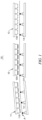
- FIG. 1 is a schematic diagram of a drying device 10 according to some embodiments of the present application.
- an electrode plate is denoted by the reference sign A.
- the drying device 10 for drying an electrode plate comprises a first oven section 11, a second oven section 12 and a third oven section 13.
- the first oven section 11, the second oven section 12 and the third oven section 13 are arranged sequentially in a movement direction of a material.
- the second oven section 12 has a larger air outlet area than the first oven section 11, and the first oven section 11 has a larger air outlet area than the third oven section 13, such that the air speed of the first oven section 11 is greater than that of the second oven section 12, and the air speed of the third oven section 13 is greater than that of the first oven section 11.
- the first oven section 11, the second oven section 12 and the third oven section 13 can be parts that provide airflows to the electrode plate. Air outlet faces of the first oven section 11, the second oven section 12 and the third oven section 13 face the electrode plate, such that the airflows from the respective air outlet faces are blown to the surface of the electrode plate, wherein the airflows may be hot airflows.
- the first oven section 11, the second oven section 12 and the third oven section 13 are supplied with air from the same air source.
- an oven device comprises or is connected to an air supply unit which supplies air to the first oven section 11, the second oven section 12 and the third oven section 13 simultaneously such that the total volume of air of the first oven section 11, the second oven section 12 and the third oven section 13 is fixed.
- the air outlet speed of each oven section can be adjusted based on its respective air outlet area to ensure a controllable air outlet speed of the oven section.
- a volume of air is equal to an air speed multiplied by an air outlet area, if the total volume of air is fixed, controlling the air outlet area of each oven section can control the air speed of the oven section.
- the electrode plate is supported by rollers 14 on a side away from the first oven section 11, the second oven section 12 and the third oven section 13, so as to realize the feeding movement of the electrode plate.
- the material moves and passes through the first oven section 11, the second oven section 12 and the third oven section 13 sequentially.
- the first oven section 11, the second oven section 12 and the third oven section 13 each provide an airflow for the material to dry a film layer on a surface of the material. Since the first oven section 11, the second oven section 12 and the third oven section 13 are supplied with air from the same air source, by adjusting respective air outlet areas of the first oven section 11, the second oven section 12 and the third oven section 13, each oven section is allowed to provide an airflow at a different air speed to the material to achieve different drying effects.
- the first oven section 11 provides an airflow at a high air speed to quickly preheat the electrode plate. At this moment, the film layer on the surface of the material is wet, and the wet film layer can be quickly preheated by the airflow at the high air speed with no damages to the film layer on the surface of the material to reduce the flowability of the film layer and improve the uniformity of the thickness of the film layer.
- the second oven section 12 provides an airflow at a low air speed to the electrode plate, which can provide slow evaporation for the electrode plate.
- the third oven section 13 is an oven section with the highest air speed among the three oven sections. Since the film layer on the electrode plate has been formed through the second oven section 12, a high-speed airflow is provided to the electrode plate, which can quickly dry the electrode plate, such that the wet film layer is formed into a dry film layer, thereby increasing the drying efficiency of the electrode plate and increasing the production efficiency of the batteries.
- this scheme compared with a scheme of drying the electrode plate at a fixed lower air speed, this scheme provides airflows at different air speeds to the electrode plate according to different states of the film layer, which can increase the drying efficiency while ensuring the drying quality, thereby increasing the production efficiency of the batteries.
- the first oven section 11 has an air speed of less than 15 m/s
- the second oven section 12 has an air speed of less than 10 m/s
- the third oven section 13 has an air speed of 15-30 m/s.
- the first oven section 11 having an air speed of less than 15 m/s means that the maximum speed at which the first oven section 11 blows an airflow to the electrode plate is less than 15 m/s and greater than the air speed of the second oven section 12, for example, 10 m/s.
- the second oven section 12 having an air speed of less than 10 m/s means that the speed at which the second oven section 12 blows an airflow to the electrode plate is less than 10 m/s, for example, 4 m/s.
- the third oven section 13 having an air speed of 15-30 m/s means that the speed at which the third oven section 13 blows an airflow to the electrode plate is between 15 m/s and 30 m/s, for example, 15 m/s, 20 m/s, 25 m/s s or 30 m/s, etc.
- the air speeds of the first oven section 11, the second oven section 12 and the third oven section 13 are defined, such that it is possible to increase the drying efficiency of the electrode plate as much as possible while ensuring that the film layer of the electrode plate is not damaged, thereby increasing the production efficiency of the batteries while ensuring the quality of the batteries.
- the first oven section 11 has a plurality of first tuyeres 110
- the second oven section 12 has a plurality of second tuyeres 120
- the third oven section 13 has a plurality of third tuyeres 130.
- Both of the first tuyeres 110 and the second tuyeres 120 have a larger air outlet area than the third tuyeres 130.
- the tuyeres are components that can rectify the airflows, such that the airflow blown out by the oven can effectively act on the electrode plate, and the sum of the air outlet areas of all the tuyeres in the oven is equal to the air outlet area of the oven.
- the oven comprises an oven body and a plurality of tuyeres, wherein the oven body has an air port in which the tuyeres are provided, and the oven body is supplied with air from an air source (such as the air supply unit), such that the airflow in the oven body is provided by each tuyere.
- Provisions of the plurality of the first tuyeres 110 in the first oven section 11, the plurality of second tuyeres 120 in the second oven section 12, and the plurality of third tuyeres 130 in the third oven section 13 can ensure the uniformity of air outlet of each oven section and thus the drying effect of each oven section.
- the air outlet area of the third tuyeres 130 are set to be smaller than the air outlet areas of the first tuyeres 110 and the second tuyeres 120 in such a way that it can effectively ensure that the third oven section 13 provides an airflow at a higher air speed to the electrode plate than the first oven section 11 and the second oven section to ensure quick drying of the electrode plate.
- Fig. 2 is a schematic diagram of the second oven section according to some embodiments of the present application.
- the number of tuyeres of each of the oven sections is not less than 15 per 5 m, and the center-to-center distance between two adjacent tuyeres is not greater than 0.3 m.
- Each oven section refers to any one of the first oven section 11, the second oven section 12 and the third oven section 13.
- the tuyeres are the first tuyeres 110.
- the tuyeres are the second tuyeres 120.
- the tuyeres are the third tuyeres 130.
- Each oven section extends along the movement direction of the electrode plate, and is arranged with a plurality of tuyeres in an extension direction thereof to ensure the drying effect of the electrode plate.
- a plurality of tuyeres in an extension direction thereof to ensure the drying effect of the electrode plate.
- at least 15 tuyeres are arranged in each unit.
- the value of the center-to-center distance between two adjacent tuyeres affects the presence of an airflow in an area between the two tuyeres, and determines whether the electrode plate can be effectively dried in the area.
- the center-to-center distance between the tuyeres is set to be not greater than 0.3 m, which can improve the drying effect of the electrode plate.
- the number of tuyeres provided per 5 m is not less than 15, and the center-to-center distance between two adjacent tuyeres is not greater than 0.3 m, which can ensure the uniformity of the air outlet of the oven section and ensure that the airflow can completely cover the electrode plate to ensure the drying quality and efficiency of the electrode plate.
- each oven section may comprise a plurality of segments which each may be 5 m in length.
- each oven section comprises three segments, and each oven section has a length of 15 m.
- the first oven section 11 comprises three segments, and the first oven section 11 has a total length of 15 m.
- the second oven section 12 comprises three sections, and the second oven section 12 has a total length of 15 m.
- the third oven section 13 comprises three segments, and the third oven section 13 has a total length of 15 m.
- the air outlet area of the first oven section 11 is not less than 255,000 mm 2 /5 m; the air outlet area of the second oven section 12 is not less than 375,000 mm 2 /5 m; and the air outlet area of the third oven section 13 is not less than 84,000 mm 2 /5 m.
- the first oven section 11 has an air outlet area of at least 255,000 mm 2 per 5 m in its extension direction (if less than 255,000 mm 2 , it will cause the air outlet speed of the first oven section 11 to be greater than 15 m/s, so the air flow speed is too high, resulting in a large force acting on the film layer and causing damages to the surface of the film layer), for example, the first oven section 11 has an air outlet area of 255,000 mm 2 per 5 m in other extension directions.
- the second oven section 12 has an air outlet area of at least 375,000 mm 2 per 5 m in its extension direction (if less than 375,000 mm 2 , it will cause the air outlet speed of the second oven section 12 to be greater than 10 m/s, causing damages to the surface of the film layer), for example, the second oven section 12 has an air outlet area of 375,000 mm 2 per 5 m in other extension directions.
- the third oven section 13 has an air outlet area of at least 84,000 mm 2 per 5 m in its extension direction (if less than 84,000 mm2, it will cause the air outlet speed of the third oven section 13 to be greater than 30 m/s, so the air flow speed is too high, resulting in a large force acting on the film layer and causing damages to the surface of the film layer), for example, the third oven section 13 has an air outlet area of 84,000 mm2 per 5 m in other extension directions.
- a minimum specific value of the air outlet area of each oven section is defined, and the air outlet area of the tuyeres can be calculated in the case of the minimum number of tuyeres, and thus the practicability of this scheme is improved to ensure that the drying device 10 can complete the drying operation smoothly and efficiently.
- the volume of air of the first oven section 11 accounts for 30-60% of the total volume of air of the drying device 10
- the volume of air of the second oven section 12 accounts for 15-35% of the total volume of air of the drying device
- the volume of air of the third oven section 13 accounts for 20-40% of the total volume of air of the drying device 10.
- the percentage of the volume of air of the oven section accounting for the total volume of air of the drying device 10 means the distribution ratio of the volume of air, that is, the distribution ratio of the volume of air of the first oven section 11 is between 30-60%, the distribution ratio of the volume of air of the second oven section 12 is between 15-35%, and the distribution ratio of the volume of air of the third oven section 13 is between 20-40%.
- the above-mentioned distribution ratios of the volume of air allow the air speed of the first oven section 11 to be less than 15 m/s, the air speed of the second oven section 12 to be less than 10 m/s, the air speed of the third oven section 13 to be between 15-30 m/s.
- the numerical value of the volume of air of the first oven section 11 is about 27216
- the numerical value of the volume of air of the second oven section 12 is about 16329.6
- the numerical value of the volume of air of the third oven section 13 is about 18144.
- the volume of air can be expressed in m 3 /h.
- the air source provides a respective volume of air corresponding to the numerical value to each oven section.
- the oven section is allowed to provide an airflow at a different air speed to achieve different drying effects, increasing the drying efficiency of the material while ensuring no damages to the film layer.
- FIG. 3 is a perspective view of an air outlet face structure according to some embodiments of the present application
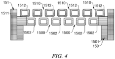
- FIG. 4 is a cross-sectional view of an air outlet face structure according to some embodiments of the present application.
- the first tuyeres 110 and the second tuyeres 120 each comprise an air outlet face structure 15, and the air outlet face structure 15 comprises a boosting part 150 and an air outlet part 151 which are superposed in an air outlet direction with a gap therebetween; and the boosting part 150 is formed with a plurality of first slits 1500 at intervals, and the air outlet part 151 is formed with a plurality of second slits 1510, the first slits 1500 being staggered with the second slits 1510.
- the air outlet face structure 15 refers to a structure for blowing out an airflow, and the air outlet face structure 15 faces the electrode plate, such that the airflow flows to the electrode plate to dry the electrode plate.
- the boosting part 150 is a part arranged on a side of the air outlet part 151 away from the electrode plate.
- the first slits 1500 on the boosting part 150 allow the airflow to pass through, so as to increase the pressure of the airflow and make the airflow flow to the second slits 1510.
- the air outlet part 151 is a part facing the electrode plate, and the airflow is blown out from the second slits 1510 to act on the electrode plate.
- the sum of the air outlet areas of the second slits 1510 on the air outlet part 151 is equal to the air outlet area of the tuyeres (the first tuyeres 110 or the second tuyeres 120).
- the cross-sectional area of the second slits 1510 of the first tuyeres 110 may be smaller than the cross-sectional area of the second slits 1510 of the second tuyeres 120, such that the air outlet area of the first tuyeres 110 is smaller than that of the second tuyeres 120, and thus the air outlet speed of the first oven section 11 is greater than that of the second oven section 12.
- the number of the second slits 1510 of the first tuyeres 110 can be less than the number of the second slits 1510 of the second tuyeres 120, such that the air outlet area of the first tuyeres 110 is smaller than the air outlet area of the second tuyeres 120, and thus the air outlet speed of the first oven section 11 is greater than that of the second oven section 12.
- the first tuyeres 110 and the second tuyeres 120 each comprise an air outlet face structure 15, and the air outlet face structure 15 has the advantages of a simple structure and being easy to manufacture, which can effectively reduce the manufacturing cost of the drying device 10.
- the airflow passes through the first slits 1500, the gap between the boosting part 150 and the air outlet part 151, and is ejected from the second slits 1510, which can improve the uniformity of the air outlet of the tuyeres, prevent damages to the film layer of the electrode plate due to turbulences, and ensure the drying effect of the material.
- the structure of the third tuyeres 130 may be identical to that of tuyeres in an existing drying device or an existing oven.
- the boosting part 150 comprises a first frame 1501 and a plurality of first connecting portions 1502 arranged in the first frame 1501, each of the first connecting portions 1502 is connected to the first frame 1501 at two ends, and the first slits 1500 are formed between two adjacent ones of the first connecting portions 1502; and the air outlet part 151 comprises a second frame 1511 and a plurality of second connecting portions 1512 arranged in the second frame 1511, each of the second connecting portions 1512 is connected to the second frame 1511 at two ends, and the second slits 1510 are formed between two adjacent ones of the second connecting portions 1512.
- the first frame 1501 comprises a plurality of walls which are sequentially connected to have a form of a frame.
- the first connecting portions 1502 are parts disposed in the first frame 1501, the first connecting portions 1502 are connected to an inner wall of the first frame 1501, and a plurality of first connecting portions 1502 are arranged at intervals to form the plurality of first slits 1500.
- the second frame 1511 comprises a plurality of walls enclosing a frame.
- the second connecting portions 1512 are parts disposed in the second frame 1511, the second connecting portions 1512 are connected to an inner wall of the second frame 1511, and the plurality of second connecting portions 1512 are arranged at intervals to form the plurality of second slits 1510.
- the first connecting portions 1502 are located at one end of the first frame 1501, a chamber is formed between the first connecting portions 1502 and the other end of the first frame 1501, and the size of the second frame 1511 is smaller than that of the first frame 1501, such that the second frame 1511 can be placed in the chamber and a lateral wall of a wall of the second frame 1511 is in contact with the inner wall of the first frame 1501, and an end surface of the wall of the second frame 1511 facing the first connecting portions 1502 abuts against the first connecting portions 1502.
- the second connecting portions 1512 are disposed in the second frame 1511, and have a certain distance from the end surface of the second frame 1511 facing the first connecting portions 1502, such that when the second frame 1511 is placed in the first frame 1501, a gap is formed between the first connecting portions 1502 and the second connecting portions 1512 for an airflow to pass through.
- the boosting part 150 has a simple structure and is easy to manufacture, and the plurality of first connecting portions 1502 are arranged at intervals in the first frame 1501 to form the first slits 1500, which effectively reduces the manufacturing difficulty of the boosting part 150.
- the air outlet part 151 has a simple structure and is easy to manufacture.
- the plurality of second connecting portions 1512 are arranged at intervals in the second frame 1511 to directly form the second slits 1510, which can effectively reduce the manufacturing difficulty of the boosting part 150.
- the air outlet area of the air outlet part 151 accounts for 10-20% of the total area of the air outlet part 151, the widths of the first slits 1500 and the second slits 1510 are between 2-8 mm, the number of the first slits 1500 and the number of the second slits 1510 are between 4-12 respectively, and the total air outlet area of the air outlet part 151 is not less than 17,000 mm 2 .
- the air outlet area of the air outlet part 151 accounts for 20-40% of the total area of the air outlet part 151, the widths of the first slits 1500 and the second slits 1510 are between 2-8 mm, the numbers of the first slit 1500 and the number of the second slits 1510 are between 6-18 respectively, the total air outlet area of the air outlet part 151 is not less than 25,000 mm 2 , and the gap between the boosting part 150 and the air outlet part 151 is between 2-5 mm.
- the cross sections of the first connecting portions 1502 and the second connecting portions 1512 may be square, such that the first slits 1500 and the second slits 1510 are strip-shaped, so as to ensure the uniformity of air outlet.
- first connecting portions 1502 and/or the second connecting portions 1512 are hollow structures.
- a hollow structure refers to a component having a cavity therein.
- the interior of the hollow structure is configured as a cavity to enable to effectively reduce the mass and used materials of the component.
- the first connecting portions 1502 and/or the second connecting portions 1512 being hollow structures means that the first connecting portions 1502 are hollow structure, the second connecting portions 1512 are hollow structures, or both the first connecting portions 1502 and the second connecting portions 1512 are hollow structures.
- the first connecting portions 1502 and/or the second connecting portions 1512 are configured as hollow structures, such that the mass of the first tuyeres 110 and the second tuyeres 120 can be effectively reduced, and the material cost of the first tuyeres 110 and the second tuyeres 120 can be saved.
- first connecting portions 1502 and/or the second connecting portions 1512 may be rectangular tubes (square tubes) of materials which are not limited, such as stainless steel rectangular tubes, aluminum alloy rectangular tubes, or plastic rectangular tubes, etc.
- the materials of the first frame 1501 and the second frame 1511 are not limited, and the first frame and the second frame may be made of steel, an aluminum alloy, or plastics.
- Some embodiments of the present application further provide an electrode plate manufacturing apparatus, comprising a coating device and the drying device 10 as described above, the coating device being configured for coating a slurry on a surface of an electrode plate.
- the drying device 10 is disposed downstream of the coating device for drying the slurry on the electrode plate.
- the coating device is an apparatus that can evenly coat the slurry (an active material) on a current collector, i.e., the electrode plate.
- the drying device 10 is an apparatus that can quickly dry the slurry on the electrode plate.
- the drying device 10 described above can increase the drying efficiency of the electrode plate while ensuring the drying quality of the electrode plate, thereby increasing the production efficiency of a battery.
- the drying device 10 comprises a first oven section 11, a second oven section 12 and a third oven section 13.
- the first oven section 11, the second oven section 12 and the third oven section 13 are arranged sequentially in a movement direction of an electrode plate.
- the first oven section 11, the second oven section 12 and the third oven section 13 are supplied with air from the same air source.
- the second oven section 12 has a larger air outlet area than the first oven section 11, and the first oven section 11 has a larger air outlet area than the third oven section 13, such that the air speed of the first oven section 11 is greater than that of the second oven section 12, and the air speed of the third oven section 13 is greater than that of the first oven section 11.
- the first oven section 11 has an air speed of less than 15 m/s
- the second oven section 12 has an air speed of less than 10 m/s
- the third oven section 13 has an air speed of 15-30 m/s.
- the first oven section 11 is provided with at least 15 first tuyeres 110 per 5 m, such that the air outlet area of the first oven section 11 is not less than 255,000 mm 2 /5 m;
- the second oven section 12 is provided with at least 15 second tuyeres 120 per 5 m, such that the air outlet area of the second oven section 12 is not less than 375,000 mm 2 /5 m;
- the third oven section 13 is provided with at least 15 third tuyeres 130 per 5 m, such that the air outlet area of the third oven section 13 is not less than 84,000 mm 2 /5 m.
- the center-to-center distance between two adjacent tuyeres is not greater than 0.3 mm (that is, the minimum distance between adjacent first tuyeres is 0.3 mm, and the minimum distance between adjacent second tuyeres 0.3 mm, and the minimum distance between adjacent third tuyeres is 0.3 mm).
- the volume of air of the first oven section 11 accounts for 30-60% of the total volume of air of the drying device 10
- the volume of air of the second oven section 12 accounts for 15-35% of the total volume of air of the drying device
- the volume of air of the third oven section 13 accounts for 20-40% of the total volume of air of the drying device 10.
- the first tuyeres 110 and the second tuyeres 120 each comprises an air outlet face structure 15, and the air outlet surface structure 15 comprises a boosting part 150 and an air outlet part 151.
- the boosting part comprises a first frame 1501 of steel and a plurality of first connecting portions 1502, the first connecting portions 1502 being stainless steel rectangular tubes.
- the plurality of first connecting portions 1502 are arranged at intervals in the first frame 1501 to form a plurality of first slits 1500.
- the air outlet part 151 comprises a second frame 1511 of steel and a plurality of second connecting portions 1512, the second connecting portions 1512 being stainless steel rectangular tubes.
- the plurality of second connecting portions 1512 are arranged at intervals in the second frame 1511 to form a plurality of second slits 1510.
- the air outlet part 151 is placed in the first frame 1501 such that the first connecting portions 1502 and the second connecting portions 1512 are spaced apart from each other, and the first slits 1500 are staggered with the second slits 1510.
- the airflow in the oven passes through the first slits 1500 of the boosting part 150, then passes through the second slits 1510 of the air outlet part 151, and finally is blown to the electrode plate.
- the air outlet area of the air outlet part 151 accounts for 10-20% of the total area of the air outlet part 151, and the widths of the first slits 1500 and the second slits 1510 are between 2-8mm, the number of the first slits 1500 and the number of the second slits 1510 are between 4-12 respectively, and the total air outlet area of the air outlet part 151 is not less than 17,000 mm 2 .
- the air outlet area of the air outlet part 151 accounts for 20-40% of the total area of the air outlet part 151, the widths of the first slits 1500 and the second slits 1510 are between 2-8 mm, the numbers of the first slit 1500 and the number of the second slits 1510 are between 6-18 respectively, the total air outlet area of the air outlet part 151 is not less than 25,000 mm 2 , and the gap between the boosting part 150 and the air outlet part 151 is between 2-5 mm.
- this embodiment provides Table 1 to clearly illustrate the data of various factors in the oven device.
- volume of air air speed * total air outlet area of a single oven section * number of ovens sections/1000000 * 3600.
- the distribution ratio of the volume of air may range from: 30-60% for the first oven section 11, 15-35% for the second oven section 12 and 20-40% for the third oven section 13.
- the number of the tuyeres of each oven section is 15, and the total volume of air of the oven device is 61689.6m 2 /h.
- Table 1 Oven sections Air speed range (m/s) Actual value of air speed Air outlet area of single tuyere (mm 2 ) Air outlet area of single oven section (5 m) (mm 2 ) Number of oven sections (quantity) Total volume of air of each oven section Distribution ratio of volume of air First oven section Less than 15 10 16800 252000 3 27216 44.1% Second oven section Less than 10 4 25200 378000 3 16329.6 26.5% Second oven section 10-30 20 5600 84000 3 18144 29.4%
Landscapes
- Engineering & Computer Science (AREA)
- Mechanical Engineering (AREA)
- General Engineering & Computer Science (AREA)
- Life Sciences & Earth Sciences (AREA)
- Microbiology (AREA)
- Battery Electrode And Active Subsutance (AREA)
- Drying Of Solid Materials (AREA)
Applications Claiming Priority (1)
| Application Number | Priority Date | Filing Date | Title |
|---|---|---|---|
| CN202220209736.XU CN217094252U (zh) | 2022-01-25 | 2022-01-25 | 烘干装置和极片制造设备 |
Publications (3)
| Publication Number | Publication Date |
|---|---|
| EP4227621A1 true EP4227621A1 (de) | 2023-08-16 |
| EP4227621C0 EP4227621C0 (de) | 2024-11-06 |
| EP4227621B1 EP4227621B1 (de) | 2024-11-06 |
Family
ID=82596723
Family Applications (1)
| Application Number | Title | Priority Date | Filing Date |
|---|---|---|---|
| EP23151864.8A Active EP4227621B1 (de) | 2022-01-25 | 2023-01-17 | Trocknungsvorrichtung und elektrodenplattenherstellungsvorrichtung |
Country Status (3)
| Country | Link |
|---|---|
| US (1) | US12516882B2 (de) |
| EP (1) | EP4227621B1 (de) |
| CN (1) | CN217094252U (de) |
Families Citing this family (4)
| Publication number | Priority date | Publication date | Assignee | Title |
|---|---|---|---|---|
| WO2024044902A1 (zh) * | 2022-08-29 | 2024-03-07 | 宁德时代新能源科技股份有限公司 | 烘干装置和极片制造设备 |
| DE102024122918A1 (de) * | 2024-08-12 | 2026-02-12 | Bayerische Motoren Werke Aktiengesellschaft | Verfahren und Vorrichtung zur Trocknung von Elektrodenbeschichtungen |
| CN119189157B (zh) * | 2024-10-17 | 2025-03-11 | 广东程森机械设备有限公司 | 一种双向拉伸塑料薄膜生产用模块式烘箱 |
| CN119725396A (zh) * | 2024-12-17 | 2025-03-28 | 惠州亿纬锂能股份有限公司 | 一种极片的制备方法、储能电池 |
Citations (3)
| Publication number | Priority date | Publication date | Assignee | Title |
|---|---|---|---|---|
| CN102423749A (zh) * | 2011-12-27 | 2012-04-25 | 深圳市赢合科技股份有限公司 | 一种极片涂布机的极片烘干系统 |
| CN103779538A (zh) * | 2012-10-19 | 2014-05-07 | 丰田自动车株式会社 | 用于二次电池电极的制造方法和电极制造装置 |
| CN108906536A (zh) * | 2018-07-19 | 2018-11-30 | 深圳市赢合科技股份有限公司 | 一种锂电池涂布机干燥系统 |
Family Cites Families (4)
| Publication number | Priority date | Publication date | Assignee | Title |
|---|---|---|---|---|
| JP5655769B2 (ja) * | 2011-12-09 | 2015-01-21 | トヨタ自動車株式会社 | 電極の製造方法 |
| CN202427624U (zh) | 2011-12-27 | 2012-09-12 | 深圳市赢合科技股份有限公司 | 一种极片涂布机的极片烘干系统 |
| JP2020001383A (ja) * | 2018-06-22 | 2020-01-09 | 住友化学株式会社 | 樹脂フィルムの製造方法 |
| EP4109580B1 (de) * | 2020-11-18 | 2025-06-11 | LG Energy Solution, Ltd. | Automatisches elektrodentrocknungssteuerungssystem und automatisches elektrodentrocknungssteuerungsverfahren |
-
2022
- 2022-01-25 CN CN202220209736.XU patent/CN217094252U/zh active Active
-
2023
- 2023-01-17 EP EP23151864.8A patent/EP4227621B1/de active Active
- 2023-01-18 US US18/098,246 patent/US12516882B2/en active Active
Patent Citations (3)
| Publication number | Priority date | Publication date | Assignee | Title |
|---|---|---|---|---|
| CN102423749A (zh) * | 2011-12-27 | 2012-04-25 | 深圳市赢合科技股份有限公司 | 一种极片涂布机的极片烘干系统 |
| CN103779538A (zh) * | 2012-10-19 | 2014-05-07 | 丰田自动车株式会社 | 用于二次电池电极的制造方法和电极制造装置 |
| CN108906536A (zh) * | 2018-07-19 | 2018-11-30 | 深圳市赢合科技股份有限公司 | 一种锂电池涂布机干燥系统 |
Also Published As
| Publication number | Publication date |
|---|---|
| US20230235957A1 (en) | 2023-07-27 |
| EP4227621C0 (de) | 2024-11-06 |
| US12516882B2 (en) | 2026-01-06 |
| CN217094252U (zh) | 2022-08-02 |
| EP4227621B1 (de) | 2024-11-06 |
Similar Documents
| Publication | Publication Date | Title |
|---|---|---|
| EP4227621A1 (de) | Trocknungsvorrichtung und elektrodenplattenherstellungsvorrichtung | |
| EP4357031B1 (de) | Ofen und produktionsausrüstung für batteriemontagestrasse | |
| KR101141792B1 (ko) | 전지용 극판의 제조방법 | |
| US20230304736A1 (en) | Air outlet apparatus and drying device | |
| US20240238827A1 (en) | Coating die and battery electrode plate coating apparatus | |
| US20150372286A1 (en) | Apparatus for material spray deposition of high solid percentage slurries for battery active material manufacture applications | |
| WO2023246220A1 (zh) | 极片烘干装置、电池生产设备及极片烘干方法 | |
| EP4322241A1 (de) | Elektrodenplattenerweiterungsvorrichtung und elektrodenplattenherstellungsvorrichtung | |
| KR20170024669A (ko) | 전극 합제 양면 분사 방식의 전극 시트 제조장치 | |
| EP4106039B1 (de) | Elektrodensubstrattrocknungsausrüstung mit einem sieb zur strömungsverteilung und verfahren dafür | |
| CN110404730B (zh) | 一种挤压垫片、涂布机及极片涂布工艺 | |
| US12015138B2 (en) | Strip diverting mechanism, drying device and electrode plate manufacturing apparatus | |
| CN221051971U (zh) | 镀膜设备 | |
| US20260118059A1 (en) | Oven drying apparatus and electrode plate manufacturing device | |
| JPH11329416A (ja) | シート電極の製造方法 | |
| US20230417483A1 (en) | Electrode sheet oven drying apparatus, battery production device, and electrode sheet oven drying method | |
| WO2025018644A1 (ko) | 슬롯 다이 코터 및 이를 이용한 이차전지용 전극판 제조 방법 | |
| CN215390536U (zh) | 一种锂离子电池极片烘干装置及涂布机 | |
| KR100709228B1 (ko) | 슬러리 도포설비의 코터기 | |
| CN211088395U (zh) | 一种放电效率高的锂一次电池 | |
| CN219051901U (zh) | 浆料涂布设备以及电池加工系统 | |
| KR20150131562A (ko) | 전극판 건조 장치 | |
| CN219923560U (zh) | 一种防止卷边的锂电池涂布烘箱 | |
| CN221747257U (zh) | 极片、电池及电子装置 | |
| US20250144644A1 (en) | Gas injection nozzle for drying electrode plate and drying apparatus for electrode plate including the same |
Legal Events
| Date | Code | Title | Description |
|---|---|---|---|
| PUAI | Public reference made under article 153(3) epc to a published international application that has entered the european phase |
Free format text: ORIGINAL CODE: 0009012 |
|
| STAA | Information on the status of an ep patent application or granted ep patent |
Free format text: STATUS: REQUEST FOR EXAMINATION WAS MADE |
|
| 17P | Request for examination filed |
Effective date: 20230117 |
|
| AK | Designated contracting states |
Kind code of ref document: A1 Designated state(s): AL AT BE BG CH CY CZ DE DK EE ES FI FR GB GR HR HU IE IS IT LI LT LU LV MC ME MK MT NL NO PL PT RO RS SE SI SK SM TR |
|
| STAA | Information on the status of an ep patent application or granted ep patent |
Free format text: STATUS: EXAMINATION IS IN PROGRESS |
|
| 17Q | First examination report despatched |
Effective date: 20240307 |
|
| GRAP | Despatch of communication of intention to grant a patent |
Free format text: ORIGINAL CODE: EPIDOSNIGR1 |
|
| STAA | Information on the status of an ep patent application or granted ep patent |
Free format text: STATUS: GRANT OF PATENT IS INTENDED |
|
| INTG | Intention to grant announced |
Effective date: 20240819 |
|
| GRAS | Grant fee paid |
Free format text: ORIGINAL CODE: EPIDOSNIGR3 |
|
| RAP1 | Party data changed (applicant data changed or rights of an application transferred) |
Owner name: CONTEMPORARY AMPEREX TECHNOLOGY(HONG KONG) LIMITED |
|
| GRAA | (expected) grant |
Free format text: ORIGINAL CODE: 0009210 |
|
| STAA | Information on the status of an ep patent application or granted ep patent |
Free format text: STATUS: THE PATENT HAS BEEN GRANTED |
|
| AK | Designated contracting states |
Kind code of ref document: B1 Designated state(s): AL AT BE BG CH CY CZ DE DK EE ES FI FR GB GR HR HU IE IS IT LI LT LU LV MC ME MK MT NL NO PL PT RO RS SE SI SK SM TR |
|
| REG | Reference to a national code |
Ref country code: GB Ref legal event code: FG4D |
|
| REG | Reference to a national code |
Ref country code: CH Ref legal event code: EP |
|
| REG | Reference to a national code |
Ref country code: DE Ref legal event code: R096 Ref document number: 602023000892 Country of ref document: DE |
|
| REG | Reference to a national code |
Ref country code: IE Ref legal event code: FG4D |
|
| U01 | Request for unitary effect filed |
Effective date: 20241129 |
|
| U07 | Unitary effect registered |
Designated state(s): AT BE BG DE DK EE FI FR IT LT LU LV MT NL PT RO SE SI Effective date: 20241211 |
|
| U20 | Renewal fee for the european patent with unitary effect paid |
Year of fee payment: 3 Effective date: 20250122 |
|
| PG25 | Lapsed in a contracting state [announced via postgrant information from national office to epo] |
Ref country code: HR Free format text: LAPSE BECAUSE OF FAILURE TO SUBMIT A TRANSLATION OF THE DESCRIPTION OR TO PAY THE FEE WITHIN THE PRESCRIBED TIME-LIMIT Effective date: 20241106 Ref country code: IS Free format text: LAPSE BECAUSE OF FAILURE TO SUBMIT A TRANSLATION OF THE DESCRIPTION OR TO PAY THE FEE WITHIN THE PRESCRIBED TIME-LIMIT Effective date: 20250306 |
|
| PG25 | Lapsed in a contracting state [announced via postgrant information from national office to epo] |
Ref country code: ES Free format text: LAPSE BECAUSE OF FAILURE TO SUBMIT A TRANSLATION OF THE DESCRIPTION OR TO PAY THE FEE WITHIN THE PRESCRIBED TIME-LIMIT Effective date: 20241106 |
|
| PG25 | Lapsed in a contracting state [announced via postgrant information from national office to epo] |
Ref country code: NO Free format text: LAPSE BECAUSE OF FAILURE TO SUBMIT A TRANSLATION OF THE DESCRIPTION OR TO PAY THE FEE WITHIN THE PRESCRIBED TIME-LIMIT Effective date: 20250206 |
|
| PG25 | Lapsed in a contracting state [announced via postgrant information from national office to epo] |
Ref country code: GR Free format text: LAPSE BECAUSE OF FAILURE TO SUBMIT A TRANSLATION OF THE DESCRIPTION OR TO PAY THE FEE WITHIN THE PRESCRIBED TIME-LIMIT Effective date: 20250207 |
|
| PG25 | Lapsed in a contracting state [announced via postgrant information from national office to epo] |
Ref country code: PL Free format text: LAPSE BECAUSE OF FAILURE TO SUBMIT A TRANSLATION OF THE DESCRIPTION OR TO PAY THE FEE WITHIN THE PRESCRIBED TIME-LIMIT Effective date: 20241106 |
|
| PG25 | Lapsed in a contracting state [announced via postgrant information from national office to epo] |
Ref country code: RS Free format text: LAPSE BECAUSE OF FAILURE TO SUBMIT A TRANSLATION OF THE DESCRIPTION OR TO PAY THE FEE WITHIN THE PRESCRIBED TIME-LIMIT Effective date: 20250206 |
|
| PG25 | Lapsed in a contracting state [announced via postgrant information from national office to epo] |
Ref country code: SM Free format text: LAPSE BECAUSE OF FAILURE TO SUBMIT A TRANSLATION OF THE DESCRIPTION OR TO PAY THE FEE WITHIN THE PRESCRIBED TIME-LIMIT Effective date: 20241106 |
|
| PG25 | Lapsed in a contracting state [announced via postgrant information from national office to epo] |
Ref country code: SK Free format text: LAPSE BECAUSE OF FAILURE TO SUBMIT A TRANSLATION OF THE DESCRIPTION OR TO PAY THE FEE WITHIN THE PRESCRIBED TIME-LIMIT Effective date: 20241106 |
|
| PG25 | Lapsed in a contracting state [announced via postgrant information from national office to epo] |
Ref country code: CZ Free format text: LAPSE BECAUSE OF FAILURE TO SUBMIT A TRANSLATION OF THE DESCRIPTION OR TO PAY THE FEE WITHIN THE PRESCRIBED TIME-LIMIT Effective date: 20241106 |
|
| PLBE | No opposition filed within time limit |
Free format text: ORIGINAL CODE: 0009261 |
|
| STAA | Information on the status of an ep patent application or granted ep patent |
Free format text: STATUS: NO OPPOSITION FILED WITHIN TIME LIMIT |
|
| PG25 | Lapsed in a contracting state [announced via postgrant information from national office to epo] |
Ref country code: MC Free format text: LAPSE BECAUSE OF FAILURE TO SUBMIT A TRANSLATION OF THE DESCRIPTION OR TO PAY THE FEE WITHIN THE PRESCRIBED TIME-LIMIT Effective date: 20241106 |
|
| 26N | No opposition filed |
Effective date: 20250807 |
|
| PG25 | Lapsed in a contracting state [announced via postgrant information from national office to epo] |
Ref country code: IE Free format text: LAPSE BECAUSE OF NON-PAYMENT OF DUE FEES Effective date: 20250117 |
|
| U20 | Renewal fee for the european patent with unitary effect paid |
Year of fee payment: 4 Effective date: 20260127 |