EP4227647B1 - Verfahren zur kalibrierung einer linearisierungsfunktion zur korrektur des ausgangs eines positionssensors - Google Patents
Verfahren zur kalibrierung einer linearisierungsfunktion zur korrektur des ausgangs eines positionssensors Download PDFInfo
- Publication number
- EP4227647B1 EP4227647B1 EP22155840.6A EP22155840A EP4227647B1 EP 4227647 B1 EP4227647 B1 EP 4227647B1 EP 22155840 A EP22155840 A EP 22155840A EP 4227647 B1 EP4227647 B1 EP 4227647B1
- Authority
- EP
- European Patent Office
- Prior art keywords
- linearization
- position sensor
- output
- signal
- initial
- Prior art date
- Legal status (The legal status is an assumption and is not a legal conclusion. Google has not performed a legal analysis and makes no representation as to the accuracy of the status listed.)
- Active
Links
Images


Classifications
-
- G—PHYSICS
- G01—MEASURING; TESTING
- G01D—MEASURING NOT SPECIALLY ADAPTED FOR A SPECIFIC VARIABLE; ARRANGEMENTS FOR MEASURING TWO OR MORE VARIABLES NOT COVERED IN A SINGLE OTHER SUBCLASS; TARIFF METERING APPARATUS; MEASURING OR TESTING NOT OTHERWISE PROVIDED FOR
- G01D18/00—Testing or calibrating apparatus or arrangements provided for in groups G01D1/00 - G01D15/00
- G01D18/001—Calibrating encoders
-
- G—PHYSICS
- G01—MEASURING; TESTING
- G01D—MEASURING NOT SPECIALLY ADAPTED FOR A SPECIFIC VARIABLE; ARRANGEMENTS FOR MEASURING TWO OR MORE VARIABLES NOT COVERED IN A SINGLE OTHER SUBCLASS; TARIFF METERING APPARATUS; MEASURING OR TESTING NOT OTHERWISE PROVIDED FOR
- G01D18/00—Testing or calibrating apparatus or arrangements provided for in groups G01D1/00 - G01D15/00
- G01D18/008—Testing or calibrating apparatus or arrangements provided for in groups G01D1/00 - G01D15/00 with calibration coefficients stored in memory
-
- G—PHYSICS
- G01—MEASURING; TESTING
- G01D—MEASURING NOT SPECIALLY ADAPTED FOR A SPECIFIC VARIABLE; ARRANGEMENTS FOR MEASURING TWO OR MORE VARIABLES NOT COVERED IN A SINGLE OTHER SUBCLASS; TARIFF METERING APPARATUS; MEASURING OR TESTING NOT OTHERWISE PROVIDED FOR
- G01D5/00—Mechanical means for transferring the output of a sensing member; Means for converting the output of a sensing member to another variable where the form or nature of the sensing member does not constrain the means for converting; Transducers not specially adapted for a specific variable
- G01D5/12—Mechanical means for transferring the output of a sensing member; Means for converting the output of a sensing member to another variable where the form or nature of the sensing member does not constrain the means for converting; Transducers not specially adapted for a specific variable using electric or magnetic means
- G01D5/14—Mechanical means for transferring the output of a sensing member; Means for converting the output of a sensing member to another variable where the form or nature of the sensing member does not constrain the means for converting; Transducers not specially adapted for a specific variable using electric or magnetic means influencing the magnitude of a current or voltage
- G01D5/20—Mechanical means for transferring the output of a sensing member; Means for converting the output of a sensing member to another variable where the form or nature of the sensing member does not constrain the means for converting; Transducers not specially adapted for a specific variable using electric or magnetic means influencing the magnitude of a current or voltage by varying inductance, e.g. by a movable armature
- G01D5/204—Mechanical means for transferring the output of a sensing member; Means for converting the output of a sensing member to another variable where the form or nature of the sensing member does not constrain the means for converting; Transducers not specially adapted for a specific variable using electric or magnetic means influencing the magnitude of a current or voltage by varying inductance, e.g. by a movable armature by influencing the mutual induction between two or more coils
- G01D5/2053—Mechanical means for transferring the output of a sensing member; Means for converting the output of a sensing member to another variable where the form or nature of the sensing member does not constrain the means for converting; Transducers not specially adapted for a specific variable using electric or magnetic means influencing the magnitude of a current or voltage by varying inductance, e.g. by a movable armature by influencing the mutual induction between two or more coils by a movable non-ferromagnetic conductive element
Definitions
- the invention relates to a method for calibrating a linearization function for correcting the output of a position sensor providing a continuous output position signal.
- the invention further relates to a position sensor implementing the method according to the present invention.
- Inductive position sensors implement a magnet-free technology, utilizing the physical principles of eddy currents or inductive coupling to detect the position of a target that is moving above a set of coils, consisting for example of one transmitter coil and two receiver coils, particularly a sine receiver coil and a cosine receiver coil.
- a set of coils consisting for example of one transmitter coil and two receiver coils, particularly a sine receiver coil and a cosine receiver coil.
- Such an inductive sensor system is for example disclosed in Patent Document 1.
- the electromagnetic field generated by the transmitter, and the resulting fields generated in the metallic target may be non-uniform
- the connections of wire traces to the transmitter coil and the arrangement of receiver coils, particularly the sine receiver coil and the cosine receiver coil may result in further non-uniformity.
- the air gap between the metallic target and the coils mounted on the Printed Circuit Board (PCB) may be non-uniform.
- the amplitudes of signals generated by the receiver coils may have an offset. There may be mismatches between the multiple receiver coils. There may be different coupling effects between the metallic target and each of the multiple receiver coils. These and other factors may result in inaccurate results of the position locating system.
- Patent Document 2 discloses a method of calibrating and linearization. According to this method, spatial angle data is read from the position sensor at a set of positions of a target swept over receive coils in the position sensor. From the spatial angle data, calibration parameters are calculated by matching an electrical measured position with a mechanical reference position. Afterwards initial position values are determined from the spatial angle data and the calibration parameters. The initial position values are used to determine linearization parameters by linearization of the measured position. The calibration parameters and linearization parameters are written into the position sensor.
- the object is solved by a method for calibrating a linearization function for correcting the output of a position sensor providing a continuous output position signal, wherein the linearization function has a predetermined number of linearization points, wherein each linearization point specifies a correction factor for a corresponding position of the output signal of the position sensor, comprising the steps of:
- the linearization function specifies correction factors for certain positions of the output of the position sensor.
- the correction factor corresponds to the difference of the position information of the position sensor and the position information of the reference signal at a certain position.
- the corresponding correction factor is obtained from interpolation between the adjacent linearization points.
- the initial positions for all available linearization points i.e. the predetermined number of linearization points.
- the correction factors for these initial positions of the linearization functions are zero at this stage of the method because the difference of the output of the position sensor to an ideal position signal is unknown.
- the output of the position sensor is determined for a full period by applying the linearization function to the position signal of the position sensor for the full period.
- the error of the output of the position sensor is not corrected, since the correction factors of all linearization points is zero.
- This step could also be referred to as determining the uncorrected output of the position sensor without applying the linearization function.
- the same algorithm is used as during the correction of the position signal of the position sensor using a linearization function with correction factors being zero.
- the correction factors of all initial linearization points are defined by comparing the output of the position sensor with a reference signal.
- the reference signal provides an ideal position signal for the full period of the position sensor, e.g. using ideal input signals or a high-precision position sensor, for example from a laboratory set-up.
- the corresponding correction factors for all linearization points can be defined.
- the correction factors correspond to the difference between the output of the position sensor and the reference signal at the position of the respective linearization point.
- the output of the position sensor is re-determined for a full period by applying the linearization function to the position signal of the position sensor for the full period.
- the output of the position sensor is corrected using the correction factors of the linearization function for the respective positions of the linearization points.
- the corresponding correction factor is obtained from interpolation between the adjacent linearization points.
- an error vector for the full period of the position sensor can be calculated by comparing the output of the position sensor with the reference signal.
- the error vector can also be referred to as error curve.
- the reference position can be determined using a certain sampling frequency, wherein the sampling frequency is much higher than the number of linearization points of the linearization function.
- the error vector is used to detect the maximum error of the output of the position sensor. This maximum error is checked against a predefined threshold, i.e. error level. If the maximum error is below the predefined threshold, the linearization function can be used to reduce the error of the output of the position sensor and is therefore stored in the position sensor.
- the linearization function is further optimized by amending the linearization point closest to the maximum error.
- the position of the maximum error is extracted from the error vector. Afterwards, the linearization point closest to the maximum error of the error vector is identified.
- the identified linearization point closest to the maximum error is modified by stepwise changing the position of the linearization point within predefined boundaries.
- the corresponding correction value of the linearization point is changed based on the comparison of the output of the position sensor with the reference signal.
- the optimization of the linearization function is terminated by setting the identified linearization point closest to the maximum error to the position of the found minimum error for that linearization point.
- Each linearization point corresponds to a position of the position sensor and a correction factor at this position determined based on the difference of the output of the position sensor at this position and the ideal position defined by the reference signal at that position.
- the linearization function is stored in the position sensor, for example in a register of a signal processing unit of the position sensor.
- the linearization function is used to correct the output of the position sensor and to fulfil certain requirements like Automotive Safety Integrity Levels (ASIL), e.g. required by autonomous driving systems.
- ASIL Automotive Safety Integrity Levels
- the linearization function comprises for example at least 16 linearization points. To improve the accuracy of the position sensor the number of linearization points can be increased. However, the processing power and storage of position sensors is limited, which restricts the number of linearization points of the linearization function.
- the method comprises the step of applying a zero calibration to the position sensor signal setting a mechanical initial position of the position sensor to a position value of zero.
- the start position of the position sensor is zero, like e.g. 0° for a rotational sensor.
- the method further comprises the step of applying a zero calibration to the reference signal setting a mechanical initial position of the reference signal to a position value of zero.
- a zero calibration to the reference signal setting a mechanical initial position of the reference signal to a position value of zero.
- the reference signal is provided by an external high precision position sensor system.
- the reference signal is generated by using an ideal input signal for calculating the position and the corresponding ideal output of the position sensor.
- the steps of re-determining the output of the position sensor, calculating the error vector, detecting the maximum error, and optimizing the linearization function are repeated until the maximum error is below the predefined threshold and/or until all initial linearization points of the linearization function have been optimized.
- more than one initial linearization point is optimized, particularly to guarantee a certain error level or to minimize the error as much as possible.
- the initially defined linearization point can be optimized sequentially until the maximum error is below the predefined threshold and/or until all initially defined linearization points have been optimized.
- the step of optimizing of the linearization function is only performed once for each initial linearization point.
- an initial linearization point i.e. the position and the correction values have been re-defined, it is afterwards not again optimized.
- the method comprises during each repetition the step of revising the correction factors corresponding to the difference between the output of the position sensor and the ideal position of the reference signal for all linearization points after the position of an initial linearization point has been amended.
- the setting of the initial positions for all available linearization points depends on the form of the expected output signal of the position sensor.
- the distance between two adjacent initial linearization points is constant for a linearly changing output signal.
- the number of initial linearization points is higher in areas of the output signal with a non-linearly rate of changing and lower in areas of the output signal with a constant output signal or a linearly changing output signal.
- the output of the position sensor can be for example a linear output with a positive or negative slope. In that case the initial linearization points are preferably equally spaced along the position of the position sensor.
- the initial linearization points may be positioned less frequently in the clamps area and more frequently in the slope area.
- Other possible output signals of the position sensor are for example double ramp output, trapezoid output, linear output with one or more breaks, and so on.
- the step size of the stepwise changing of the position of the linearization point within predefined boundaries depends on the position sensor, particularly on the resolution of the position sensor, the accuracy of the position sensor, the processing and/or storage capabilities of the position sensor or similar attributes of the position sensor. The higher the resolution and/or accuracy of the position sensor, the smaller should be the step size, to guarantee the resolution and/or accuracy.
- the step size further depends on the processing and/or storage capabilities of the position sensor because a smaller step size involves more computations and hence storage space.
- the boundaries of the stepwise changing of the position of the linearization point within predefined boundaries depend on the distance to the neighbouring linearization points.
- the boundaries should not exceed the distance to the neighbouring linearization point, to prevent a change of order of linearization points.
- Such a re-ordering can be avoided if the boundaries around the position of the initial linearization point are smaller than the distance to the neighbouring linearization points, particularly half or less than the distance to the neighbouring linearization points. Even if two neighbouring linearization points are optimized within the maximum possible boundaries, a re-ordering is avoided because the boundaries correspond to half the distance between two neighbouring linearization points.
- the original order of the linearization points is not changed by the method according to the invention. This simplifies the linearization function, as the processing unit of the position sensor can easily calculate the slope between each two linearization points of the linearization function, which is required to apply the linearization function to the continuous output signal of the position sensor.
- the object is further solved by a position sensor comprising a signal processing unit implementing the method according to the present invention.
- the position sensor particularly comprises a non-volatile storage for storing the linearization function determined by the inventive method.
- the stored linearization function can afterwards be applied to the output of the position sensor.
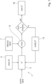
- the invention generally refers to a method 1 for calibrating a linearization function 2 for correcting the output of a position sensor providing a continuous output position signal, wherein the method 1 optimizes the linearization function 2 by defining optimal positions of the linearization points of the linearization function 2.
- Fig. 1 shows a flow diagram showing a generic overview of the method 1 according to the invention.
- the method 1 is intended for calibration of a linearization function 2 for correcting the output of a position sensor.
- the position sensor provides a continuous output signal.
- the linearization function 2 has a predetermined number of linearization points, wherein each linearization point specifies a correction factor for a corresponding position of the output signal of the position sensor.
- each linearization point comprises two values, one value specifying the position and one value specifying the correction value at this position.
- the linearization function 2 is initialized 3 by setting initial positions for all available linearization points.
- the correction factor of each initial linearization point is zero.
- the setting 3 of the initial positions for all available linearization points depends on the form of the expected output signal of the position sensor. For example, the distance between two adjacent initial linearization points is constant for a linearly changing output signal. Thus, for a linear output with a negative slope or positive slope the initial linearization points are equally spaced from each other. If the output signal is changing non-linearly, the number of initial linearization points is higher in areas of the output signal with a non-linearly rate of changing and lower in areas of the output signal with a constant output signal or a linearly changing output signal.
- the output of the position sensor is determined 5 for a full period by applying the linearization function 2 to the position signal of the position sensor for the full period.
- the correction factor for each initial linearization point can be defined by comparing the output of the position sensor with a reference signal 7.
- the reference signal 7 provides an ideal position signal for the full period of the position sensor.
- the reference signal 7 is for example provided by an external high precision position sensor system or the reference signal 7 is generated by using an ideal input signal for calculating the position and the corresponding ideal output of the position sensor.
- the output of the position sensor is re-determined 8 for a full period by applying the linearization function 2 to the position signal of the position sensor for the full period.
- an error vector for the full period can be calculated 9 by comparing the output of the position sensor with the reference signal 7. Furthermore, the maximum error of the error vector is detected 10.
- the linearization function 2 can be used to correct the position signal of the position sensor and to guarantee a certain error level.
- the linearization function 2 is optimized by sequentially modifying 13 one or more linearization points of the linearization function 2.
- the optimization of the linearization function 2 will be explained in more detail with respect to the embodiments shown in Figs. 2 to 4 .
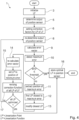
- Fig. 2 shows a flow diagram showing a detailed first embodiment of the method 1 according to the invention.
- the method 1 is used for calibrating a linearization function 2 to correct the output of a position sensor.
- the position sensor provides a continuous output signal.
- the linearization function 2 is initialized 3 by setting initial positions 4 for all available linearization points.
- the correction factor of each initial linearization point is zero.
- the output of the position sensor for a full period is determined 5 by applying the linearization function 2 to the position signal of the position sensor for the full period. Based on this, the correction factor of each initial linearization point can be set 6 by comparing the output of the position sensor with a reference signal 7, wherein the reference signal 7 provides an ideal position signal for the full period of the position sensor. Since the initial correction factor are zero, the linearization function 2 does not change the position signal of the position sensor. This step could also be referred to as determining the uncorrected output of the position sensor.
- the output of the position sensor is re-determined 8 for a full period by applying the linearization function 2 to the position signal of the position sensor for the full period.
- the positions of linearization points correspond to the positions defined during initializing 3 the linearization points and the correction factors correspond to the set 6 correction factors.
- an error vector is calculated 9 for the full period of the position sensor by comparing the output of the position sensor with the reference signal 7. Furthermore, the maximum error of the error vector will be detected 10.
- the linearization function 2 can be stored 16 in the position sensor and used for correction the position signal of the position sensor to provide a certain accuracy.
- the linearization function 2 is further optimized. Even if the maximum error is below the predefined threshold, the linearization function 2 can be further optimized to further improve the accuracy. In the latter case, the method 1 can buffer different linearization functions 2 and the corresponding maximum errors and decide at the end, which linearization function 2 has the lowest maximum error.
- the linearization function 2 is optimized by first extracting 11 the position of the maximum error from the error vector. In the following step, the linearization point closest to the maximum error of the error vector is identified 12.
- the linearization point that is closest to the maximum error is modified 13 by stepwise changing the position of the linearization point within predefined boundaries and changing the corresponding correction value based on the comparison of the output of the position sensor with the reference signal 7.
- the error vector is re-calculated 14, to find a position of a minimum error for that linearization point.
- the linearization point closest to the maximum error is set 15 to this position of the minimum error.
- the step size of the stepwise changing of the position of the linearization point within predefined boundaries depends on the position sensor, particularly on the resolution of the position sensor, the accuracy of the position sensor, the processing and/or storage capabilities of the position sensor or similar attributes of the position sensor.
- the boundaries of the stepwise changing of the position of the linearization point within predefined boundaries depend on the distance to the neighbouring linearization points.
- the boundaries around the position of the initial linearization point are smaller than the distance to the neighbouring linearization points, particularly half or less than the distance to the neighbouring linearization points.
- Fig. 3 shows a flow diagram showing a detailed second embodiment of the method 1 according to the invention.
- the second embodiment shown in Fig. 3 differs from the first embodiment shown in Fig. 2 in that the steps of re-determining 8 the output of the position sensor, calculating 9 the error vector, detecting 10 the maximum error and optimizing the linearization function 2 are repeated until the maximum error is below the predefined threshold and/or until all initial linearization points of the linearization function 2 have been optimized.
- each initial linearization point is only optimized once.
- Fig. 4 shows a flow diagram showing a detailed third embodiment of the method 1 according to the invention.
- the third embodiment shown in Fig. 4 differs from the second embodiment shown in Fig. 3 by revising 17 during each repetition the correction factors corresponding to the difference between the output of the position sensor and the ideal position of the reference signal 7 for all linearization points.
- the revising 17 is performed after the position of an initial linearization point has been amended, i.e. after one of the initial linearization points has been set 15 to a position corresponding to its minimum error.
Landscapes
- Physics & Mathematics (AREA)
- General Physics & Mathematics (AREA)
- Indication And Recording Devices For Special Purposes And Tariff Metering Devices (AREA)
Claims (15)
- Verfahren (1) zum Kalibrieren einer Linearisierungsfunktion (2) zum Korrigieren des Ausgangssignals eines Positionssensors, der ein kontinuierliches Ausgangspositionssignal liefert,wobei die Linearisierungsfunktion (2) eine vorbestimmte Anzahl von Linearisierungspunkten aufweist,wobei jeder Linearisierungspunkt einen Korrekturfaktor für eine entsprechende Position des Ausgangssignals des Positionssensors angibt, umfassend die Schritte:Initialisieren (3) der Linearisierungsfunktion (2) durch Festlegen von Anfangspositionen (4) für alle verfügbaren Linearisierungspunkte, wobei der Korrekturfaktor jedes anfänglichen Linearisierungspunktes Null ist;Bestimmen (5) des Ausgangssignals des Positionssensors für eine volle Periode durch Anwenden der Linearisierungsfunktion (2) auf das Positionssignal des Positionssensors für die volle Periode;Festlegen (6) des Korrekturfaktors für jeden anfänglichen Linearisierungspunkt durch Vergleichen des Ausgangssignals des Positionssensors mit einem Referenzsignal (7), wobei das Referenzsignal (7) ein ideales Positionssignal für die volle Periode des Positionssensors liefert;Neubestimmen (8) des Ausgangssignals des Positionssensors für eine volle Periode durch Anwenden der Linearisierungsfunktion (2) auf das Positionssignal des Positionssensors für die volle Periode;Berechnen (9) eines Fehlervektors für die volle Periode des Positionssensors durch Vergleichen des Ausgangssignals des Positionssensors mit dem Referenzsignal (7);Ermitteln (10) des maximalen Fehlers des Fehlervektors;wenn der maximale Fehler über einem vordefinierten Schwellenwert liegt, Optimieren der Linearisierungsfunktion (2) durch:Extrahieren (11) der Position des maximalen Fehlers aus dem Fehlervektor;Auffinden des Linearisierungspunkts (12), der dem maximalen Fehler des Fehlervektors am nächsten liegt;Modifizieren (13) des Linearisierungspunktes, der dem maximalen Fehler am nächsten liegt, durch schrittweises Ändern der Position des Linearisierungspunktes innerhalb vordefinierter Grenzen und Ändern des entsprechenden Korrekturwertes auf der Grundlage des Vergleichs des Ausgangssignals des Positionssensors mit dem Referenzsignal (7);Neuberechnen (14) des Fehlervektors für jeden Schritt des modifizierten Linearisierungspunktes, um eine Position eines minimalen Fehlers für diesen Linearisierungspunkt zu finden;Festlegen (15) des Linearisierungspunktes auf die Position des minimalen Fehlers;wenn der maximale Fehler unter dem vordefinierten Schwellenwert liegt:
Speichern (16) der Linearisierungsfunktion (2) im Positionssensor. - Das Verfahren (1) nach Anspruch 1,
umfassend den Schritt des Anwendens einer Nullkalibrierung auf das Positionssensorsignal, wobei eine mechanische Anfangsposition des Positionssensorsignals auf einen Positionswert von Null festgelegt wird. - Das Verfahren (1) nach Anspruch 2,
ferner umfassend den Schritt des Anwendens einer Nullkalibrierung auf das Referenzsignal (7), wobei eine mechanische Anfangsposition des Referenzsignals (7) auf einen Positionswert von Null festgelegt wird. - Das Verfahren (1) nach einem der Ansprüche 1 bis 3,
wobei das Referenzsignal (7) von einem externen hochpräzisen Positionssensorsystem bereitgestellt wird. - Das Verfahren (1) nach einem der Ansprüche 1 bis 3,
wobei das Referenzsignal (7) durch Verwenden eines idealen Eingangssignals zum Berechnen der Position und des entsprechenden idealen Ausgangssignals des Positionssensors erzeugt wird. - Das Verfahren (1) nach einem der Ansprüche 1 bis 5,
wobei die Schritte des Neubestimmens (8) des Ausgangssignals des Positionssensors, des Berechnens (9) des Fehlervektors, des Ermittelns (10) des maximalen Fehlers und des Optimierens (13, 14, 15) der Linearisierungsfunktion (2) wiederholt werden, bis der maximale Fehler unter dem vordefinierten Schwellenwert liegt und/oder bis alle anfänglichen Linearisierungspunkte der Linearisierungsfunktion (2) optimiert worden sind. - Das Verfahren (1) nach Anspruch 6,
wobei das Optimieren der Linearisierungsfunktion (2) nur einmal für jeden Anfangslinearisierungspunkt durchgeführt wird. - Das Verfahren (1) nach Anspruch 6 oder Anspruch 7, das bei jeder Wiederholung den Schritt des Überarbeitens (17) der Korrekturfaktoren umfasst, die der Differenz zwischen dem Ausgangssignal des Positionssensors und der idealen Position des Referenzsignals (7) für alle Linearisierungspunkte entsprechen, nachdem die Position eines anfänglichen Linearisierungspunktes geändert wurde.
- Das Verfahren (1) nach einem der Ansprüche 1 bis 8,
wobei das Festlegen (3) der Anfangspositionen für alle verfügbaren Linearisierungspunkte von der Form des erwarteten Ausgangssignals des Positionssensors abhängt. - Das Verfahren (1) nach Anspruch 9,
wobei der Abstand zwischen zwei benachbarten Anfangslinearisierungspunkten bei einem sich linear ändernden Ausgangssignal konstant ist. - Das Verfahren (1) nach Anspruch 9,
wobei die Anzahl der anfänglichen Linearisierungspunkte in Bereichen des Ausgangssignals mit einer nichtlinearen Änderungsrate höher und in Bereichen des Ausgangssignals mit einem konstanten Ausgangssignal oder einem sich linear ändernden Ausgangssignal niedriger ist. - Das Verfahren (1) nach einem der Ansprüche 1 bis 11,
wobei die Schrittweite des schrittweisen Veränderns der Position des Linearisierungspunktes innerhalb vorgegebener Grenzen von dem Positionssensor, insbesondere von der Auflösung des Positionssensors, der Genauigkeit des Positionssensors, den Verarbeitungs- und/oder Speichermöglichkeiten des Positionssensors oder ähnlichen Eigenschaften des Positionssensors abhängt. - Das Verfahren (1) nach einem der Ansprüche 1 bis 12,
wobei die Grenzen des schrittweisen Änderns der Position des Linearisierungspunktes innerhalb vorgegebener Grenzen von der Entfernung zu den benachbarten Linearisierungspunkten abhängen. - Das Verfahren (1) nach Anspruch 13,
wobei die Grenzen um die Position des anfänglichen Linearisierungspunktes kleiner sind als der Abstand zu den benachbarten Linearisierungspunkten, insbesondere die Hälfte oder weniger als der Abstand zu den benachbarten Linearisierungspunkten. - Positionssensor mit einer Signalverarbeitungseinheit, wobei die Signalverarbeitungseinheit zur Durchführung des Verfahrens (1) nach einem der Ansprüche 1 bis 14 eingerichtet ist.
Priority Applications (2)
| Application Number | Priority Date | Filing Date | Title |
|---|---|---|---|
| EP22155840.6A EP4227647B1 (de) | 2022-02-09 | 2022-02-09 | Verfahren zur kalibrierung einer linearisierungsfunktion zur korrektur des ausgangs eines positionssensors |
| US18/166,583 US12460952B2 (en) | 2022-02-09 | 2023-02-09 | Method for calibration linearization function for correcting output of position sensor |
Applications Claiming Priority (1)
| Application Number | Priority Date | Filing Date | Title |
|---|---|---|---|
| EP22155840.6A EP4227647B1 (de) | 2022-02-09 | 2022-02-09 | Verfahren zur kalibrierung einer linearisierungsfunktion zur korrektur des ausgangs eines positionssensors |
Publications (2)
| Publication Number | Publication Date |
|---|---|
| EP4227647A1 EP4227647A1 (de) | 2023-08-16 |
| EP4227647B1 true EP4227647B1 (de) | 2024-05-22 |
Family
ID=80446573
Family Applications (1)
| Application Number | Title | Priority Date | Filing Date |
|---|---|---|---|
| EP22155840.6A Active EP4227647B1 (de) | 2022-02-09 | 2022-02-09 | Verfahren zur kalibrierung einer linearisierungsfunktion zur korrektur des ausgangs eines positionssensors |
Country Status (2)
| Country | Link |
|---|---|
| US (1) | US12460952B2 (de) |
| EP (1) | EP4227647B1 (de) |
Family Cites Families (11)
| Publication number | Priority date | Publication date | Assignee | Title |
|---|---|---|---|---|
| IE55855B1 (en) | 1984-10-19 | 1991-01-30 | Kollmorgen Ireland Ltd | Position and speed sensors |
| US5396241A (en) * | 1993-02-03 | 1995-03-07 | Kaman Instrumentation Corporation | Method and apparatus for digitally controlled linearization of an analog signal |
| DE102016101965A1 (de) * | 2016-02-04 | 2017-08-10 | Fraba B.V. | Verfahren zum Kalibrieren eines Drehgebers und Drehgeber zur Bestimmung einer korrigierten Winkelposition |
| EP3232164B1 (de) * | 2016-04-13 | 2018-12-19 | ams AG | Positionssensor und verfahren zur erzeugung eines sensorausgangssignals |
| DE102016115624A1 (de) * | 2016-08-23 | 2018-03-01 | Fraba B.V. | Verfahren zum Kalibrieren eines Drehgebers und Drehgeber |
| US10659069B2 (en) * | 2018-02-02 | 2020-05-19 | Analog Devices, Inc. | Background calibration of non-linearity of samplers and amplifiers in ADCs |
| US11112274B2 (en) * | 2018-08-30 | 2021-09-07 | Integrated Device Technology, Inc. | Fully redundant position sensor |
| US11609082B2 (en) | 2018-09-21 | 2023-03-21 | Integrated Device Technology, Inc. | Calibration and linearization of position sensor |
| DE112019006140A5 (de) * | 2018-12-11 | 2021-10-14 | Chronos Vision Gmbh | Verfahren und Vorrichtung zur Positionsbestimmung mittels Trägheitsnavigation, und Kalibriersystem |
| US11099036B2 (en) * | 2019-07-10 | 2021-08-24 | Integrated Device Technology, Inc. | 360 degree position sensor |
| EP4227646B1 (de) * | 2022-02-09 | 2024-05-29 | Renesas Electronics America Inc. | Verfahren zur kalibrierung einer linearisierungsfunktion zur korrektur des ausgangs eines positionssensors |
-
2022
- 2022-02-09 EP EP22155840.6A patent/EP4227647B1/de active Active
-
2023
- 2023-02-09 US US18/166,583 patent/US12460952B2/en active Active
Also Published As
| Publication number | Publication date |
|---|---|
| US20230251115A1 (en) | 2023-08-10 |
| EP4227647A1 (de) | 2023-08-16 |
| US12460952B2 (en) | 2025-11-04 |
Similar Documents
| Publication | Publication Date | Title |
|---|---|---|
| US9255817B2 (en) | Rotation-angle detection device, image processing apparatus, and rotation-angle detection method | |
| EP2559971B1 (de) | Rotationswinkelerkennungsvorrichtung | |
| US9528815B2 (en) | Transformer based sensor arrangement | |
| US7496462B2 (en) | Encoding signal processing device and signal processing method therefor | |
| US6532791B2 (en) | Method for increasing the positioning accuracy of an element which is movably arranged relative to a stator | |
| CN111245306A (zh) | 信号处理装置以及信号处理方法 | |
| US10317249B2 (en) | Method for determining the position of a moving part along an axis, using an inductive sensor | |
| US20200378798A1 (en) | Angle sensor and method for operating an angle sensor | |
| US11536590B2 (en) | Offset correction device and position measuring device | |
| CN112584136B (zh) | 位置校准模块、校准方法、电子设备、校准装置及存储介质 | |
| US12460953B2 (en) | Method for calibrating linearization function for correcting output of position sensor | |
| EP4227647B1 (de) | Verfahren zur kalibrierung einer linearisierungsfunktion zur korrektur des ausgangs eines positionssensors | |
| CN101300461B (zh) | 线性和旋转mr阵列位置变换器微调补偿和皮重补偿的热系数 | |
| JPS62143120A (ja) | 座標入力装置 | |
| CN111256744B (zh) | 一种线性输出位置传感器标定方法 | |
| US11909282B2 (en) | Device, arrangement and method for determining an angle between a rotor and a stator | |
| US20080265807A1 (en) | Linear Motor and Transducer Arrangement Therefor | |
| WO2005071816A9 (en) | Linear motor and transducer arrangement therefor | |
| EP4571266A1 (de) | Selbstkorrigierender induktiver sensor | |
| US20250102329A1 (en) | Magnetic sensor system, and distance measuring method for the magnetic sensor system | |
| KR20250076268A (ko) | 이동 자석 선형 모터의 홀센서 오프셋 신호 보정 방법 및 장치 | |
| CN118464091A (zh) | 电感式角位置传感信号校正方法、系统及可读存储介质 | |
| CN116938060A (zh) | 无刷电机的电流和转子磁场角度偏差的校准系统及方法 | |
| JPH05297108A (ja) | 角度信号補正装置 |
Legal Events
| Date | Code | Title | Description |
|---|---|---|---|
| PUAI | Public reference made under article 153(3) epc to a published international application that has entered the european phase |
Free format text: ORIGINAL CODE: 0009012 |
|
| STAA | Information on the status of an ep patent application or granted ep patent |
Free format text: STATUS: THE APPLICATION HAS BEEN PUBLISHED |
|
| AK | Designated contracting states |
Kind code of ref document: A1 Designated state(s): AL AT BE BG CH CY CZ DE DK EE ES FI FR GB GR HR HU IE IS IT LI LT LU LV MC MK MT NL NO PL PT RO RS SE SI SK SM TR |
|
| STAA | Information on the status of an ep patent application or granted ep patent |
Free format text: STATUS: REQUEST FOR EXAMINATION WAS MADE |
|
| 17P | Request for examination filed |
Effective date: 20230914 |
|
| RBV | Designated contracting states (corrected) |
Designated state(s): AL AT BE BG CH CY CZ DE DK EE ES FI FR GB GR HR HU IE IS IT LI LT LU LV MC MK MT NL NO PL PT RO RS SE SI SK SM TR |
|
| GRAP | Despatch of communication of intention to grant a patent |
Free format text: ORIGINAL CODE: EPIDOSNIGR1 |
|
| STAA | Information on the status of an ep patent application or granted ep patent |
Free format text: STATUS: GRANT OF PATENT IS INTENDED |
|
| INTG | Intention to grant announced |
Effective date: 20240124 |
|
| GRAS | Grant fee paid |
Free format text: ORIGINAL CODE: EPIDOSNIGR3 |
|
| GRAA | (expected) grant |
Free format text: ORIGINAL CODE: 0009210 |
|
| STAA | Information on the status of an ep patent application or granted ep patent |
Free format text: STATUS: THE PATENT HAS BEEN GRANTED |
|
| AK | Designated contracting states |
Kind code of ref document: B1 Designated state(s): AL AT BE BG CH CY CZ DE DK EE ES FI FR GB GR HR HU IE IS IT LI LT LU LV MC MK MT NL NO PL PT RO RS SE SI SK SM TR |
|
| REG | Reference to a national code |
Ref country code: GB Ref legal event code: FG4D |
|
| REG | Reference to a national code |
Ref country code: CH Ref legal event code: EP |
|
| REG | Reference to a national code |
Ref country code: IE Ref legal event code: FG4D |
|
| REG | Reference to a national code |
Ref country code: DE Ref legal event code: R096 Ref document number: 602022003528 Country of ref document: DE |
|
| REG | Reference to a national code |
Ref country code: LT Ref legal event code: MG9D |
|
| REG | Reference to a national code |
Ref country code: NL Ref legal event code: MP Effective date: 20240522 |
|
| PG25 | Lapsed in a contracting state [announced via postgrant information from national office to epo] |
Ref country code: IS Free format text: LAPSE BECAUSE OF FAILURE TO SUBMIT A TRANSLATION OF THE DESCRIPTION OR TO PAY THE FEE WITHIN THE PRESCRIBED TIME-LIMIT Effective date: 20240922 |
|
| PG25 | Lapsed in a contracting state [announced via postgrant information from national office to epo] |
Ref country code: BG Free format text: LAPSE BECAUSE OF FAILURE TO SUBMIT A TRANSLATION OF THE DESCRIPTION OR TO PAY THE FEE WITHIN THE PRESCRIBED TIME-LIMIT Effective date: 20240522 |
|
| PG25 | Lapsed in a contracting state [announced via postgrant information from national office to epo] |
Ref country code: HR Free format text: LAPSE BECAUSE OF FAILURE TO SUBMIT A TRANSLATION OF THE DESCRIPTION OR TO PAY THE FEE WITHIN THE PRESCRIBED TIME-LIMIT Effective date: 20240522 Ref country code: FI Free format text: LAPSE BECAUSE OF FAILURE TO SUBMIT A TRANSLATION OF THE DESCRIPTION OR TO PAY THE FEE WITHIN THE PRESCRIBED TIME-LIMIT Effective date: 20240522 |
|
| PG25 | Lapsed in a contracting state [announced via postgrant information from national office to epo] |
Ref country code: GR Free format text: LAPSE BECAUSE OF FAILURE TO SUBMIT A TRANSLATION OF THE DESCRIPTION OR TO PAY THE FEE WITHIN THE PRESCRIBED TIME-LIMIT Effective date: 20240823 |
|
| PG25 | Lapsed in a contracting state [announced via postgrant information from national office to epo] |
Ref country code: PT Free format text: LAPSE BECAUSE OF FAILURE TO SUBMIT A TRANSLATION OF THE DESCRIPTION OR TO PAY THE FEE WITHIN THE PRESCRIBED TIME-LIMIT Effective date: 20240923 |
|
| REG | Reference to a national code |
Ref country code: AT Ref legal event code: MK05 Ref document number: 1689112 Country of ref document: AT Kind code of ref document: T Effective date: 20240522 |
|
| PG25 | Lapsed in a contracting state [announced via postgrant information from national office to epo] |
Ref country code: NL Free format text: LAPSE BECAUSE OF FAILURE TO SUBMIT A TRANSLATION OF THE DESCRIPTION OR TO PAY THE FEE WITHIN THE PRESCRIBED TIME-LIMIT Effective date: 20240522 |
|
| PG25 | Lapsed in a contracting state [announced via postgrant information from national office to epo] |
Ref country code: ES Free format text: LAPSE BECAUSE OF FAILURE TO SUBMIT A TRANSLATION OF THE DESCRIPTION OR TO PAY THE FEE WITHIN THE PRESCRIBED TIME-LIMIT Effective date: 20240522 |
|
| PG25 | Lapsed in a contracting state [announced via postgrant information from national office to epo] |
Ref country code: AT Free format text: LAPSE BECAUSE OF FAILURE TO SUBMIT A TRANSLATION OF THE DESCRIPTION OR TO PAY THE FEE WITHIN THE PRESCRIBED TIME-LIMIT Effective date: 20240522 |
|
| PG25 | Lapsed in a contracting state [announced via postgrant information from national office to epo] |
Ref country code: PL Free format text: LAPSE BECAUSE OF FAILURE TO SUBMIT A TRANSLATION OF THE DESCRIPTION OR TO PAY THE FEE WITHIN THE PRESCRIBED TIME-LIMIT Effective date: 20240522 |
|
| PG25 | Lapsed in a contracting state [announced via postgrant information from national office to epo] |
Ref country code: LV Free format text: LAPSE BECAUSE OF FAILURE TO SUBMIT A TRANSLATION OF THE DESCRIPTION OR TO PAY THE FEE WITHIN THE PRESCRIBED TIME-LIMIT Effective date: 20240522 |
|
| PG25 | Lapsed in a contracting state [announced via postgrant information from national office to epo] |
Ref country code: PT Free format text: LAPSE BECAUSE OF FAILURE TO SUBMIT A TRANSLATION OF THE DESCRIPTION OR TO PAY THE FEE WITHIN THE PRESCRIBED TIME-LIMIT Effective date: 20240923 Ref country code: PL Free format text: LAPSE BECAUSE OF FAILURE TO SUBMIT A TRANSLATION OF THE DESCRIPTION OR TO PAY THE FEE WITHIN THE PRESCRIBED TIME-LIMIT Effective date: 20240522 Ref country code: NO Free format text: LAPSE BECAUSE OF FAILURE TO SUBMIT A TRANSLATION OF THE DESCRIPTION OR TO PAY THE FEE WITHIN THE PRESCRIBED TIME-LIMIT Effective date: 20240822 Ref country code: NL Free format text: LAPSE BECAUSE OF FAILURE TO SUBMIT A TRANSLATION OF THE DESCRIPTION OR TO PAY THE FEE WITHIN THE PRESCRIBED TIME-LIMIT Effective date: 20240522 Ref country code: LV Free format text: LAPSE BECAUSE OF FAILURE TO SUBMIT A TRANSLATION OF THE DESCRIPTION OR TO PAY THE FEE WITHIN THE PRESCRIBED TIME-LIMIT Effective date: 20240522 Ref country code: IS Free format text: LAPSE BECAUSE OF FAILURE TO SUBMIT A TRANSLATION OF THE DESCRIPTION OR TO PAY THE FEE WITHIN THE PRESCRIBED TIME-LIMIT Effective date: 20240922 Ref country code: HR Free format text: LAPSE BECAUSE OF FAILURE TO SUBMIT A TRANSLATION OF THE DESCRIPTION OR TO PAY THE FEE WITHIN THE PRESCRIBED TIME-LIMIT Effective date: 20240522 Ref country code: GR Free format text: LAPSE BECAUSE OF FAILURE TO SUBMIT A TRANSLATION OF THE DESCRIPTION OR TO PAY THE FEE WITHIN THE PRESCRIBED TIME-LIMIT Effective date: 20240823 Ref country code: FI Free format text: LAPSE BECAUSE OF FAILURE TO SUBMIT A TRANSLATION OF THE DESCRIPTION OR TO PAY THE FEE WITHIN THE PRESCRIBED TIME-LIMIT Effective date: 20240522 Ref country code: ES Free format text: LAPSE BECAUSE OF FAILURE TO SUBMIT A TRANSLATION OF THE DESCRIPTION OR TO PAY THE FEE WITHIN THE PRESCRIBED TIME-LIMIT Effective date: 20240522 Ref country code: BG Free format text: LAPSE BECAUSE OF FAILURE TO SUBMIT A TRANSLATION OF THE DESCRIPTION OR TO PAY THE FEE WITHIN THE PRESCRIBED TIME-LIMIT Effective date: 20240522 Ref country code: AT Free format text: LAPSE BECAUSE OF FAILURE TO SUBMIT A TRANSLATION OF THE DESCRIPTION OR TO PAY THE FEE WITHIN THE PRESCRIBED TIME-LIMIT Effective date: 20240522 Ref country code: RS Free format text: LAPSE BECAUSE OF FAILURE TO SUBMIT A TRANSLATION OF THE DESCRIPTION OR TO PAY THE FEE WITHIN THE PRESCRIBED TIME-LIMIT Effective date: 20240822 |
|
| PG25 | Lapsed in a contracting state [announced via postgrant information from national office to epo] |
Ref country code: DK Free format text: LAPSE BECAUSE OF FAILURE TO SUBMIT A TRANSLATION OF THE DESCRIPTION OR TO PAY THE FEE WITHIN THE PRESCRIBED TIME-LIMIT Effective date: 20240522 |
|
| PG25 | Lapsed in a contracting state [announced via postgrant information from national office to epo] |
Ref country code: EE Free format text: LAPSE BECAUSE OF FAILURE TO SUBMIT A TRANSLATION OF THE DESCRIPTION OR TO PAY THE FEE WITHIN THE PRESCRIBED TIME-LIMIT Effective date: 20240522 |
|
| PG25 | Lapsed in a contracting state [announced via postgrant information from national office to epo] |
Ref country code: CZ Free format text: LAPSE BECAUSE OF FAILURE TO SUBMIT A TRANSLATION OF THE DESCRIPTION OR TO PAY THE FEE WITHIN THE PRESCRIBED TIME-LIMIT Effective date: 20240522 |
|
| PG25 | Lapsed in a contracting state [announced via postgrant information from national office to epo] |
Ref country code: SK Free format text: LAPSE BECAUSE OF FAILURE TO SUBMIT A TRANSLATION OF THE DESCRIPTION OR TO PAY THE FEE WITHIN THE PRESCRIBED TIME-LIMIT Effective date: 20240522 Ref country code: RO Free format text: LAPSE BECAUSE OF FAILURE TO SUBMIT A TRANSLATION OF THE DESCRIPTION OR TO PAY THE FEE WITHIN THE PRESCRIBED TIME-LIMIT Effective date: 20240522 |
|
| PG25 | Lapsed in a contracting state [announced via postgrant information from national office to epo] |
Ref country code: SK Free format text: LAPSE BECAUSE OF FAILURE TO SUBMIT A TRANSLATION OF THE DESCRIPTION OR TO PAY THE FEE WITHIN THE PRESCRIBED TIME-LIMIT Effective date: 20240522 Ref country code: RO Free format text: LAPSE BECAUSE OF FAILURE TO SUBMIT A TRANSLATION OF THE DESCRIPTION OR TO PAY THE FEE WITHIN THE PRESCRIBED TIME-LIMIT Effective date: 20240522 Ref country code: EE Free format text: LAPSE BECAUSE OF FAILURE TO SUBMIT A TRANSLATION OF THE DESCRIPTION OR TO PAY THE FEE WITHIN THE PRESCRIBED TIME-LIMIT Effective date: 20240522 Ref country code: DK Free format text: LAPSE BECAUSE OF FAILURE TO SUBMIT A TRANSLATION OF THE DESCRIPTION OR TO PAY THE FEE WITHIN THE PRESCRIBED TIME-LIMIT Effective date: 20240522 Ref country code: CZ Free format text: LAPSE BECAUSE OF FAILURE TO SUBMIT A TRANSLATION OF THE DESCRIPTION OR TO PAY THE FEE WITHIN THE PRESCRIBED TIME-LIMIT Effective date: 20240522 |
|
| PG25 | Lapsed in a contracting state [announced via postgrant information from national office to epo] |
Ref country code: IT Free format text: LAPSE BECAUSE OF FAILURE TO SUBMIT A TRANSLATION OF THE DESCRIPTION OR TO PAY THE FEE WITHIN THE PRESCRIBED TIME-LIMIT Effective date: 20240522 |
|
| REG | Reference to a national code |
Ref country code: DE Ref legal event code: R097 Ref document number: 602022003528 Country of ref document: DE |
|
| PLBE | No opposition filed within time limit |
Free format text: ORIGINAL CODE: 0009261 |
|
| STAA | Information on the status of an ep patent application or granted ep patent |
Free format text: STATUS: NO OPPOSITION FILED WITHIN TIME LIMIT |
|
| PG25 | Lapsed in a contracting state [announced via postgrant information from national office to epo] |
Ref country code: SI Free format text: LAPSE BECAUSE OF FAILURE TO SUBMIT A TRANSLATION OF THE DESCRIPTION OR TO PAY THE FEE WITHIN THE PRESCRIBED TIME-LIMIT Effective date: 20240522 |
|
| 26N | No opposition filed |
Effective date: 20250225 |
|
| PG25 | Lapsed in a contracting state [announced via postgrant information from national office to epo] |
Ref country code: SE Free format text: LAPSE BECAUSE OF FAILURE TO SUBMIT A TRANSLATION OF THE DESCRIPTION OR TO PAY THE FEE WITHIN THE PRESCRIBED TIME-LIMIT Effective date: 20240522 |
|
| PG25 | Lapsed in a contracting state [announced via postgrant information from national office to epo] |
Ref country code: MC Free format text: LAPSE BECAUSE OF FAILURE TO SUBMIT A TRANSLATION OF THE DESCRIPTION OR TO PAY THE FEE WITHIN THE PRESCRIBED TIME-LIMIT Effective date: 20240522 |
|
| REG | Reference to a national code |
Ref country code: CH Ref legal event code: PL |
|
| PG25 | Lapsed in a contracting state [announced via postgrant information from national office to epo] |
Ref country code: LU Free format text: LAPSE BECAUSE OF NON-PAYMENT OF DUE FEES Effective date: 20250209 |
|
| PG25 | Lapsed in a contracting state [announced via postgrant information from national office to epo] |
Ref country code: CH Free format text: LAPSE BECAUSE OF NON-PAYMENT OF DUE FEES Effective date: 20250228 |
|
| REG | Reference to a national code |
Ref country code: BE Ref legal event code: MM Effective date: 20250228 |
|
| PG25 | Lapsed in a contracting state [announced via postgrant information from national office to epo] |
Ref country code: FR Free format text: LAPSE BECAUSE OF NON-PAYMENT OF DUE FEES Effective date: 20250228 |
|
| PG25 | Lapsed in a contracting state [announced via postgrant information from national office to epo] |
Ref country code: BE Free format text: LAPSE BECAUSE OF NON-PAYMENT OF DUE FEES Effective date: 20250228 |
|
| PG25 | Lapsed in a contracting state [announced via postgrant information from national office to epo] |
Ref country code: IE Free format text: LAPSE BECAUSE OF NON-PAYMENT OF DUE FEES Effective date: 20250209 |
|
| PGFP | Annual fee paid to national office [announced via postgrant information from national office to epo] |
Ref country code: DE Payment date: 20260220 Year of fee payment: 5 |