EP4227771A1 - Système de traitement d'informations, contrôleur, procédé de traitement d'informations, et programme de traitement d'informations - Google Patents
Système de traitement d'informations, contrôleur, procédé de traitement d'informations, et programme de traitement d'informations Download PDFInfo
- Publication number
- EP4227771A1 EP4227771A1 EP20965119.9A EP20965119A EP4227771A1 EP 4227771 A1 EP4227771 A1 EP 4227771A1 EP 20965119 A EP20965119 A EP 20965119A EP 4227771 A1 EP4227771 A1 EP 4227771A1
- Authority
- EP
- European Patent Office
- Prior art keywords
- area
- viscosity
- information processing
- operation element
- magnetic field
- Prior art date
- Legal status (The legal status is an assumption and is not a legal conclusion. Google has not performed a legal analysis and makes no representation as to the accuracy of the status listed.)
- Pending
Links
Images


Classifications
-
- G—PHYSICS
- G06—COMPUTING OR CALCULATING; COUNTING
- G06F—ELECTRIC DIGITAL DATA PROCESSING
- G06F3/00—Input arrangements for transferring data to be processed into a form capable of being handled by the computer; Output arrangements for transferring data from processing unit to output unit, e.g. interface arrangements
- G06F3/01—Input arrangements or combined input and output arrangements for interaction between user and computer
- G06F3/03—Arrangements for converting the position or the displacement of a member into a coded form
- G06F3/033—Pointing devices displaced or positioned by the user, e.g. mice, trackballs, pens or joysticks; Accessories therefor
- G06F3/0338—Pointing devices displaced or positioned by the user, e.g. mice, trackballs, pens or joysticks; Accessories therefor with detection of limited linear or angular displacement of an operating part of the device from a neutral position, e.g. isotonic or isometric joysticks
-
- G—PHYSICS
- G05—CONTROLLING; REGULATING
- G05G—CONTROL DEVICES OR SYSTEMS INSOFAR AS CHARACTERISED BY MECHANICAL FEATURES ONLY
- G05G9/00—Manually-actuated control mechanisms provided with one single controlling member co-operating with two or more controlled members, e.g. selectively, simultaneously
- G05G9/02—Manually-actuated control mechanisms provided with one single controlling member co-operating with two or more controlled members, e.g. selectively, simultaneously the controlling member being movable in different independent ways, movement in each individual way actuating one controlled member only
- G05G9/04—Manually-actuated control mechanisms provided with one single controlling member co-operating with two or more controlled members, e.g. selectively, simultaneously the controlling member being movable in different independent ways, movement in each individual way actuating one controlled member only in which movement in two or more ways can occur simultaneously
- G05G9/047—Manually-actuated control mechanisms provided with one single controlling member co-operating with two or more controlled members, e.g. selectively, simultaneously the controlling member being movable in different independent ways, movement in each individual way actuating one controlled member only in which movement in two or more ways can occur simultaneously the controlling member being movable by hand about orthogonal axes, e.g. joysticks
-
- G—PHYSICS
- G06—COMPUTING OR CALCULATING; COUNTING
- G06F—ELECTRIC DIGITAL DATA PROCESSING
- G06F3/00—Input arrangements for transferring data to be processed into a form capable of being handled by the computer; Output arrangements for transferring data from processing unit to output unit, e.g. interface arrangements
- G06F3/01—Input arrangements or combined input and output arrangements for interaction between user and computer
- G06F3/016—Input arrangements with force or tactile feedback as computer generated output to the user
-
- G—PHYSICS
- G06—COMPUTING OR CALCULATING; COUNTING
- G06F—ELECTRIC DIGITAL DATA PROCESSING
- G06F3/00—Input arrangements for transferring data to be processed into a form capable of being handled by the computer; Output arrangements for transferring data from processing unit to output unit, e.g. interface arrangements
- G06F3/01—Input arrangements or combined input and output arrangements for interaction between user and computer
- G06F3/03—Arrangements for converting the position or the displacement of a member into a coded form
- G06F3/033—Pointing devices displaced or positioned by the user, e.g. mice, trackballs, pens or joysticks; Accessories therefor
- G06F3/038—Control and interface arrangements therefor, e.g. drivers or device-embedded control circuitry
-
- G—PHYSICS
- G05—CONTROLLING; REGULATING
- G05G—CONTROL DEVICES OR SYSTEMS INSOFAR AS CHARACTERISED BY MECHANICAL FEATURES ONLY
- G05G9/00—Manually-actuated control mechanisms provided with one single controlling member co-operating with two or more controlled members, e.g. selectively, simultaneously
- G05G9/02—Manually-actuated control mechanisms provided with one single controlling member co-operating with two or more controlled members, e.g. selectively, simultaneously the controlling member being movable in different independent ways, movement in each individual way actuating one controlled member only
- G05G9/04—Manually-actuated control mechanisms provided with one single controlling member co-operating with two or more controlled members, e.g. selectively, simultaneously the controlling member being movable in different independent ways, movement in each individual way actuating one controlled member only in which movement in two or more ways can occur simultaneously
- G05G9/047—Manually-actuated control mechanisms provided with one single controlling member co-operating with two or more controlled members, e.g. selectively, simultaneously the controlling member being movable in different independent ways, movement in each individual way actuating one controlled member only in which movement in two or more ways can occur simultaneously the controlling member being movable by hand about orthogonal axes, e.g. joysticks
- G05G2009/04766—Manually-actuated control mechanisms provided with one single controlling member co-operating with two or more controlled members, e.g. selectively, simultaneously the controlling member being movable in different independent ways, movement in each individual way actuating one controlled member only in which movement in two or more ways can occur simultaneously the controlling member being movable by hand about orthogonal axes, e.g. joysticks providing feel, e.g. indexing means, means to create counterforce
-
- G—PHYSICS
- G06—COMPUTING OR CALCULATING; COUNTING
- G06F—ELECTRIC DIGITAL DATA PROCESSING
- G06F2203/00—Indexing scheme relating to G06F3/00 - G06F3/048
- G06F2203/01—Indexing scheme relating to G06F3/01
- G06F2203/015—Force feedback applied to a joystick
Definitions
- the present invention relates to an information processing system including at least a controller having an operation element such as a button or a stick, a controller, an information processing method, and an information processing program.
- controller including an operation element such as a button or a stick.
- an object of the present invention is to provide an information processing system, a controller, an information processing method, and an information processing program, that can enhance a feeling and an information amount that a user receives when operating an operation element.
- One configuration example is an information processing system including: a controller including an operation element configured to be displaced from an initial position by a user's operation, a restriction member configured to restrict a movable area of a position of the operation element to a basic movable area which is a two-dimensional area, in a first state, a resistance section using a magnetorheological fluid whose viscosity changes in accordance with an intensity of a magnetic field applied thereto and which serves as a resistance corresponding to the viscosity when the position of the operation element is displaced, and a magnetic field generation section configured to provide the magnetic field to the magnetorheological fluid; and a circuit capable of controlling the magnetic field generation section.
- the circuit is capable of performing switching between the first state and a second state.
- the circuit is configured to, in the second state, control the magnetic field generation section so that the viscosity of the magnetorheological fluid becomes a first viscosity, when the operation element is located in a first area which is included in the basic movable area and includes the initial position, and control the magnetic field generation section so that the viscosity of the magnetorheological fluid becomes a second viscosity different from the first viscosity, when the operation element is located in a second area which is included in the basic movable area and is different from the first area.
- the viscosity of the magnetorheological fluid can be changed in accordance with the present position of the operation element.
- the second viscosity may be set so that the viscosity of the magnetorheological fluid becomes higher than the first viscosity.
- the first viscosity may be such a viscosity that allows the position of the operation element to be displaced
- the second viscosity may be such a viscosity that the viscosity of the magnetorheological fluid serves as a resistance that substantially does not allow the position of the operation element to be displaced.
- the movable range of the operation element can be limited within the first area in a pseudo manner.
- the information processing system may further include an information processing apparatus capable of executing a predetermined application. Then, a position and/or a shape of the first area may be set in accordance with a situation in the predetermined application being executed in the information processing apparatus.
- the size and the shape of the displacement possible area to be set as the first area can be set flexibly in accordance with the situation in the application.
- the predetermined application may be such an application that a predetermined object is operated as an operation target object by the user. Then, a position and/or a shape of the first area may be set in accordance with a state of the operation target object during execution of the predetermined application.
- the content of the first area is set in accordance with the state of the operation target object operated by the user.
- the state of the operation target object operated by the user.
- the predetermined application may be such an application that a predetermined object is operated as an operation target object in a virtual space by the user, and a position and/or a shape of the first area may be set in accordance with a presence position of the operation target object in the virtual space and/or a surrounding environment around the presence position.
- the content of the first area can be set in accordance with the surrounding environment around the place where the operation target object is present in the virtual space.
- environments such as a terrain in the virtual space, it is possible to make various expressions using a feeling given to the user by the operation element.
- the predetermined application may be such an application that any of a plurality of objects is allowed to be selected as an operation target object by the user or any of the objects is automatically selected, and a position and/or a shape of the first area may be set in accordance with the selected operation target object.
- the user in the second state, may be notified of information indicating that the first area and the second area are being used.
- the information processing system may notify the user of information indicating a shape of the first area.
- the user while control is being performed using the first area and the second area, the user can recognize that the movable range of the operation element is in a state different from a normal state. Thus, the user can be prevented from being confused by sharp change in an operation feeling.
- the information processing system may notify the user of information for instructing the user to move the operation element to the first area, when switching from the first state to the second state.
- the information processing system may perform switching from the first state to the second state after, subsequent to the notification, the operation element is displaced into the first area.
- the information processing system may further include displacement direction determination means configured to determine a displacement direction of the operation element. Then, when the operation element is located in the second area, the viscosity may be controlled in accordance with the displacement direction of the operation element.
- the viscosity may be reduced.
- the first direction may be a direction of moving toward the initial position.
- the viscosity in a case where the displacement direction is, further from the second area, determined to be a second direction different from the first direction of moving from the second area toward the first area, the viscosity may be increased or the viscosity at that time may be kept.
- the first area may be one of a first-type area having a shape with at least three corners as vertices, a second-type area having a shape extending in one predetermined axis direction passing the initial position, and a third-type area including an area extending in the one predetermined axis direction and an area extending in a second direction crossing at the initial position perpendicularly to the one predetermined axis direction.
- the first area may be set as an area having the same size as the basic movable area
- the second area may be set such that an entire periphery thereof is surrounded by the first area and the second area is located so as to occupy a part of the first area
- an area in which the operation element cannot be displaced can be set as the second area in a part of the basic movable area.
- the information processing system may further include user setting means configured to set a position and/or a shape of the first area on the basis of the user's operation.
- the controller may include a first operation element and a second operation element. Then, the first area set for the first operation element and the first area set for the second operation element may be different in area size and/or area shape.
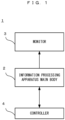
- FIG. 1 schematically shows the configuration of the information processing system according to the exemplary embodiment.
- an information processing system 1 includes an information processing apparatus main body 2, a monitor 3, and a controller 4.
- the information processing apparatus main body 2 executes predetermined information processing, and predetermined images and sounds generated as a result of the processing are outputted to the monitor 3.
- the controller 4 includes a communication section capable of wireless communication, and is used while being wirelessly connected with the information processing apparatus main body 2.
- the information processing apparatus main body 2 and the controller 4 may be connected with each other via a wire.
- Data indicating the content of a user's operation performed on the controller 4 is transmitted from the controller 4 to the information processing apparatus main body 2. Also, data for controlling operation of the controller 4 is transmitted from the information processing apparatus main body 2 to the controller 4.
- a controller control section (described later) included in the controller 4 performs various controls of the controller 4, including transmission and reception of such data.
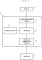
- FIG. 2 is a function block diagram showing an example of the internal configuration of the information processing apparatus main body 2.
- the information processing apparatus main body 2 includes a processor 11.
- the processor 11 is a circuit for controlling the information processing apparatus main body 2.
- the processor 11 executes various information processes to be executed in the information processing apparatus main body 2.
- the processor 11 may be formed of only a central processing unit (CPU), or may be formed of a system-on-a-chip (SoC) including a plurality of functions such as a CPU function and a graphics processing unit (GPU) function, for example.
- the processor 11 executes an information processing program (e.g., predetermined application program) stored in a storage section 12, thereby executing various information processes.
- the storage section 12 may be an internal storage medium such as a flash memory or a dynamic random access memory (DRAM), or may be configured using an external storage medium mounted to a slot (not shown), or the like, for example.
- DRAM dynamic random access memory
- a video/sound output section 14 is electrically connected with the processor 11, and outputs various images and sounds generated as a result of information processing executed by the processor 11, to the monitor 3.
- a controller communication section 13 is connected with the processor 11. The controller communication section 13 is for transmitting and receiving various data to and from the controller 4 connected wirelessly.
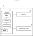
- FIG. 3 is a function block diagram showing the internal configuration of the controller 4.
- the controller 4 includes a controller control section 41, an analog stick 42, and a digital button section 44.
- the controller 4 may include a plurality of analog sticks 42.
- the controller 4 includes a battery and the like (not shown). Further, the controller 4 may include sensors such as an optical sensor and an inertial sensor.
- the controller control section 41 is a circuit for controlling the controller 4, and includes, for control, a microcomputer, a memory, a wireless module, an antenna, and the like. While using the memory as a storage area in processing, the controller control section 41 controls the wireless module for wirelessly transmitting transmission data to the information processing apparatus main body 2. In the memory, data of a preset library and the like described later are also stored. In addition, the controller control section 41 performs processing such as control for the analog stick 42 as described later, in accordance with data received by the wireless module from the information processing apparatus main body 2 via the antenna.
- the analog stick 42 is an operation element on which a direction can be inputted. A user can input a direction corresponding to a tilt direction by tilting the analog stick 42 (and input a magnitude corresponding to the tilt angle).
- the digital button section 44 includes at least one press-type button and/or trigger-type button.
- the configuration of the analog stick 42 in the exemplary embodiment will be described.
- a configuration using a magnetorheological fluid hereinafter, referred to as MRF
- MRF magnetorheological fluid
- the MRF has such characteristics that the MRF is a fluid when not subjected to a magnetic field, and comes into a semi-solid state (exhibits viscosity) when subjected to a magnetic field.
- the MRF also has characteristics of reacting to a magnetic field in several milliseconds.
- the viscosity of the MRF is controlled and the MRF is caused to act on a movable axis of the analog stick 42 of the controller 4, whereby movability of the analog stick 42 is dynamically controlled.
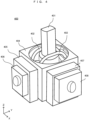
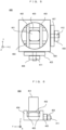
- FIG. 4 shows an example of the outer appearance of parts (hereinafter, stick device) composing the analog stick 42 assumed in the exemplary embodiment.
- FIG. 4 is a perspective view of a stick device 400 composing the analog stick 42.
- the stick device 400 includes a stick portion 401, an outer enclosure 404, an X-axis variable resistor 405, an X-axis MRF unit 406, a Y-axis variable resistor 407, and a Y-axis MRF unit 408.
- X-axis drive components 402 are provided adjacently to the stick portion 401.
- the stick device 400 further includes a Y-axis restoring force imparting section 403 described later.
- a mushroom-shaped cover is put over the stick portion 401 of the stick device 400.
- the stick portion 401 is a stick-shaped movable part.
- the X-axis variable resistor 405 and the Y-axis variable resistor 407 are for detecting the tilt degree of the stick portion 401.
- the X-axis MRF unit 406 and the Y-axis MRF unit 408 are for causing the MRF to act on the movable axis of the analog stick 42, as described above.
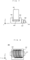
- FIG. 5 is a schematic view showing the positional relationship among parts when the stick device 400 is viewed from above.
- FIG. 6 and FIG. 7 are schematic views (sectional views) showing the positional relationship among parts when the stick device 400 is viewed from lateral sides.
- FIG. 6 is a view as seen from the left side in FIG. 5
- FIG. 7 is a view as seen from the lower side in FIG. 5 .
- the stick portion 401 is placed such that the center of the stick portion 401 is located at the center position of the outer enclosure 404.
- the stick portion 401 is placed such that the longitudinal direction thereof is parallel to the Z axis.
- the position of the center is referred to as an initial position
- an orientation in which the longitudinal direction of the stick portion 401 is parallel to the Z axis is referred to as an initial state.
- the X-axis drive components 402 and Y-axis drive components 403 are provided adjacently to the stick portion 401.
- the X-axis drive components 402 move the X-axis variable resistor 405 in coordination with movement in the X axis of the stick portion 401.
- the Y-axis drive components 403 move the Y-axis variable resistor 407 in coordination with movement in the Y axis of the stick portion 401. Therefore, although not directly shown in the drawings, the X-axis drive components 402 are connected to the X-axis variable resistor 405 so as to coordinate therewith (inside the outer enclosure 404). Similarly, the Y-axis drive components are connected to the Y-axis variable resistor 407 so as to coordinate therewith.
- the stick portion 401 in a case of tilting the stick portion 401, the stick portion 401 can be tilted up to the edge of a circular opening provided to the outer enclosure 404. That is, the circular opening restricts a basic movable area of the stick portion 401 (analog stick 4).
- a restriction member having a similar function may be provided at a base part of the stick portion 401.
- a housing of the controller 4 may be used as a restriction member.
- the housing may be provided with an opening having a predetermined shape, at a part where the stick device 400 is attached, so that the edge of the opening (shape) serves as a limitation boundary of the movable area of the analog stick 4 on the X axis and the Y axis.
- the opening has a circular shape, and therefore the two-dimensional area of the circular shape is the movable range of the analog stick 4 on the XY plane.
- the movable range limited by a physical restriction member as described above is referred to as a basic movable area.
- a restoring force imparting section which is a mechanism for restoring the stick portion 401 to the initial position is provided below the stick portion 401.
- the restoring force imparting section is formed by a member or the like that has therein an elastic body such as a coil spring and transmits a restoring force for returning to the initial position so as to bring back the stick portion 401 into a vertical condition.
- the restoring force imparting section works to restore the above drive components coordinating with the stick portion 401 to reference positions.
- a mechanism for imparting the restoring force is a known one and therefore the detailed description thereof is omitted.
- the restoring force imparting section having the elastic body may be placed vertically to the bottom surface of the outer enclosure 404. Then, the drive body may be kept in a reference state by forces being applied directly or indirectly to the drive components.
- the elastic body is used in the exemplary embodiment.
- a configuration using a magnet may be adopted as long as the same function is exerted.
- a configuration using a restoration mechanism that can actively control the restoring force may be adopted.
- a gear, a motor, and the like may be used in addition to or instead of the elastic body, the magnet, and the like.
- the stick device 400 has the X-axis variable resistor 405 and the Y-axis variable resistor 407 adjacently to the outer enclosure 404.
- the variable resistor is a known technology and therefore the detailed description thereof is omitted.
- the X-axis variable resistor 405 and the Y-axis variable resistor 407 are for detecting the tilt degree or the displacement direction of the stick portion 401.
- Each variable resistor is provided with a rotary shaft connected to the above drive components. The drive components rotate the rotary shaft in coordination with tilt and restoration movements of the stick portion 401. Then, a resistance value corresponding to the rotation of the rotary shaft is detected.
- the processor 11 or the controller control section 41 can determine the direction in which the stick portion 401 moves (hereinafter, displacement direction) and the tilt degree, etc. of the stick portion 401 (hereinafter, such information is simply referred to as "position of the analog stick").
- the displacement direction of the stick portion 401 is calculated with software means by the processor 11 or the controller control section 41.
- a main component that performs this calculation is not limited to the above ones.
- a configuration in which the displacement direction is mechanically detected using a predetermined sensor may be adopted.
- the stick device 400 has the X-axis MRF unit 406 adjacently on the outer side of the X-axis variable resistor 405. Similarly, the stick device 400 has the Y-axis MRF unit 408 adjacently on the outer side of the Y-axis variable resistor 407.
- the rotary shaft 411 used in the X-axis variable resistor 405 extends outward, and the X-axis MRF unit 406 is provided so as to surround the rotary shaft 411.
- the rotary shaft 412 used in the Y-axis variable resistor 407 extends outward, and the Y-axis MRF unit 408 is provided so as to surround the rotary shaft 412.
- a configuration in which the rotary shaft used in the X-axis variable resistor 405 is connected with a rotary shaft in the MRF unit so as to coordinate therewith may be adopted.
- the X-axis MRF unit 406 and the Y-axis MRF unit 408 may be collectively referred to as MRF units.
- FIG. 8 is a simplified schematic view illustrating a configuration example of the MRF unit.
- the rotary shaft 411 (a part thereof) connected (or joined) to the variable resistor penetrates an MRF container 421 containing an MRF.
- a magnetic field generation section 422 is provided so as to surround the outer side of the MRF container 421.
- the magnetic field generation section 422 is a coil, for example.
- the MRF unit is configured to be capable of causing current to flow through the magnetic field generation section 422. It is possible to generate a magnetic field by causing a predetermined amount of current to flow through the magnetic field generation section 422. Thus, the viscosity of the MRF in the MRF container 421 can be changed.
- the amount (i.e., amplitude) of current to be applied to the magnetic field generation section 422 it is possible to control the intensity of the magnetic field and thus control the magnitude of the viscosity of the MRF.
- By increasing the viscosity of the MRF it is possible to impart resistance against the rotational force of the rotary shaft 411. Since the rotary shaft 411 is connected so as to coordinate with the tilt of the stick portion 401 as described above, it is possible to impart a resistance force against a force to tilt the stick portion 401, through change in the viscosity of the MRF. That is, in the exemplary embodiment, the configuration is made such that movability of the stick portion 401 can be controlled by controlling the viscosity of the MRF as described above.
- FIG. 8 The view in FIG. 8 is shown in a simplified manner, for convenience of description. A supplementary description will be given about a more specific configuration of the MRF unit.
- a basic mechanism thereof is a structure similar to a disc brake of a bicycle or an automobile. Such a disc brake has a mechanism in which a rotating wheel is directly squeezed by mechanical parts to stop rotation by friction between parts.
- a frictional force is changed through control of the viscosity of the fluid, whereby movement in the rotational direction is restricted.
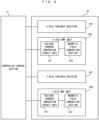
- FIG. 9 is a function block diagram showing the internal configuration of the analog stick 42.
- the analog stick 42 includes the X-axis variable resistor 405, the X-axis MRF unit 406, the Y-axis variable resistor 407, and the Y-axis MRF unit 408. These components are electrically connected with the controller control section 41, and predetermined data can be transmitted and received therebetween.
- the controller control section 41 can receive signals (e.g., voltage values) of the X-axis variable resistor 405 and the Y-axis variable resistor 407.
- the controller control section 41 can calculate the position of the stick portion 401, the displacement direction thereof, and the change speed (displacement speed) of the position.
- the controller control section 41 can transmit a calculation result to the information processing apparatus main body 2.
- the position of the analog stick 42 is represented as two-dimensional coordinates on a two-dimensional plane with the center position as the initial position (origin), for example.
- the controller control section 41 can transmit, to each MRF unit, a signal for controlling the viscosity of the MRF unit, as described below.
- the X-axis MRF unit 406 includes a voltage-current conversion circuit unit 431, and the magnetic field generation section 422 as described above, and both units are electrically connected to each other.
- the voltage-current conversion circuit unit 431 from the controller control section 41, current based on the voltage can be outputted to the magnetic field generation section 422.
- the Y-axis MRF unit 408 includes a voltage-current conversion circuit unit 431 and the magnetic field generation section 422, and the same control as described above can be performed.
- movability (viscosity) of the analog stick 42 is represented by the sum of values on two axes, i.e., the X axis and the Y axis.
- movability (viscosity) of the analog stick 42 is represented by the sum of values on two axes, i.e., the X axis and the Y axis.
- the exemplary embodiment By performing viscosity control for the MRF with the above configuration, in the exemplary embodiment, it is possible to present various feelings to the user (user's fingers) operating the analog stick 42. For example, by controlling the viscosity of the MRF in accordance with a predetermined scene in an application, it is possible to give various feelings corresponding to the scene, to the fingers of the user operating the analog stick 42. In a case where the controller 4 includes a plurality of analog sticks 42, it is possible to control the viscosity of each analog stick individually. Thus, it is possible to provide an unprecedented new operation feeling to the user.
- the viscosity of the MRF is controlled in accordance with the present position of the analog stick.
- two kinds of viscosities are used: a viscosity (hereinafter, first viscosity) at such a level that the analog stick 42 can be freely moved without a resistance feeling and a high viscosity (hereinafter, second viscosity) at such a level that the analog stick 42 cannot be moved with a normal force degree.
- first viscosity a viscosity at such a level that the analog stick 42 can be freely moved without a resistance feeling
- second viscosity at such a level that the analog stick 42 cannot be moved with a normal force degree.
- an area to have the first viscosity and an area to have the second viscosity are defined in advance.
- FIG. 10 shows an example of definition of these areas. In FIG.
- a rectangular area including a center part of the basic movable area is defined as a first area.
- the other area (area indicated by a hatched pattern) surrounding the entire periphery of the first area is defined as a second area.
- the first viscosity is assigned to the first area
- the second viscosity is assigned to the second area. Then, the viscosity of the MRF is controlled to be the first viscosity or the second viscosity in accordance with in which area the position of the analog stick 42 is.
- the viscosity of the MRF is controlled to be the first viscosity
- the viscosity of the MRF is controlled to be the second viscosity.
- the first viscosity is set over the entire movable area of the analog stick 42, i.e., the entirety of the basic movable area.
- the second viscosity is set over the entirety of the basic movable area, including the first area in FIG. 10 .
- the user can eventually feel that the movable areas as shown in FIG. 10 seem to be present.
- the second viscosity is a high viscosity at such a level that the analog stick 42 cannot be moved with a normal force degree. Nevertheless, the second viscosity is also assumed to be such a viscosity that the analog stick 42 can be moved if a considerably greater force than a normal force degree is applied with the fingers (though the operation feeling is considerably "heavy"). In other words, the second viscosity is such a viscosity that the MRF serves as a resistance that substantially does not allow the operation element to be displaced.
- the second viscosity may be such a viscosity that the MRF serves as a resistance that allows movement at any rate with a force not as great as a "considerably great force” though a greater force than for the first viscosity is needed.
- the force degree is represented by numerical values 1 to 10
- the normal force degree force degree for first viscosity
- the second viscosity is such a viscosity that the operation element cannot be displaced unless a force close to "10" is applied.
- the second viscosity may be such a viscosity that the operation element can be displaced at any rate with a force degree of about "5".
- the first viscosity is set at such a viscosity that the analog stick 42 can be freely moved without a resistance feeling.
- refraining from performing viscosity control may be considered to correspond to control for the first viscosity.
- both of the first area and the second area may have any shapes and may be arranged at any positions.
- a plurality of combinations of patterns of the first area and the second area (hereinafter, referred to as area patterns) may be prepared, and may be selectively used in accordance with the situation.
- area patterns may be prepared, and may be selectively used in accordance with the situation.
- area patterns to be used are selected in accordance with the situation and the scene in the application being executed will be described.
- area patterns to be used may be changed between a scene in which the user operates a menu screen or the like and a scene in which the user operates a predetermined operation object.
- control based on an area pattern in which the first viscosity is set over the entire basic movable area may be performed (that is, the second area is not present in this area pattern).
- viscosity control based on a predetermined area pattern using also the second area may be performed so that an operation feeling corresponding to the characteristics of the operation object can be provided.
- a menu screen area pattern corresponding to the layout of the menu screen may be used, and on the other hand, in the scene in which the user operates a predetermined operation object, an operation object area pattern may be used separately from the above one. In this way, by selectively using area patterns in accordance with the situation and the scene in the application, it is possible to provide the user with various operation feelings.
- the following control may be performed.
- an application in which an operation target object is moved in a virtual three-dimensional space by using the analog stick 42 is assumed.
- a parameter called a vitality value is set for the operation target object and the operation target object becomes unable to move when the vitality value has become 0.
- the operation target object can be operated over the entire basic movable area, but when the vitality value has become a certain value or less, for example, viscosity control based on an area pattern as shown in FIG. 10 is performed.
- the user can feel that the operation is limited within the first area, and when the operation target object falls into a disadvantageous state, for example, "difficulty in movement due to vitality reduction" can be expressed by an operation feeling on the analog stick 42.
- control may be performed such that the content of the first area and the second movable area are set in accordance with the terrain and the nature of a place in the virtual space where the operation target object is located, or the surrounding environment therearound.
- the place where the operation target object is located is a place where movement is relatively easy (e.g., a place where the movement speed of the operation object according to an input on the analog stick is set to be relatively fast)
- an operation can be performed with the entire basic movable area used.
- viscosity control using a predetermined area pattern is performed, for example.
- the area pattern in this case, a range having a circular shape whose size is about half the size of the basic movable area is defined as the first area having the first viscosity, for example.
- control may be performed so as to use an area pattern corresponding to the obstacle (the positional relationship between the obstacle and the operation object). For example, when walls are present on the front side and the right side of the operation object, viscosity control may be performed using an area pattern having a shape defined so as to prevent the analog stick 42 from tilting upward and rightward.
- control may be performed such that, normally, viscosity control is performed using an area pattern that limits the movable range, and in accordance with the situation in the application, the area pattern is changed to an area pattern in which the entire basic movable area can be used (that is, the movable area expands).
- control in an application in which an operation target object can be selected from a plurality of objects, control may be performed so as to set an area pattern (that differs) in accordance with the selected operation target object.
- selection may be arbitrarily performed by the user, or may be performed automatically.
- area patterns associated with respective operation target objects may be defined in advance. Then, without performing viscosity control on a selection screen for operation target objects, after an operation target object is selected, viscosity control may be performed on the basis of the area pattern associated with the selected operation target object.
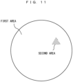
- an area pattern as shown in FIG. 11 may be used.
- an area having substantially a triangular shape is defined as the second area and the other area is defined as the first area.
- the first area corresponds to the first viscosity
- the second area corresponds to the second viscosity.
- FIG. 12 shows an example of data stored in the storage section 12 of the information processing apparatus 2.
- the storage section 12 stores an application program 511, area definition data 512, used area data 514, viscosity definition data 515, operation data 516, and the like.
- the application program 511 is a program for implementing a predetermined application.
- the area definition data 512 is data defining the first area and the second area as described above.
- a configuration using only one area pattern may be adopted, but in this example, a plurality of area patterns are used. Therefore, in the area definition data 512, pieces of information defining the contents of the respective area patterns are stored as pieces of area pattern information 513.
- each area pattern information 513 may be any data structure as long as the range of each area and what viscosity is set can be specified.
- the following data structure is conceivable. That is, the entire basic movable area may be represented by two-dimensional arrangement of 100x100 locations, and information designating which of control for the first viscosity and control for the second viscosity is to be performed at the coordinates of each location is defined for the respective locations.
- the used area data 514 is data for designating the area pattern to be used at present, among the plurality of area patterns.
- the viscosity definition data 515 is a parameter for realizing the first viscosity and the second viscosity described above. Specifically, for the first viscosity and the second viscosity, the parameter designates three values, i.e., the amplitude, the frequency, and the application time to be outputted from the controller control section 41 to the voltage-current conversion circuit unit 431 (hereinafter, the three values are referred to as a viscosity parameter).
- a voltage command value whose waveform has components of the viscosity parameter is outputted to the voltage-current conversion circuit unit 431, and current based on the voltage command value is outputted to the magnetic field generation section 422.
- the magnetic field thus generated can change the viscosity of the MRF.
- a viscosity parameter corresponding to the first viscosity or a viscosity parameter corresponding to the second viscosity is determined, and the viscosity parameter is outputted from the application (via system software) to the controller control section 41.
- the operation data 516 data outputted from the controller control section 41 at a predetermined cycle is stored.
- the operation data 516 includes data indicating the position of the analog stick 42 and data indicating the press states of various buttons.
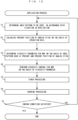
- FIG. 13 is a flowchart showing an example of the viscosity control processing in the exemplary embodiment.
- the processor 11 determines the area pattern to be used, in accordance with the situation and the scene in the application at this time.
- the determination method may be any method. For example, the determination may be performed on the basis of whether or not the vitality value of an operation target object is a predetermined value or less, whether or not the position of the operation target object in a virtual space is in a predetermined area, and the like.
- information specifying the determined area pattern is set in the used area data 514.
- step S2 the processor 11 calculates the present position of the analog stick 42 on the basis of the operation data 516.
- step S3 the processor 11 determines the viscosity parameter on the basis of the area pattern set in the used area data 514 and the present position of the analog stick 42. That is, a viscosity parameter corresponding to the first viscosity or a viscosity parameter corresponding to the second viscosity is determined in accordance with the present position of the analog stick 42.
- presets of viscosity parameters may be provided in a memory of the controller control section 41, and the preset may be designated in the processing in step S3.
- step S4 the processor 11 performs viscosity control for the MRF on the basis of the determined viscosity parameter.
- the processor 11 outputs the viscosity parameter from the application (via system software) to the controller control section 41. Accordingly, the controller control section 41 controls the intensity of a magnetic field to be applied to the MRF unit, on the basis of the viscosity parameter. Thus, the viscosity of the MRF is controlled.
- the viscosity of the MRF may be controlled through control (mainly) by the controller control section 41 on the basis of the preset designated in step S3, for example, irrespective of the output from the application.
- step S5 the processor 11 executes other processing in the application. For example, processing of moving the operation object on the basis of the present position of the analog stick 42, and the like are performed.
- step S6 the processor 11 generates an image in which the above processing result is reflected, and outputs the image to the monitor 3.
- step S7 the processor 11 determines whether or not a condition for ending the application is satisfied. For example, whether or not an instruction operation to end the application has been performed, or the like is determined. As a result of the determination, the ending condition is satisfied (YES in step S7), the application process is ended. If the ending condition is not satisfied (NO in step S7), the process returns to step S 1, so as to be repeated.
- viscosity control for the MRF is performed on the basis of the present position of the analog stick 42. Further, area patterns defining the shapes, sizes, and ranges of areas are prepared, and a plurality of area patterns are selectively used in accordance with the situation in the application. Thus, it is possible to let the user receive various operation feelings in accordance with the situation in the application.
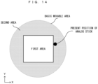
- the second example for example, it is assumed that two areas which are the first area and the second area as shown in FIG. 10 are defined as an area pattern, and processing in the second example is performed in such a case where the present position of the analog stick 42 is located in the second area as shown in FIG. 14 , for example.
- the analog stick 42 is located outside the boundary of the first area and thus the viscosity of the MRF has changed from the first viscosity (low viscosity) to the second viscosity (high viscosity), so that the analog stick 42 no longer moves (with a normal force), for example.
- the displacement direction of the analog stick 42 from this position is detected or calculated by a predetermined method (described later).
- control is performed so as to reduce the viscosity.
- control is performed so as to increase the viscosity. That is, in the second example, in a case where the analog stick 42 is located outside the first area, whether the analog stick 42 is to move away from the first area or to approach the first area is determined, and the viscosity is controlled in accordance with the determination result.
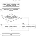
- FIG. 15 shows an example of a flow of the control process in the second example. This process can be performed in a case where the present position of the analog stick is outside the first area as shown in FIG. 14 .
- the processor 11 calculates or detects the displacement direction of the analog stick 42.
- the processor 11 determines whether the displacement direction is a direction of approaching the first area or a direction of moving away from the first area.
- the method for calculation/detection and determination for the displacement direction may be any method. As examples, two methods will be briefly described below.
- the second viscosity is a "high viscosity at such a level that the analog stick 42 cannot be moved with a normal force degree", but is also such a viscosity that the analog stick 42 can be moved if a greater force than a normal force degree is applied with the fingers. Therefore, the description is based on the assumption that the analog stick 42 can be moved also outside the first area with a greater force than a normal force degree (though movement is slow).
- the processor 11 calculates, for example, a movement vector, on the basis of the coordinates before movement and the coordinates after movement of the analog stick 42. Then, the processor 11 determines whether the direction of the movement vector is a direction of approaching the first area or a direction of moving away from the first area. With this method, the displacement direction of the analog stick 42 can be calculated and determined.
- a second method a high-accuracy sensor capable of detecting the displacement direction is mounted to the analog stick 42, and the detection result is used.
- a force sensor is mounted to the analog stick 42.
- the processor 11 can determine the displacement direction on the basis of the detection result of the force sensor, and can determine whether or not the displacement direction is a direction of approaching the first area.
- step S23 the processor 11 performs control so as to make the viscosity of the MRF smaller than the present viscosity.
- the viscosity may be made smaller by multiplying the present viscosity by a predetermined coefficient defined in advance or a coefficient according to the magnitude of the above movement vector or the magnitude of the force detected by the force sensor. This can make it easier to move the analog stick 42 into the first area.
- step S24 the processor 11 performs control so as to make the viscosity of the MRF greater than the present viscosity. This can make it more difficult to move the analog stick 42.
- control may be performed so as to keep the present viscosity, instead of making the viscosity greater. Also in this case, it is possible to keep the difficulty in moving the analog stick 42.
- viscosity control based on the displacement direction of the analog stick 42 is performed.
- the analog stick 42 is located outside the first area in the area pattern as shown in FIG. 14 , in particular, when the analog stick 42 is located near the boundary between the two areas, favorable viscosity control can be performed for an operation feeling on the analog stick 42.
- the area pattern to be used is changed (switched) in accordance with the situation or the like in the application, before actual change, for example, a notification that "the movable range of the analog stick 42 will be changed now, so please return the position of the analog stick 42 to the initial position" may be issued, and control of changing the area pattern to be used may be performed after the position of the analog stick 42 returns to the initial position.
- the position of the return destination is not limited to the initial position and may be a predetermined position.
- the timing of performing such control is not limited to a time before the area pattern is changed.
- processing may be performed such that viscosity control is not started until the position of the analog stick 42 actually returns.
- a notification indicating that fact may be displayed. This notification may be displayed for a predetermined time period after the area pattern to be used is changed, and then may be deleted, or the notification may continue being displayed while the area pattern to be used is changed.
- an image indicating the size and/or the shape (relative to the basic movable area) of the area pattern being used may be displayed together with or instead of the above notification.
- a predetermined button may be defined as a button for switching, and a first area pattern and a second area pattern are switched therebetween every time the button is pressed.
- control may be performed such that a predetermined area pattern is made effective only while the button is being pressed.
- a button having such a function may be assigned through button setting in a predetermined application.
- such a button may be assigned as a function of the system.
- the definition content of the area pattern may be allowed to be arbitrarily set by the user. This is for making it possible to reflect the preference or individual difference of the force degree exerted with the fingers by each user. For example, there may be a user who desires, as a favorite operation feeling, that the distance from the center to the outer edge part in the basic movable area, i.e., the distance in a case of performing an input by maximally tilting the analog stick, is shorter than the standard distance. In this case, for example, the following operation and setting processing may be performed. First, a predetermined setting screen is displayed, and a circular image corresponding to the basic movable area is displayed.
- a slider for changing the size of the circle is also displayed (the size of the basic movable area is defined as 100%). Then, the user is let to designate the size of the circle by the slider and perform an operation of tilting the analog stick from the center position to the outer edge position of the circle image. This operation is repeated, and when the user has found a preferable circle size, the outside of the circle set by the slider at this time is set as the second area having the second viscosity, and the inside of the circle is set as the first area having the first viscosity, thus defining an area pattern, which is then stored as an area pattern set by the user.
- the size of the circle in the first area set as described above is 80% of the basic movable area.
- tilting of the analog stick 42 is stopped at a position corresponding to 80% in the basic movable area, and thus an input of tilting by 100% cannot be performed with respect to the basic movable area. Therefore, during usage of the area pattern set by the user in this case, the input value may be corrected so that tilting by 80% with respect to the basic movable area is regarded as an input of tilting by 100% (regarded as a state in which the analog stick 42 is fully tilted).
- a controller having two analog sticks 42 e.g., a "right stick” and a "left stick"
- area patterns to be used for the "right stick” and the "left stick” may be different.
- the area pattern to be used for the "right stick” may be defined such that movement can be performed only in the left-right direction
- the area pattern to be used for the "left stick” may be defined such that movement can be performed only in the up-down direction.
- the positions of the MRF units shown above are merely an example and the MRF units may be at positions other than the above ones.
- the MRF units may be provided at any positions as long as it is possible to cause an influence on ease of movement of the stick portion 401.
- control is performed so as to increase or reduce the present viscosity in accordance with whether or not the displacement direction is a direction of approaching the first area.
- various other controls may be performed without limitation to the above control. For example, when the displacement direction is a direction of moving away from the first area, an alarm indication may be displayed.
- control may be performed so that the entire basic movable area has the first viscosity. That is, execution of the viscosity control for limiting the movable area as described above may be stopped (limitation of the movable area is canceled).
- the viscosity definition data 515 data in which parameters for realizing the first viscosity and the second viscosity are defined in advance is used as the viscosity definition data 515.
- these parameters may be calculated at each time in accordance with the situation in the application.
- the information processing system in which the information processing apparatus main body 2, the monitor 3, and the controller 4 are configured separately from each other has been shown.
- the above configuration and control are also applicable to apparatuses such as a hand-held information processing apparatus in which an information processing apparatus main body, a predetermined display section, and an analog stick and/or a button are integrated.
- the information processing system can provide a new operation feeling to a user, and is effectively applicable to a controller and the like used in various information processing apparatuses such as a personal computer.
Landscapes
- Engineering & Computer Science (AREA)
- General Engineering & Computer Science (AREA)
- Theoretical Computer Science (AREA)
- Physics & Mathematics (AREA)
- General Physics & Mathematics (AREA)
- Human Computer Interaction (AREA)
- Automation & Control Theory (AREA)
- Position Input By Displaying (AREA)
- User Interface Of Digital Computer (AREA)
Applications Claiming Priority (1)
| Application Number | Priority Date | Filing Date | Title |
|---|---|---|---|
| PCT/JP2020/046104 WO2022123737A1 (fr) | 2020-12-10 | 2020-12-10 | Système de traitement d'informations, contrôleur, procédé de traitement d'informations, et programme de traitement d'informations |
Publications (2)
| Publication Number | Publication Date |
|---|---|
| EP4227771A1 true EP4227771A1 (fr) | 2023-08-16 |
| EP4227771A4 EP4227771A4 (fr) | 2024-06-12 |
Family
ID=81973425
Family Applications (1)
| Application Number | Title | Priority Date | Filing Date |
|---|---|---|---|
| EP20965119.9A Pending EP4227771A4 (fr) | 2020-12-10 | 2020-12-10 | Système de traitement d'informations, contrôleur, procédé de traitement d'informations, et programme de traitement d'informations |
Country Status (5)
| Country | Link |
|---|---|
| US (1) | US12164709B2 (fr) |
| EP (1) | EP4227771A4 (fr) |
| JP (1) | JP7610618B2 (fr) |
| CN (1) | CN116438504A (fr) |
| WO (1) | WO2022123737A1 (fr) |
Families Citing this family (5)
| Publication number | Priority date | Publication date | Assignee | Title |
|---|---|---|---|---|
| JP7568743B2 (ja) * | 2020-11-18 | 2024-10-16 | 任天堂株式会社 | 情報処理システム、コントローラ、情報処理方法、情報処理プログラム |
| JP2024064224A (ja) * | 2022-10-27 | 2024-05-14 | オムロン株式会社 | 操作装置 |
| WO2024105772A1 (fr) * | 2022-11-15 | 2024-05-23 | 株式会社ソニー・インタラクティブエンタテインメント | Dispositif de traitement d'informations, dispositif d'actionnement, procédé de traitement d'informations et programme |
| WO2024252764A1 (fr) * | 2023-06-07 | 2024-12-12 | 田中誠 | Dispositif de commande |
| WO2025063109A1 (fr) * | 2023-09-21 | 2025-03-27 | 株式会社ソニー・インタラクティブエンタテインメント | Dispositif d'entrée |
Family Cites Families (11)
| Publication number | Priority date | Publication date | Assignee | Title |
|---|---|---|---|---|
| JPH07213740A (ja) * | 1994-01-28 | 1995-08-15 | Namco Ltd | 操作体を用いたゲーム機械 |
| US7113166B1 (en) * | 1995-06-09 | 2006-09-26 | Immersion Corporation | Force feedback devices using fluid braking |
| JP4581767B2 (ja) * | 2005-03-16 | 2010-11-17 | 株式会社デンソー | 通信装置 |
| US20140004941A1 (en) * | 2012-06-29 | 2014-01-02 | Sony Computer Entertainment Inc. | Conversion of haptic events into screen events |
| EP2994268B1 (fr) | 2013-05-07 | 2017-03-08 | ICS Ice Cleaning Systems S.r.o. | Dispositif de broyage et d'acheminement de particules solides de glace sèche pour des dispositifs pour mélanger des particules solides de glace sèche avec un flux de fluide gazeux |
| JP2014228703A (ja) * | 2013-05-22 | 2014-12-08 | トヨタ自動車株式会社 | 地図表示制御装置 |
| JP2016007345A (ja) | 2014-06-24 | 2016-01-18 | 株式会社ソニー・コンピュータエンタテインメント | ゲームシステム |
| JP6083884B2 (ja) | 2015-06-12 | 2017-02-22 | 任天堂株式会社 | 支持装置、充電装置、および、操作システム |
| FR3056315B1 (fr) * | 2016-09-21 | 2018-09-28 | Commissariat A L'energie Atomique Et Aux Energies Alternatives | Interface haptique a au moins deux degres de liberte presentant un ressenti haptique ameliore |
| JP6817444B2 (ja) * | 2017-07-21 | 2021-01-20 | アルプスアルパイン株式会社 | 入力装置、入力装置制御方法、および制御プログラム |
| JP2020035376A (ja) * | 2018-08-31 | 2020-03-05 | Smk株式会社 | 粘性流体デバイスの駆動制御方法及び駆動制御装置 |
-
2020
- 2020-12-10 JP JP2022567980A patent/JP7610618B2/ja active Active
- 2020-12-10 CN CN202080107181.1A patent/CN116438504A/zh active Pending
- 2020-12-10 WO PCT/JP2020/046104 patent/WO2022123737A1/fr not_active Ceased
- 2020-12-10 EP EP20965119.9A patent/EP4227771A4/fr active Pending
-
2023
- 2023-05-11 US US18/316,018 patent/US12164709B2/en active Active
Also Published As
| Publication number | Publication date |
|---|---|
| EP4227771A4 (fr) | 2024-06-12 |
| US12164709B2 (en) | 2024-12-10 |
| JP7610618B2 (ja) | 2025-01-08 |
| CN116438504A (zh) | 2023-07-14 |
| US20230280849A1 (en) | 2023-09-07 |
| JPWO2022123737A1 (fr) | 2022-06-16 |
| WO2022123737A1 (fr) | 2022-06-16 |
Similar Documents
| Publication | Publication Date | Title |
|---|---|---|
| US12164709B2 (en) | Information processing system, controller, information processing method, and computer-readable non-transitory storage medium having stored therein information processing program | |
| US11221730B2 (en) | Input device for VR/AR applications | |
| US10540022B2 (en) | Interactive input controls in a simulated three-dimensional (3D) environment | |
| JP6893868B2 (ja) | 空間依存コンテンツのための力覚エフェクト生成 | |
| EP3489803A1 (fr) | Systèmes et procédés pour fournir un retour haptique selon des entrées basées sur l'inclinaison | |
| JP2023500025A (ja) | 物理オブジェクトの仮想現実への移植 | |
| EP2839355A2 (fr) | Procédé et dispositif de commande pour déplacement d'un objet virtuel et retour vers l'utilisateur | |
| JPWO2022123737A5 (fr) | ||
| KR100931926B1 (ko) | 자세를 감지하여 메뉴 아이콘이 움직이는 이동통신 단말기 | |
| EP1880747B1 (fr) | Dispositif de stockage pour logiciel de jeu, dispositif de jeu et méthode de contrôle de jeu | |
| CN116529696A (zh) | 信息处理系统、控制器、信息处理方法、信息处理程序 | |
| EP4227779A1 (fr) | Système de traitement d'informations, dispositif de commande, procédé de traitement d'informations, et programme de traitement d'informations | |
| EP4085313B1 (fr) | Réalité arbitrée | |
| JP7441325B2 (ja) | 情報処理システム、情報処理プログラムおよび情報処理方法 | |
| US8970491B2 (en) | Computer system, computer system control method, program, and information storage medium | |
| JP2023166046A (ja) | 情報処理プログラム、情報処理装置、情報処理システム、および情報処理方法 | |
| KR20180122869A (ko) | 3차원 영상 처리 방법 및 장치 | |
| US20200286298A1 (en) | Systems and methods for a user interaction proxy | |
| EP4575724A1 (fr) | Dispositif de traitement d'informations et procédé de traitement d'informations | |
| JP2025160875A (ja) | プログラム、情報処理システム、および情報処理方法 | |
| JP3937179B2 (ja) | ゲーム画面の表示制御方法、キャラクタの移動制御方法およびゲーム機並びにプログラムを記録した記録媒体 | |
| WO2018201150A1 (fr) | Système de commande pour un environnement tridimensionnel | |
| CN118034826A (zh) | 扩展现实空间中应用的控制方法、装置、设备和介质 | |
| HK1174711A (en) | Push actuation of interface controls |
Legal Events
| Date | Code | Title | Description |
|---|---|---|---|
| STAA | Information on the status of an ep patent application or granted ep patent |
Free format text: STATUS: THE INTERNATIONAL PUBLICATION HAS BEEN MADE |
|
| PUAI | Public reference made under article 153(3) epc to a published international application that has entered the european phase |
Free format text: ORIGINAL CODE: 0009012 |
|
| STAA | Information on the status of an ep patent application or granted ep patent |
Free format text: STATUS: REQUEST FOR EXAMINATION WAS MADE |
|
| 17P | Request for examination filed |
Effective date: 20230512 |
|
| AK | Designated contracting states |
Kind code of ref document: A1 Designated state(s): AL AT BE BG CH CY CZ DE DK EE ES FI FR GB GR HR HU IE IS IT LI LT LU LV MC MK MT NL NO PL PT RO RS SE SI SK SM TR |
|
| DAV | Request for validation of the european patent (deleted) | ||
| DAX | Request for extension of the european patent (deleted) | ||
| A4 | Supplementary search report drawn up and despatched |
Effective date: 20240514 |
|
| RIC1 | Information provided on ipc code assigned before grant |
Ipc: G06F 3/01 20060101AFI20240508BHEP |
|
| STAA | Information on the status of an ep patent application or granted ep patent |
Free format text: STATUS: EXAMINATION IS IN PROGRESS |
|
| 17Q | First examination report despatched |
Effective date: 20260226 |