EP4228046B1 - Appareil de lutte contre l'incendie, ensemble boîtier, batterie, appareil de consommation d'énergie et procédé de préparation de batterie - Google Patents
Appareil de lutte contre l'incendie, ensemble boîtier, batterie, appareil de consommation d'énergie et procédé de préparation de batterie Download PDFInfo
- Publication number
- EP4228046B1 EP4228046B1 EP23170778.7A EP23170778A EP4228046B1 EP 4228046 B1 EP4228046 B1 EP 4228046B1 EP 23170778 A EP23170778 A EP 23170778A EP 4228046 B1 EP4228046 B1 EP 4228046B1
- Authority
- EP
- European Patent Office
- Prior art keywords
- fire
- fighting
- gas
- pipe
- battery
- Prior art date
- Legal status (The legal status is an assumption and is not a legal conclusion. Google has not performed a legal analysis and makes no representation as to the accuracy of the status listed.)
- Active
Links
Images


Classifications
-
- H—ELECTRICITY
- H01—ELECTRIC ELEMENTS
- H01M—PROCESSES OR MEANS, e.g. BATTERIES, FOR THE DIRECT CONVERSION OF CHEMICAL ENERGY INTO ELECTRICAL ENERGY
- H01M10/00—Secondary cells; Manufacture thereof
- H01M10/42—Methods or arrangements for servicing or maintenance of secondary cells or secondary half-cells
-
- A—HUMAN NECESSITIES
- A62—LIFE-SAVING; FIRE-FIGHTING
- A62C—FIRE-FIGHTING
- A62C3/00—Fire prevention, containment or extinguishing specially adapted for particular objects or places
- A62C3/16—Fire prevention, containment or extinguishing specially adapted for particular objects or places in electrical installations, e.g. cableways
-
- A—HUMAN NECESSITIES
- A62—LIFE-SAVING; FIRE-FIGHTING
- A62C—FIRE-FIGHTING
- A62C35/00—Permanently-installed equipment
- A62C35/58—Pipe-line systems
- A62C35/62—Pipe-line systems dry, i.e. empty of extinguishing material when not in use
-
- H—ELECTRICITY
- H01—ELECTRIC ELEMENTS
- H01M—PROCESSES OR MEANS, e.g. BATTERIES, FOR THE DIRECT CONVERSION OF CHEMICAL ENERGY INTO ELECTRICAL ENERGY
- H01M50/00—Constructional details or processes of manufacture of the non-active parts of electrochemical cells other than fuel cells, e.g. hybrid cells
- H01M50/30—Arrangements for facilitating escape of gases
- H01M50/35—Gas exhaust passages comprising elongated, tortuous or labyrinth-shaped exhaust passages
- H01M50/358—External gas exhaust passages located on the battery cover or case
-
- H—ELECTRICITY
- H01—ELECTRIC ELEMENTS
- H01M—PROCESSES OR MEANS, e.g. BATTERIES, FOR THE DIRECT CONVERSION OF CHEMICAL ENERGY INTO ELECTRICAL ENERGY
- H01M50/00—Constructional details or processes of manufacture of the non-active parts of electrochemical cells other than fuel cells, e.g. hybrid cells
- H01M50/30—Arrangements for facilitating escape of gases
- H01M50/383—Flame arresting or ignition-preventing means
-
- H—ELECTRICITY
- H01—ELECTRIC ELEMENTS
- H01M—PROCESSES OR MEANS, e.g. BATTERIES, FOR THE DIRECT CONVERSION OF CHEMICAL ENERGY INTO ELECTRICAL ENERGY
- H01M50/00—Constructional details or processes of manufacture of the non-active parts of electrochemical cells other than fuel cells, e.g. hybrid cells
- H01M50/60—Arrangements or processes for filling or topping-up with liquids; Arrangements or processes for draining liquids from casings
- H01M50/673—Containers for storing liquids; Delivery conduits therefor
-
- A—HUMAN NECESSITIES
- A62—LIFE-SAVING; FIRE-FIGHTING
- A62C—FIRE-FIGHTING
- A62C3/00—Fire prevention, containment or extinguishing specially adapted for particular objects or places
- A62C3/07—Fire prevention, containment or extinguishing specially adapted for particular objects or places in vehicles, e.g. in road vehicles
-
- Y—GENERAL TAGGING OF NEW TECHNOLOGICAL DEVELOPMENTS; GENERAL TAGGING OF CROSS-SECTIONAL TECHNOLOGIES SPANNING OVER SEVERAL SECTIONS OF THE IPC; TECHNICAL SUBJECTS COVERED BY FORMER USPC CROSS-REFERENCE ART COLLECTIONS [XRACs] AND DIGESTS
- Y02—TECHNOLOGIES OR APPLICATIONS FOR MITIGATION OR ADAPTATION AGAINST CLIMATE CHANGE
- Y02E—REDUCTION OF GREENHOUSE GAS [GHG] EMISSIONS, RELATED TO ENERGY GENERATION, TRANSMISSION OR DISTRIBUTION
- Y02E60/00—Enabling technologies; Technologies with a potential or indirect contribution to GHG emissions mitigation
- Y02E60/10—Energy storage using batteries
-
- Y—GENERAL TAGGING OF NEW TECHNOLOGICAL DEVELOPMENTS; GENERAL TAGGING OF CROSS-SECTIONAL TECHNOLOGIES SPANNING OVER SEVERAL SECTIONS OF THE IPC; TECHNICAL SUBJECTS COVERED BY FORMER USPC CROSS-REFERENCE ART COLLECTIONS [XRACs] AND DIGESTS
- Y02—TECHNOLOGIES OR APPLICATIONS FOR MITIGATION OR ADAPTATION AGAINST CLIMATE CHANGE
- Y02P—CLIMATE CHANGE MITIGATION TECHNOLOGIES IN THE PRODUCTION OR PROCESSING OF GOODS
- Y02P70/00—Climate change mitigation technologies in the production process for final industrial or consumer products
- Y02P70/50—Manufacturing or production processes characterised by the final manufactured product
Definitions
- a battery As an energy storage device, a battery is a core component of a hybrid vehicle and an electric vehicle. When the battery is overcharged or over-discharged or shortcircuited, thermal runaway occurs, and a combustible gas emitted may explode and cause a fire. Therefore, fireproofing processing requires to be performed on the battery.
- D1 ( CN211789233U ) provides a safe exhaust device for a battery pack which is characterized in that one end of an exhaust pipeline is connected to the position of an explosion-proof valve at a pressure relief and ventilation position of the battery pack through a fastening assembly, a first external thread is arranged at the connecting position of the exhaust pipeline and the explosion-proof valve, and flame-retardant gas is filled in the exhaust pipeline;
- the fastening assembly comprises a fastening bolt and a first sealing gasket, the fastening bolt penetrates through the exhaust pipeline and tightly presses the first sealing gasket at the interface gap between the exhaust pipeline and the battery pack through a first external thread;
- the flame-retardant gas assembly is connected to the side part of the exhaust pipeline and is used for inputting or outputting flame-retardant gas into or out of the exhaust pipeline; waterproof breather valve is connected in exhaust duct's end, and waterproof breather valve is used for the exhaust outlet as exhaust duct.
- an embodiment of the present application provides a fire-fighting apparatus configured for a battery, including: a pipe, a gas release mechanism, and a blocking structure.
- the pipe has an air inlet end and an air outlet end, and the air inlet end is configured to be connected to a box of the battery, so that a combustible gas generated when thermal runaway occurs in the battery is capable of entering the pipe from the box via the air inlet end and is discharged from the pipe via the air outlet end; and the gas release mechanism is configured to be connected to the pipe, and the gas release mechanism is configured to release a fire-fighting gas into the pipe when thermal runaway occurs in the battery; where a blocking structure is provided in the pipe, and the blocking structure is configured to block the combustible gas and the fire-fighting gas and change a flow direction, so that the combustible gas and the fire-fighting gas are capable of being mixed before being discharged from the pipe;
- a flow path of the gas is a meandering path.
- the baffle plate can not only mix gases, but also prevent a high-temperature particle entering the pipe from the box through flowing out of the pipe, thereby avoiding risks that may be caused by the outflow of the high-temperature particle, such as a fire.
- the fire-fighting apparatus provided by the foregoing solution of the present application could reduce the risk of open flames when thermal runaway occurs in the battery, while suppressing the spread of thermal runaway in the battery, which extends the safety evacuation time, and achieves the purpose of fire prevention and safety protection.
- the blocking structure is configured to provide a flow path of at least part of a gas in the pipe a meandering shape.
- the plurality of baffle plates at least include a pair of arc-shaped plates, and concave surfaces of the pair of arc-shaped plates are disposed opposite to each other.
- the spiral blade can provide a flow path of the mixed gas a spiral shape, which is beneficial for a full mixing of the fire-fighting gas and the combustible gas.
- the blocking structure includes a plurality of spiral blades, the plurality of spiral blades are arranged in an extension direction of the pipe, and rotary directions of two adjacent spiral blades are opposite.
- the gas release mechanism is provided outside the pipe, a through hole is provided on a wall of the pipe, and the gas release mechanism is connected to the through hole, to release the fire-fighting gas into the pipe from the through hole.
- the through hole is multiple in quantity, and the multiple through holes are arranged at intervals in an extension direction of the pipe.
- the gas release mechanism includes: a fire-fighting medium, a housing, and a closure member.
- the fire-fighting medium is the fire-fighting gas or a fire-fighting solid or a fire-fighting liquid capable of generating the fire-fighting gas;
- the housing is configured to accommodate the fire-fighting medium, and the housing is connected to the through hole and is provided with an air outlet hole;
- the closure member is configured to close the air outlet hole, and the closure member is configured to be capable of releasing closure of the air outlet hole when thermal runaway occurs in the battery, so that the fire-fighting gas enters the pipe through the air outlet hole.
- the fire-fighting apparatus further includes a gas collection device, and the gas collection device is hermetically connected to the air outlet end to collect a gas discharged from the air outlet end.
- a gas collection device which could prevent the mixed gas from being directly discharged to the external environment and polluting the environment.
- an embodiment of the present application provides a box assembly, including: a box, a pressure relief mechanism, and the fire-fighting apparatus provided according to the embodiment of the first aspect; the box is configured to accommodate a battery cell; the fire-fighting apparatus is provided outside the box, and the air inlet end of the fire-fighting apparatus is connected to the box; and the pressure relief mechanism is configured to be actuated when an air pressure or temperature in the box reaches a second threshold, so that a combustible gas in the box is capable of entering the pipe from the air inlet end.
- an embodiment of the present application provides a battery, including a battery cell, and the box assembly provided according to the embodiment of the second aspect; and the battery cell is provided in the box.
- an embodiment of the present application provides a power consumption apparatus, including the battery provided by the third aspect.
- the battery described in the embodiment of the present application is applicable to various apparatuses using apparatus batteries, such as mobile phones, notebook computers, battery carts, electric vehicles, ships, spacecrafts, electric toys and electric tools, etc.
- the spacecrafts include rockets, space shuttles and spaceships, etc.
- the electric toys include fixed or mobile electric toys, such as game consoles, electric vehicle toys, electric ship toys and electric airplane toys, etc.
- the electric tools include metal cutting power tools, grinding power tools, assembly power tools and railway power tools, such as electric drills, electric grinders, electric wrenches, electric screwdrivers, electric hammers, concrete vibrators, and electric planers.
- the battery 40 described in an embodiment of the present application is not only applicable to the power consumption apparatus described above, but also applicable to all apparatuses that use batteries.
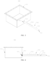
- FIG. 1 is a schematic structural diagram of a vehicle 10 according to an embodiment of the present application.
- the vehicle 10 may be a fuel-powered vehicle, a gas-powered vehicle or a new energy vehicle.
- the new energy vehicle may be a battery electric vehicle, a hybrid vehicle or an extended-range vehicle, or the like.
- a motor 20, a controller 30 and a battery 40 may be provided inside the vehicle 10, and the controller 30 is configured to control the battery 40 to supply power to the motor 20, for example, the battery 40 is provided at the bottom or head of the vehicle 10.
- the battery 40 may be configured to supply power to the vehicle 10.
- the battery 40 may be configured as an operation power source of the vehicle 10 and is configured to an electrical system of the vehicle 10, for example, for a working power demand of the vehicle 10 during startup, navigation and running.
- the vehicle 10 is powered by a battery 40 as shown in FIG. 2 .
- the battery 40 may include a box assembly 400 and a battery cell 600, the battery assembly 400 includes a box 410, and the battery cell 600 provided in the box 410.
- box assembly 400 provided by an embodiment of the present application may include the foregoing box 410, a fire-fighting apparatus 500 and a pressure relief mechanism 700.
- the fire-fighting apparatus 500 is provided outside the box 410, and the fire-fighting apparatus 500 includes a pipe 510, and an air inlet end 511 of the pipe 510 is connected to the box 410, for example, the air inlet end 511 is connected to the box 410 through the pressure relief mechanism 700.
- the pressure relief mechanism 700 may be provided on the box 410, or provided on the fire-fighting apparatus 500, for example, provided on the pipe 510 of the fire-fighting apparatus 500.
- the gas release mechanism 520 is configured to be connected to the pipe 510, and the gas release mechanism 520 is configured to release a fire-fighting gas into the pipe 510 when thermal runaway occurs in the battery 40.
- a blocking structure 530 is provided in the pipe 510, and is configured to block the fire-fighting gas and combustible gas and change a flow direction, so that the fire-fighting gas and combustible gas are capable of being mixed before being discharged from the pipe 510.
- a blocking structure 530 allows the combustible gas and the fire-fighting gas to be mixed up in the pipe 510, to reduce the concentration of the combustible gas in the pipe 510, so that the mixed gas discharged from the air outlet end 512 of the pipe 510 is not easy to catch fire and explode when it comes into contact with air.
- the fire-fighting gas is also beneficial for lowering a temperature of the combustible gas, thereby further preventing the occurrence of open flames.
- the air inlet end 511 of the pipe 510 may be directly connected to the box 410 of the battery 40, or indirectly connected thereto through an intermediate member, which is not limited in the present application.
- the fire-fighting gas may be any suitable gas as long as it can have a fire prevention effect after being mixed with the combustible gas.
- the fire-fighting gas may include a non-combustible gas such as an inert gas, carbon dioxide gas, heptafluoropropane gas, sulfur hexafluoride, or the like.
- a non-combustible gas such as an inert gas, carbon dioxide gas, heptafluoropropane gas, sulfur hexafluoride, or the like.
- the blocking structure 530 may be configured to provide a flow path of at least part of a gas in the pipe 510 a meandering shape, that is, through the blocking structure 530, at least part of the mixed gas of the fire-fighting gas and the combustible gas would travel in the pipe 510 along a curved path toward the air outlet end 512 of the pipe 510.
- the advantages of the traveling of the gas in the pipe 510 in a meandering manner are: on one hand, a mixing path of the fire-fighting gas and the combustible gas can be extended, and a mixing time of the fire-fighting gas and the combustible gas can be increased, thereby improving the mixing effect of the two; on another hand, traveling in a meandering manner intensifies the colliding and mixing of the fire-fighting gas and the combustible gas, thereby improving the mixing effect of the two and reducing the possibility of the occurrence of fire due to the excessive-high local concentration of the combustible gas discharged from the pipe 510.
- the flow path of the gas in "the meandering shape” may mean that the flow path of the gas in the pipe 510 is any suitable curved shape such as an S-shape, a spiral shape, a sine/cosine wave, or the like.
- a projection of the blocking structure 530 in an extension direction of the pipe covers a projection of a cavity (that is, an inner passage) of the pipe 510 in the extension direction of the pipe 510.
- a projection of a cavity that is, an inner passage
- the blocking structure 530 may have any appropriate structure as long as it can provide a flow path of the gas a meandering shape when the gas flows through the blocking structure 530.
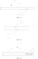
- a blocking structure 530 includes a plurality of baffle plates 531, and the plurality of baffle plates 531 are arranged at intervals in an extension direction of a pipe 510.
- the baffle plate 531 is provided with an opening 800 for a gas to pass through, or the baffle plate 531 and an inner wall of the pipe 510 are enclosed to form an opening 800 for a gas to pass through.
- the projections of two adjacent openings 800 in the extension direction of the pipe 510 are disposed to be misaligned, so that when the gas flows through the plurality of baffle plates 531, a flow path of the gas is a meandering path.
- the baffle plate 531 can not only mix the gases, but also prevent a high-temperature particle entering the pipe 510 from the box 410 from flowing out of the pipe 510, thereby avoiding risks that may be caused by the outflow of the high-temperature particle, such as a fire.
- the plurality of baffle plates 531 may be integrally connected through a first connecting rod 533 to facilitate the connection between the plurality of baffle plates 531 and the pipe 510.
- a first connecting rod 533 to facilitate the connection between the plurality of baffle plates 531 and the pipe 510.
- the plurality of baffle plates 531 when installed, may only one of the baffle plates 531 being connected to the inner wall of the pipe 510 is already sufficient, and it is not necessary to connect each baffle plate 531 to the inner wall of the pipe 510.
- a plurality of baffle plates 531 at least include a pair of arc-shaped plates, and concave surfaces 5311 of the pair of arc-shaped plates are disposed opposite to each other.
- the installation position of the gas release mechanism 520 on the pipe 510 may be located between the plurality of blocking structures 530, or between the plurality of baffle plates 531.
- the gas release mechanism 520 may be disposed either outside or inside the pipe 510.
- a gas release mechanism 520 may be disposed outside a pipe 510.
- a through hole 513 is provided on a wall of the pipe 510, and the gas release mechanism 520 is connected to the through hole 513 to release a fire-fighting gas into the pipe 510 through the through hole 513.
- the gas release mechanism 520 is disposed outside the pipe 510, so that a size of the gas release mechanism 520 may not be limited by a size of a cavity of the pipe 510, which is beneficial for the installation of the gas release mechanism 520 that has a larger gas production.
- the number of through holes 513 is multiple, and the multiple through holes 513 are arranged at intervals in an extension direction of the pipe 510.
- the multiple through holes 513 may ensure a rapid release of a sufficient amount of fire-fighting gas, thus ensuring the reliability of fire prevention.
- each through hole 513 may correspond to one gas release mechanism 520, or multiple through holes 513 may correspond to one gas release mechanism 520.
- only one gas release mechanism 520 may be provided, and the gas release mechanism 520 is connected to the pipe 510 through the multiple through holes 513.
- a plurality of gas release mechanisms 520 may be provided, and each gas release mechanism 520 may correspond to one, two or any suitable number of through holes 513.
- the foregoing through hole 513 may be configured as a threaded through hole 513 to form a threaded connection with the gas release mechanism 520, so as to ensure the reliability of the installation of the gas release mechanism 520 on the pipe 510 and the sealing connection between the gas release mechanism 520 and the pipe 510.
- a sealant (a sealing silicone rubber) may be provided at a connection position between the gas release mechanism 520 and the pipe 510 to further ensure the sealing performance of the connection between the gas release mechanism 520 and the inner wall of the through hole 513.
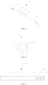
- the air inlet end 511 of the pipe 510 is provided with a flange 514.
- a fire-fighting apparatus 500 also includes a gas collection device 540, and the gas collection device 540 is hermetically connected to the air outlet end 512 of the pipe 510, and is configured to collect a gas discharged from the air outlet end, so as to prevent the mixed gas from being directly discharged to the external environment and polluting the environment.
- the gas release mechanism 520 may have any suitable structure and shape. As shown in FIG. 22 to FIG. 25 , the gas release mechanism 520 may include a fire-fighting medium 521 (a fire-fighting agent), a housing 522, and a closure member 523.
- the fire-fighting medium 521 may be a fire-fighting gas or a fire-fighting solid or a fire-fighting liquid capable of generating the fire-fighting gas.
- the housing 522 is configured to accommodate the fire-fighting medium 521, and the housing 522 is connected to the through hole 513, and is provided with an air outlet hole 5221.
- the closure member 523 closes the air outlet hole 5221.
- the closure member 523 releases the closure of the air outlet hole 5221, that is, opens the air outlet hole 5221, so that the fire-fighting gas in the housing 522 can enter the pipe 510 through the air outlet hole 5221 to realize mixing with the combustible gas.
- the fire-fighting medium 521 is a fire-fighting solid or a fire-fighting liquid
- the gas release mechanism 520 further includes a trigger 524
- the trigger 524 is configured to trigger the fire-fighting solid or fire-fighting liquid to generate a fire-fighting gas when thermal runaway occurs in the battery.
- the closure member 523 is configured to be able to open the air outlet hole 5221 when the air pressure in the housing 522 reaches a first threshold, so as to release the fire-fighting gas.
- first threshold may be any appropriate value, and the specific parameter may be determined according to the actual situation.
- a controller may be used to transmit a trigger signal to the trigger 524.
- the controller configured to transmit the trigger signal to the trigger 524 may be a controller of the battery 40 or a controller self-contained by the fire-fighting apparatus 500.
- the controller may detect the thermal runaway of the battery 40 through, for example, a temperature sensor or a smoke sensor, or the like. When the thermal runaway occurs in the battery 40, the temperature sensor or the smoke sensor may transmit the detected result to the controller, and then the controller controls the trigger 524 to work according to the detection structure of the temperature sensor or the smoke sensor.
- the gas release mechanism 520 also includes a lead 525, one end of the lead 525 is electrically connected to the trigger 524, and another end thereof may pass through the housing 522 and be electrically connected to an external controller.
- the controller sends, to the trigger 524 through the lead 525, a trigger signal used for triggering the fire-fighting medium 521 to generate the gas.
- the controller may communicate wirelessly with the trigger 524.
- the housing 522 is also provided with a sealing valve 526 configured to input the fire-fighting liquid or the fire-fighting gas.
- the fire-fighting medium may be selected from one or more kinds of the fire-fighting solid, the fire-fighting liquid and the fire-fighting gas, which is not limited in the present application.
- the fire-fighting solid such as a solid aerosol
- the fire-fighting solid is adjustable both in size and shape, and also has a large gas production per unit volume, which can maximize the space utilization.
- the fire-fighting solid is triggered to generate gas when the thermal runway occurs, forming an aerosol form.
- the fire-fighting medium 521 may be selected from a substance that can generate a free radical scavenger or contain a free radical scavenges
- the free radical scavenger also known as a free radical capture agent
- the free radical scavenger is a substance that can react with an active free radical to form a stable free radical or a stable molecule.
- DPPH 2,2-diphenyl-1-trinitrophenylhydrazine
- p-benzoquinone p-benzoquinone
- tetramethylbenzoquinone 2-methyl-2-nitrosomethane
- phenyl-N-tert-butyl nitrone etc. can react with the free radical to form a stable free radical.
- the fire-fighting medium 521 is solid potassium nitrate, which is decomposed by heat to form a free radical scavenger.
- the free radical scavenger is easier to combine with oxygen (including oxygen in the gas discharged from the pressure relief mechanism 700, oxygen in the pipe 510, and oxygen in the external environment) or a substance discharged from the pressure relief mechanism 700 that is easy to combine with oxygen to generate a high-temperature combustible substance, and the substance combined by the free radical scavenger is a combustible free radical.
- the free radical scavenger can consume a combustible free radical generated after the thermal runaway of the battery 40, which reduces the possibility of combining and combusting of the combustible free radical and oxygen, and reduces the possibility of generating open flames by tackling the root causes.
- the free radical scavenger is combined with the combustible free radical, and an inert gas such as nitrogen can be produced, the inert gas is difficult to chemically react with oxygen or other substances, and occupies the internal space of the pipe 510, so as to reduce the oxygen content in the pipe 510, dilute the gas in the pipe 510 and reduce the concentration of combustible substances and oxygen in the pipe 510.
- the fire-fighting liquid may be liquid sulfur hexafluoride or hexafluoropropane, and the gasification thereof can achieve the effect of lowering the temperature. Since sulfur hexafluoride or hexafluoropropane has strong electrical insulation characteristics, it can dilute the combustible gas while protecting the high voltage circuit of the battery 40.
- a method for producing a battery includes the following steps.
- the pipe 510, the gas release mechanism 520, and the blocking structure 530 may be the foregoing pipe 510, the gas release mechanism 520, and the blocking structure 530.
Landscapes
- Chemical & Material Sciences (AREA)
- Chemical Kinetics & Catalysis (AREA)
- Electrochemistry (AREA)
- General Chemical & Material Sciences (AREA)
- Health & Medical Sciences (AREA)
- Public Health (AREA)
- Business, Economics & Management (AREA)
- Emergency Management (AREA)
- Engineering & Computer Science (AREA)
- Manufacturing & Machinery (AREA)
- Battery Mounting, Suspending (AREA)
- Gas Exhaust Devices For Batteries (AREA)
Claims (15)
- Appareil de lutte contre l'incendie (500) configuré pour une batterie (40), comprenant :un tuyau (510) comportant une extrémité d'entrée d'air (511) et une extrémité de sortie d'air (512), l'extrémité d'entrée d'air (511) étant configurée pour être raccordée à un boîtier (410) de la batterie (40), de telle sorte qu'un gaz combustible généré lors d'un emballement thermique dans la batterie (40) puisse entrer dans le tuyau (510) depuis le boîtier (410) par l'extrémité d'entrée d'air (511) et soit évacué du tuyau (510) par l'extrémité de sortie d'air (512) ; etun mécanisme de libération de gaz (520), configuré pour être raccordé au tuyau (510), le mécanisme de libération de gaz (520) étant configuré pour libérer un gaz de lutte contre l'incendie dans le tuyau (510) lors d'un emballement thermique dans la batterie ;une structure de blocage (530) étant située dans le tuyau (510), la structure de blocage (530) étant configurée pour bloquer le gaz combustible et le gaz de lutte contre l'incendie et modifier une direction d'écoulement, de telle sorte que le gaz combustible et le gaz de lutte contre l'incendie puissent se mélanger avant d'être évacués du tuyau (510) ;le mécanisme de libération de gaz (520) étant installé sur le tuyau (510) ;la structure de blocage (530) comprenant une pluralité de déflecteurs (531), la pluralité de déflecteurs (531) étant agencés à intervalles dans une direction d'extension du tuyau (530), et le déflecteur (531) étant muni d'une ouverture (800) pour le passage d'un gaz ou bien le déflecteur (531) et une paroi intérieure du tuyau (510) étant enfermés pour former une ouverture (800) pour le passage d'un gaz, des protubérances de deux ouvertures (800) adjacentes dans la direction d'extension du tuyau (510) étant disposées de manière à être désalignées ;une longueur du tuyau (510) allant de 50 à 200 cm.
- Appareil de lutte contre l'incendie (500) selon la revendication 1, dans lequel la structure de blocage (530) est configurée pour faire en sorte qu'une trajectoire d'écoulement d'au moins une partie d'un gaz dans le tuyau suive une forme sinueuse.
- Appareil de lutte contre l'incendie (500) selon la revendication 2, dans lequel une protubérance de la structure de blocage (530) dans une direction d'extension du tuyau (510) couvre une protubérance d'une cavité du tuyau (510) dans la direction d'extension du tuyau (510).
- Appareil de lutte contre l'incendie (500) selon l'une quelconque des revendications 1 à 3, dans lequel la pluralité de déflecteurs (531) comprennent au moins une paire de plaques arquées, des surfaces concaves (5311) de la paire de plaques arquées étant disposées à l'opposé l'une de l'autre.
- Appareil de lutte contre l'incendie (500) selon l'une quelconque des revendications 1 à 4, dans lequel la structure de blocage (530) comprend une lame en spirale (532), une ligne centrale de la lame en spirale (532) coïncidant avec un axe central du tuyau (510) ou étant parallèle à celui-ci, et/ou dans lequel la structure de blocage (530) comprend une pluralité de lames en spirale (532), la pluralité de lames en spirale (532) étant agencées dans une direction d'extension du tuyau (510), et les directions de rotation de deux lames en spirale (532) adjacentes étant opposées.
- Appareil de lutte contre l'incendie (500) selon la revendication 1, dans lequel une position d'installation du mécanisme de libération de gaz (520) est plus proche de l'extrémité de l'entrée d'air (511) que de la structure de blocage (530).
- Appareil de lutte contre l'incendie (500) selon la revendication 1 ou 6, dans lequel le mécanisme de libération de gaz (520) est situé à l'extérieur du tuyau (510), un trou traversant (513) est situé sur une paroi du tuyau (510), et le mécanisme de libération de gaz (520) est raccordé au trou de passage (513) pour libérer le gaz de lutte contre l'incendie dans le tuyau (510) par le trou traversant (513).
- Appareil de lutte contre l'incendie (500) selon la revendication 7, dans lequel le trou traversant (513) est multiple en quantité, et de multiples trous traversants (513) sont agencés à intervalles dans une direction d'extension du tuyau (510).
- Appareil de lutte contre l'incendie (500) selon la revendication 7 ou 8, dans lequel le mécanisme de libération de gaz (520) comprend :un milieu de lutte contre l'incendie (521), le milieu de lutte contre l'incendie (521) étant le gaz de lutte contre l'incendie ou bien un solide de lutte contre l'incendie ou un liquide de lutte contre l'incendie capable de générer le gaz de lutte contre l'incendie ;un corps (522), configuré pour recevoir le milieu de lutte contre l'incendie (521), le corps (522) étant raccordé au trou traversant (513) et muni d'un trou de sortie d'air (5221) ; etun élément de fermeture (523), configuré pour fermer le trou de sortie d'air (5221), l'élément de fermeture (523) étant configuré pour pouvoir libérer une fermeture du trou de sortie d'air (5221) lors d'un emballement thermique dans la batterie (40), de telle sorte que le gaz de lutte contre l'incendie pénètre dans le tuyau (510) par le trou de sortie d'air (5221).
- Appareil de lutte contre l'incendie (500) selon la revendication 9, dans lequel le milieu de lutte contre l'incendie (521) est le solide de lutte contre l'incendie ou le liquide de lutte contre l'incendie, et le mécanisme de libération de gaz (520) comprend en outre un déclencheur (524), le déclencheur (524) étant configuré pour déclencher le solide de lutte contre l'incendie ou le liquide de lutte contre l'incendie lors d'un emballement thermique dans la batterie (40) pour générer le gaz de lutte contre l'incendie, et l'élément de fermeture (523) étant configuré pour pouvoir ouvrir le trou de sortie d'air (5221) lorsqu'une pression d'air dans le corps (522) atteint un premier seuil pour libérer le gaz de lutte contre l'incendie ; ou
le milieu de lutte contre l'incendie (521) est soit le liquide de lutte contre l'incendie capable de générer le gaz de lutte contre l'incendie, soit le gaz de lutte contre l'incendie, et le liquide de lutte contre l'incendie ou le gaz de lutte contre l'incendie est encapsulé dans le corps (522), et lorsque le trou de sortie d'air (5221) est fermé par l'élément de fermeture (523) une pression dans le corps (522) est supérieure à une pression dans le tuyau (510), l'élément de fermeture (523) étant une soupape. - Appareil de lutte contre l'incendie selon l'une quelconque des revendications 1 à 10, l'appareil de lutte contre l'incendie comprenant en outre un dispositif de collecte de gaz, le dispositif de collecte de gaz étant raccordé hermétiquement à l'extrémité de sortie d'air pour collecter un gaz évacué par l'extrémité de sortie d'air.
- Ensemble boîtier, comprenant :un boîtier, configuré pour recevoir un élément de batterie ;l'appareil de lutte contre l'incendie selon l'une quelconque des revendications 1 à 11, l'appareil de lutte contre l'incendie étant situé à l'extérieur du boîtier, et l'extrémité d'entrée d'air de l'appareil de lutte contre l'incendie étant raccordée au boîtier ; etun mécanisme de décompression, configuré pour être actionné lorsqu'une pression ou une température de l'air dans le boîtier atteint un second seuil, de telle sorte qu'un gaz combustible présent dans le boîtier puisse pénétrer dans le tuyau par l'extrémité d'entrée d'air.
- Ensemble boîtier selon la revendication 12, dans lequel le mécanisme de décompression est situé sur le boîtier, et l'extrémité d'entrée d'air est recouverte sur le mécanisme de décompression.
- Batterie, comprenant :l'ensemble boîtier selon la revendication 12 ou 13 ; etun élément de batterie, situé dans le boîtier.
- Appareil de consommation d'énergie, comprenant la batterie selon la revendication 14.
Priority Applications (1)
| Application Number | Priority Date | Filing Date | Title |
|---|---|---|---|
| EP23170778.7A EP4228046B1 (fr) | 2020-11-17 | 2020-11-17 | Appareil de lutte contre l'incendie, ensemble boîtier, batterie, appareil de consommation d'énergie et procédé de préparation de batterie |
Applications Claiming Priority (3)
| Application Number | Priority Date | Filing Date | Title |
|---|---|---|---|
| EP23170778.7A EP4228046B1 (fr) | 2020-11-17 | 2020-11-17 | Appareil de lutte contre l'incendie, ensemble boîtier, batterie, appareil de consommation d'énergie et procédé de préparation de batterie |
| PCT/CN2020/129433 WO2022104539A1 (fr) | 2020-11-17 | 2020-11-17 | Dispositif de prévention d'incendie, ensemble boîte, batterie, dispositif électrique et procédé de production de batterie |
| EP20939484.0A EP4044319B1 (fr) | 2020-11-17 | 2020-11-17 | Dispositif de prévention d'incendie, ensemble boîte, batterie, dispositif électrique et procédé de production de batterie |
Related Parent Applications (2)
| Application Number | Title | Priority Date | Filing Date |
|---|---|---|---|
| EP20939484.0A Division EP4044319B1 (fr) | 2020-11-17 | 2020-11-17 | Dispositif de prévention d'incendie, ensemble boîte, batterie, dispositif électrique et procédé de production de batterie |
| EP20939484.0A Division-Into EP4044319B1 (fr) | 2020-11-17 | 2020-11-17 | Dispositif de prévention d'incendie, ensemble boîte, batterie, dispositif électrique et procédé de production de batterie |
Publications (2)
| Publication Number | Publication Date |
|---|---|
| EP4228046A1 EP4228046A1 (fr) | 2023-08-16 |
| EP4228046B1 true EP4228046B1 (fr) | 2024-07-03 |
Family
ID=81707941
Family Applications (4)
| Application Number | Title | Priority Date | Filing Date |
|---|---|---|---|
| EP23170786.0A Active EP4239750B1 (fr) | 2020-11-17 | 2020-11-17 | Appareil de lutte contre l'incendie, ensemble boîtier, batterie, appareil de consommation d'énergie et procédé de préparation de batterie |
| EP23170788.6A Active EP4239751B1 (fr) | 2020-11-17 | 2020-11-17 | Appareil de lutte contre l'incendie, ensemble boîtier, batterie, appareil de consommation d'énergie et procédé de préparation de batterie |
| EP20939484.0A Active EP4044319B1 (fr) | 2020-11-17 | 2020-11-17 | Dispositif de prévention d'incendie, ensemble boîte, batterie, dispositif électrique et procédé de production de batterie |
| EP23170778.7A Active EP4228046B1 (fr) | 2020-11-17 | 2020-11-17 | Appareil de lutte contre l'incendie, ensemble boîtier, batterie, appareil de consommation d'énergie et procédé de préparation de batterie |
Family Applications Before (3)
| Application Number | Title | Priority Date | Filing Date |
|---|---|---|---|
| EP23170786.0A Active EP4239750B1 (fr) | 2020-11-17 | 2020-11-17 | Appareil de lutte contre l'incendie, ensemble boîtier, batterie, appareil de consommation d'énergie et procédé de préparation de batterie |
| EP23170788.6A Active EP4239751B1 (fr) | 2020-11-17 | 2020-11-17 | Appareil de lutte contre l'incendie, ensemble boîtier, batterie, appareil de consommation d'énergie et procédé de préparation de batterie |
| EP20939484.0A Active EP4044319B1 (fr) | 2020-11-17 | 2020-11-17 | Dispositif de prévention d'incendie, ensemble boîte, batterie, dispositif électrique et procédé de production de batterie |
Country Status (6)
| Country | Link |
|---|---|
| US (2) | US11826593B2 (fr) |
| EP (4) | EP4239750B1 (fr) |
| JP (2) | JP7483920B2 (fr) |
| KR (2) | KR102625181B1 (fr) |
| HU (3) | HUE069147T2 (fr) |
| WO (1) | WO2022104539A1 (fr) |
Families Citing this family (7)
| Publication number | Priority date | Publication date | Assignee | Title |
|---|---|---|---|---|
| AT526457B1 (de) * | 2022-08-25 | 2025-04-15 | Siemens Mobility Austria Gmbh | Akkumulatorengehäuse für ein Schienenfahrzeug |
| CN117645057A (zh) * | 2022-09-02 | 2024-03-05 | 上海火亮新能源科技有限公司 | 一种基于电池包实时监测的动力电池包转运装置 |
| FR3149388A1 (fr) | 2023-06-05 | 2024-12-06 | Gesop | Dispositif de securite incendie pour la recharge d’une batterie electrique |
| CN117007354A (zh) * | 2023-06-14 | 2023-11-07 | 吉林大学 | 一种锂离子电池热失控后可沉积颗粒物收集装置 |
| CN117244196B (zh) * | 2023-11-17 | 2024-02-20 | 杭州高特电子设备股份有限公司 | 储能电池的消防控制方法、装置、计算机设备及存储介质 |
| WO2025139921A1 (fr) * | 2023-12-28 | 2025-07-03 | 双澳储能科技(西安)有限公司 | Appareil et procédé de traitement de gaz d'emballement thermique, procédé de test d'étanchéité à l'air pour appareil de traitement de gaz d'emballement thermique, et dispositif de stockage d'énergie |
| KR20250125710A (ko) * | 2024-02-15 | 2025-08-22 | 주식회사 엘지에너지솔루션 | 배터리 팩 및 이를 포함하는 자동차 |
Family Cites Families (34)
| Publication number | Priority date | Publication date | Assignee | Title |
|---|---|---|---|---|
| JPS6037169U (ja) | 1983-08-19 | 1985-03-14 | 日本電池株式会社 | 蓄電池装置 |
| JP3670868B2 (ja) * | 1998-10-30 | 2005-07-13 | 三洋電機株式会社 | 組電池 |
| US8323812B2 (en) | 2006-10-13 | 2012-12-04 | Panasonic Corporation | Battery pack, battery-mounted device and connection structure for battery pack |
| JP2008251308A (ja) | 2007-03-30 | 2008-10-16 | Toyota Motor Corp | 蓄電装置及び車両 |
| DE102009000660A1 (de) * | 2009-02-06 | 2010-08-12 | Robert Bosch Gmbh | Batteriemodul |
| JP5341156B2 (ja) * | 2011-09-06 | 2013-11-13 | 三洋電機株式会社 | 電源装置 |
| KR101424704B1 (ko) * | 2011-09-08 | 2014-07-31 | 주식회사 엘지화학 | 배터리 팩 화재진압 장치 |
| KR101294169B1 (ko) * | 2011-09-26 | 2013-08-08 | 기아자동차주식회사 | 전기자동차용 배터리팩 화재 방지기구 |
| JP5974520B2 (ja) | 2012-02-08 | 2016-08-23 | 株式会社Gsユアサ | 蓄電デバイス及び蓄電モジュール |
| DE102012019676B4 (de) * | 2012-10-05 | 2017-10-26 | Stöbich Technology Gmbh | Akku-Transportbehälter, Akku-Transportgebinde und Akku-Transportvorrichtung |
| JP6390062B2 (ja) * | 2014-12-08 | 2018-09-19 | 三菱重工業株式会社 | 電池モジュール |
| KR102358433B1 (ko) * | 2015-04-17 | 2022-02-04 | 삼성에스디아이 주식회사 | 배터리 팩 |
| CN205508970U (zh) | 2016-03-18 | 2016-08-24 | 山东泰汽新能源工程研究院有限公司 | 一种新型高安全标准的锂离子电池包被动消防灭火结构 |
| CN107303471A (zh) * | 2016-04-22 | 2017-10-31 | 湖北强达环保科技股份有限公司 | 一种管道混合器 |
| JP6821391B2 (ja) * | 2016-10-26 | 2021-01-27 | 三洋電機株式会社 | 電源装置及びこれを用いる車両並びに蓄電装置 |
| JP6988307B2 (ja) | 2017-09-22 | 2022-01-05 | 日産自動車株式会社 | 電池パックシステム |
| JP6988308B2 (ja) | 2017-09-22 | 2022-01-05 | 日産自動車株式会社 | 電池パックシステム |
| CN207409561U (zh) | 2017-11-02 | 2018-05-25 | 宁德时代新能源科技股份有限公司 | 电池箱和电池包 |
| WO2019176415A1 (fr) * | 2018-03-12 | 2019-09-19 | パナソニックIpマネジメント株式会社 | Conduit d'évacuation de bloc-batterie et bloc-batterie |
| CN208548429U (zh) | 2018-07-27 | 2019-02-26 | 清华大学 | 锂离子电池 |
| CN109103391B (zh) * | 2018-07-27 | 2024-01-02 | 清华大学 | 锂离子电池系统及耗能产品 |
| CN108879001A (zh) | 2018-07-27 | 2018-11-23 | 清华大学 | 锂离子电池 |
| CN109103392B (zh) * | 2018-07-27 | 2024-01-05 | 清华大学 | 锂离子电池系统及耗能产品 |
| CN109103388B (zh) * | 2018-07-27 | 2024-01-05 | 清华大学 | 锂离子电池系统及耗能产品 |
| JP7325063B2 (ja) | 2018-08-23 | 2023-08-14 | パナソニックIpマネジメント株式会社 | 電池モジュール |
| JP7070448B2 (ja) * | 2019-01-21 | 2022-05-18 | トヨタ自動車株式会社 | 排煙ダクト |
| JP7401467B2 (ja) * | 2019-01-25 | 2023-12-19 | パナソニックエナジー株式会社 | パック電池 |
| KR102400818B1 (ko) * | 2019-03-06 | 2022-05-20 | 주식회사 엘지에너지솔루션 | 열폭주 현상 발생 시 모듈 내부로 공기 유입을 막을 수 있는 구조를 갖는 배터리 모듈 및 이를 포함하는 배터리 팩 |
| DE102019114047A1 (de) * | 2019-05-27 | 2020-12-03 | Bayerische Motoren Werke Aktiengesellschaft | Speichermodul mit einer Entgasungsleitung |
| CN110459719B (zh) | 2019-08-29 | 2024-11-12 | 清华大学 | 电池包烟气流道系统及电池包 |
| JP2021150127A (ja) * | 2020-03-18 | 2021-09-27 | 三菱電機株式会社 | 消炎バリア構造 |
| CN211789233U (zh) * | 2020-05-26 | 2020-10-27 | 烟台创为新能源科技股份有限公司 | 一种用于电池包的安全排气装置 |
| KR20220007811A (ko) * | 2020-07-10 | 2022-01-19 | 현대자동차주식회사 | 차량용 배터리 팩 및 이를 포함하는 차량 |
| KR102670158B1 (ko) * | 2020-08-27 | 2024-05-29 | 얀타이 추앙웨이 뉴 에너지 테크놀로지 컴퍼니., 리미티드. | 배터리 팩의 배기 필터 시스템 |
-
2020
- 2020-11-17 KR KR1020227033639A patent/KR102625181B1/ko active Active
- 2020-11-17 JP JP2022557943A patent/JP7483920B2/ja active Active
- 2020-11-17 HU HUE23170786A patent/HUE069147T2/hu unknown
- 2020-11-17 KR KR1020247000935A patent/KR20240011236A/ko active Pending
- 2020-11-17 EP EP23170786.0A patent/EP4239750B1/fr active Active
- 2020-11-17 EP EP23170788.6A patent/EP4239751B1/fr active Active
- 2020-11-17 HU HUE23170788A patent/HUE069148T2/hu unknown
- 2020-11-17 HU HUE20939484A patent/HUE062250T2/hu unknown
- 2020-11-17 EP EP20939484.0A patent/EP4044319B1/fr active Active
- 2020-11-17 EP EP23170778.7A patent/EP4228046B1/fr active Active
- 2020-11-17 WO PCT/CN2020/129433 patent/WO2022104539A1/fr not_active Ceased
-
2022
- 2022-04-12 US US17/718,832 patent/US11826593B2/en active Active
-
2023
- 2023-10-13 US US18/379,714 patent/US12121763B2/en active Active
-
2024
- 2024-04-26 JP JP2024072636A patent/JP7791240B2/ja active Active
Also Published As
| Publication number | Publication date |
|---|---|
| EP4239750A1 (fr) | 2023-09-06 |
| EP4044319A1 (fr) | 2022-08-17 |
| HUE069147T2 (hu) | 2025-02-28 |
| US12121763B2 (en) | 2024-10-22 |
| KR102625181B1 (ko) | 2024-01-16 |
| HUE069148T2 (hu) | 2025-02-28 |
| EP4239751B1 (fr) | 2024-09-04 |
| JP2024097832A (ja) | 2024-07-19 |
| JP7483920B2 (ja) | 2024-05-15 |
| JP2023518586A (ja) | 2023-05-02 |
| KR20240011236A (ko) | 2024-01-25 |
| US11826593B2 (en) | 2023-11-28 |
| WO2022104539A1 (fr) | 2022-05-27 |
| JP7791240B2 (ja) | 2025-12-23 |
| HUE062250T2 (hu) | 2023-10-28 |
| EP4044319B1 (fr) | 2023-06-14 |
| US20220233899A1 (en) | 2022-07-28 |
| EP4228046A1 (fr) | 2023-08-16 |
| US20240033549A1 (en) | 2024-02-01 |
| EP4044319A4 (fr) | 2022-08-17 |
| EP4239750B1 (fr) | 2024-09-04 |
| KR20220147657A (ko) | 2022-11-03 |
| EP4239751A1 (fr) | 2023-09-06 |
Similar Documents
| Publication | Publication Date | Title |
|---|---|---|
| EP4228046B1 (fr) | Appareil de lutte contre l'incendie, ensemble boîtier, batterie, appareil de consommation d'énergie et procédé de préparation de batterie | |
| CN112103445B (zh) | 消防装置、箱体组件、电池、用电装置及制备电池的方法 | |
| US20230282918A1 (en) | Box, battery, electrical device and method for manufacturing battery | |
| CN216354617U (zh) | 电池单体、电池以及用电装置 | |
| EP4195367B1 (fr) | Batterie et appareil associé, procédé de production et dispositif de production associé | |
| CN112103444B (zh) | 电池、用电设备及电池的制造方法 | |
| CN117981152A (zh) | 电池、用电设备、制造电池的方法和设备 | |
| CN218569126U (zh) | 电池单体、电池及用电装置 | |
| WO2022205325A1 (fr) | Élément de batterie, batterie, appareil consommateur d'énergie, et procédé et dispositif de fabrication d'élément de batterie | |
| CN220873705U (zh) | 一种电池单体、盖板套件、电池及用电装置 | |
| US20230361415A1 (en) | Battery cell, battery, and electrical device | |
| EP4510299A1 (fr) | Batterie et dispositif électrique | |
| US20240204326A1 (en) | Battery module, battery pack, and electronic device | |
| WO2023097456A1 (fr) | Batterie, dispositif électrique et procédé et dispositif de préparation de batterie | |
| EP4270576B1 (fr) | Batterie, dispositif électrique et procédé et dispositif de préparation de batterie | |
| RU2805991C1 (ru) | Батарея и связанное с ней устройство, способ ее изготовления и устройство для ее изготовления | |
| KR102885437B1 (ko) | 배터리 및 그 제조 방법, 제조 장치와 전기 장치 |
Legal Events
| Date | Code | Title | Description |
|---|---|---|---|
| PUAI | Public reference made under article 153(3) epc to a published international application that has entered the european phase |
Free format text: ORIGINAL CODE: 0009012 |
|
| STAA | Information on the status of an ep patent application or granted ep patent |
Free format text: STATUS: REQUEST FOR EXAMINATION WAS MADE |
|
| 17P | Request for examination filed |
Effective date: 20230428 |
|
| AC | Divisional application: reference to earlier application |
Ref document number: 4044319 Country of ref document: EP Kind code of ref document: P |
|
| AK | Designated contracting states |
Kind code of ref document: A1 Designated state(s): AL AT BE BG CH CY CZ DE DK EE ES FI FR GB GR HR HU IE IS IT LI LT LU LV MC MK MT NL NO PL PT RO RS SE SI SK SM TR |
|
| GRAP | Despatch of communication of intention to grant a patent |
Free format text: ORIGINAL CODE: EPIDOSNIGR1 |
|
| STAA | Information on the status of an ep patent application or granted ep patent |
Free format text: STATUS: GRANT OF PATENT IS INTENDED |
|
| GRAS | Grant fee paid |
Free format text: ORIGINAL CODE: EPIDOSNIGR3 |
|
| INTG | Intention to grant announced |
Effective date: 20240429 |
|
| GRAA | (expected) grant |
Free format text: ORIGINAL CODE: 0009210 |
|
| STAA | Information on the status of an ep patent application or granted ep patent |
Free format text: STATUS: THE PATENT HAS BEEN GRANTED |
|
| AC | Divisional application: reference to earlier application |
Ref document number: 4044319 Country of ref document: EP Kind code of ref document: P |
|
| AK | Designated contracting states |
Kind code of ref document: B1 Designated state(s): AL AT BE BG CH CY CZ DE DK EE ES FI FR GB GR HR HU IE IS IT LI LT LU LV MC MK MT NL NO PL PT RO RS SE SI SK SM TR |
|
| REG | Reference to a national code |
Ref country code: CH Ref legal event code: EP |
|
| REG | Reference to a national code |
Ref country code: DE Ref legal event code: R096 Ref document number: 602020033587 Country of ref document: DE |
|
| REG | Reference to a national code |
Ref country code: LT Ref legal event code: MG9D |
|
| REG | Reference to a national code |
Ref country code: NL Ref legal event code: MP Effective date: 20240703 |
|
| P01 | Opt-out of the competence of the unified patent court (upc) registered |
Free format text: CASE NUMBER: APP_52952/2024 Effective date: 20240923 |
|
| PG25 | Lapsed in a contracting state [announced via postgrant information from national office to epo] |
Ref country code: PT Free format text: LAPSE BECAUSE OF FAILURE TO SUBMIT A TRANSLATION OF THE DESCRIPTION OR TO PAY THE FEE WITHIN THE PRESCRIBED TIME-LIMIT Effective date: 20241104 |
|
| REG | Reference to a national code |
Ref country code: AT Ref legal event code: MK05 Ref document number: 1700778 Country of ref document: AT Kind code of ref document: T Effective date: 20240703 |
|
| PG25 | Lapsed in a contracting state [announced via postgrant information from national office to epo] |
Ref country code: NL Free format text: LAPSE BECAUSE OF FAILURE TO SUBMIT A TRANSLATION OF THE DESCRIPTION OR TO PAY THE FEE WITHIN THE PRESCRIBED TIME-LIMIT Effective date: 20240703 |
|
| PG25 | Lapsed in a contracting state [announced via postgrant information from national office to epo] |
Ref country code: PT Free format text: LAPSE BECAUSE OF FAILURE TO SUBMIT A TRANSLATION OF THE DESCRIPTION OR TO PAY THE FEE WITHIN THE PRESCRIBED TIME-LIMIT Effective date: 20241104 Ref country code: NL Free format text: LAPSE BECAUSE OF FAILURE TO SUBMIT A TRANSLATION OF THE DESCRIPTION OR TO PAY THE FEE WITHIN THE PRESCRIBED TIME-LIMIT Effective date: 20240703 |
|
| PG25 | Lapsed in a contracting state [announced via postgrant information from national office to epo] |
Ref country code: NO Free format text: LAPSE BECAUSE OF FAILURE TO SUBMIT A TRANSLATION OF THE DESCRIPTION OR TO PAY THE FEE WITHIN THE PRESCRIBED TIME-LIMIT Effective date: 20241003 |
|
| PG25 | Lapsed in a contracting state [announced via postgrant information from national office to epo] |
Ref country code: FI Free format text: LAPSE BECAUSE OF FAILURE TO SUBMIT A TRANSLATION OF THE DESCRIPTION OR TO PAY THE FEE WITHIN THE PRESCRIBED TIME-LIMIT Effective date: 20240703 Ref country code: PL Free format text: LAPSE BECAUSE OF FAILURE TO SUBMIT A TRANSLATION OF THE DESCRIPTION OR TO PAY THE FEE WITHIN THE PRESCRIBED TIME-LIMIT Effective date: 20240703 Ref country code: GR Free format text: LAPSE BECAUSE OF FAILURE TO SUBMIT A TRANSLATION OF THE DESCRIPTION OR TO PAY THE FEE WITHIN THE PRESCRIBED TIME-LIMIT Effective date: 20241004 |
|
| PG25 | Lapsed in a contracting state [announced via postgrant information from national office to epo] |
Ref country code: BG Free format text: LAPSE BECAUSE OF FAILURE TO SUBMIT A TRANSLATION OF THE DESCRIPTION OR TO PAY THE FEE WITHIN THE PRESCRIBED TIME-LIMIT Effective date: 20240703 |
|
| PG25 | Lapsed in a contracting state [announced via postgrant information from national office to epo] |
Ref country code: LV Free format text: LAPSE BECAUSE OF FAILURE TO SUBMIT A TRANSLATION OF THE DESCRIPTION OR TO PAY THE FEE WITHIN THE PRESCRIBED TIME-LIMIT Effective date: 20240703 |
|
| PG25 | Lapsed in a contracting state [announced via postgrant information from national office to epo] |
Ref country code: IS Free format text: LAPSE BECAUSE OF FAILURE TO SUBMIT A TRANSLATION OF THE DESCRIPTION OR TO PAY THE FEE WITHIN THE PRESCRIBED TIME-LIMIT Effective date: 20241103 Ref country code: AT Free format text: LAPSE BECAUSE OF FAILURE TO SUBMIT A TRANSLATION OF THE DESCRIPTION OR TO PAY THE FEE WITHIN THE PRESCRIBED TIME-LIMIT Effective date: 20240703 |
|
| PG25 | Lapsed in a contracting state [announced via postgrant information from national office to epo] |
Ref country code: HR Free format text: LAPSE BECAUSE OF FAILURE TO SUBMIT A TRANSLATION OF THE DESCRIPTION OR TO PAY THE FEE WITHIN THE PRESCRIBED TIME-LIMIT Effective date: 20240703 Ref country code: CZ Free format text: LAPSE BECAUSE OF FAILURE TO SUBMIT A TRANSLATION OF THE DESCRIPTION OR TO PAY THE FEE WITHIN THE PRESCRIBED TIME-LIMIT Effective date: 20240703 |
|
| PG25 | Lapsed in a contracting state [announced via postgrant information from national office to epo] |
Ref country code: RS Free format text: LAPSE BECAUSE OF FAILURE TO SUBMIT A TRANSLATION OF THE DESCRIPTION OR TO PAY THE FEE WITHIN THE PRESCRIBED TIME-LIMIT Effective date: 20241003 Ref country code: ES Free format text: LAPSE BECAUSE OF FAILURE TO SUBMIT A TRANSLATION OF THE DESCRIPTION OR TO PAY THE FEE WITHIN THE PRESCRIBED TIME-LIMIT Effective date: 20240703 |
|
| PG25 | Lapsed in a contracting state [announced via postgrant information from national office to epo] |
Ref country code: RS Free format text: LAPSE BECAUSE OF FAILURE TO SUBMIT A TRANSLATION OF THE DESCRIPTION OR TO PAY THE FEE WITHIN THE PRESCRIBED TIME-LIMIT Effective date: 20241003 Ref country code: PL Free format text: LAPSE BECAUSE OF FAILURE TO SUBMIT A TRANSLATION OF THE DESCRIPTION OR TO PAY THE FEE WITHIN THE PRESCRIBED TIME-LIMIT Effective date: 20240703 Ref country code: NO Free format text: LAPSE BECAUSE OF FAILURE TO SUBMIT A TRANSLATION OF THE DESCRIPTION OR TO PAY THE FEE WITHIN THE PRESCRIBED TIME-LIMIT Effective date: 20241003 Ref country code: LV Free format text: LAPSE BECAUSE OF FAILURE TO SUBMIT A TRANSLATION OF THE DESCRIPTION OR TO PAY THE FEE WITHIN THE PRESCRIBED TIME-LIMIT Effective date: 20240703 Ref country code: IS Free format text: LAPSE BECAUSE OF FAILURE TO SUBMIT A TRANSLATION OF THE DESCRIPTION OR TO PAY THE FEE WITHIN THE PRESCRIBED TIME-LIMIT Effective date: 20241103 Ref country code: HR Free format text: LAPSE BECAUSE OF FAILURE TO SUBMIT A TRANSLATION OF THE DESCRIPTION OR TO PAY THE FEE WITHIN THE PRESCRIBED TIME-LIMIT Effective date: 20240703 Ref country code: GR Free format text: LAPSE BECAUSE OF FAILURE TO SUBMIT A TRANSLATION OF THE DESCRIPTION OR TO PAY THE FEE WITHIN THE PRESCRIBED TIME-LIMIT Effective date: 20241004 Ref country code: FI Free format text: LAPSE BECAUSE OF FAILURE TO SUBMIT A TRANSLATION OF THE DESCRIPTION OR TO PAY THE FEE WITHIN THE PRESCRIBED TIME-LIMIT Effective date: 20240703 Ref country code: ES Free format text: LAPSE BECAUSE OF FAILURE TO SUBMIT A TRANSLATION OF THE DESCRIPTION OR TO PAY THE FEE WITHIN THE PRESCRIBED TIME-LIMIT Effective date: 20240703 Ref country code: CZ Free format text: LAPSE BECAUSE OF FAILURE TO SUBMIT A TRANSLATION OF THE DESCRIPTION OR TO PAY THE FEE WITHIN THE PRESCRIBED TIME-LIMIT Effective date: 20240703 Ref country code: BG Free format text: LAPSE BECAUSE OF FAILURE TO SUBMIT A TRANSLATION OF THE DESCRIPTION OR TO PAY THE FEE WITHIN THE PRESCRIBED TIME-LIMIT Effective date: 20240703 Ref country code: AT Free format text: LAPSE BECAUSE OF FAILURE TO SUBMIT A TRANSLATION OF THE DESCRIPTION OR TO PAY THE FEE WITHIN THE PRESCRIBED TIME-LIMIT Effective date: 20240703 |
|
| REG | Reference to a national code |
Ref country code: DE Ref legal event code: R097 Ref document number: 602020033587 Country of ref document: DE |
|
| PG25 | Lapsed in a contracting state [announced via postgrant information from national office to epo] |
Ref country code: DK Free format text: LAPSE BECAUSE OF FAILURE TO SUBMIT A TRANSLATION OF THE DESCRIPTION OR TO PAY THE FEE WITHIN THE PRESCRIBED TIME-LIMIT Effective date: 20240703 Ref country code: SM Free format text: LAPSE BECAUSE OF FAILURE TO SUBMIT A TRANSLATION OF THE DESCRIPTION OR TO PAY THE FEE WITHIN THE PRESCRIBED TIME-LIMIT Effective date: 20240703 Ref country code: RO Free format text: LAPSE BECAUSE OF FAILURE TO SUBMIT A TRANSLATION OF THE DESCRIPTION OR TO PAY THE FEE WITHIN THE PRESCRIBED TIME-LIMIT Effective date: 20240703 |
|
| PG25 | Lapsed in a contracting state [announced via postgrant information from national office to epo] |
Ref country code: EE Free format text: LAPSE BECAUSE OF FAILURE TO SUBMIT A TRANSLATION OF THE DESCRIPTION OR TO PAY THE FEE WITHIN THE PRESCRIBED TIME-LIMIT Effective date: 20240703 |
|
| PG25 | Lapsed in a contracting state [announced via postgrant information from national office to epo] |
Ref country code: IT Free format text: LAPSE BECAUSE OF FAILURE TO SUBMIT A TRANSLATION OF THE DESCRIPTION OR TO PAY THE FEE WITHIN THE PRESCRIBED TIME-LIMIT Effective date: 20240703 Ref country code: SK Free format text: LAPSE BECAUSE OF FAILURE TO SUBMIT A TRANSLATION OF THE DESCRIPTION OR TO PAY THE FEE WITHIN THE PRESCRIBED TIME-LIMIT Effective date: 20240703 |
|
| PLBE | No opposition filed within time limit |
Free format text: ORIGINAL CODE: 0009261 |
|
| STAA | Information on the status of an ep patent application or granted ep patent |
Free format text: STATUS: NO OPPOSITION FILED WITHIN TIME LIMIT |
|
| 26N | No opposition filed |
Effective date: 20250404 |
|
| REG | Reference to a national code |
Ref country code: CH Ref legal event code: PL |
|
| PG25 | Lapsed in a contracting state [announced via postgrant information from national office to epo] |
Ref country code: MC Free format text: LAPSE BECAUSE OF FAILURE TO SUBMIT A TRANSLATION OF THE DESCRIPTION OR TO PAY THE FEE WITHIN THE PRESCRIBED TIME-LIMIT Effective date: 20240703 |
|
| PG25 | Lapsed in a contracting state [announced via postgrant information from national office to epo] |
Ref country code: LU Free format text: LAPSE BECAUSE OF NON-PAYMENT OF DUE FEES Effective date: 20241117 |
|
| REG | Reference to a national code |
Ref country code: CH Ref legal event code: PL |
|
| PG25 | Lapsed in a contracting state [announced via postgrant information from national office to epo] |
Ref country code: CH Free format text: LAPSE BECAUSE OF NON-PAYMENT OF DUE FEES Effective date: 20241130 |
|
| REG | Reference to a national code |
Ref country code: BE Ref legal event code: MM Effective date: 20241130 |
|
| PG25 | Lapsed in a contracting state [announced via postgrant information from national office to epo] |
Ref country code: SE Free format text: LAPSE BECAUSE OF FAILURE TO SUBMIT A TRANSLATION OF THE DESCRIPTION OR TO PAY THE FEE WITHIN THE PRESCRIBED TIME-LIMIT Effective date: 20240703 |
|
| PG25 | Lapsed in a contracting state [announced via postgrant information from national office to epo] |
Ref country code: BE Free format text: LAPSE BECAUSE OF NON-PAYMENT OF DUE FEES Effective date: 20241130 |
|
| PG25 | Lapsed in a contracting state [announced via postgrant information from national office to epo] |
Ref country code: IE Free format text: LAPSE BECAUSE OF NON-PAYMENT OF DUE FEES Effective date: 20241117 |
|
| PGFP | Annual fee paid to national office [announced via postgrant information from national office to epo] |
Ref country code: DE Payment date: 20251124 Year of fee payment: 6 |
|
| PGFP | Annual fee paid to national office [announced via postgrant information from national office to epo] |
Ref country code: GB Payment date: 20251126 Year of fee payment: 6 |
|
| PGFP | Annual fee paid to national office [announced via postgrant information from national office to epo] |
Ref country code: FR Payment date: 20251128 Year of fee payment: 6 |
|
| PG25 | Lapsed in a contracting state [announced via postgrant information from national office to epo] |
Ref country code: HU Free format text: LAPSE BECAUSE OF FAILURE TO SUBMIT A TRANSLATION OF THE DESCRIPTION OR TO PAY THE FEE WITHIN THE PRESCRIBED TIME-LIMIT; INVALID AB INITIO Effective date: 20201117 |
|
| PG25 | Lapsed in a contracting state [announced via postgrant information from national office to epo] |
Ref country code: CY Free format text: LAPSE BECAUSE OF FAILURE TO SUBMIT A TRANSLATION OF THE DESCRIPTION OR TO PAY THE FEE WITHIN THE PRESCRIBED TIME-LIMIT; INVALID AB INITIO Effective date: 20201117 |