EP4228115B1 - Système de gestion d'énergie intelligent (iems) et profil d'équilibre - Google Patents
Système de gestion d'énergie intelligent (iems) et profil d'équilibre Download PDFInfo
- Publication number
- EP4228115B1 EP4228115B1 EP22156347.1A EP22156347A EP4228115B1 EP 4228115 B1 EP4228115 B1 EP 4228115B1 EP 22156347 A EP22156347 A EP 22156347A EP 4228115 B1 EP4228115 B1 EP 4228115B1
- Authority
- EP
- European Patent Office
- Prior art keywords
- vessel
- devices
- previous
- redundancy
- efficiency
- Prior art date
- Legal status (The legal status is an assumption and is not a legal conclusion. Google has not performed a legal analysis and makes no representation as to the accuracy of the status listed.)
- Active
Links
Images


Classifications
-
- H—ELECTRICITY
- H02—GENERATION; CONVERSION OR DISTRIBUTION OF ELECTRIC POWER
- H02J—ELECTRIC POWER NETWORKS; CIRCUIT ARRANGEMENTS OR SYSTEMS FOR SUPPLYING OR DISTRIBUTING ELECTRIC POWER; SYSTEMS FOR STORING ELECTRIC ENERGY
- H02J3/00—Circuit arrangements for AC mains or AC distribution networks
-
- H—ELECTRICITY
- H02—GENERATION; CONVERSION OR DISTRIBUTION OF ELECTRIC POWER
- H02J—ELECTRIC POWER NETWORKS; CIRCUIT ARRANGEMENTS OR SYSTEMS FOR SUPPLYING OR DISTRIBUTING ELECTRIC POWER; SYSTEMS FOR STORING ELECTRIC ENERGY
- H02J3/00—Circuit arrangements for AC mains or AC distribution networks
- H02J3/12—Arrangements for adjusting voltage in AC networks by changing a characteristic of the network load
- H02J3/14—Arrangements for adjusting voltage in AC networks by changing a characteristic of the network load by switching loads on to, or off from, the networks, e.g. progressively balanced loading
-
- H—ELECTRICITY
- H02—GENERATION; CONVERSION OR DISTRIBUTION OF ELECTRIC POWER
- H02J—ELECTRIC POWER NETWORKS; CIRCUIT ARRANGEMENTS OR SYSTEMS FOR SUPPLYING OR DISTRIBUTING ELECTRIC POWER; SYSTEMS FOR STORING ELECTRIC ENERGY
- H02J3/00—Circuit arrangements for AC mains or AC distribution networks
- H02J3/38—Arrangements for feeding a single network from two or more generators or sources in parallel; Arrangements for feeding already energised networks from additional generators or sources in parallel
-
- H—ELECTRICITY
- H02—GENERATION; CONVERSION OR DISTRIBUTION OF ELECTRIC POWER
- H02J—ELECTRIC POWER NETWORKS; CIRCUIT ARRANGEMENTS OR SYSTEMS FOR SUPPLYING OR DISTRIBUTING ELECTRIC POWER; SYSTEMS FOR STORING ELECTRIC ENERGY
- H02J3/00—Circuit arrangements for AC mains or AC distribution networks
- H02J3/38—Arrangements for feeding a single network from two or more generators or sources in parallel; Arrangements for feeding already energised networks from additional generators or sources in parallel
- H02J3/381—Dispersed generators
-
- H—ELECTRICITY
- H02—GENERATION; CONVERSION OR DISTRIBUTION OF ELECTRIC POWER
- H02J—ELECTRIC POWER NETWORKS; CIRCUIT ARRANGEMENTS OR SYSTEMS FOR SUPPLYING OR DISTRIBUTING ELECTRIC POWER; SYSTEMS FOR STORING ELECTRIC ENERGY
- H02J2103/00—Details of circuit arrangements for mains or AC distribution networks
- H02J2103/30—Simulating, planning, modelling, reliability check or computer assisted design [CAD] of electric power networks
-
- H—ELECTRICITY
- H02—GENERATION; CONVERSION OR DISTRIBUTION OF ELECTRIC POWER
- H02J—ELECTRIC POWER NETWORKS; CIRCUIT ARRANGEMENTS OR SYSTEMS FOR SUPPLYING OR DISTRIBUTING ELECTRIC POWER; SYSTEMS FOR STORING ELECTRIC ENERGY
- H02J2103/00—Details of circuit arrangements for mains or AC distribution networks
- H02J2103/30—Simulating, planning, modelling, reliability check or computer assisted design [CAD] of electric power networks
- H02J2103/35—Grid-level management of power transmission or distribution systems, e.g. load flow analysis or active network management
-
- H—ELECTRICITY
- H02—GENERATION; CONVERSION OR DISTRIBUTION OF ELECTRIC POWER
- H02J—ELECTRIC POWER NETWORKS; CIRCUIT ARRANGEMENTS OR SYSTEMS FOR SUPPLYING OR DISTRIBUTING ELECTRIC POWER; SYSTEMS FOR STORING ELECTRIC ENERGY
- H02J2105/00—Networks for supplying or distributing electric power characterised by their spatial reach or by the load
- H02J2105/30—Networks for supplying or distributing electric power characterised by their spatial reach or by the load the load networks being external to vehicles, i.e. exchanging power with vehicles
- H02J2105/31—Networks for supplying or distributing electric power characterised by their spatial reach or by the load the load networks being external to vehicles, i.e. exchanging power with vehicles for ships or vessels
Definitions
- the present invention relates to an energy management system, especially for vessels at sea, and method for evaluating energy management in the system.
- the Energy Management System onboard has become more complex, providing the option to configure the power plant in many different modes. It is of great importance to choose among the different producers to produce energy that meets the load demand with reduced losses and operation cost.
- the load profile is stochastic in nature and so a real-time optimization is required to minimize the operational cost and maximize the energy efficiency.
- the dynamic positioning system may be used to compensate for planned power consumption as a way to reduce the load on the system.
- the known solutions also include motion prediction and compensating for predicted motions as discussed in WO2015/028636 and NO337927 , as well as compensation for the dynamic operation windows of the generators in a system, as discussed in WO2015/028621 .
- iEMS intelligent energy management system
- the iEMS should be capable of managing the power/energy demand during various ship operations namely, Dynamic Positioning (DP), Maneuvering, Transit, Standby, Port, providing a decision-making capability helping in scheduling of power generation either from gensets or from other renewable energy sources based on the load levels.
- DP Dynamic Positioning
- the torque and speed limit of gensets, dynamic weather conditions, nature of operations are used to determine the load set points for the producers.
- the knowledge-based learning aspect of iEMS also helps in better prediction of future load demand thereby reducing stress on producers and preventing power instability.
- Another object of the present invention is to provide a power plant system on marine vessels that are robust in power management and optimal in energy balancing/storage looking at the equipment characteristics.
- DP dynamic positioning
- FMEA Failure Mode and Effects Analysis
- the present invention thus proposes a system with novel connector between the Operational Technology (OT) and Information Technology (IT) layer.
- the connector establishes a secure and reliable data exchange mechanism between the OT and IT layer.
- the decision computed by iEMS operating in the IT layer is then processed by a balance profile. Dynamic robustness is provided by the balance profile in terms of energy efficiency and redundancy margin index.
- An optimal decision is sent from the IT layer to the OT layer when the balance profile feature gives the best combined index, being based on the weighted scores calculated from the energy efficiency components and redundancy margin components.
- an optimal power plant including setup of gensets and other renewable energy sources, thrusters, propellers can be autonomously configured in the real time by calculating the redundancy and/or load on the system and provide an index indicating the optimal operation of the system.
- the EMS in OT layer has different submodes namely, boost mode, peakshaving mode, PTI/PTO mode etc., If the combined index from the balance profile falls within the acceptable limit, EMS automatically switches to the submode corresponding to the optimal power plant and the main vessel operation mode.
- the solution according to the invention thus provides a a system and mechanism that benefits the ship performance both in terms of efficiency and safety (redundancy margin) such as providing recommendations for optimizing power generation, and distribution in a safe manner.
- the present invention also improves the decision-making ability of the iEMS in combination with the balance profile help to configure the ship power plant according to the operation performed autonomously in an ideal configuration to suit current and future weather conditions and operating location.
- the unique connector proposed helps to transfer the selected recommendations from balance profile in IT layer to the control system in the OT layer. This may eliminate the human involvement in the decision process, which enhances its effectiveness.
- the optimal load setpoints for various producers such as gensets, batteries, fuel cell etc.
- the optimal power plant configuration/connections is used to improve overall fuel consumption and to determine the efficiency.
- the iEMS according to the invention is designed to be autonomous in decision making capability and therefore the balance profile feature is introduced to process the results of cost optimizer before sending the suggested configurations to the control system.
- the balance profile computes a combined index between the energy efficiency and vessel redundancy margin. This may be performed according to a predetermined set of rules or be based on analysis of previous incidents and store events, possibly in combination with user feedback related to the situations.
- EMS energy management system
- a typical EMS does the following:
- One of the core capabilities of the EMS is the ability to prevent power outages, by avoiding electrical power overload scenarios. It also has the capability to quickly cope with sudden overload situations due to, unexpected loss or shutdown of electrical producers.
- the iEMS including balance profile in level 4 of ANSI/ISA-95 model helps to perform real time optimization. Based on the vessel mode and operation, it determines the optimal power plant and calculates a combined index for the selection before transmitting it to EMS.
- the ANSI/ISA-95 model consists of five levels, 0-4, with iEMS in level 4. Each level operates in different time frame depending the criticality of the operation performed.
- the iEMS greatly differs with regards to the control layer (OT layer) and operates in minutes /hours.
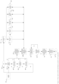
- the data logging system 102 collects and logs data from the control systems installed onboard. The logged data are then presented to the IT layer components through a data adapter service 105. The data are then populated and distributed from the 111 data distribution service.
- the 111 data distribution service bus publishes and subscribes information across the connected services.
- the dynamic positioning system 103 hosts the power plant setup advisor component 125, that helps to determine the optimal power plant setup.
- the power plant setup advisor is an OS- application (MFC) that loops through all the possible desired setups and provides one setup to be used in each iteration.
- MFC OS- application
- Each setup describes available gensets status, battery status, specific bus-tie breaker status and specific thruster connect status and can be an input to the worst-case failure (WSF) loop.
- WSF worst-case failure
- the optimizer is run on each setup in order to calculate the optimal genset/battery setup and the cost for this power plant setup.
- the power plant setups information is defined by configuration file or by a machine learning algorithm.
- the possible switchboard i.e., ring bus, open bus, closed bus, 2+1 split, 2-split or n split combinations and thruster configuration during a DP operation are defined in this configuration file.
- the legal DP class for each switchboard combination are included in the same configuration file.
- thruster Based on the power requirements of each connected switchboard the potential contribution of each genset is directly given.
- thruster it is complicated as it will contribute in at least two directions and typically in all three directions (surge, sway and yaw).
- thrusters are connected to different connected switchboards. Consequently, when disconnecting a thruster from a switchboard the power demands of other connected switchboard will increase. Each time a thruster is connected or disconnected the whole WSF loop must be re-run to find a new optimal genset setup.
- the thruster demand is given in three axes, being Surge, Sway and Yaw.
- the thruster demand is calculated by 103 DP.
- the output from 124 vessel response simulator is used if the analysis is run on changed settings in DP e.g., different heading or controller gain.
- the cost optimizer 125 gives long term advise for the power plant setup and is therefore necessary to smoothen the thrust demand so the thrust spikes do not influence on the result.
- a low pass filter is used to smoothen the thruster demand.
- the required power ramp for each connect switchboard depends on the computed thrust ramp.
- the thrust ramp is determined from the standard deviation of the thrust demand. The deviation is computed recursively for surge, sway, and yaw separately. The calculated thrust standard deviations are multiplied with two to obtain the thrust ramps.
- vessel response simulator 124 The purpose of vessel response simulator 124 is to generate the thrust demand and vessel response based on environmental disturbance (i.e., wind, current and waves). These environmental data are fetched from 118, 119 weather data service and adapter.
- the solution of 125 optimization problem is sent to 106 DP connector in IT layer from 103 DP via a web interface 104.
- the interface 104 fetches a token from the IT layer and is then verified for every post from 103 DP.
- the traffic between 103 and 106 are encrypted using a self-assigned certificate.
- the ship mode service 107 automatically detects the vessel main operation mode based on several signals likely, number of thrusters running, number of genset/battery running, shore power connection, vessel speed, water depth, vessel draft, vessel GPS position, vessel motions etc., 108 rest load analysis, determines the minimum rest load based on the vessel main operation mode information received from 107. The deviations from the baseline rest load are published back into 111 data distribution service.
- the power plant advise service 115 analyses the result from the 125 and determines the actions e.g., stopping/ starting of DG, thrusters, adjustments of kW/s etc., that needs to be forwarded to the control system via 113 control system connector.
- the efficiency and loss service 116 calculate the power loss and the operating efficiency of the equipment's including producers and consumers. The service also computes the power losses and efficiency based on the suggested configuration received from 125.
- the optimal power plant utilization service 109 subscribes to results from 108, 115, 116 and 107.
- the optimal power plant setup, minimum rest load, power loss and efficiency and vessel operation mode are used in 109 to determine the ideal load reference that gives minimum fuel consumption and maximum efficiency.
- the weather data adapter 119 and weather data service 118 are used to fetch the weather forecast for the ship geographical location using an internet-based cloud service. This weather forecast information are published and subscribed by other services namely, 108, 106. Using the DP connector 106 the weather parameters are forwarded to the vessel response simulator 124.
- the possible fuel consumption reduction based on the results from 109 is computed and forwarded to the balance profile 112.
- the fuel consumption reduction is used to calculate the achievable emission reduction in 117 and transferred to balance profile.
- the reduction in maintenance cost based on the reduction in running hours is computed in 114.
- the consolidated information from all the mentioned services in 126 are utilized in 112 to determine a combined index score based on the achievable energy efficiency and redundancy margin.
- the control system connector 113 is used to send the combined index and the optimal power plant setup recommendations to the 127-control system layer via 120.
- the connector operates in the same mechanism as 104.
- the system 127 includes options for selection of main system mode 121 and power system mode 122. It also accommodates the EMS 123 which manages the power generation systems safely, reliably, and economically.
- the different main system modes 121 of a vessel are shore connection, harbour, maneuvering, transit slow, transit fast, transit full speed, transit max speed, DP propeller, DP thruster, anchor and silent operation etc.,
- the ship mode service 107 in 126 determines automatically one of the main modes as mentioned earlier.
- the power plant For each of the main modes, it is possible for 123 to configure the power plant in any of the power system mode.
- the power system mode depends on the configuration of main engine, hybrid shaft generator, auxiliary engines, energy storage unit, grid converters, shore connections etc.,
- the combined index and optimal power plant configurations are processed in 123 to determine if a change in the power system mode is required to follow the suggestions. If the combined index from the balance profile falls within the acceptable limit, then the adaptation is performed automatically by EMS 123.
- balance profile 200 inclusive of calculator service for combined index is shown. From the data distribution service 201 the suggested actions and results from other services of 126 are presented to 202. Based on the recommended setups a value of energy efficiency index 203 and vessel redundancy margin index 204 are calculated. In section, balance profile there are examples on how the energy efficiency index and vessel redundancy index are calculated for each individual actions.
- table 1 illustrates the situation where an offshore vessel performs a DP operation in two split switchboard configurations with two gensets connected on each switchboard segments. All thrusters running in the two switchboard segments are running and enabled in DP system.
- Table 1 Present State Combined index value for DP operation
- Present State Energy Efficiency components Score Redundancy Margin Components Score Number of Engines 0.1 Ship Position deviation 0.45 Number of Thrusters 0.11 Ship Motion 0.09
- Fuel oil consumption/Emission 0.11 Ramp factor of producers and consumers 0.29 Rest Load 0.2 Heading deviation 0.47 Electrical Efficiency and Loss 0.14 Spinning Reserve 0.16 Power Available 0.12 Redundancy requirement 0.03 Operational Mode requirement 0.06
- DP Consequence 0.09 Weighted Score 0.23 Weighted Score 0.26 Combined index 0.1
- the scores for the energy efficiency and redundancy margin are in this case the mean value of the individual scores for each element, but may be weighted differently, either automatically through analysis of previous situations or by an operator.
- the combined index is determined by setting a base and target value for energy efficiency and redundancy margin scores. Then mapping the two scores to a common index range and assign them dynamic weights for them according to operation mode. Finally, sum up the weighted score values for each score.
- the weights may be predetermined or dynamically adjusted based on machine learning algorithms and continuously samples information related to the performance of the system.
- Table 1 results in a very low combined index, which is not optimal and should result in adjustments in the system, for example by increasing the number of producers, e.g. generators, in the system. This would increase the redundancy margin, but at the cost of the fuel consumption and emissions.
- the combined index would thus balance the different aspects of the system.
- the system may suggest a number of different adjustments of the system depending on the available equipment, and calculate the combined index for each of them, making the system or operator able to choose the best option based on the combined indexes.
- Table 2 Present State Combined index value for transit operation
- Present State Energy Efficiency components Score Redundancy Margin Components Score Number of Engines 0.1 Ship Position deviation 0.1 Number of Thrusters 0 Ship Motion 0.2
- Fuel oil consumption/Em ission 0.11 Ramp factor of producers and consumers 0.29 Rest Load 0.5 Heading deviation 0.1 Electrical Efficiency and Loss 0.14 Spinning Reserve 0.16 Power Available 0.12 Redundancy requirement 0.03 Main Engine Operation Mode 0.1 Operational Mode requirement 0.06
- the system would suggest different solutions based on the available resources in the system and calculate the combined index for the different configurations, making it possible to choose the solution giving the optimal value of the combined index, which in the example would be the highest value.
- the scores are computed using multiple parameters as mentioned in the Table 1 for DP and Table 2 for transit operation. Each parameter has its own weighted score depending on the vessel operation mode. The weighted score ranges from 0 to 1. For 204 the score 0 indicates very high redundancy margin and score 1 indicates very low redundancy margin. For 203 the score 0 indicates inefficient system and 1 indicates optimal system. These scores are then combined to produce a unified score in 205. In the combined index, a base value and target value are defined for energy efficiency and redundancy margin. The base and target value are adjusted dynamically according to the vessel operation mode. This combined index is then verified against a limit defined in 206 before a decision on forwarding to control system connector is made. The health status of services in 126 and the combined index value have to be within an acceptable limit to pass the validation.
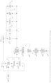
- FIG. 3 a flow diagram of an illustrative process of iEMS and balance profile for a DP operation is shown.
- the process starts at 303, where a decision mean change in weather is made.
- the limits to determine mean change in weather i.e., wind, current and wave are configurable, and the weather forecast is received 301 and posted 303.
- a change in power plant configuration e.g., bus breaker status, gensets status, thruster status, power system mode change etc.
- a change in DP configuration like change in heading, controller gains etc., are checked.
- a change in operation mode change is detected in 306.
- the power plant advisor 307 runs a power plant loop to determine an optimal setup with minimum number of gensets, battery and thrusters based on the selected DP class without exceeding the WSF condition.
- the results from 307 is post processed in optimal power plant utilization, where the power loss, efficiency, minimum rest load and power system mode are used to determine the ideal load reference for the producers that results in minimum fuel consumption and emission.
- the output for 308 is then used in 309 balance profile block where a combined index is computed.
- the combined index score is compared with acceptable limits and the results of 308 are then forwarded to control system via connecter 312 if it is approved by 311. If the score exceeds the limit, then the process returns to 309 to continue the same sequence for the next suggestion in the pipeline.
- the data distribution service 313 continuously publishes and collects data from the different services hosted in the IT layer. The results from these services are used in 308.
- FIG. 4 a flow diagram of an illustrative process of iEMS and balance profile for non-DP operation is shown.
- the process starts at 403, to detect a change in mean weather based on the weather forecast received 401.
- a change in power plant setup including the power system mode change 404 or operational mode change 405 are used to initiate the optimal power plant utilization service.
- the different power system modes for different vessel operation mode are defined in a configuration file.
- An optimizer using the mean load profile, peak load demands performs iteration on the defined modes to determine a best setup that provides minimum energy usage.
- the selected configuration shall also provide the required efficiency.
- the combined index from the balance profile block 407 is compared against the limits to determine if the recommendations can be forwarded to the control system via 409 and 410. Any deviation for the acceptable limit will result in aborting the sequence of transferring the advice to control system.
- the flow goes back to 407 to repeat the procedure based on the next advice in the queue.
- the other services hosted in IT layer perform the calculation based on the real time measurements received via the data distribution service 412.
- the present invention relates to a hierarchy is based on the industry approved ANSI/ISA -95 model.
- the physical components are placed in level 0 in the model, where process happens in milliseconds or microseconds.
- the measurements from level 0 are transmitted to controllers in level 1, where the actions happen in seconds.
- the level 2 hosts the monitoring and controlling elements are performed within in seconds.
- EMS is located in level 3 where PMS operation and selection of operation modes are performed.
- the iEMS including balance profile are placed in level between 3 and 4 i.e., 3.5.
- the novel control system connector links level 3.5 and 3.
- Level 5 is where the business planning and logistics are performed. This level has no relevance to the mechanism defined in this patent.
- the present invention relates to a system and related method for controlling a marine vessel comprising a number of devices.
- the devices including a number of power generators and consumers, further comprising sensors for monitoring the activity of the devices.
- the system also includes at least one processor calculating device score values representing the performance of the devices based on the sensor measurements and know characteristics of each device.
- the system includes a control unit connected to said devices and being configured to calculate an efficiency score value based on said device score values, the efficiency score value defining the efficiency of the system.
- the system is also configured to calculate the redundancy of the system based on the operation mode and/or load of the devices, and to calculate a redundancy margin index indicating the redundancy of the system devices according to predetermined scores for each operation mode related to the redundancy of the related device, and computing the efficiency and redundancy score values for the system.
- the system also further configured to calculate a combined index based on the efficiency score value and redundancy margin index.
- the system includes a set of setup configurations for the devices included in the system, and is configured to, at the instance of the combined index being outside a predetermined range, calculating the combined index for at least one alternate device setup and indicating the preferred setup based on a comparison between the combined index values. By choosing the highest combined index value the optimal mode of operation of the system may be used.
- the predetermined scores for each operation mode may be based on statistical analysis of previous stored data from corresponding situations or the predetermined scores and/or the predetermined range may be obtained from a machine learning unit analysing the system performance.
- the scores and range preferably being obtained from the machine learning unit are based on an analysis of previous data sampled in previous cases and/or feedback registered from system operators.
- the comparison of the combined indexes may also include a comparison of said computed or calculated scores, indexes and alternative device setups provided by a machine learning unit for optimization the system efficiency and redundancy based on an individual evaluation of the devices in addition to the efficiency and redundancy score values.
- the sensors in the system may also include one or more sensors for monitoring the vessel environment such as waves, current, wind and/or for monitoring of the vessel behavior, such as the position, motion, speed, heading of the vessel, the system thus being capable of weighting the scores depending on the situation, e.g. giving redundancy priority under difficult weather conditions.
- the system may also be configured to receive information regarding the vessel environment directly, such as a weather forecast, and being configured to take the environment information into account by a vessel response simulator, providing input to the system related to future conditions in the environment.
- the devices in the system may be defined as individual entities in the system, or may be grouped in clusters, such as a cluster for power generation, a cluster for thrusters, whereby the system calculates a common device score for each of the clusters.
- the system may also include a user interface including a display and interface such as a keyboard for allowing an operator to choose a setup based on said combined indexes, where the combined index is visualized for the operator to simplify the choice options, or for providing feedback from the user evaluating the performance.
- the choices and feedback may be registered by the system and used to optimize future automatic choices or the calculation of future scores and indexes, e.g. by a machine learning algorithm.
Landscapes
- Engineering & Computer Science (AREA)
- Power Engineering (AREA)
- Management, Administration, Business Operations System, And Electronic Commerce (AREA)
- Feedback Control In General (AREA)
Claims (9)
- Système de commande d'un navire marin comprenant un certain nombre de dispositifs, les dispositifs comportant un nombre de générateurs d'énergie et de consommateurs, comprenant en outre des capteurs pour surveiller l'activité des dispositifs, le système comportant au moins un processeur calculant les valeurs de score des dispositifs, le système comportant également une unité de commande connectée auxdits dispositifs et configurée pour calculer une valeur de score d'efficacité sur la base des valeurs de score des dispositifs, la valeur de score d'efficacité définissant l'efficacité du système,dans lequel le système est également configuré pour calculer la redondance du système sur la base du mode de fonctionnement et/ou de la charge des dispositifs, et pour calculer un indice de marge de redondance indiquant la redondance des dispositifs du système, selon les scores prédéterminés pour chaque mode de fonctionnement et en calculant les valeurs d'efficacité et de redondance,le système est également configuré pour calculer un indice combiné sur la base de la valeur de score d'efficacité et l'indice de marge de redondance, etle système comporte un ensemble de configurations d'installation pour les dispositifs inclus dans le système, le système étant configuré pour, lorsque l'indice combiné se situe en dehors d'une plage prédéterminée, calculer l'indice combiné pour au moins une installation alternative du dispositif et indiquer l'installation préférée sur la base d'une comparaison entre les valeurs de l'indice combiné.
- Système selon la revendication 1, dans lequel les scores prédéterminés pour chaque mode de fonctionnement sont basés sur une analyse statistique des données stockées précédemment dans des situations correspondantes.
- Système selon l'une quelconque des revendications précédentes, dans lequel les scores prédéterminés et/ou la plage prédéterminée sont obtenus à partir d'une unité d'apprentissage automatique.
- Système selon la revendication 3, dans lequel les scores et la plage obtenus par l'unité d'apprentissage automatique sont basés sur une analyse de données antérieures échantillonnées dans des cas précédents et/ou sur le retour d'informations enregistrées par les opérateurs du système.
- Système selon l'une quelconque des revendications précédentes, dans lequel la comparaison des indices combinés comporte également une comparaison des scores calculés, des indices et des configurations de dispositifs alternatifs fournis par une unité d'apprentissage automatique pour optimiser l'efficacité et la redondance du système.
- Système selon l'une quelconque des revendications précédentes, lesdits capteurs comprenant en outre un ou plusieurs capteurs pour la surveillance de l'environnement du navire, comme les vagues, le courant, le vent et/ou pour la surveillance du comportement du navire, comme la position, le mouvement, la vitesse, le cap du navire.
- Système selon l'une quelconque des revendications précédentes, dans lequel ledit système est également configuré pour recevoir des informations concernant l'environnement du navire, telles que des prévisions météorologiques, et est configuré pour prendre en compte les informations relatives à l'environnement par le biais d'un simulateur de réaction du navire, en fournissant au système des informations relatives aux conditions futures de l'environnement.
- Système selon l'une quelconque des revendications précédentes, dans lequel les dispositifs sont regroupés en grappes, par exemple une grappe pour la production d'énergie, une grappe pour les propulseurs, le système calculant un score commun pour chaque grappe.
- Système selon l'une quelconque des revendications précédentes, dans lequel le système comporte une interface utilisateur dotée d'un écran permettant à un opérateur de choisir une configuration sur la base de ces indices combinés.
Priority Applications (4)
| Application Number | Priority Date | Filing Date | Title |
|---|---|---|---|
| EP22156347.1A EP4228115B1 (fr) | 2022-02-11 | 2022-02-11 | Système de gestion d'énergie intelligent (iems) et profil d'équilibre |
| ES22156347T ES2994225T3 (en) | 2022-02-11 | 2022-02-11 | Intelligent energy management system (iems) and balance profile |
| FIEP22156347.1T FI4228115T3 (fi) | 2022-02-11 | 2022-02-11 | Älykäs energianhallintajärjestelmä (iems) ja tasapainoprofiili |
| DK22156347.1T DK4228115T3 (da) | 2022-02-11 | 2022-02-11 | Intelligent energistyresystem (EMS) og balanceprofil |
Applications Claiming Priority (1)
| Application Number | Priority Date | Filing Date | Title |
|---|---|---|---|
| EP22156347.1A EP4228115B1 (fr) | 2022-02-11 | 2022-02-11 | Système de gestion d'énergie intelligent (iems) et profil d'équilibre |
Publications (2)
| Publication Number | Publication Date |
|---|---|
| EP4228115A1 EP4228115A1 (fr) | 2023-08-16 |
| EP4228115B1 true EP4228115B1 (fr) | 2024-08-07 |
Family
ID=80447263
Family Applications (1)
| Application Number | Title | Priority Date | Filing Date |
|---|---|---|---|
| EP22156347.1A Active EP4228115B1 (fr) | 2022-02-11 | 2022-02-11 | Système de gestion d'énergie intelligent (iems) et profil d'équilibre |
Country Status (4)
| Country | Link |
|---|---|
| EP (1) | EP4228115B1 (fr) |
| DK (1) | DK4228115T3 (fr) |
| ES (1) | ES2994225T3 (fr) |
| FI (1) | FI4228115T3 (fr) |
Family Cites Families (10)
| Publication number | Priority date | Publication date | Assignee | Title |
|---|---|---|---|---|
| EP1447411A4 (fr) | 2001-11-02 | 2005-04-20 | Takeda Pharmaceutical | Nouvelle proteine, son adn et son utilisation |
| WO2012175624A1 (fr) * | 2011-06-22 | 2012-12-27 | Wärtsilä Finland Oy | Perfectionnement au rendement en carburant d'un moteur de propulsion de navire |
| NO334364B1 (no) | 2012-05-03 | 2014-02-17 | Kongsberg Maritime As | Prediktivt reguleringssystem. |
| NO335860B1 (no) | 2013-08-30 | 2015-03-09 | Kongsberg Maritime As | Kraftverksbeskyttelse |
| NO335595B1 (no) | 2013-08-30 | 2015-01-12 | Kongsberg Maritime As | Effektstyring i sjøfartøyer |
| EP2963769A1 (fr) * | 2014-07-04 | 2016-01-06 | Siemens Aktiengesellschaft | Système d'alimentation pour des navires en mer |
| WO2016062565A1 (fr) * | 2014-10-20 | 2016-04-28 | Siemens Aktiengesellschaft | Système d'alimentation de navire flottant |
| NO338463B1 (en) | 2015-03-20 | 2016-08-22 | Kongsberg Maritime As | Dynamic hybrid control |
| NO348156B1 (en) * | 2019-10-25 | 2024-09-09 | Kongsberg Maritime As | Power supply system |
| US11541763B2 (en) | 2020-02-11 | 2023-01-03 | Caterpillar Inc. | Hybrid energy storage system optimization strategy with intelligent adaptive control |
-
2022
- 2022-02-11 ES ES22156347T patent/ES2994225T3/es active Active
- 2022-02-11 DK DK22156347.1T patent/DK4228115T3/da active
- 2022-02-11 FI FIEP22156347.1T patent/FI4228115T3/fi active
- 2022-02-11 EP EP22156347.1A patent/EP4228115B1/fr active Active
Also Published As
| Publication number | Publication date |
|---|---|
| EP4228115A1 (fr) | 2023-08-16 |
| ES2994225T3 (en) | 2025-01-20 |
| FI4228115T3 (fi) | 2024-11-02 |
| DK4228115T3 (da) | 2024-10-28 |
Similar Documents
| Publication | Publication Date | Title |
|---|---|---|
| US20250062623A1 (en) | Intelligent energy management system (iems) and balance profile | |
| Li et al. | Robust coordination of a hybrid AC/DC multi-energy ship microgrid with flexible voyage and thermal loads | |
| CN102689685B (zh) | 基于在线可用功率的动力定位船推进器负载限制方法 | |
| CN113437741B (zh) | 船舶多能源供电系统的能量和健康管控系统、方法和船舶 | |
| CN109407635B (zh) | 一种船舶综合电力推进安全控制系统智能体系结构 | |
| Amy | Considerations in the design of naval electric power systems | |
| CN117985201A (zh) | 一种带燃料电池的双电机驱动的船舶控制方法与系统 | |
| CN116581816A (zh) | 应对非预期情况的船舶综合能源系统能量管理策略 | |
| Chen et al. | Robust real-time shipboard energy management system with improved adaptive model predictive control | |
| CN113806915A (zh) | 一种基于Anylogic平台的海上风电场运维仿真方法 | |
| Prousalidis et al. | Ship to shore electric interconnection: From adolescence to maturity | |
| Saushev et al. | Rapid identification of the technical condition of a marine electric power system | |
| EP4228115B1 (fr) | Système de gestion d'énergie intelligent (iems) et profil d'équilibre | |
| CN117471993A (zh) | 大型海洋风电柴油发电机组集群控制系统 | |
| CN121012126A (zh) | 集装箱船多工况下轴带发电与储能混合电力效率优化系统 | |
| CN119527526A (zh) | 基于模糊控制的混合动力船舶能量管理系统 | |
| Kougiatsos et al. | An intelligent agent-based resilient framework for marine vessel mission adaptations | |
| Mitropoulou et al. | Multi-objective optimisation and Energy Management: adapt your ship to every mission | |
| An et al. | A Two‐Stage Offline‐to‐Online Multiobjective Optimization Strategy for Ship Integrated Energy System Economical/Environmental Scheduling Problem | |
| CN115115108A (zh) | 一种船舶电网调度方法 | |
| Karim et al. | Rule-based power management for the all-electric ship | |
| Radan | Probability based generator commitment optimization in ship power system design | |
| Zhang et al. | Distributed Prescribed-Time Optimal Dispatch for Ship-Integrated Energy System with Environmental Awareness | |
| Reddy et al. | A Decentralized Droop-Based Power Management System for Ship Power Systems Using Hybrid Dynamical Systems Framework | |
| CN119882450B (zh) | 一种主辅动力混合船舶主辅动力转换控制方法及系统 |
Legal Events
| Date | Code | Title | Description |
|---|---|---|---|
| PUAI | Public reference made under article 153(3) epc to a published international application that has entered the european phase |
Free format text: ORIGINAL CODE: 0009012 |
|
| STAA | Information on the status of an ep patent application or granted ep patent |
Free format text: STATUS: THE APPLICATION HAS BEEN PUBLISHED |
|
| AK | Designated contracting states |
Kind code of ref document: A1 Designated state(s): AL AT BE BG CH CY CZ DE DK EE ES FI FR GB GR HR HU IE IS IT LI LT LU LV MC MK MT NL NO PL PT RO RS SE SI SK SM TR |
|
| STAA | Information on the status of an ep patent application or granted ep patent |
Free format text: STATUS: REQUEST FOR EXAMINATION WAS MADE |
|
| 17P | Request for examination filed |
Effective date: 20240213 |
|
| RBV | Designated contracting states (corrected) |
Designated state(s): AL AT BE BG CH CY CZ DE DK EE ES FI FR GB GR HR HU IE IS IT LI LT LU LV MC MK MT NL NO PL PT RO RS SE SI SK SM TR |
|
| GRAP | Despatch of communication of intention to grant a patent |
Free format text: ORIGINAL CODE: EPIDOSNIGR1 |
|
| STAA | Information on the status of an ep patent application or granted ep patent |
Free format text: STATUS: GRANT OF PATENT IS INTENDED |
|
| INTG | Intention to grant announced |
Effective date: 20240408 |
|
| RIC1 | Information provided on ipc code assigned before grant |
Ipc: H02J 3/14 20060101ALI20240322BHEP Ipc: H02J 3/38 20060101ALI20240322BHEP Ipc: H02J 3/00 20060101AFI20240322BHEP |
|
| GRAS | Grant fee paid |
Free format text: ORIGINAL CODE: EPIDOSNIGR3 |
|
| GRAA | (expected) grant |
Free format text: ORIGINAL CODE: 0009210 |
|
| STAA | Information on the status of an ep patent application or granted ep patent |
Free format text: STATUS: THE PATENT HAS BEEN GRANTED |
|
| RAP3 | Party data changed (applicant data changed or rights of an application transferred) |
Owner name: KONGSBERG MARITIME AS |
|
| AK | Designated contracting states |
Kind code of ref document: B1 Designated state(s): AL AT BE BG CH CY CZ DE DK EE ES FI FR GB GR HR HU IE IS IT LI LT LU LV MC MK MT NL NO PL PT RO RS SE SI SK SM TR |
|
| REG | Reference to a national code |
Ref country code: GB Ref legal event code: FG4D |
|
| REG | Reference to a national code |
Ref country code: CH Ref legal event code: EP |
|
| REG | Reference to a national code |
Ref country code: IE Ref legal event code: FG4D |
|
| REG | Reference to a national code |
Ref country code: DE Ref legal event code: R096 Ref document number: 602022005048 Country of ref document: DE |
|
| REG | Reference to a national code |
Ref country code: DK Ref legal event code: T3 Effective date: 20241022 |
|
| REG | Reference to a national code |
Ref country code: FI Ref legal event code: FGE |
|
| REG | Reference to a national code |
Ref country code: NL Ref legal event code: FP |
|
| REG | Reference to a national code |
Ref country code: SE Ref legal event code: TRGR |
|
| P01 | Opt-out of the competence of the unified patent court (upc) registered |
Free format text: CASE NUMBER: APP_56018/2024 Effective date: 20241014 |
|
| REG | Reference to a national code |
Ref country code: LT Ref legal event code: MG9D |
|
| PG25 | Lapsed in a contracting state [announced via postgrant information from national office to epo] |
Ref country code: NO Free format text: LAPSE BECAUSE OF FAILURE TO SUBMIT A TRANSLATION OF THE DESCRIPTION OR TO PAY THE FEE WITHIN THE PRESCRIBED TIME-LIMIT Effective date: 20241107 |
|
| REG | Reference to a national code |
Ref country code: AT Ref legal event code: MK05 Ref document number: 1712006 Country of ref document: AT Kind code of ref document: T Effective date: 20240807 |
|
| PG25 | Lapsed in a contracting state [announced via postgrant information from national office to epo] |
Ref country code: PT Free format text: LAPSE BECAUSE OF FAILURE TO SUBMIT A TRANSLATION OF THE DESCRIPTION OR TO PAY THE FEE WITHIN THE PRESCRIBED TIME-LIMIT Effective date: 20241209 Ref country code: GR Free format text: LAPSE BECAUSE OF FAILURE TO SUBMIT A TRANSLATION OF THE DESCRIPTION OR TO PAY THE FEE WITHIN THE PRESCRIBED TIME-LIMIT Effective date: 20241108 Ref country code: PL Free format text: LAPSE BECAUSE OF FAILURE TO SUBMIT A TRANSLATION OF THE DESCRIPTION OR TO PAY THE FEE WITHIN THE PRESCRIBED TIME-LIMIT Effective date: 20240807 |
|
| PG25 | Lapsed in a contracting state [announced via postgrant information from national office to epo] |
Ref country code: BG Free format text: LAPSE BECAUSE OF FAILURE TO SUBMIT A TRANSLATION OF THE DESCRIPTION OR TO PAY THE FEE WITHIN THE PRESCRIBED TIME-LIMIT Effective date: 20240807 |
|
| REG | Reference to a national code |
Ref country code: ES Ref legal event code: FG2A Ref document number: 2994225 Country of ref document: ES Kind code of ref document: T3 Effective date: 20250120 |
|
| PG25 | Lapsed in a contracting state [announced via postgrant information from national office to epo] |
Ref country code: LV Free format text: LAPSE BECAUSE OF FAILURE TO SUBMIT A TRANSLATION OF THE DESCRIPTION OR TO PAY THE FEE WITHIN THE PRESCRIBED TIME-LIMIT Effective date: 20240807 |
|
| PG25 | Lapsed in a contracting state [announced via postgrant information from national office to epo] |
Ref country code: IS Free format text: LAPSE BECAUSE OF FAILURE TO SUBMIT A TRANSLATION OF THE DESCRIPTION OR TO PAY THE FEE WITHIN THE PRESCRIBED TIME-LIMIT Effective date: 20241207 Ref country code: AT Free format text: LAPSE BECAUSE OF FAILURE TO SUBMIT A TRANSLATION OF THE DESCRIPTION OR TO PAY THE FEE WITHIN THE PRESCRIBED TIME-LIMIT Effective date: 20240807 |
|
| PG25 | Lapsed in a contracting state [announced via postgrant information from national office to epo] |
Ref country code: HR Free format text: LAPSE BECAUSE OF FAILURE TO SUBMIT A TRANSLATION OF THE DESCRIPTION OR TO PAY THE FEE WITHIN THE PRESCRIBED TIME-LIMIT Effective date: 20240807 |
|
| PG25 | Lapsed in a contracting state [announced via postgrant information from national office to epo] |
Ref country code: RS Free format text: LAPSE BECAUSE OF FAILURE TO SUBMIT A TRANSLATION OF THE DESCRIPTION OR TO PAY THE FEE WITHIN THE PRESCRIBED TIME-LIMIT Effective date: 20241107 |
|
| PG25 | Lapsed in a contracting state [announced via postgrant information from national office to epo] |
Ref country code: RS Free format text: LAPSE BECAUSE OF FAILURE TO SUBMIT A TRANSLATION OF THE DESCRIPTION OR TO PAY THE FEE WITHIN THE PRESCRIBED TIME-LIMIT Effective date: 20241107 Ref country code: PT Free format text: LAPSE BECAUSE OF FAILURE TO SUBMIT A TRANSLATION OF THE DESCRIPTION OR TO PAY THE FEE WITHIN THE PRESCRIBED TIME-LIMIT Effective date: 20241209 Ref country code: PL Free format text: LAPSE BECAUSE OF FAILURE TO SUBMIT A TRANSLATION OF THE DESCRIPTION OR TO PAY THE FEE WITHIN THE PRESCRIBED TIME-LIMIT Effective date: 20240807 Ref country code: NO Free format text: LAPSE BECAUSE OF FAILURE TO SUBMIT A TRANSLATION OF THE DESCRIPTION OR TO PAY THE FEE WITHIN THE PRESCRIBED TIME-LIMIT Effective date: 20241107 Ref country code: LV Free format text: LAPSE BECAUSE OF FAILURE TO SUBMIT A TRANSLATION OF THE DESCRIPTION OR TO PAY THE FEE WITHIN THE PRESCRIBED TIME-LIMIT Effective date: 20240807 Ref country code: IS Free format text: LAPSE BECAUSE OF FAILURE TO SUBMIT A TRANSLATION OF THE DESCRIPTION OR TO PAY THE FEE WITHIN THE PRESCRIBED TIME-LIMIT Effective date: 20241207 Ref country code: HR Free format text: LAPSE BECAUSE OF FAILURE TO SUBMIT A TRANSLATION OF THE DESCRIPTION OR TO PAY THE FEE WITHIN THE PRESCRIBED TIME-LIMIT Effective date: 20240807 Ref country code: GR Free format text: LAPSE BECAUSE OF FAILURE TO SUBMIT A TRANSLATION OF THE DESCRIPTION OR TO PAY THE FEE WITHIN THE PRESCRIBED TIME-LIMIT Effective date: 20241108 Ref country code: BG Free format text: LAPSE BECAUSE OF FAILURE TO SUBMIT A TRANSLATION OF THE DESCRIPTION OR TO PAY THE FEE WITHIN THE PRESCRIBED TIME-LIMIT Effective date: 20240807 Ref country code: AT Free format text: LAPSE BECAUSE OF FAILURE TO SUBMIT A TRANSLATION OF THE DESCRIPTION OR TO PAY THE FEE WITHIN THE PRESCRIBED TIME-LIMIT Effective date: 20240807 |
|
| PG25 | Lapsed in a contracting state [announced via postgrant information from national office to epo] |
Ref country code: SM Free format text: LAPSE BECAUSE OF FAILURE TO SUBMIT A TRANSLATION OF THE DESCRIPTION OR TO PAY THE FEE WITHIN THE PRESCRIBED TIME-LIMIT Effective date: 20240807 |
|
| PG25 | Lapsed in a contracting state [announced via postgrant information from national office to epo] |
Ref country code: EE Free format text: LAPSE BECAUSE OF FAILURE TO SUBMIT A TRANSLATION OF THE DESCRIPTION OR TO PAY THE FEE WITHIN THE PRESCRIBED TIME-LIMIT Effective date: 20240807 |
|
| PG25 | Lapsed in a contracting state [announced via postgrant information from national office to epo] |
Ref country code: CZ Free format text: LAPSE BECAUSE OF FAILURE TO SUBMIT A TRANSLATION OF THE DESCRIPTION OR TO PAY THE FEE WITHIN THE PRESCRIBED TIME-LIMIT Effective date: 20240807 |
|
| PG25 | Lapsed in a contracting state [announced via postgrant information from national office to epo] |
Ref country code: SK Free format text: LAPSE BECAUSE OF FAILURE TO SUBMIT A TRANSLATION OF THE DESCRIPTION OR TO PAY THE FEE WITHIN THE PRESCRIBED TIME-LIMIT Effective date: 20240807 |
|
| REG | Reference to a national code |
Ref country code: DE Ref legal event code: R097 Ref document number: 602022005048 Country of ref document: DE |
|
| PLBE | No opposition filed within time limit |
Free format text: ORIGINAL CODE: 0009261 |
|
| STAA | Information on the status of an ep patent application or granted ep patent |
Free format text: STATUS: NO OPPOSITION FILED WITHIN TIME LIMIT |
|
| 26N | No opposition filed |
Effective date: 20250508 |
|
| PG25 | Lapsed in a contracting state [announced via postgrant information from national office to epo] |
Ref country code: MC Free format text: LAPSE BECAUSE OF FAILURE TO SUBMIT A TRANSLATION OF THE DESCRIPTION OR TO PAY THE FEE WITHIN THE PRESCRIBED TIME-LIMIT Effective date: 20240807 |
|
| PG25 | Lapsed in a contracting state [announced via postgrant information from national office to epo] |
Ref country code: LU Free format text: LAPSE BECAUSE OF NON-PAYMENT OF DUE FEES Effective date: 20250211 |
|
| REG | Reference to a national code |
Ref country code: BE Ref legal event code: MM Effective date: 20250228 |
|
| PG25 | Lapsed in a contracting state [announced via postgrant information from national office to epo] |
Ref country code: FR Free format text: LAPSE BECAUSE OF NON-PAYMENT OF DUE FEES Effective date: 20250228 |
|
| PG25 | Lapsed in a contracting state [announced via postgrant information from national office to epo] |
Ref country code: BE Free format text: LAPSE BECAUSE OF NON-PAYMENT OF DUE FEES Effective date: 20250228 |
|
| PG25 | Lapsed in a contracting state [announced via postgrant information from national office to epo] |
Ref country code: IE Free format text: LAPSE BECAUSE OF NON-PAYMENT OF DUE FEES Effective date: 20250211 |
|
| REG | Reference to a national code |
Ref country code: CH Ref legal event code: U11 Free format text: ST27 STATUS EVENT CODE: U-0-0-U10-U11 (AS PROVIDED BY THE NATIONAL OFFICE) Effective date: 20260301 |
|
| PGFP | Annual fee paid to national office [announced via postgrant information from national office to epo] |
Ref country code: NL Payment date: 20260226 Year of fee payment: 5 |
|
| PGFP | Annual fee paid to national office [announced via postgrant information from national office to epo] |
Ref country code: SE Payment date: 20260227 Year of fee payment: 5 |
|
| PGFP | Annual fee paid to national office [announced via postgrant information from national office to epo] |
Ref country code: ES Payment date: 20260302 Year of fee payment: 5 |
|
| PGFP | Annual fee paid to national office [announced via postgrant information from national office to epo] |
Ref country code: DK Payment date: 20260225 Year of fee payment: 5 Ref country code: DE Payment date: 20260227 Year of fee payment: 5 |
|
| PG25 | Lapsed in a contracting state [announced via postgrant information from national office to epo] |
Ref country code: RO Free format text: LAPSE BECAUSE OF FAILURE TO SUBMIT A TRANSLATION OF THE DESCRIPTION OR TO PAY THE FEE WITHIN THE PRESCRIBED TIME-LIMIT Effective date: 20240807 |
|
| PGFP | Annual fee paid to national office [announced via postgrant information from national office to epo] |
Ref country code: FI Payment date: 20260225 Year of fee payment: 5 Ref country code: IT Payment date: 20260219 Year of fee payment: 5 |
|
| PGFP | Annual fee paid to national office [announced via postgrant information from national office to epo] |
Ref country code: CH Payment date: 20260301 Year of fee payment: 5 |