EP4228358A1 - Procédés et appareils d'émission et de réception de signaux - Google Patents
Procédés et appareils d'émission et de réception de signaux Download PDFInfo
- Publication number
- EP4228358A1 EP4228358A1 EP20961081.5A EP20961081A EP4228358A1 EP 4228358 A1 EP4228358 A1 EP 4228358A1 EP 20961081 A EP20961081 A EP 20961081A EP 4228358 A1 EP4228358 A1 EP 4228358A1
- Authority
- EP
- European Patent Office
- Prior art keywords
- frequency domain
- frequency
- time
- signal
- resource
- Prior art date
- Legal status (The legal status is an assumption and is not a legal conclusion. Google has not performed a legal analysis and makes no representation as to the accuracy of the status listed.)
- Pending
Links
Images




Classifications
-
- H—ELECTRICITY
- H04—ELECTRIC COMMUNICATION TECHNIQUE
- H04W—WIRELESS COMMUNICATION NETWORKS
- H04W72/00—Local resource management
- H04W72/04—Wireless resource allocation
- H04W72/044—Wireless resource allocation based on the type of the allocated resource
-
- H—ELECTRICITY
- H04—ELECTRIC COMMUNICATION TECHNIQUE
- H04L—TRANSMISSION OF DIGITAL INFORMATION, e.g. TELEGRAPHIC COMMUNICATION
- H04L5/00—Arrangements affording multiple use of the transmission path
- H04L5/003—Arrangements for allocating sub-channels of the transmission path
- H04L5/0048—Allocation of pilot signals, i.e. of signals known to the receiver
- H04L5/0051—Allocation of pilot signals, i.e. of signals known to the receiver of dedicated pilots, i.e. pilots destined for a single user or terminal
-
- H—ELECTRICITY
- H04—ELECTRIC COMMUNICATION TECHNIQUE
- H04W—WIRELESS COMMUNICATION NETWORKS
- H04W72/00—Local resource management
- H04W72/02—Selection of wireless resources by user or terminal
-
- H—ELECTRICITY
- H04—ELECTRIC COMMUNICATION TECHNIQUE
- H04W—WIRELESS COMMUNICATION NETWORKS
- H04W8/00—Network data management
- H04W8/22—Processing or transfer of terminal data, e.g. status or physical capabilities
- H04W8/24—Transfer of terminal data
-
- H—ELECTRICITY
- H04—ELECTRIC COMMUNICATION TECHNIQUE
- H04L—TRANSMISSION OF DIGITAL INFORMATION, e.g. TELEGRAPHIC COMMUNICATION
- H04L5/00—Arrangements affording multiple use of the transmission path
- H04L5/0001—Arrangements for dividing the transmission path
- H04L5/0003—Two-dimensional division
- H04L5/0005—Time-frequency
- H04L5/0007—Time-frequency the frequencies being orthogonal, e.g. OFDM(A) or DMT
-
- H—ELECTRICITY
- H04—ELECTRIC COMMUNICATION TECHNIQUE
- H04W—WIRELESS COMMUNICATION NETWORKS
- H04W64/00—Locating users or terminals or network equipment for network management purposes, e.g. mobility management
Definitions
- This application relates to the field of wireless communication technologies, and in particular, to a signal sending method, a signal receiving method, and an apparatus.
- a base station may perform positioning, channel estimation, or the like by measuring an uplink sounding reference signal (sounding reference signal, SRS) sent by a terminal device.
- SRS sounding reference signal
- An SRS used for positioning is also referred to as a positioning SRS (positioning SRS, pos-SRS).
- positioning SRS positioning SRS, pos-SRS
- one solution is to separately transmit a plurality of positioning signals in a plurality of narrowbands (for example, subcarriers) at different frequencies in a frequency hopping manner.
- the base station may process the plurality of positioning signals transmitted in the plurality of narrowbands at the different frequencies as a whole, so that the plurality of positioning signals are considered as a signal transmitted in a "large broadband" including a plurality of narrowbands.
- one "large broadband” signal can be obtained based on a plurality of "small broadband” signals, to improve positioning precision.
- a radio frequency transmit channel of the terminal device needs to be retuned to adapt to a frequency used during frequency hopping transmission. Due to retuning of the radio frequency transmit channel, there is a difference between positioning signals transmitted in different narrowbands. This difference affects positioning precision.
- An objective of implementations of this application is to provide a signal sending method, a signal receiving method, and an apparatus, to resolve a problem of how to reduce a difference between signals transmitted through frequency hopping.
- an embodiment of this application provides a signal sending method.
- the method is performed by a terminal device or a module in a terminal device.
- the terminal device executes the method is used for description.
- the method includes: generating M signals; and sending the M signals on M time-frequency resource elements, where a first signal includes the M signals, the M signals are in a one-to-one correspondence with the M time-frequency resource elements, at least two of the M time-frequency resource elements partially overlap in frequency domain, any two of the M time-frequency resource elements do not overlap in time domain, and M is an integer greater than 1.
- the at least two time-frequency resource elements include a first time-frequency resource element and a second time-frequency resource element; and a frequency domain resource of the first time-frequency resource element includes a first frequency domain resource and a second frequency domain resource, the first frequency domain resource is an overlapping part of the first time-frequency resource element and the second time-frequency resource element in frequency domain, and the second frequency domain resource is a part other than the first frequency domain resource in the frequency domain resource of the first time-frequency resource element.
- the at least two time-frequency resource elements further include a third time-frequency resource element; and the second frequency domain resource includes a third frequency domain resource and a fourth frequency domain resource, the third frequency domain resource is an overlapping part of the first time-frequency resource element and the third time-frequency resource element in frequency domain, and the fourth frequency domain resource is a part other than the third frequency domain resource in the second frequency domain resource.
- the M signals include a first signal and a second signal, the first signal corresponds to the first time-frequency resource element, and the second signal corresponds to the second time-frequency resource element; and a bit sequence corresponding to a part that is of the first signal and that is mapped to the first frequency domain resource and a bit sequence corresponding to a part that is of the second signal and that is mapped to the first frequency domain resource has a same value and opposite symbols.
- the M signals further include the first signal and the second signal, and the third signal corresponds to the third time-frequency resource element; and a bit sequence corresponding to a part that is of the first signal and that is mapped to the third frequency domain resource and a bit sequence corresponding to a part that is of the third signal and that is mapped to the third frequency domain resource have a same value and opposite symbols.
- the M signals are positioning reference signals; and a part that is of the M signals and that is mapped to an overlapping frequency domain resource is a phase tracking reference signal, and a part that is of the M signals and that is mapped to a frequency domain resource other than the overlapping frequency domain resource is a positioning reference signal.
- the method further includes: sending capability information to a network device, where the capability information indicates a frequency division capability of a phase-locked loop.
- this application provides a signal receiving method.
- the method is performed by a network device or a module in a network device.
- a network device executes the method.
- the method includes:
- the M signals include at least two signals, and the at least two signals correspond to the at least two time-frequency resource elements.
- the method further includes:
- the at least two time-frequency resource elements include a first time-frequency resource element and a second time-frequency resource element; and a frequency domain resource of the first time-frequency resource element includes a first frequency domain resource and a second frequency domain resource, the first frequency domain resource is an overlapping part of the first time-frequency resource element and the second time-frequency resource element in frequency domain, and the second frequency domain resource is a part other than the first frequency domain resource in the frequency domain resource of the first time-frequency resource element.
- the at least two time-frequency resource elements further include a third time-frequency resource element; and the second frequency domain resource includes a third frequency domain resource and a fourth frequency domain resource, the third frequency domain resource is an overlapping part of the first time-frequency resource element and the third time-frequency resource element in frequency domain, and the fourth frequency domain resource is a part other than the third frequency domain resource in the second frequency domain resource.
- the M signals include a first signal and a second signal, the first signal corresponds to the first time-frequency resource element, and the second signal corresponds to the second time-frequency resource element; and a bit sequence corresponding to a part that is of the first signal and that is mapped to the first frequency domain resource and a bit sequence corresponding to a part that is of the second signal and that is mapped to the first frequency domain resource has a same value and opposite symbols.
- the M signals further include the first signal and the second signal, and the third signal corresponds to the third time-frequency resource element; and a bit sequence corresponding to a part that is of the first signal and that is mapped to the third frequency domain resource and a bit sequence corresponding to a part that is of the third signal and that is mapped to the third frequency domain resource have a same value and opposite symbols.
- the M signals are positioning reference signals; or a part that is of the M signals and that is mapped to an overlapping frequency domain resource is a phase tracking reference signal, and a part that is of the M signals and that is mapped to a frequency domain resource other than the overlapping frequency domain resource is a positioning reference signal.
- this application further provides a communication apparatus.
- the communication apparatus has a function of implementing any method provided in the first aspect.
- the communication apparatus may be implemented by hardware, or may be implemented by hardware executing corresponding software.
- the hardware or the software includes one or more units or modules corresponding to the foregoing function.
- the communication apparatus includes a processor.
- the processor is configured to support the communication apparatus in performing a corresponding function of the terminal device in the foregoing method.
- the communication apparatus may further include a memory.
- the memory may be coupled to the processor, and the memory stores program instructions and data that are necessary for the communication apparatus.
- the communication apparatus further includes a communication interface, and the communication interface is configured to support communication between the communication apparatus and a device such as a network device.
- the communication apparatus includes corresponding functional modules, configured to implement the steps in the foregoing method.
- the function may be implemented by hardware, or may be implemented by hardware executing corresponding software.
- the hardware or the software includes one or more modules corresponding to the foregoing function.
- a structure of the communication apparatus includes a processing unit and a communication unit. These units may perform corresponding functions in the foregoing method examples. For details, refer to the descriptions in the method provided in the first aspect. The details are not described herein again.
- this application further provides a communication apparatus.
- the communication apparatus has a function of implementing any method provided in the second aspect.
- the communication apparatus may be implemented by hardware, or may be implemented by hardware executing corresponding software.
- the hardware or the software includes one or more units or modules corresponding to the foregoing function.
- the communication apparatus includes a processor.
- the processor is configured to support the communication apparatus in performing a corresponding function of the network device in the foregoing method.
- the communication apparatus may further include a memory.
- the memory may be coupled to the processor, and the memory stores program instructions and data that are necessary for the communication apparatus.
- the communication apparatus further includes a communication interface.
- the communication interface is configured to support communication between the communication apparatus and a device such as a terminal device.
- the communication apparatus includes corresponding functional modules, configured to implement the steps in the foregoing method.
- the function may be implemented by hardware, or may be implemented by executing corresponding software by hardware.
- the hardware or the software includes one or more modules corresponding to the foregoing function.
- a structure of the communication apparatus includes a processing unit and a communication unit. These units may perform corresponding functions in the foregoing method examples. For details, refer to the descriptions in the method provided in the first aspect. The details are not described herein again.
- a communication apparatus includes a processor and a communication interface.
- the communication interface is configured to: receive a signal from a communication apparatus other than the communication apparatus and transmit the signal to the processor, or send a signal from the processor to a communication apparatus other than the communication apparatus.
- the processor is configured to implement, by using a logic circuit or executing code instructions, the method provided in the first aspect.
- a communication apparatus includes a processor and a communication interface.
- the communication interface is configured to: receive a signal from a communication apparatus other than the communication apparatus and transmit the signal to the processor, or send a signal from the processor to a communication apparatus other than the communication apparatus.
- the processor is configured to implement, by using a logic circuit or executing code instructions, the method provided in the second aspect.
- a computer-readable storage medium stores a computer program or instructions, and when the computer program or the instructions are executed by a processor, the method provided in the first aspect or the second aspect is implemented.
- a computer program product including instructions is provided. When the instructions are run by a processor, the method provided in the first aspect or the second aspect is implemented.
- a chip system includes a processor, and may further include a memory, to implement the method provided in the first aspect or the second aspect.
- the chip system may include a chip, or may include a chip and another discrete component.
- a communication system includes the apparatus (for example, the terminal device) according to the third aspect and the apparatus (for example, the network device) according to the fourth aspect.
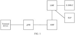
- FIG. 1 is a schematic diagram of a 5G core network-based positioning architecture to which an embodiment of this application is applicable.
- functions of functional entities may be as follows:
- the terminal device may send a reference signal, for example, a pos-SRS, so that a device such as a next generation NodeB (next generation NodeB, gNB) on a network side positions the terminal device based on the pos-SRS.
- a reference signal for example, a pos-SRS
- a device such as a next generation NodeB (next generation NodeB, gNB) on a network side positions the terminal device based on the pos-SRS.
- gNB next generation NodeB
- the gNB may measure a reference signal from a terminal device, to obtain measurement information, and transfer the measurement information to a location management function (location management function, LMF) network element.
- the gNB may further provide another function, for example, provide a wireless connection for the terminal device.
- the LMF network element may be responsible for supporting different types of location services related to a target terminal device, including positioning the terminal device and transferring assistance data to the terminal device.
- a control plane and a user plane of the LMF network element are respectively an enhanced serving mobile location center (enhanced serving mobile location center, E-SMLC) network element and a secure user plane location platform (secure user plane location platform, SLP) network element.
- E-SMLC enhanced serving mobile location center
- SLP secure user plane location platform
- the AMF network element may receive a location service request related to a terminal device, or the AMF network element may perform a location service, and forward the location service request to an LMF. After obtaining location information returned by the terminal device, the AMF network element returns the related location information to a location service (location service, LCS) entity.
- location service location service
- the terminal device may be a device that has a wireless transceiver function or a chip that can be disposed in any device, or may be referred to as user equipment (user equipment, UE), an access terminal, a subscriber unit, a subscriber station, a mobile station, a mobile console, a mobile device, a user terminal, a wireless communication device, or a user apparatus.
- user equipment user equipment
- UE user equipment
- an access terminal a subscriber unit, a subscriber station, a mobile station, a mobile console, a mobile device, a user terminal, a wireless communication device, or a user apparatus.
- the terminal device in embodiments of this application may be a mobile phone (mobile phone), a tablet computer (Pad), a computer having a wireless transceiver function, a virtual reality (virtual reality, VR) terminal, an augmented reality (augmented reality, AR) terminal, a wireless terminal in industrial control (industrial control), a wireless terminal in self driving (self driving), a wireless terminal in remote medical (remote medical), a wireless terminal in a smart grid (smart grid), or the like.
- the terminal device may be a reduced-capability (Reduced Capability, REDCAP) terminal device, or may be a legacy-capability, normal-capability, or high-capability terminal device, or may be referred to as a legacy (legacy) terminal device or a normal (normal) terminal device.
- the REDCAP terminal device and the legacy terminal device are different in terms of at least a bandwidth capability. For example, a maximum bandwidth supported by the REDCAP terminal device is low, for example, 50 MHz, 40 MHz, 20 MHz, 15 MHz, 10 MHz, or 5 MHz, and a maximum bandwidth supported by the legacy terminal device is high, for example, 100 MHz.
- the network device may be a gNB in an NR system, an evolved NodeB (evolved NodeB, eNB) in an LTE system, or the like.
- the network device may include a central unit (central unit, CU) and a distributed unit (distributed unit, DU).
- interaction between the terminal device and the network device is used as an example for description.
- the method provided in embodiments of this application may be further applied to interaction between other entities, for example, interaction between a chip or a module in the terminal device and a chip or a module in the network device.
- a chip or a module executes the method, reference may be made to the descriptions in embodiments of this application. Details are not described herein.
- FIG. 2 is a schematic flowchart of a signal transmission method according to an embodiment of this application. Refer to FIG. 2 . The method includes the following steps.
- Step 201 A terminal device generates M signals.
- M is an integer greater than 1.
- the terminal device specifically generates the M signals is not limited in this embodiment of this application. Details are not described herein.
- Step 202 The terminal device sends the M signals on M time-frequency resource elements.
- At least two of the M time-frequency resource elements partially overlap in frequency domain, and any two of the M time-frequency resource elements do not overlap in time domain.
- every two of the time-frequency elements may overlap each other In other words, there may be no frequency domain resource that belongs to three time-frequency resource elements.
- a time-frequency resource element #1 and a time-frequency resource element #2 overlap in frequency domain
- the time-frequency resource element #1 and a time-frequency resource element #3 overlap in frequency domain
- the time-frequency resource element #2 and the time-frequency resource element #3 do not overlap in frequency domain.
- partial overlapping in frequency domain may be understood as follows: For every two time-frequency resource elements that partially overlap in frequency domain, an overlapping frequency domain resource is only a part of a frequency domain resource of each of the two time-frequency resource elements.
- the time-frequency resource element #1 and the time-frequency resource element #2 partially overlap
- an overlapping frequency domain resource is only a part of the time-frequency resource element #1 and is only a part of the time-frequency resource element #2.
- Step 203 A network device determines the M time-frequency resource elements.
- Step 204 The network device receives the M signals on the M time-frequency resource elements.
- the network device estimates a phase difference between the at least two signals based on a partially overlapping signal of the at least two signals in frequency domain, and performs phase compensation on the at least two phases based on the phase difference.
- the M signals are in a one-to-one correspondence with the M time-frequency resource elements.
- one of the M time-frequency resource elements is used to carry one of the M signals.
- One of the M signals may correspond to one sending occasion, and M sending occasions corresponding to the M signals may be M consecutive sending occasions.
- the M time-frequency resource elements may have at least one of the following features: 1.
- the M time-frequency resource elements are M consecutive time-frequency resource elements.
- time-frequency resource elements there is a time interval between adjacent time-frequency resource elements in time domain.
- signals S 1 and S 2 are respectively carried on time-frequency resource elements X1 and X2.
- a time interval is included between the two adjacent time-frequency resource elements X1 and X2.
- the time interval includes at least one or more orthogonal frequency division multiplexing (orthogonal frequency division multiplexing, OFDM) symbols or slots, and the time interval may be greater than or equal to a time required by a radio frequency transmit channel of a terminal device to perform radio frequency retuning.
- OFDM orthogonal frequency division multiplexing
- the M time-frequency resource elements may correspond to M bandwidth units in frequency domain, and one time-frequency resource element corresponds to one bandwidth unit.
- the bandwidth unit may include at least one subcarrier or include at least one bandwidth part (bandwidth part, BWP).
- BWP bandwidth part
- the bandwidth unit may be a preset fixed bandwidth.
- the bandwidth unit is a 20 MHz bandwidth.
- one of the M time-frequency resource elements may include at least one OFDM symbol in time domain.
- a bandwidth of the signal may be equal to a bandwidth of a time-frequency resource element carrying the signal, that is, the signal occupies a frequency domain range of the entire time-frequency resource element in frequency domain.
- duration of a time-frequency resource element in time domain is T OFDM symbols
- T is a number greater than 0
- a bandwidth in frequency domain is 20 MHz.
- a signal carried in the time-frequency resource element may occupy some OFDM symbols in time domain, and occupy 20 MHz in frequency domain, that is, occupy the entire bandwidth of the time-frequency resource element.
- Implementation 1 Frequency domain resources occupied by at least two of the M signals in frequency domain partially overlap, and time domain resources occupied by any two of the M signals in time domain do not overlap.
- the signal carried in the time-frequency resource element occupies the entire bandwidth of the time-frequency resource element, this implementation may also be understood as follows: At least two of the M time-frequency resource elements partially overlap in frequency domain, and any two of the M time-frequency resource elements do not overlap in time domain.
- the time-frequency resource element may partially overlap a plurality of time-frequency resource elements in frequency domain.
- the signal may partially overlap a plurality of signals in frequency domain.
- the two signals are adj acent in time domain.
- sending occasions corresponding to signals carried in the two time-frequency resource elements are adjacent in time domain.
- each of the M time-frequency resource elements partially overlaps one or two time-frequency resource elements in frequency domain is used for description.
- signals S 1 to S 5 are respectively carried on time-frequency resource elements X1 to X5, and adjacent time-frequency resource elements partially overlap in frequency domain.
- Maximum frequency values (or minimum frequency values) corresponding to the time-frequency resource element X1 to the time-frequency resource element X5 increase sequentially, or center frequencies of the M time-frequency resource elements increase sequentially.
- each of the M time-frequency resource elements partially overlaps one or two time-frequency resource elements in time domain is used for description.
- signals S 1 to S 5 are respectively carried on time-frequency resource elements X1 to X5, and adjacent time-frequency resource elements partially overlap in frequency domain.
- Maximum frequency values (or minimum frequency values) corresponding to the time-frequency resource element X1 to the time-frequency resource element X5 decrease sequentially, or center frequencies of the M time-frequency resource elements decrease sequentially.
- sending occasions corresponding to the two signals may be adjacent or may not be adjacent in time domain.
- sending occasions corresponding to signals carried in the two time-frequency resource elements may be adjacent or may not be adjacent in time domain.
- signals S 1 to S 5 are respectively sent on five consecutive sending occasions in time domain, and five time-frequency resource elements corresponding to the five sending occasions are a time-frequency resource element X1 to a time-frequency resource element X5.
- the time-frequency resource element X1 partially overlaps the time-frequency resource element X3 in frequency domain; the time-frequency resource element X2 partially overlaps the time-frequency resource element X4 and the time-frequency resource element X5 in frequency domain; the time-frequency resource element X3 partially overlaps the time-frequency resource element X1 and the time-frequency resource element X5 in frequency domain; the time-frequency resource element X4 partially overlaps the time-frequency resource element X2 in frequency domain; and the time-frequency resource element X5 partially overlaps the time-frequency resource element X2 and the time-frequency resource element X3 in frequency domain.
- the signal S 1 partially overlaps the signal S 3 in frequency domain; the signal S 2 partially overlaps the signal S 4 and the signal S 5 in frequency domain; the signal S 3 partially overlaps the signal S 1 and the signal S 5 in frequency domain; the signal S 4 partially overlaps the signal S 2 in frequency domain; and the signal S 5 partially overlaps the signal S 2 and the signal S 3 in frequency domain.
- signals S 1 to S 5 are respectively sent on five consecutive sending occasions in time domain, and five time-frequency resource elements corresponding to the five sending occasions are a time-frequency resource element X1 to a time-frequency resource element X5.
- the time-frequency resource element X1 partially overlaps the time-frequency resource element X3 and the time-frequency resource element X4 in frequency domain; the time-frequency resource element X2 partially overlaps the time-frequency resource element X3 in frequency domain; the time-frequency resource element X3 partially overlaps the time-frequency resource element X1 and the time-frequency resource element X2 in frequency domain; the time-frequency resource element X4 partially overlaps the time-frequency resource element X1 and the time-frequency resource element X5 in frequency domain; and the time-frequency resource element X5 partially overlaps the time-frequency resource element X4 in frequency domain.
- the signal S 1 partially overlaps the signal S 3 and the signal S 4 in frequency domain
- the signal S 2 partially overlaps the signal S 3 in frequency domain
- the signal S 3 partially overlaps the signal S 1 and the signal S 2 in frequency domain
- the signal S 4 partially overlaps the signal S 1 and the signal S 5 in frequency domain
- the signal S 5 partially overlaps the signal S 4 in frequency domain.
- signals S 1 to S 5 are respectively sent on five consecutive sending occasions in time domain, and five time-frequency resource elements corresponding to the five sending occasions are a time-frequency resource element X1 to a time-frequency resource element X5. Any two of the time-frequency resource elements X1 to X5 do not overlap in frequency domain, that is, frequency domain resources occupied by any two of the signals S 1 to S 5 do not overlap.
- a center frequency of the time-frequency resource element X1 to a center frequency of the time-frequency resource element X5 increase sequentially (or in ascending order in frequency domain) is used for description.
- the M time-frequency resource elements may be distributed in frequency domain in another form.
- FIG. 9 is a schematic diagram of a location of another time-frequency resource element according to this application.
- a time-frequency resource element X1 to a time-frequency resource element X5 are not distributed in descending order or ascending order in frequency domain, but are distributed out of order without a specific rule.
- a frequency domain resource occupied by the first signal may include two parts: a first frequency domain resource and a second frequency domain resource.
- the second frequency domain resource may further include two parts: a third frequency domain resource and a fourth frequency domain resource.
- the third frequency domain resource may be located between the first frequency domain resource and the fourth frequency domain resource.
- a sum of a bandwidth corresponding to the first frequency domain resource and a bandwidth corresponding to the second frequency domain resource is less than or equal to a bandwidth of the first signal. Specific values of the bandwidth corresponding to the first frequency domain resource and the bandwidth corresponding to the second frequency domain resource are not limited in this embodiment of this application.
- a sum of a bandwidth corresponding to the third frequency domain resource and a bandwidth corresponding to the fourth frequency domain resource is less than or equal to the bandwidth corresponding to the second frequency domain resource. Specific values of the bandwidth corresponding to the third frequency domain resource and the bandwidth corresponding to the fourth frequency domain resource are not limited in this embodiment of this application.
- the first frequency domain resource is an overlapping part of the frequency domain resource occupied by the first signal and a frequency domain resource occupied by the second signal
- the second frequency domain resource is a part other than the first frequency domain resource in the frequency domain resource occupied by the first signal.
- the fourth frequency domain resource is an overlapping part of the frequency domain resource occupied by the first signal and a frequency domain resource occupied by the third signal in frequency domain, and the third frequency domain resource is a part other than the fourth frequency domain resource in the second frequency domain resource.
- a frequency domain resource occupied by the signal S2 may include a first frequency domain resource F1 and a second frequency domain resource F2.
- the second frequency domain resource F2 may further include a third frequency domain resource F3 and a fourth frequency domain resource F4.
- the first frequency domain resource F1 occupied by the signal S2 may be a part that is in the frequency domain resource occupied by the signal S2 and that overlaps a frequency domain resource occupied by the signal S3;
- the fourth frequency domain resource F4 occupied by the signal S2 may be a part that is in the frequency domain resource occupied by the signal S2 and that overlaps a frequency domain resource occupied by the signal S1;
- the third frequency domain resource F3 occupied by the signal S2 may be a part other than the first frequency domain resource F1 and the third frequency domain resource F3 in the frequency domain resource occupied by the signal S2.
- a frequency domain resource occupied by the signal S1 may include a first frequency domain resource F1 and a second frequency domain resource F2.
- a frequency domain resource occupied by the signal S3 may include a first frequency domain resource F1 and a second frequency domain resource F2.
- the first frequency domain resource F1 occupied by the signal S1 may be a part that is in the frequency domain resource occupied by the signal S1 and that overlaps a frequency domain resource occupied by the signal S2; and a second frequency domain resource F2 occupied by the signal S2 may be a part other than a first frequency domain resource F1 in the frequency domain resource occupied by the signal S2.
- the first frequency domain resource F1 occupied by the signal S3 may be a part that is in the frequency domain resource occupied by the signal S3 and that overlaps the frequency domain resource occupied by the signal S2; and the second frequency domain resource F2 occupied by the signal S3 may be a part other than the first frequency domain resource F1 in the frequency domain resource occupied by the signal S3.
- a frequency domain resource occupied by the time-frequency resource element may include two parts: a first frequency domain resource and a second frequency domain resource.
- the second frequency domain resource may further include two parts: a third frequency domain resource and a fourth frequency domain resource.
- a bit sequence corresponding to a part that is of the first signal and that is mapped to the first frequency domain resource and a bit sequence corresponding to a part that is of the second signal and that is mapped to the first frequency domain resource have a same value.
- a bit sequence corresponding to a part that is of the first signal and that is mapped to the first frequency domain resource and a bit sequence corresponding to a part that is of the second signal and that is mapped to the first frequency domain resource have a same value and opposite symbols, where the " sign" herein is a positive sign or a negative sign.
- a phase difference between a phase of the signal that is of the first signal, that is mapped to the first frequency domain resource, and that corresponds to the bit sequence and a phase of the signal that is of the second signal, that is mapped to the first frequency domain resource, and that corresponds to the bit sequence may be 180°+N ⁇ 360°, where N is an integer.
- a bit sequence corresponding to a part that is of the first signal and that is mapped to the fourth frequency domain resource and a bit sequence corresponding to a part that is of the third signal and that is mapped to the fourth frequency domain resource have a same value.
- a bit sequence corresponding to a part that is of the first signal and that is mapped to the fourth frequency domain resource and a bit sequence corresponding to a part that is of the third signal and that is mapped to the fourth frequency domain resource have a same value and opposite symbols.
- a phase difference between a phase of the signal that is of the first signal, that is mapped to the fourth frequency domain resource, and that corresponds to the bit sequence and a phase of the signal that is of the third signal, that is mapped to the fourth frequency domain resource, and that corresponds to the bit sequence may be 180°+N ⁇ 360°, where N is an integer.
- each of the M signals may be a positioning reference signal, and the positioning reference signal includes but is not limited to a pos-SRS.
- a part that is of the M signals and that is mapped to an overlapping frequency domain resource is a phase tracking reference signal or any signal
- a part that is of the M signals and that is mapped to a frequency domain resource other than the overlapping frequency domain resource is a positioning reference signal.
- the first signal and the second signal partially overlap in frequency domain
- the overlapping frequency domain resource is a first frequency domain.
- a signal that is of the first signal and that is mapped to the first frequency domain resource is a phase tracking reference signal or any signal
- a signal that is of the first signal and that is mapped to the second frequency domain resource is a positioning reference signal.
- a signal that is of the second signal and that is mapped to the first frequency domain resource is a phase tracking reference signal
- a signal that is of the second signal and that is mapped to the second frequency domain resource is a positioning reference signal.
- a signal that is of the first signal and that is mapped to the fourth frequency domain resource is a phase tracking reference signal or any signal
- a signal that is of the first signal and that is mapped to the third frequency domain resource is a positioning reference signal.
- a signal that is of the third signal and that is mapped to the fourth frequency domain resource is a phase tracking reference signal
- a signal that is of the third signal and that is mapped to the third frequency domain resource is a positioning reference signal.
- each of the M signals includes a positioning reference signal
- positioning reference signals included in two signals whose corresponding sending occasions are adjacent are orthogonal to each other.
- the terminal device sends the M signals on different frequency domain resources, because phases of the signals on the different frequency domain resources jump in time domain, and the phase jump is caused when a phase-locked loop of the terminal device re-locks a phase of the signal, there is a phase difference between the signals sent on different frequency domain resources.
- the M signals may be used for positioning.
- a principle of positioning is mainly to correlate a local signal with a high-bandwidth signal obtained after the M signals restored from a receiving side are combined, and estimate a signal arrival delay by searching for a peak value.
- the network device may estimate a phase difference between two signals based on an overlapping part of the two signals in frequency domain, to compensate for a phase. Details are described below.
- the terminal device sends a 20 MHz signal sequence each time and continuously sends M signals in the M time-frequency resource elements
- the network device superimposes the M signals received in the M time-frequency resource elements to restore a high-bandwidth signal.
- the network device may estimate a phase difference between the two signals based on a channel estimation result of the overlapping part in frequency domain, and then perform phase compensation in time domain, to align the two signals to a same phase.
- the signal S1 and the signal S2 are used as an example below for description.
- h t _ 2 a t _ 2 e ⁇ j ⁇ 2 .
- the network device may set phases of the signal S1 and the signal S2 to a same phase. For example, the network device compensates for the phase of the signal S2 based on the phase difference, and compensates for the phase of the signal S2 to obtain ⁇ 1 .
- the network device may set phases of the M signals to a same phase, for example, to a phase of a first sent signal in the M signals. Based on the foregoing process, the network device compensates for the phases of the M signals, to eliminate impact of random phase jump between signals transmitted in different time-frequency resource elements, thereby implementing high-precision positioning.
- the terminal device may further send capability information to the network device, where the capability information indicates a frequency division capability of a phase-locked loop of the terminal device.
- the frequency division capability may be a step of frequency divider by 4 or 8.
- the network device may adjust the estimated phase difference based on the frequency division capability of the phase-locked loop of the terminal device.
- a value of a phase difference between signals in different time-frequency resource elements is any value in ⁇ 0, ⁇ /2, ⁇ , 3 ⁇ /2 ⁇ .
- a value of a phase difference between signals in different time-frequency resource elements is any value in ⁇ 0, ⁇ /4, ⁇ /2, 3 ⁇ /4, ⁇ , 5 ⁇ /4, 3 ⁇ /2, 7 ⁇ /4 ⁇ .
- the frequency division capability is frequency divider by 4. Because a random phase error generated by re-locking of the phase-locked loop is any one of the four values ⁇ 0, ⁇ /2, ⁇ , 3 ⁇ /2 ⁇ , if the phase difference between the two signals that is estimated by the network device is 86°, the network device may correct the phase difference to ⁇ /2 based on the frequency division capability.
- the network device when the first signal in the M signals and the second signal in the M signals partially overlap in frequency domain, when a bit sequence corresponding to a part that is of the first signal and that is mapped to the first frequency domain resource and a bit sequence corresponding to a part that is of the second signal and that is mapped to the first frequency domain resource have a same value and opposite symbols, the network device superimposes the part that is of the first signal and that is mapped to the first frequency domain resource and the part that is of the second signal and that is mapped to the first frequency domain resource to obtain a bit sequence 0, so that interference caused by the bit sequence in the first frequency domain resource can be eliminated, and phase difference estimation can be improved.
- the network device superimposes the part that is of the first signal and that is mapped to the first frequency domain resource and the part that is of the third signal and that is mapped to the first frequency domain resource to obtain a bit sequence 0, so that interference caused by the bit sequence in the third frequency domain resource can be eliminated, and phase difference estimation accuracy can be improved.
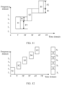
- signals S1 to S5 are respectively sent on different time-frequency resource elements.
- Bit sequences corresponding to an overlapping part that is of two signals and that is mapped in frequency domain have a same value and opposite symbols.
- the network device finally combines the signals S1 to S5 into a high-bandwidth signal, a value obtained after the bit sequences corresponding to the overlapping part in frequency domain are superimposed is 0.
- FIG. 13 is a schematic diagram of a positioning procedure to which an embodiment of this application is applicable.
- FIG. 13 lists only some steps in the positioning procedure. Detailed steps in the positioning procedure vary with different positioning scenarios and methods, and are not listed one by one herein.
- Step 1301 An AMF network element obtains a positioning service request, where the positioning service request is used to obtain information such as a positioning location of a terminal device.
- the positioning service request may be sent by an LCS entity, or may be sent by the terminal device. This is not limited in this embodiment of this application.
- Step 1302 The AMF network element forwards the positioning service request to an LMF network element.
- Step 1303a The LMF network element sends a positioning capability request message to the terminal device, where the positioning message is used to request a positioning capability of the terminal device.
- the positioning message may be sent by using an LTE positioning protocol (LTE positioning protocol, LPP) message.
- LTE positioning protocol LTE positioning protocol, LPP
- Step 1303b The terminal device sends a positioning capability response message to the LMF network element, where the positioning capability response message includes the positioning capability of the terminal device.
- the positioning capability refers to a positioning technology supported by the terminal device, for example, a capability of supporting global navigation satellite system (Global Navigation Satellite System, GNSS)-based positioning, a capability of supporting an observed time difference of arrival (Observed Time Difference of Arrival, OTDOA)-based positioning technology, and a capability of supporting sensor-based positioning.
- GNSS Global Navigation Satellite System
- OTDOA Observed Time Difference of Arrival
- Step 1304 The LMF network element sends a request message to a network device, to request related information of a positioning signal, for example, configuration information of the positioning signal.
- the positioning signal may be a signal sent by the terminal device by using the M time-frequency resource elements in the foregoing embodiment.
- Step 1305 The network device sends the configuration information of the positioning signal to the terminal device.
- the configuration information may indicate one or more of the following:
- the configuration information may further include other content. Details are not described herein.
- Step 1306 The network device sends the configuration information of the positioning signal to the LMF network element.
- step 1307 is performed, that is, the network device triggers the terminal device to send the positioning signal.
- Step 1308 The terminal device sends the positioning signal.
- the positioning signal may be the M signals described above. For details, refer to the descriptions in step 201 and step 202.
- Step 1309 The network device receives the positioning signal, and measures the positioning signal to obtain measurement information.
- the measurement information may include but is not limited to a reference signal time difference (Reference Signal Time Difference, RSTD), a round trip time (Round Trip Time, RTT), reference signal received power (Reference Signal Received Power, RSRP), reference signal received quality (Reference Signal Received Quality, RSRQ), and the like.
- RSTD Reference Signal Time Difference
- RTT Round Trip Time
- RSRP reference signal received power
- RSRQ Reference Signal Received Quality
- Step 1310 The network device sends the measurement information to the LMF network element.
- Step 1311 The LMF network element performs location calculation based on the measurement information, to obtain location information, and sends the location information to the AMF network element.
- the LMF network element specifically determines the location information based on the measurement information is not limited in this embodiment of this application.
- the LMF network element may further send the location information to the terminal device, the network device, or the like.
- the positioning procedure may further include another step. Details are not described herein.
- the network device or the terminal device may include a hardware structure and/or a software module, and implements the foregoing functions in a form of the hardware structure, the software module, or a combination of the hardware structure and the software module. Whether a function in the foregoing functions is performed by using the hardware structure, the software module, or the combination of the hardware structure and the software module depends on particular applications and design constraints of the technical solutions.
- division into the modules is an example and is merely logical function division, and may be other division in an actual implementation.
- functional modules in embodiments of this application may be integrated into one processor, or may exist alone physically, or two or more modules may be integrated into one module.
- the integrated module may be implemented in a form of hardware, or may be implemented in a form of a software functional module.
- an embodiment of this application further provides an apparatus 1400, configured to implement functions of the network device or the terminal device in the foregoing methods.
- the apparatus may be a software module or a chip system.
- the chip system may include a chip, or may include a chip and another discrete component.
- the apparatus 1400 may include a processing unit 1401 and a communication unit 1402.
- the communication unit may also be referred to as a transceiver unit, and may include a sending unit and/or a receiving unit, which are respectively configured to perform sending and receiving steps of the network device or the terminal device in the foregoing method embodiments.
- the communication unit may also be referred to as a transceiver, a transceiver machine, a transceiver apparatus, or the like.
- the processing unit may also be referred to as a processor, a processing board, a processing module, a processing apparatus, or the like.
- a component that is in the communication unit 1402 and that is configured to implement the receiving function may be considered as a receiving unit
- a component that is in the communication unit 1402 and that is configured to implement the sending function may be considered as a sending unit. That is, the communication unit 1402 includes the receiving unit and the sending unit.
- the communication unit sometimes may also be referred to as a transceiver machine, a transceiver, a transceiver circuit, or the like.
- the receiving unit sometimes may also be referred to as a receiver, a receiver machine, a receiver circuit, or the like.
- the sending unit sometimes may also be referred to as a transmitter, a transmitter machine, a transmitter circuit, or the like.
- the processing unit 1401 and the communication unit 1402 may further perform other functions.
- the processing unit 1401 and the communication unit 1402 may further perform other functions.
- FIG. 15 shows an apparatus 1500 according to an embodiment of this application.
- the apparatus shown in FIG. 15 may be an implementation of a hardware circuit of the apparatus shown in FIG. 14 .
- the communication apparatus is applicable to the flowchart shown above, and performs functions of the terminal device or the network device in the foregoing method embodiments. For ease of description, FIG. 15 shows only main components of the communication apparatus.
- the communication apparatus 1500 includes a processor 1510 and a communication interface 1520.
- the processor 1510 and the communication interface 1520 are coupled to each other.
- the communication interface 1520 may be a transceiver or an input/output interface.
- the communication apparatus 1500 may further include a memory 1530, configured to store instructions executed by the processor 1510, or input data required by the processor 1510 to run the instructions, or data generated after the processor 1510 runs the instructions.
- the processor 1510 is configured to implement a function of the processing unit 801
- the communication interface 1520 is configured to implement a function of the communication unit 802.
- the chip in the terminal device implements functions of the terminal device in the foregoing method embodiments.
- the chip in the terminal device receives information from another module (for example, a radio frequency module or an antenna) in the terminal device, where the information is sent by a network device to the terminal device.
- the chip in the terminal device sends information to another module (for example, a radio frequency module or an antenna) in the terminal device, where the information is sent by the terminal device to a network device.
- the chip in the network device implements functions of the network device in the foregoing method embodiments.
- the chip in the network device receives information from another module (for example, a radio frequency module or an antenna) in the network device, where the information is sent by a terminal device to the network device.
- the chip in the network device sends information to another module (for example, a radio frequency module or an antenna) in the network device, where the information is sent by the network device to a terminal device.
- the processor in embodiments of this application may be a central processing unit (Central Processing Unit, CPU), or may be another general-purpose processor, a digital signal processor (Digital Signal Processor, DSP), an application-specific integrated circuit (Application-Specific Integrated Circuit, ASIC), a field programmable gate array (Field Programmable Gate Array, FPGA), another programmable logic device, a transistor logic device, a hardware component, or any combination thereof.
- the general-purpose processor may be a microprocessor, any conventional processor, or the like.
- the processor may be a random access memory (Random Access Memory, RAM), a flash memory, a read-only memory (Read-Only Memory, ROM), a programmable read-only memory (Programmable ROM, PROM), an erasable programmable read-only memory (Erasable PROM, EPROM), an electrically erasable programmable read-only memory (Electrically EPROM, EEPROM), a register, a hard disk, a removable hard disk, a CD-ROM, or a storage medium in any other form well-known in the art.
- a storage medium is coupled to a processor, so that the processor can read information from the storage medium and write information into the storage medium.
- the storage medium may be a component of the processor.
- the processor and the storage medium may be located in an ASIC.
- the ASIC may be located in a network device or a terminal device.
- the processor and the storage medium may exist in the network device or the terminal device as discrete components.
- this application may be provided as a method, a system, or a computer program product. Therefore, this application may use a form of a hardware-only embodiment, a software-only embodiment, or an embodiment with a combination of software and hardware. In addition, this application may use a form of a computer program product that is implemented on one or more computer-usable storage media (including but not limited to a disk memory, an optical memory, and the like) that include computer-usable program code.
- a computer-usable storage media including but not limited to a disk memory, an optical memory, and the like
- These computer program instructions may be provided for a general-purpose computer, a dedicated computer, an embedded processor, or a processor of another programmable data processing device to generate a machine, so that the instructions executed by a computer or a processor of another programmable data processing device generate an apparatus for implementing a specified function in one or more procedures in the flowcharts and/or in one or more blocks in the block diagrams.
- the computer program instructions may alternatively be stored in a computer-readable memory that can guide a computer or another programmable data processing device to work in a specific manner, so that the instructions stored in the computer-readable memory generate an artifact that includes an instruction apparatus.
- the instruction apparatus implements a specified function in one or more procedures in the flowcharts and/or in one or more blocks in the block diagrams.
Landscapes
- Engineering & Computer Science (AREA)
- Signal Processing (AREA)
- Computer Networks & Wireless Communication (AREA)
- Databases & Information Systems (AREA)
- Mobile Radio Communication Systems (AREA)
Applications Claiming Priority (1)
| Application Number | Priority Date | Filing Date | Title |
|---|---|---|---|
| PCT/CN2020/128221 WO2022099524A1 (fr) | 2020-11-11 | 2020-11-11 | Procédés et appareils d'émission et de réception de signaux |
Publications (2)
| Publication Number | Publication Date |
|---|---|
| EP4228358A1 true EP4228358A1 (fr) | 2023-08-16 |
| EP4228358A4 EP4228358A4 (fr) | 2023-12-06 |
Family
ID=81601939
Family Applications (1)
| Application Number | Title | Priority Date | Filing Date |
|---|---|---|---|
| EP20961081.5A Pending EP4228358A4 (fr) | 2020-11-11 | 2020-11-11 | Procédés et appareils d'émission et de réception de signaux |
Country Status (5)
| Country | Link |
|---|---|
| US (1) | US20230284187A1 (fr) |
| EP (1) | EP4228358A4 (fr) |
| JP (2) | JP7816674B2 (fr) |
| CN (1) | CN116472761A (fr) |
| WO (1) | WO2022099524A1 (fr) |
Families Citing this family (2)
| Publication number | Priority date | Publication date | Assignee | Title |
|---|---|---|---|---|
| CN120264468A (zh) * | 2024-01-03 | 2025-07-04 | 华为技术有限公司 | 一种通信方法和装置 |
| CN119298939B (zh) * | 2024-12-12 | 2025-03-14 | 成都玖锦科技有限公司 | 一种基于双通道系统重叠频段的信号规划方法 |
Family Cites Families (20)
| Publication number | Priority date | Publication date | Assignee | Title |
|---|---|---|---|---|
| CN103036820B (zh) * | 2011-09-29 | 2017-08-01 | 锐迪科(重庆)微电子科技有限公司 | 一种基于参考信号的多小区信道估计方法和装置 |
| WO2013049962A1 (fr) | 2011-10-08 | 2013-04-11 | Huawei Technologies Co., Ltd. | Transmission de signal de référence de sondage |
| FR3017719B1 (fr) * | 2014-02-14 | 2016-03-04 | Thales Sa | Methode de correlation d'un signal de radio-navigation par satellite recu et dispositif de correlation mettant en oeuvre la methode |
| CN112087761B (zh) * | 2017-01-05 | 2023-10-03 | 华为技术有限公司 | 资源映射方法及用户设备 |
| US10856310B2 (en) * | 2017-02-03 | 2020-12-01 | Qualcomm Incorporated | Retuning in machine type communications |
| CN112600646B (zh) * | 2017-03-17 | 2022-03-29 | 上海朗帛通信技术有限公司 | 一种被用于无线通信的用户、基站中的方法和装置 |
| CN108632005B (zh) | 2017-03-24 | 2023-12-15 | 华为技术有限公司 | 一种参考信号传输方法、装置及系统 |
| MX2019005327A (es) | 2017-04-27 | 2019-08-12 | Lg Electronics Inc | Metodo de transmision de srs y terminal para el mismo. |
| CN108112076B (zh) * | 2017-05-05 | 2023-11-21 | 中兴通讯股份有限公司 | 配置上行信号的方法及装置 |
| CN109150444B (zh) * | 2017-06-16 | 2022-01-11 | 华为技术有限公司 | 资源单元的设置、传输方法及装置 |
| US11190320B2 (en) | 2017-06-16 | 2021-11-30 | Lg Electronics Inc. | Method for generating SRS sequence and terminal therefor |
| CN109586869B (zh) | 2017-09-29 | 2021-08-06 | 中国移动通信有限公司研究院 | Srs发送方法、相位差处理方法、通信设备及存储介质 |
| CN112152680A (zh) * | 2017-10-17 | 2020-12-29 | 上海朗帛通信技术有限公司 | 一种被用于无线通信的用户、基站中的方法和装置 |
| CN110034871B (zh) * | 2018-01-11 | 2020-07-31 | 上海朗帛通信技术有限公司 | 一种被用于无线通信的用户设备、基站中的方法和装置 |
| CN110401980B (zh) * | 2018-04-25 | 2022-12-27 | 上海朗帛通信技术有限公司 | 一种被用于无线通信的用户设备、基站中的方法和装置 |
| CN108762374A (zh) * | 2018-05-29 | 2018-11-06 | 西安微电子技术研究所 | 一种时钟管理电路及基于该电路的服务级芯片 |
| CN111865543B (zh) | 2019-04-30 | 2022-11-25 | 华为技术有限公司 | 一种信号传输方法及装置 |
| US11509372B2 (en) | 2019-05-03 | 2022-11-22 | Qualcomm Incorporated | Capability information for sounding reference signal improvements |
| WO2020247184A1 (fr) * | 2019-06-07 | 2020-12-10 | Applied Materials, Inc. | Solutions de chargement de résine photosensible pour la fabrication d'optiques plates |
| CN110336587B (zh) * | 2019-07-16 | 2021-10-22 | 电子科技大学 | 一种多跳频信号侦察中获取组合时频分布的方法 |
-
2020
- 2020-11-11 CN CN202080106930.9A patent/CN116472761A/zh active Pending
- 2020-11-11 WO PCT/CN2020/128221 patent/WO2022099524A1/fr not_active Ceased
- 2020-11-11 EP EP20961081.5A patent/EP4228358A4/fr active Pending
- 2020-11-11 JP JP2023528280A patent/JP7816674B2/ja active Active
-
2023
- 2023-05-10 US US18/314,963 patent/US20230284187A1/en active Pending
-
2025
- 2025-11-07 JP JP2025187948A patent/JP2026048633A/ja active Pending
Also Published As
| Publication number | Publication date |
|---|---|
| US20230284187A1 (en) | 2023-09-07 |
| JP2026048633A (ja) | 2026-03-17 |
| JP2023549492A (ja) | 2023-11-27 |
| CN116472761A (zh) | 2023-07-21 |
| EP4228358A4 (fr) | 2023-12-06 |
| WO2022099524A1 (fr) | 2022-05-19 |
| JP7816674B2 (ja) | 2026-02-18 |
Similar Documents
| Publication | Publication Date | Title |
|---|---|---|
| JP7266040B2 (ja) | 測位方法及び関連機器 | |
| US20210091905A1 (en) | Method for configuring positioning reference signal in nr system, method for receiving positioning reference signal in nr system, and device | |
| EP3979670B1 (fr) | Procédé et dispositif pour déterminer des informations | |
| US11438127B2 (en) | Measurement gap determination method, user equipment, and network side device | |
| EP4229801B1 (fr) | Positionnement d'équipement utilisateur | |
| US20230275681A1 (en) | Signal sending method, signal receiving method, and apparatus | |
| CN116963169A (zh) | 一种通信方法及设备 | |
| US12604303B2 (en) | Signal transmission method and apparatus | |
| US20230284187A1 (en) | Signal sending method, signal receiving method, and apparatus | |
| CN111936879A (zh) | 用于导航和定位信号的分离的正交频分复用 | |
| EP4518360A1 (fr) | Procédé et appareil de transmission d'informations, et procédé et appareil de positionnement de phase de porteuse | |
| US20240319352A1 (en) | Carrier phase positioning techniques | |
| CN112566010A (zh) | 一种信号发送、接收方法、网络设备及终端设备 | |
| WO2024033195A1 (fr) | Technique de positionnement de phase de porteuse | |
| CN119024390A (zh) | 测量方法及装置、计算机可读存储介质 | |
| CN120239091A (zh) | 感知处理方法、装置、设备及可读存储介质 |
Legal Events
| Date | Code | Title | Description |
|---|---|---|---|
| STAA | Information on the status of an ep patent application or granted ep patent |
Free format text: STATUS: THE INTERNATIONAL PUBLICATION HAS BEEN MADE |
|
| PUAI | Public reference made under article 153(3) epc to a published international application that has entered the european phase |
Free format text: ORIGINAL CODE: 0009012 |
|
| STAA | Information on the status of an ep patent application or granted ep patent |
Free format text: STATUS: REQUEST FOR EXAMINATION WAS MADE |
|
| 17P | Request for examination filed |
Effective date: 20230512 |
|
| AK | Designated contracting states |
Kind code of ref document: A1 Designated state(s): AL AT BE BG CH CY CZ DE DK EE ES FI FR GB GR HR HU IE IS IT LI LT LU LV MC MK MT NL NO PL PT RO RS SE SI SK SM TR |
|
| REG | Reference to a national code |
Ref country code: DE Ref legal event code: R079 Free format text: PREVIOUS MAIN CLASS: H04W0072040000 Ipc: H04L0005000000 |
|
| A4 | Supplementary search report drawn up and despatched |
Effective date: 20231108 |
|
| RIC1 | Information provided on ipc code assigned before grant |
Ipc: H04W 64/00 20090101ALN20231102BHEP Ipc: H04W 72/04 20230101ALI20231102BHEP Ipc: H04L 5/00 20060101AFI20231102BHEP |
|
| DAV | Request for validation of the european patent (deleted) | ||
| DAX | Request for extension of the european patent (deleted) |