EP4228936B1 - Bremssystem - Google Patents
Bremssystem Download PDFInfo
- Publication number
- EP4228936B1 EP4228936B1 EP21798314.7A EP21798314A EP4228936B1 EP 4228936 B1 EP4228936 B1 EP 4228936B1 EP 21798314 A EP21798314 A EP 21798314A EP 4228936 B1 EP4228936 B1 EP 4228936B1
- Authority
- EP
- European Patent Office
- Prior art keywords
- cam
- hydraulic cylinder
- hydraulic
- valve
- piston
- Prior art date
- Legal status (The legal status is an assumption and is not a legal conclusion. Google has not performed a legal analysis and makes no representation as to the accuracy of the status listed.)
- Active
Links
Images









Classifications
-
- B—PERFORMING OPERATIONS; TRANSPORTING
- B60—VEHICLES IN GENERAL
- B60T—VEHICLE BRAKE CONTROL SYSTEMS OR PARTS THEREOF; BRAKE CONTROL SYSTEMS OR PARTS THEREOF, IN GENERAL; ARRANGEMENT OF BRAKING ELEMENTS ON VEHICLES IN GENERAL; PORTABLE DEVICES FOR PREVENTING UNWANTED MOVEMENT OF VEHICLES; VEHICLE MODIFICATIONS TO FACILITATE COOLING OF BRAKES
- B60T1/00—Arrangements of braking elements, i.e. of those parts where braking effect occurs specially for vehicles
- B60T1/02—Arrangements of braking elements, i.e. of those parts where braking effect occurs specially for vehicles acting by retarding wheels
-
- B—PERFORMING OPERATIONS; TRANSPORTING
- B60—VEHICLES IN GENERAL
- B60T—VEHICLE BRAKE CONTROL SYSTEMS OR PARTS THEREOF; BRAKE CONTROL SYSTEMS OR PARTS THEREOF, IN GENERAL; ARRANGEMENT OF BRAKING ELEMENTS ON VEHICLES IN GENERAL; PORTABLE DEVICES FOR PREVENTING UNWANTED MOVEMENT OF VEHICLES; VEHICLE MODIFICATIONS TO FACILITATE COOLING OF BRAKES
- B60T1/00—Arrangements of braking elements, i.e. of those parts where braking effect occurs specially for vehicles
- B60T1/005—Arrangements of braking elements, i.e. of those parts where braking effect occurs specially for vehicles by locking of wheel or transmission rotation
-
- B—PERFORMING OPERATIONS; TRANSPORTING
- B60—VEHICLES IN GENERAL
- B60T—VEHICLE BRAKE CONTROL SYSTEMS OR PARTS THEREOF; BRAKE CONTROL SYSTEMS OR PARTS THEREOF, IN GENERAL; ARRANGEMENT OF BRAKING ELEMENTS ON VEHICLES IN GENERAL; PORTABLE DEVICES FOR PREVENTING UNWANTED MOVEMENT OF VEHICLES; VEHICLE MODIFICATIONS TO FACILITATE COOLING OF BRAKES
- B60T1/00—Arrangements of braking elements, i.e. of those parts where braking effect occurs specially for vehicles
- B60T1/02—Arrangements of braking elements, i.e. of those parts where braking effect occurs specially for vehicles acting by retarding wheels
- B60T1/06—Arrangements of braking elements, i.e. of those parts where braking effect occurs specially for vehicles acting by retarding wheels acting otherwise than on tread, e.g. employing rim, drum, disc, or transmission or on double wheels
-
- B—PERFORMING OPERATIONS; TRANSPORTING
- B60—VEHICLES IN GENERAL
- B60T—VEHICLE BRAKE CONTROL SYSTEMS OR PARTS THEREOF; BRAKE CONTROL SYSTEMS OR PARTS THEREOF, IN GENERAL; ARRANGEMENT OF BRAKING ELEMENTS ON VEHICLES IN GENERAL; PORTABLE DEVICES FOR PREVENTING UNWANTED MOVEMENT OF VEHICLES; VEHICLE MODIFICATIONS TO FACILITATE COOLING OF BRAKES
- B60T1/00—Arrangements of braking elements, i.e. of those parts where braking effect occurs specially for vehicles
- B60T1/02—Arrangements of braking elements, i.e. of those parts where braking effect occurs specially for vehicles acting by retarding wheels
- B60T1/06—Arrangements of braking elements, i.e. of those parts where braking effect occurs specially for vehicles acting by retarding wheels acting otherwise than on tread, e.g. employing rim, drum, disc, or transmission or on double wheels
- B60T1/062—Arrangements of braking elements, i.e. of those parts where braking effect occurs specially for vehicles acting by retarding wheels acting otherwise than on tread, e.g. employing rim, drum, disc, or transmission or on double wheels acting on transmission parts
-
- B—PERFORMING OPERATIONS; TRANSPORTING
- B60—VEHICLES IN GENERAL
- B60T—VEHICLE BRAKE CONTROL SYSTEMS OR PARTS THEREOF; BRAKE CONTROL SYSTEMS OR PARTS THEREOF, IN GENERAL; ARRANGEMENT OF BRAKING ELEMENTS ON VEHICLES IN GENERAL; PORTABLE DEVICES FOR PREVENTING UNWANTED MOVEMENT OF VEHICLES; VEHICLE MODIFICATIONS TO FACILITATE COOLING OF BRAKES
- B60T1/00—Arrangements of braking elements, i.e. of those parts where braking effect occurs specially for vehicles
- B60T1/02—Arrangements of braking elements, i.e. of those parts where braking effect occurs specially for vehicles acting by retarding wheels
- B60T1/08—Arrangements of braking elements, i.e. of those parts where braking effect occurs specially for vehicles acting by retarding wheels using fluid or powdered medium
- B60T1/093—Arrangements of braking elements, i.e. of those parts where braking effect occurs specially for vehicles acting by retarding wheels using fluid or powdered medium in hydrostatic, i.e. positive displacement, retarders
-
- B—PERFORMING OPERATIONS; TRANSPORTING
- B60—VEHICLES IN GENERAL
- B60T—VEHICLE BRAKE CONTROL SYSTEMS OR PARTS THEREOF; BRAKE CONTROL SYSTEMS OR PARTS THEREOF, IN GENERAL; ARRANGEMENT OF BRAKING ELEMENTS ON VEHICLES IN GENERAL; PORTABLE DEVICES FOR PREVENTING UNWANTED MOVEMENT OF VEHICLES; VEHICLE MODIFICATIONS TO FACILITATE COOLING OF BRAKES
- B60T1/00—Arrangements of braking elements, i.e. of those parts where braking effect occurs specially for vehicles
- B60T1/02—Arrangements of braking elements, i.e. of those parts where braking effect occurs specially for vehicles acting by retarding wheels
- B60T1/10—Arrangements of braking elements, i.e. of those parts where braking effect occurs specially for vehicles acting by retarding wheels by utilising wheel movement for accumulating energy, e.g. driving air compressors
-
- B—PERFORMING OPERATIONS; TRANSPORTING
- B60—VEHICLES IN GENERAL
- B60T—VEHICLE BRAKE CONTROL SYSTEMS OR PARTS THEREOF; BRAKE CONTROL SYSTEMS OR PARTS THEREOF, IN GENERAL; ARRANGEMENT OF BRAKING ELEMENTS ON VEHICLES IN GENERAL; PORTABLE DEVICES FOR PREVENTING UNWANTED MOVEMENT OF VEHICLES; VEHICLE MODIFICATIONS TO FACILITATE COOLING OF BRAKES
- B60T10/00—Control or regulation for continuous braking making use of fluid or powdered medium, e.g. for use when descending a long slope
- B60T10/04—Control or regulation for continuous braking making use of fluid or powdered medium, e.g. for use when descending a long slope with hydrostatic brake
-
- B—PERFORMING OPERATIONS; TRANSPORTING
- B60—VEHICLES IN GENERAL
- B60T—VEHICLE BRAKE CONTROL SYSTEMS OR PARTS THEREOF; BRAKE CONTROL SYSTEMS OR PARTS THEREOF, IN GENERAL; ARRANGEMENT OF BRAKING ELEMENTS ON VEHICLES IN GENERAL; PORTABLE DEVICES FOR PREVENTING UNWANTED MOVEMENT OF VEHICLES; VEHICLE MODIFICATIONS TO FACILITATE COOLING OF BRAKES
- B60T13/00—Transmitting braking action from initiating means to ultimate brake actuator with power assistance or drive; Brake systems incorporating such transmitting means, e.g. air-pressure brake systems
- B60T13/10—Transmitting braking action from initiating means to ultimate brake actuator with power assistance or drive; Brake systems incorporating such transmitting means, e.g. air-pressure brake systems with fluid assistance, drive, or release
- B60T13/12—Transmitting braking action from initiating means to ultimate brake actuator with power assistance or drive; Brake systems incorporating such transmitting means, e.g. air-pressure brake systems with fluid assistance, drive, or release the fluid being liquid
- B60T13/14—Transmitting braking action from initiating means to ultimate brake actuator with power assistance or drive; Brake systems incorporating such transmitting means, e.g. air-pressure brake systems with fluid assistance, drive, or release the fluid being liquid using accumulators or reservoirs fed by pumps
- B60T13/142—Systems with master cylinder
-
- B—PERFORMING OPERATIONS; TRANSPORTING
- B60—VEHICLES IN GENERAL
- B60T—VEHICLE BRAKE CONTROL SYSTEMS OR PARTS THEREOF; BRAKE CONTROL SYSTEMS OR PARTS THEREOF, IN GENERAL; ARRANGEMENT OF BRAKING ELEMENTS ON VEHICLES IN GENERAL; PORTABLE DEVICES FOR PREVENTING UNWANTED MOVEMENT OF VEHICLES; VEHICLE MODIFICATIONS TO FACILITATE COOLING OF BRAKES
- B60T13/00—Transmitting braking action from initiating means to ultimate brake actuator with power assistance or drive; Brake systems incorporating such transmitting means, e.g. air-pressure brake systems
- B60T13/10—Transmitting braking action from initiating means to ultimate brake actuator with power assistance or drive; Brake systems incorporating such transmitting means, e.g. air-pressure brake systems with fluid assistance, drive, or release
- B60T13/58—Combined or convertible systems
- B60T13/585—Combined or convertible systems comprising friction brakes and retarders
- B60T13/586—Combined or convertible systems comprising friction brakes and retarders the retarders being of the electric type
-
- B—PERFORMING OPERATIONS; TRANSPORTING
- B60—VEHICLES IN GENERAL
- B60T—VEHICLE BRAKE CONTROL SYSTEMS OR PARTS THEREOF; BRAKE CONTROL SYSTEMS OR PARTS THEREOF, IN GENERAL; ARRANGEMENT OF BRAKING ELEMENTS ON VEHICLES IN GENERAL; PORTABLE DEVICES FOR PREVENTING UNWANTED MOVEMENT OF VEHICLES; VEHICLE MODIFICATIONS TO FACILITATE COOLING OF BRAKES
- B60T13/00—Transmitting braking action from initiating means to ultimate brake actuator with power assistance or drive; Brake systems incorporating such transmitting means, e.g. air-pressure brake systems
- B60T13/10—Transmitting braking action from initiating means to ultimate brake actuator with power assistance or drive; Brake systems incorporating such transmitting means, e.g. air-pressure brake systems with fluid assistance, drive, or release
- B60T13/66—Electrical control in fluid-pressure brake systems
- B60T13/68—Electrical control in fluid-pressure brake systems by electrically-controlled valves
- B60T13/686—Electrical control in fluid-pressure brake systems by electrically-controlled valves in hydraulic systems or parts thereof
-
- B—PERFORMING OPERATIONS; TRANSPORTING
- B60—VEHICLES IN GENERAL
- B60T—VEHICLE BRAKE CONTROL SYSTEMS OR PARTS THEREOF; BRAKE CONTROL SYSTEMS OR PARTS THEREOF, IN GENERAL; ARRANGEMENT OF BRAKING ELEMENTS ON VEHICLES IN GENERAL; PORTABLE DEVICES FOR PREVENTING UNWANTED MOVEMENT OF VEHICLES; VEHICLE MODIFICATIONS TO FACILITATE COOLING OF BRAKES
- B60T17/00—Component parts, details, or accessories of power brake systems not covered by groups B60T8/00, B60T13/00 or B60T15/00, or presenting other characteristic features
-
- B—PERFORMING OPERATIONS; TRANSPORTING
- B60—VEHICLES IN GENERAL
- B60T—VEHICLE BRAKE CONTROL SYSTEMS OR PARTS THEREOF; BRAKE CONTROL SYSTEMS OR PARTS THEREOF, IN GENERAL; ARRANGEMENT OF BRAKING ELEMENTS ON VEHICLES IN GENERAL; PORTABLE DEVICES FOR PREVENTING UNWANTED MOVEMENT OF VEHICLES; VEHICLE MODIFICATIONS TO FACILITATE COOLING OF BRAKES
- B60T7/00—Brake-action initiating means
- B60T7/02—Brake-action initiating means for personal initiation
- B60T7/04—Brake-action initiating means for personal initiation foot actuated
-
- B—PERFORMING OPERATIONS; TRANSPORTING
- B60—VEHICLES IN GENERAL
- B60T—VEHICLE BRAKE CONTROL SYSTEMS OR PARTS THEREOF; BRAKE CONTROL SYSTEMS OR PARTS THEREOF, IN GENERAL; ARRANGEMENT OF BRAKING ELEMENTS ON VEHICLES IN GENERAL; PORTABLE DEVICES FOR PREVENTING UNWANTED MOVEMENT OF VEHICLES; VEHICLE MODIFICATIONS TO FACILITATE COOLING OF BRAKES
- B60T7/00—Brake-action initiating means
- B60T7/02—Brake-action initiating means for personal initiation
- B60T7/08—Brake-action initiating means for personal initiation hand actuated
-
- F—MECHANICAL ENGINEERING; LIGHTING; HEATING; WEAPONS; BLASTING
- F16—ENGINEERING ELEMENTS AND UNITS; GENERAL MEASURES FOR PRODUCING AND MAINTAINING EFFECTIVE FUNCTIONING OF MACHINES OR INSTALLATIONS; THERMAL INSULATION IN GENERAL
- F16D—COUPLINGS FOR TRANSMITTING ROTATION; CLUTCHES; BRAKES
- F16D57/00—Liquid-resistance brakes; Brakes using the internal friction of fluids or fluid-like media, e.g. powders
- F16D57/06—Liquid-resistance brakes; Brakes using the internal friction of fluids or fluid-like media, e.g. powders comprising a pump circulating fluid, braking being effected by throttling of the circulation
-
- F—MECHANICAL ENGINEERING; LIGHTING; HEATING; WEAPONS; BLASTING
- F16—ENGINEERING ELEMENTS AND UNITS; GENERAL MEASURES FOR PRODUCING AND MAINTAINING EFFECTIVE FUNCTIONING OF MACHINES OR INSTALLATIONS; THERMAL INSULATION IN GENERAL
- F16D—COUPLINGS FOR TRANSMITTING ROTATION; CLUTCHES; BRAKES
- F16D61/00—Brakes with means for making the energy absorbed available for use
-
- B—PERFORMING OPERATIONS; TRANSPORTING
- B60—VEHICLES IN GENERAL
- B60H—ARRANGEMENTS OF HEATING, COOLING, VENTILATING OR OTHER AIR-TREATING DEVICES SPECIALLY ADAPTED FOR PASSENGER OR GOODS SPACES OF VEHICLES
- B60H1/00—Heating, cooling or ventilating devices
- B60H1/32—Cooling devices
- B60H1/3201—Cooling devices using absorption or adsorption
- B60H1/32011—Cooling devices using absorption or adsorption using absorption, e.g. using Li-Br and water
-
- B—PERFORMING OPERATIONS; TRANSPORTING
- B60—VEHICLES IN GENERAL
- B60T—VEHICLE BRAKE CONTROL SYSTEMS OR PARTS THEREOF; BRAKE CONTROL SYSTEMS OR PARTS THEREOF, IN GENERAL; ARRANGEMENT OF BRAKING ELEMENTS ON VEHICLES IN GENERAL; PORTABLE DEVICES FOR PREVENTING UNWANTED MOVEMENT OF VEHICLES; VEHICLE MODIFICATIONS TO FACILITATE COOLING OF BRAKES
- B60T2270/00—Further aspects of brake control systems not otherwise provided for
- B60T2270/40—Failsafe aspects of brake control systems
- B60T2270/402—Back-up
-
- B—PERFORMING OPERATIONS; TRANSPORTING
- B60—VEHICLES IN GENERAL
- B60T—VEHICLE BRAKE CONTROL SYSTEMS OR PARTS THEREOF; BRAKE CONTROL SYSTEMS OR PARTS THEREOF, IN GENERAL; ARRANGEMENT OF BRAKING ELEMENTS ON VEHICLES IN GENERAL; PORTABLE DEVICES FOR PREVENTING UNWANTED MOVEMENT OF VEHICLES; VEHICLE MODIFICATIONS TO FACILITATE COOLING OF BRAKES
- B60T2270/00—Further aspects of brake control systems not otherwise provided for
- B60T2270/40—Failsafe aspects of brake control systems
- B60T2270/413—Plausibility monitoring, cross check, redundancy
-
- B—PERFORMING OPERATIONS; TRANSPORTING
- B60—VEHICLES IN GENERAL
- B60T—VEHICLE BRAKE CONTROL SYSTEMS OR PARTS THEREOF; BRAKE CONTROL SYSTEMS OR PARTS THEREOF, IN GENERAL; ARRANGEMENT OF BRAKING ELEMENTS ON VEHICLES IN GENERAL; PORTABLE DEVICES FOR PREVENTING UNWANTED MOVEMENT OF VEHICLES; VEHICLE MODIFICATIONS TO FACILITATE COOLING OF BRAKES
- B60T2270/00—Further aspects of brake control systems not otherwise provided for
- B60T2270/60—Regenerative braking
-
- F—MECHANICAL ENGINEERING; LIGHTING; HEATING; WEAPONS; BLASTING
- F16—ENGINEERING ELEMENTS AND UNITS; GENERAL MEASURES FOR PRODUCING AND MAINTAINING EFFECTIVE FUNCTIONING OF MACHINES OR INSTALLATIONS; THERMAL INSULATION IN GENERAL
- F16D—COUPLINGS FOR TRANSMITTING ROTATION; CLUTCHES; BRAKES
- F16D2125/00—Components of actuators
- F16D2125/18—Mechanical mechanisms
- F16D2125/20—Mechanical mechanisms converting rotation to linear movement or vice versa
- F16D2125/22—Mechanical mechanisms converting rotation to linear movement or vice versa acting transversely to the axis of rotation
- F16D2125/28—Cams; Levers with cams
- F16D2125/30—Cams; Levers with cams acting on two or more cam followers, e.g. S-cams
Definitions
- the invention relates to a braking system for a vehicle.
- the invention relates to a hydraulic mechanical braking system that does not use conventional abrasive materials such as brake pads, brake shoes, brake discs and brake drums and therefore does not produce any particulates (brake dust).
- the system does not use conventional brake callipers or slave cylinders.
- Another advantage of the braking system is that it is not affected by wet weather (rain) as the system is totally sealed.
- the braking system of the present invention also includes an energy recovery system harnessing energy from the flowing hydraulic fluid for other purposes.
- DE 37 26 318 A1 describes that, on a shaft to be braked, an eccentric is fitted so that it cannot rotate. Two pistons, which run in two opposing cylinders, bear on the said eccentric with their rear side. Due to the eccentric movement, the pistons are set in a linear motion.
- US 2005/127745 A1 describes a braking system comprised of a rotor, a plurality of actuators, a brake control unit and a by-pass valve. When in a brake-on mode of operation, the brake control unit effects braking by restricting the flow of a working fluid that is pumped in and out by each of the plurality of actuators as they engage the rotating rotor.
- US 2640563 A describes a hydraulic brake of a type that restrains the rotation of a rotating body by the throttling action of a controlled valve on fluid circulated by the motion of pistons.
- the present invention provides a braking system for a vehicle comprising:
- a cam may be attached to a transmission system as a powered output member (transmission shaft) which advantageously engages on demand to at least two hydraulic cylinder assemblies (single acting or double acting cylinders), with a cam follower (bearing, roller follower, etc.) attached on the end of each hydraulic cylinder assembly (ideally the cylinders are of equal size and are used in pairs).
- the at least two hydraulic cylinders may be placed radially 180° apart (such that longitudinally the hydraulic cylinder assemblies centre lines bisects the cam centre of rotation) and working in opposition (i.e. when one hydraulic cylinder assembly may be fully extended the other hydraulic cylinder assembly may be fully contracted) about the cam along the cam face with the cam follower (roller followers) attached to the hydraulic cylinder assemblies being in contact (engaged) with the cam face.
- the cam may be in the middle between the at least two hydraulic cylinder assemblies.
- the cam rotates, this may be in either direction, bidirectional rotary motion (i.e. clockwise and anti-clockwise), the hydraulic cylinder assemblies are actuated enabling bi-linear motion (reciprocation) of the engaged hydraulic cylinder assemblies to take place.
- a cylinder (body tubes) of the at least two hydraulic cylinder assemblies may be fixed relative to the cam, thus the each cam follower (bearings) will be attached to the end of the piston (rods).
- the piston (rods) may be fixed relative to the cam and the cam follower (bearings) are attached to the ends of the cylinder (body tubes) of the each hydraulic cylinder assemblies.
- the hydraulic cylinder assemblies reciprocate and hydraulic fluid (oil, lubricating fluid, fluid with a low viscosity etc.) within the hydraulic cylinder assemblies is pumped into a hydraulic circuit (network of system pipes).
- the hydraulic circuit is arranged so that the hydraulic fluid to flow from one hydraulic cylinder assembly to the other through a series of one way valves and fluid (oil) control valves.
- a master brake valve controls the fluid (e.g. oil) flow in the hydraulic circuit.
- the master brake valve is actuatable to restrict the flow of fluid to a desired level or degree. This restriction of fluid flow from one hydraulic cylinder assembly to the opposing second hydraulic cylinder assembly imposes a force on the cam to cause the cam to retard it's rotational motion. Thus a braking force is achieved of the transmission shaft (output).
- Within the hydraulic circuit (C) (the network of system pipes) may also include a secondary brake valve (hand brake valve).
- a secondary brake valve (hand brake valve).
- the braking system may comprise a separate second hydraulic circuit (high pressure hydraulic system) for the engagement and disengagement of the double acting hydraulic cylinders may be incorporated.
- the second hydraulic circuit may be arranged to be engageable or disengageable by the actuation of the master brake valve and/or the secondary brake valve (brake pedal or hand brake of the vehicle concerned, respectively).
- the engagement and disengagement system may comprise of a hydraulic pump, a pressure reservoir, a pressure regulator, at least two single acting hydraulic cylinders, a second hydraulic circuit (second network of pipes), at least one one-way valves, an engagement valve, a disengagement valve, oil, and an oil sump.
- the engagement and disengagement system may be configured that when the brake pedal is moved by the smallest degree the system is activated and each cam follower (roller followers), attached to the at least two hydraulic cylinder assemblies, engages with the cam.
- the present invention is configured to provide a braking force on the cam when the user input is provided (brake pedal or handbrake) past the point where the roller followers are engaged with the cam, therefore a brake master cylinder is actuated.
- the actuation of the brake master cylinder in turn may actuate the master brake valve which may cause a restriction to the oil flow.
- the restriction in oil flow between the hydraulic cylinder assemblies results in achieving a proportional braking force to the degree of movement of the brake pedal.
- the engagement and disengagement system deploys at least two single acting hydraulic cylinders which may each be fixed firmly by a mechanical means to a transmission housing along the longitudinal centre line of the double acting hydraulic cylinders.
- the actuation of the secondary brake valve or master brake valve by the user input or the secondary user input, respectively, may engage the hydraulic cylinder assemblies with the cam and shuts off the oil flow between the hydraulic cylinder assemblies taking place.
- the system is hydraulically locked and the cam cannot rotate.
- the present invention relates to a hydraulic mechanical braking system with an anti-lock braking system (ABS).
- ABS anti-lock braking system
- the general features and functioning of the braking system are described below with reference to Fig.s 1-22 .
- the specific features of the present invention are described with reference to Fig.s 23 and 24 .
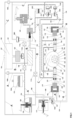
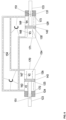
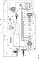
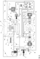
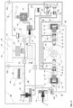
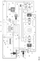
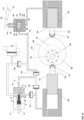
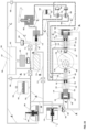
- Fig. 1 shows a schematic diagram of one example of a hydraulic mechanical braking system.
- the system comprises of 3 (three) independent hydraulic circuits each having their own network of pipes (A, B, and C) which may be inter-connected by shut off valves for additional service functionalities. It is assumed that the three hydraulic circuits are full of fluid (oil, hydraulic fluid, fluid with a low viscosity, lubricant fluid) (158) and fully bled i.e. all air has been removed from the hydraulic circuits.
- fluid oil, hydraulic fluid, fluid with a low viscosity, lubricant fluid
- the braking system comprises a cam (128).
- the cam (128) is a 'heart shaped' cam (128).
- the cam (128) may be coupled to a shaft, for example, the cam (128) may be coupled to a power transmission system (e.g.: a transaxle gearbox) by a splined bore (139) as a powered output member (transmission shaft or transmission output).
- the cam (128) may be coupled to an unpowered part of a trailing axle or trailing wheel system.
- the cam (128) is rotating with an arrow indicating its direction of rotation (117). In the example of Fig.1 the cam is rotating clockwise.
- the cam (128) is shown to have a centre of rotation (140) and a cam face (196).
- the cam face (196) interfaces with at least two cam followers (bearings, roller followers, etc.) (127).
- the cam followers (127) are alternatively roller followers.
- the braking system further comprises at least two hydraulic cylinder assemblies (126, 129).
- Each hydraulic cylinder assembly (126, 129) comprises a cylinder (126, 129) and a piston (125, 130) configured to reciprocate relative to one another.
- Each cam follower is attached to either the cylinder or the piston and arranged to contact the cam, whereby rotation of the cam causes the cam follower and the cylinder or the piston to which it is attached to reciprocate relative to the other of the piston or the cylinder.
- the cam followers may be attached to the cylinders via a clevis.
- the hydraulic cylinder assemblies (126 and 129) may be positioned such that their longitudinal centre lines (190) bi-sects the cam centre of rotation (140) ensuring that the cam followers (127) arranged perpendicular to the cam face (196) at the point of contact or engagement.
- the hydraulic cylinder assemblies (126 and 129) may be located 180° apart about the cam (128).
- the hydraulic cylinder assemblies (126 and 129) are connected to each other via a network of pipes (C) forming a hydraulic circuit.
- the network of pipes (C) may comprise a plurality of one way valves (104C, 204C, 110C, 210C).
- a four-way directional control valve system is provided comprising two one way valves (104C, 204C) which are shown in the closed position and two one way valves (110C and 210C) which are shown in the open position.
- the hydraulic circuit (C) of the braking system may further comprise a secondary brake valve (assembly) (105) (which is preferably a hand brake of a vehicle).
- the secondary brake valve (105) is shown in the open position, i.e. the hand brake (105) is in the off position and the master brake valve (assembly) (113) is in a partially open position.
- the hydraulic circuit (C) may further comprise a pressure reservoir (102C), wherein the pressure reservoir (102C) is fully pressurized to a pre-set desired pressure for an operational state of the braking system.
- a pressure regulator valve (100C) may be provided to ensure the desired system pressure is not exceeded.
- Another one way valve (188C) is in the closed position, and a shut off valve (111C) is in the closed position.
- the first hydraulic cylinder assembly (126) shown on the left in Figure 1 comprises a piston (125), a cylinder and a cam follower (127). Additionally, the first hydraulic cylinder assembly may further comprise a piston rod (123) and a cylinder gland (124). The hydraulic cylinder assembly (126) may be located in a guide in the transmission housing (122) which may allow for the hydraulic cylinder assembly (126) body tube (cylinder) with its inlet/out pipes to slide freely longitudinally along its line of longitudinal centre line (190). Similarly the second hydraulic cylinder assembly (129) shown on the right in Figure 1 comprises a piston (130), a cylinder and a cam follower (127).
- the second hydraulic assembly may further comprise a piston rod (133) and a cylinder gland (131) is located in a guide in the transmission housing (132).
- the guide of the transmission housing (132) may allow for the hydraulic cylinder assembly (129) cylinder (body tube) with its inlet/out pipes to slide freely longitudinally along its line of longitudinal centre line (190).
- the piston rod (123) of the first hydraulic cylinder assembly (126) may be firmly or securely attached at one end to the piston (125) within the hydraulic cylinder assembly (126) and the other end may be firmly or securely attached to a single acting piston (119).
- the single acting piston (119) is part of a single acting hydraulic cylinder (120).
- the piston rod (133) of the second hydraulic cylinder assembly (129) may be firmly or securely attached at one end to a piston (130) within the hydraulic cylinder assembly (129) and the other end may be firmly or securely attached to a piston (134) which may be part of another single acting hydraulic cylinder (136).
- the single acting hydraulic cylinders (120 and 136) may be of identical dimensions and may be in the fully extended position and be connected to each other through a network of pipes (A) forming another hydraulic circuit, a second hydraulic circuit (A). Additionally, the network of pipes (A) may comprise at least one one-way valve closed (104A) in the closed position, adjacent to an engagement valve assembly (115) in the closed position, a disengagement valve assembly (106) in the closed position and a pressure reservoir (102A) fully pressurized to pre-set desired pressure.
- this reservoir (102A) may be substantial so that it may holds a quantity of oil under the desired pressure to activate the single acting hydraulic cylinders (120, 136) at times when the hydraulic pump may be switched off and, further to compensate for changes in oil volume due to variation in temperature.
- the network of pipes (A) may further comprise a shut off valve (107) in the open position, a one way valve (110A) in the open position, a shut off valve (111A) in the closed position, a hydraulic pump (103) which is active and working providing the desired working system pressure, an oil sump (101) and a pressure regulator valve (100A) to ensure the desired system pressure is not exceeded.
- a third hydraulic circuit (network of pipes) (B) may inter-connect the brake master cylinder (112), the sump (101), the master brake valve (113) and the shut off valve (111A) in the closed position.
- the dotted circle/s (108) indicate network pipes crossing over each other at right angles and not connected in the relevant figures (this is to only show where the pipes do not connect and it is not a structural requirement of the pipes to cross at 90 degrees).
- the small arrows (154) in the network of pipes indicate the direction of oil flow in the relevant figures.
- the circle (118) indicates the circular path of maximum stroke of the cam (128) and the circle (137) indicates the circular path of minimum stroke of the cam (128) as shown in figure 1 .
- Small arrows in a parallel row (155) indicates a pressure head, as shown in figure 1 .
- the cam of the braking system may further comprise a plurality of tapped holes (138) of which there may be 8 (eight) on the same Pitch Circle Diameter (PCD) equally spaced and, a counterbore (141) both may be used for the location and fixing of a drive shaft from a driven wheel.
- PCD Pitch Circle Diameter
- the cam (128) is shown in figure 1 , rotating in a clockwise direction with its apex (199) vertically at the top and, the indent (198) vertically below diametrically opposed both on a central axis passing through the cam centre of rotation (140).
- the cam followers (127) attached to the hydraulic cylinders (126,129) are in contact (engaged) with the cam face (196).
- the cam followers (127) are shown in figure 1 to be attached to the cylinder and arranged to contact the cam (128), whereby rotation of the cam (128) causes the cam follower (127) and the cylinder to which it is attached to reciprocate relative to the piston (125, 130).
- Both hydraulic cylinder assemblies (126, 129) are both in a mid-stroke position, i.e.: half contracted and half extended.
- the transmission housing guides (122, 132) may act as mechanical stops for the pistons (119, 134), this is to ensure the pistons (119, 134) cannot extend any further.
- the cam follower (127) may be attached to the piston and arranged to contact the cam (128), whereby rotation of the cam (128) causes the cam follower (127) and the piston to which it is attached to reciprocate relative to the cylinder.
- the single acting hydraulic cylinders (120, 136) are fully extended and are locked in position hydraulically by the one way valve shut (104A) and the disengagement valve assembly (106) also closed in the second hydraulic circuit (network of pipes (A)).
- the hydraulic pump (103) is active and pumping fluid around part of the circuit. The fluid flows with the little arrows (154) for the circuit to the disengagement valve assembly (106) in the closed position and being held under pressure by the hydraulic pump (103), or the system pressure to maintain its closed position by a row of arrows indicating a pressure head (155).
- the pressure of the second hydraulic circuit (network of pipes) (A) may be controllable by the pressure regulator (100A).
- the pressure from the pressure reservoir (102A) may maintain the disengagement valve assembly (106) in the closed position.
- the disengagement valve assembly (106) may be further kept closed mechanically linked to the brake foot pedal in the vehicle. This is merely a safety factor should there be an over pressure created in the two hydraulic cylinders (126 and 129) hydraulic circuit (C) due to braking which may cause the two single acting hydraulic cylinder to contract, because of the pressure differential thus created to open the disengagement valve assembly (106).
- the master brake valve assembly (113) is partially open due to hydraulic pressure delivered by the master brake cylinder (112) indicated by a flow of fluid from it (indicated by arrows indicating direction of oil flow (154)) through a pipe which may be part of the network of pipes (B).
- the hydraulic pressure delivered from the master brake cylinder (112) to the master brake valve (113) controls the level of restriction generated by the master brake valve (113) on the flow of oil.
- This flow of fluid may originate from both of the hydraulic cylinder assemblies (126, 129). It is this restriction to fluid flow through the master brake valve (113) which builds up pressure and imposes a force on the displaced fluid from the hydraulic cylinder assemblies (126,129) thus controlling the rate of speed at which the hydraulic cylinder assemblies (126, 129) can reciprocate. Controlling the rate of reciprocation causes the cam followers to impose a resistive force on the cam face (196) and thus inhibits or prevents rotation of the cam (128). Because the cam (128) is coupled to the transmission shaft, inhibiting or preventing the rotation of the cam in turn inhibits or prevents rotation of the shaft, providing a braking force to the transmission.
- the function of the pressure reservoir (102C) not only compensates for the change in volume due temperature variations of the whole system but also to reduce cavitation in the fluid flow taking place.
- the master brake valve (113) After the fluid has exited the master brake valve (113) it may be channelled to a one way valve open (210C) and from there it may be channelled back to replenish both of the hydraulic cylinder assemblies (126, 129).
- the total volume displaced is the total volume required to replenish both of the hydraulic cylinder assemblies and hydraulic circuits (C) (the network of pipes) allow for this to be satisfied since both hydraulic cylinder assemblies (126, 129) are of identical dimensions. This is because there is a disparity between the volume of fluid displaced by the first hydraulic cylinder assembly (126) and by the second hydraulic cylinder assembly (129). In addition, there is an equal disparity in the replenishment volumes.
- the first hydraulic cylinder assembly (126) pumps out the annulus of fluid defined around the piston rod (123) attached to piston (125) and the internal face of the cylinder gland (124).
- the volume of oil that might be needed in the chamber defined by the piston (125) and the internal cylinder end is greater by the displacement volume of the piston rod (123).
- the second hydraulic cylinder assembly (129) pumps out the volume of oil as defined by the piston (130) and the internal cylinder end.
- the volume required that might be of fluid travel to the double acting hydraulic cylinder assembly (126) and the annulus volume displaced by the hydraulic cylinder assembly (126) replenishes the annulus in the hydraulic cylinder assembly (129).
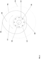
- Fig. 2 shows an enlarged view of the cam (128) of Fig.1 .
- the cam (128) rotates around a centre of rotation (140).
- the cam may comprise a splined bore (139).
- the cam may further comprise 8 (eight) of tapped holes (138) on the same PCD with equal distance apart with the PCD having its centre at the centre of rotation (140).
- a double ended arrow indicates the cam (128) can rotate in both directions (142).
- a apex (199) is the highest point of the cam (128) and an indent (198) the lowest point of the cam (128), a cam face (196) which run all the way around the cam (128), a dotted circle (118) indicating a 360° path of the apex (199) of the cam when rotating, and a dotted circle (137) indicating a 360° path of the indent (198) of the cam when rotating.
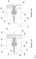
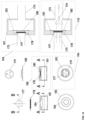
- FIG.3 shows enlarged views of part of the engagement system (115) of Fig.1 .
- schematic 115A shows the engagement valve assembly (115) in the open state.
- the engagement system may comprise a valve piston housing (149), a valve seat housing (148) having a valve seat (147), a coil spring (144) in the uncompressed state, a valve piston (145) having a valve face (146), 2 (two) pressure seals (143, and 143), a circlip (116) and a lever (114).
- the lever is shown having a pivoting point (109) which is firmly fixed in relation to the piston valve housing (149) and, having a hole (150) to provide for fixing a linkage to a brake pedal (not shown).
- the schematic 115B shows the engagement valve assembly (115) in the shut position and hence no oil flowing through it.
- the lever (114) has been actuated by the brake pedal through a linkage connected (not shown) in the hole (150) and is in a different position (compared to engagement system 115A). In this configuration, the lever (114) pushed the valve piston (145), so that the valve face (146) mates with the valve seat (147). Thus sealing off the oil supply through it.
- the coil spring (144) is in the compressed state and assists in opening the valve when desired.
- Fig. 4 shows enlarged views of part of the disengagement system (106) of Fig.1 .
- the schematic 106A shows the disengagement valve assembly (106) in the open state.
- the disengagement valve assembly (106) of Fig. 4 is shown to comprise a valve piston housing (149), a valve seat housing (148) having a valve seat (147), a coil spring (144) in the uncompressed state, a valve piston (145) having a valve face (146), 2 (two) pressure seals (143, and 143), a pin (153) and a lever (114).
- the lever (114) having a pivoting point (109) which is firmly fixed in relation to the piston valve housing (149) and having a hole (150) to provide for fixing a linkage to a brake pedal and or a hand brake lever (not shown).
- An arrow indicates direction of movement (151) of the lever (114) and having an elongated slot at the other end and, its current position as showing the slot located by a pin (153) to the valve piston (145) end protruding from the valve piston housing (149).
- the oil flow passes through the disengagement valve assembly (106) shown by arrows indicating direction of oil flow (154).
- the oil flow is delivered by 2 (two) single acting hydraulic cylinders (120, and 136, not shown) as these contract.
- the oil flow exits the disengagement valve assembly (106) into the sump (101, not shown).
- the schematic 106B shows the disengagement valve assembly (106) in the shut position and hence no oil flowing through it.
- the lever (114) has been actuated by the brake pedal and/or a hand brake lever through a linkage connected (not shown) in the hole (150).
- the hand brake lever is in a different position (compared to disengagement system 106A) such that it has pushed the valve piston (145) so that the valve face (146) mates with the valve seat (147). Thus sealing off the oil supply through it.
- This pressure head ensures a tight seal to any flow of oil in the eventuality of an over pressure occurring in the hydraulic circuit (A) associated with the disengagement valve assembly (106).
- the valve piston (145) shuts off the oil supply from the hydraulic pump (103 not shown) and, the coil spring (144) assists the valve piston to move away from the valve seat (147).
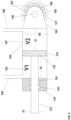
- Fig. 5 shows an enlarged view of part of one hydraulic cylinder assembly (126) of Fig.1 .
- Fig. 5 shows a longitudinal cross-sectional view of a double acting hydraulic cylinder (126) having a volume V1 (163) dimensionalized, a volume V2 (167) dimensionalized, an Inlet/outlet pipe for volume 1 (159), an inlet/outlet pipe for volume V2 (160), a piston rod (123), a cylinder gland (124), 2 (two) pressure seals (143, and 143), a piston rod guide bush (161), a piston (125), a pin (150), a clevis (162), a roller follower (127) comprising of bearing rollers (164), an inner bearing ring (166), and an outer bearing ring (165).
- All double acting hydraulic cylinders (126, 129) used herein may be of identical specifications and dimensions.
- each hydraulic cylinder assembly of each pair of hydraulic cylinder assembly are preferably of identical specifications and dimensions.
- Fig. 6 shows an enlarged view of part of the hydraulic circuit (C) between the hydraulic cylinder assemblies (126, 129) of Fig.1 .
- Fig.6 shows the longitudinal cross-sectional view of 2 (two) double acting hydraulic cylinders (126, 129) cross connected as per the network of pipes (C) without any valves. This is to clarify how a balanced transfer of the oil takes place when the cylinders are reciprocated, assuming that the system has been sealed and pressurised and temperature will remain constant providing for a constant oil volume.
- Fig.7 shows enlarged views of part of the single acting pistons (120, 136) of Fig.1 .
- the single acting piston in schematic A is a longitudinal cross-section of a single acting hydraulic cylinder (120) having a piston (119), a pressure seal (143), an outlet pipe (174), and an inlet pipe (175).
- Single acting piston in schematic B shows the same cylinder in the fully contracted position, an arrow indicating direction of movement (151).
- Single acting piston in schematic C is the longitudinal cross-section of a single acting hydraulic cylinder (136) having a piston (134), a pressure seal (143), an inlet/outlet pipe (176), an arrow indicating direction of movement (151) of the piston to a point of full extension.
- Single acting piston in schematic D shows the same cylinder in the fully contracted position, an arrow indicating direction of movement (151).
- FIG. 8 shows enlarged views of part of the secondary brake valve (105) of Fig.1 .
- the schematic 105A shows the handbrake valve assembly (105) in the open state having a valve piston housing (149), a valve seat housing (148) having a valve seat (147), a coil spring (144) in the uncompressed state, a valve piston (145) having a valve face (146), a pressure seals (143), a circlip (116), a lever (114).
- the lever (114) comprises a pivoting point (109) which is firmly fixed in relation to the piston valve housing (149) and, having a hole (150) to provide for fixing a linkage to a handbrake lever (not shown).
- the linkage configuration further comprises a connection to the engagement valve assembly (115) (not shown) and/or the disengagement valve assembly (106) (not shown).
- the oil flow is delivered by the reciprocation of the 2 (two) double acting hydraulic cylinder (126, and 129, not shown).
- An arrow indicating direction of movement (151) of the valve piston assisted by the coil spring (144) to be in the open position.
- the schematic 105B shows the handbrake valve assembly (105) in the shut position and hence no oil flowing through it.
- the lever (114) has been actuated by a handbrake lever (not shown) through a linkage (not shown) connected in the hole (150) and is in a different position (compared to hand brake system 105A).
- the position of the lever (114) such that it has pushed the valve piston (145) so that the valve face (146) mates with the valve seat (147).
- the coil spring (144) is in the compressed state and assists in opening the valve when desired.
- FIG. 9 shows enlarged views of part of the master brake valve (113) of Fig.1 .
- the schematic 113A shows the master brake valve assembly (113) in the open state having a valve piston housing (149), a valve seat housing (148) having a valve seat (147), a coil spring (144) in the uncompressed state, a valve piston (145) having a valve face (146), a pressure seal (143).
- An arrow indicates direction of movement (151) of the valve piston (145), with oil passing through the master brake valve assembly (113) shown by arrows indicating direction of oil flow (154).
- the oil flow is delivered by the reciprocation of the 2 (two) double acting hydraulic cylinders (126, and 129, not shown).
- the valve piston housing (149) is connected to a master brake cylinder (112; not shown) at the opposite end of the valve piston face (146).
- a group of 3 (three) small arrows indicating direction of oil flow (154) indicate oil returning from the chamber between the valve piston (145).
- the schematic 113B shows the master brake valve assembly (113) in the shut position and hence no oil flowing through it.
- the master brake valve assembly (113) has pushed the valve piston (145), indicated by an arrow indicating direction of movement (151) of the valve piston (145), so that the valve face (146) mates with the valve seat (147).
- the coil spring (144) is in the compressed state and assists in opening the valve when desired.
- a group of 2 (two) small arrows indicating direction of oil flow (154) indicate oil entering from the master brake cylinder (112, not shown) into the chamber.
- the oil enters between the valve piston (145) and the valve piston housing (149) sealed with a pressure seal (143).
- This oil from the master brake cylinder (112; not shown) moves the valve piston towards the valve seat (147) an arrow indicating direction of movement (151).
- the amount of oil entering the said chamber determines the degree of movement of the valve piston (145) towards the valve seat (147).
- the degree of movement creates a restriction to the oil flow between the valve face (146) and the valve seat (147) depending on the distance between them, this restriction is responsible for the amount of braking force delivered to the rotating cam (128; not shown).
- Fig. 10 shows enlarged views of the one way valves of Fig.1 .
- References 104 and 110 are indicated for the valves but the details shown in these views are applicable to all the one way valves of Figure 1 . In particular, these are:
- Fig. 11 shows an enlarged view of a pressure reservoir of Fig.1 (applicable to either 102A or 102C) having a floating piston (186) with a pressure seal (143), a Schrader valve (185), a gas chamber (187) and oil (158) separated from the gas chamber (187) by the floating piston (186) having a pressure seal (143).
- the pressure reservoir technology has been around for many years and is presently deployed in the hydraulic industry and is common practise therefore need not be discussed any further.
- Fig. 12 shows enlarged views of the sensors, signals, stop valves, directional arrows of Fig.1 for the reader's clarity:
- Fig. 13 shows enlarged views of part of one hydraulic cylinder assembly (129, 135) of Fig.1 .
- the schematic 135A shows a longitudinal cross-section of a double acting hydraulic cylinder having a piston rod (133), an Inlet/outlet pipe for volume V2 (160), an Inlet/outlet pipe for volume V1 (159), right-hand part of transmission housing acting as a linear guide (132) as in Fig. 1 .
- Fig.14 shows another example of a braking system. This is generally similar to Fig. 1 but with the following variations.
- the cam (128) is rotating in an anti-clockwise direction.
- the roller followers (127, and 127) attached to the clevises (162, and 162) are attached to the piston rods (123, and 133) ends instead of the ends of the body tubes of the double acting hydraulic cylinder (126, and 129).
- the ends of the body tubes of the double acting hydraulic cylinder (126, and 129) are attached to the pistons (119, and 134) of the single acting hydraulic cylinders (120, and 136) respectively.
- FIG. 15 shows the cam (128) has rotated by 45° (degrees) in a clockwise direction as compared to the cam (128) in Fig. 1 .
- This rotation of the cam (128) subsequently this has caused the 2 (two) double acting hydraulic cylinders (126, and 129) to move towards the right as indicated by 2 (two) arrow indicating direction of movement (151, and 151) thus pumping oil around in the circuit with the network of pipes (C), no other changes have taken place compared to Fig. 1 .
- Fig. 16 shows the cam (128) has rotated by 90° (degrees) in a clockwise direction as compared to the cam (128) in Fig. 1 .
- the rotation of the cam (128) subsequently causes the 2 (two) double acting hydraulic cylinders (126, and 129) to move towards the right as indicated by an arrow indicating direction of movement (151).
- the double acting hydraulic cylinder (126) is fully extended and the double acting hydraulic cylinder (129) is full contracted.
- Fig. 17 shows the cam (128) has rotated by 135° (degrees) in a clockwise direction as compared to the cam (128) in Fig. 1 .
- the rotation of the cam (128) subsequently causes the 2 (two) double acting hydraulic cylinders (126, and 129) to move towards the left as indicated by an arrow indicating direction of movement (151).
- the flow of the pumped oil has changed direction in part of the network of pipes (C) as compared to Fig. 1 .
- the other changes that have occurred are that of the 4 (four) one way valves grouped together on the right-hand side of Fig. 1 and Fig. 17 below the reservoir in the network of pipes (C) have changed status due to the change in the direction of flow of the pumped oil.
- the group of 4 (four) one way valves (104C, 204C, 110C, and 210C) are actuated by the pressure differential caused by the pumping action of the oil by the 2 (two) double acting hydraulic cylinders (126, and 129) in the network of pipes (C).
- the oil velocity is zero when the cam (128) is in position as per Fig. 16 during it its rotation.
- the 2 (two) double acting hydraulic cylinders (126, and 129) will have to change their direction of travel every 180° (degrees) of rotation of the cam (128).
- pumping oil with a velocity providing a sinusoidal wave form This is a preferred form this factor is well understood in the field of mathematics and applied mechanics and need not be discussed any further herein.
- the form may be of a different wave form used in velocity of reciprocating pistons.
- Fig. 18 shows the example of Fig.16 with the secondary brake valve engaged.
- the cam (128) in a static position with the 2 (two) single acting hydraulic cylinders (120, and 136) fully extended.
- the left-hand double acting hydraulic cylinder (126) also fully extended and the right-hand double acting hydraulic cylinder (129) fully contracted.
- the hydraulic cylinders having their roller followers (127, and 127) engaged with the cam face (196), there is no oil flow in the network pipes (C).
- the group of 4 (four) one way valves (104C, 204C, 110C, and 210C) in the network of pipes (C) are in their shut position as there is no oil flow or pressure differential in the circuit.
- the handbrake valve assembly is in the shut position and will not allow oil to travel through it, thus causing the oil in the network of pipes (C) and the 2 (two) double acting hydraulic cylinders (126, and 129) to hydraulically lock and therefore the cam (128) cannot rotate in either direction.
- Fig. 19 shows part of yet another example with a plurality of hydraulic cylinder assemblies interfacing with the cam.
- Fig. 20 shows the hydraulic mechanical braking system of Fig.1 with the disengagement system valve open.
- the braking system of the present invention in a passive state, the cam (128) may be rotating in either direction, a double-headed arrow indicating direction of rotation (117), the pistons (119, 134) are fully contracted (retracted) in the cylinders (120,136 respectively).
- the brake engagement valve assembly (115) is in the shut position, the disengagement valve assembly (106) is in the open position, the handbrake valve assembly (105) is in the open position, the master brake valve (113) is in the open position and the 2 (two) double acting hydraulic cylinders (126, 129) are at their mid-stroke position.
- the open valve assembly (115) causes the oil from the hydraulic pump to be delivered to the 2 (two) single acting hydraulic cylinder (120, and 136) to extend pushing the 2 (two) double acting hydraulic cylinders (126, and 129) toward the cam (128) until the roller followers (127, and 127) to engage with the cam face (196). Any additional depression of the brake foot pedal will cause a braking force on the rotating cam (128) by restricting oil flow in the master brake valve (113).
- FIG. 21 an enlarged view of part of another example is shown, in which the hydraulic cylinder assemblies each comprise a single acting piston rather than a double acting piston as in the previous examples.
- This part of the braking system shows the cam (128) engaged with a transmission shaft, two hydraulic cylinder assemblies, a master brake valve (113), a plurality of one way valves (104C, 204C, 110C, 210C) and a secondary brake valve (105).
- a hydraulic circuit connects the hydraulic cylinder assemblies, the master brake valve (113), the plurality of one way valves (104C, 204C, 110C, 210C) and the secondary brake valve (105).
- the braking system of fig.21 may be used in conjunction with the engagement and disengagement system and hydraulic circuits (A) and (B) generally as in the previous examples but they are omitted from this view for clarity.
- the hydraulic cylinder assemblies in this example comprise a piston (125, 130) and a cylinder (126, 129) arranged to provide a single chamber.
- the hydraulic cylinder assemblies in this example are single acting rather than double acting.
- the cam follower (127) is attached to the piston (125, 130) of each assembly and these will reciprocate together relative to the respective cylinder (126, 129) of each assembly.
- hydraulic fluid flows through the circuit as the cylinder (126, 129) and piston (125, 130) of each assembly reciprocate relative to each other.
- the master brake valve (113) is configured to control the flow of fluid around the hydraulic circuit and actuation of the master brake valve (113) obstructs the flow of the fluid in the hydraulic circuit, such that the relative reciprocation of the cylinder (126, 129) and the piston (125, 130) of each assembly, and reciprocation of each cam follower (127), is inhibited or prevented, whereby the cam followers (127) then inhibit or prevent rotation of the cam (128).
- each cam follower (127) is positioned against the cam (128).
- the hydraulic cylinder assemblies are each in a position of maximum contraction or expansion.
- the hydraulic fluid in the hydraulic fluid circuit is shown flowing in an anti - clockwise direction (154).
- Both the master brake valve (113) and the secondary brake valve (105) are in an open position, thus the hydraulic fluid flow is not obstructed, such that no restrictive force is imposed on the cam (128) by the hydraulic cylinder assemblies.
- piston (125) shown on the left in the figure to move into its cylinder (126) and the piston (130) shown on the right to move out of its cylinder (129). This will reverse the direction of flow of the hydraulic fluid in the circuit.
- the plurality of one way valves (104C, 204C, 110C, 210C) in the hydraulic circuit are configured to ensure the hydraulic fluid always enter the master brake valve (113) in the same direction.
- an engagement and disengagement system generally as described above is connected to the hydraulic cylinder assemblies.
- the cylinder (126, 129) of each assembly functions as the single acting piston of the engagement and disengagement system (115, 106) which is acted upon by fluid in the in the second hydraulic circuit (A).
- hydraulic fluid in the second hydraulic circuit (A) therefore urges the hydraulic cylinder assemblies into contact with the cam (128).
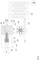
- Fig. 22 illustrates the energy recovery system which may be used with the present invention. This may be used with any of the configurations of the braking system described above and is incorporated within hydraulic circuit (C).
- the energy recovery system allows energy in the hydraulic fluid flowing in the circuit to be harnessed for other purposes. In particular kinetic energy may be used to generate electricity. In addition, heat from the fluid may be extracted.
- Fig. 22 shows the master brake valve assembly (113) in the partially open state.
- the master brake valve assembly has a valve piston housing (149), a valve seat housing (148) having a valve seat (147), a coil spring (144) which is shown here in a partially compressed state, a valve piston (145) having a valve face (146) and a pressure seal (143).
- the position of the valve face (146) and hence its closeness to the valve seat (147) is adjusted by pressure imposed by the master brake cylinder (112 indicated by a circle with the number 112 in it), connected via a pipe to the valve piston housing (149).
- the arrow (117) indicates the direction of rotation of the impeller (191).
- the fluid still with an increased temperature, exits the impeller housing (192) via a pipe connected to a heat exchanger (193).
- Heat can be extracted from the fluid for use in other systems.
- this can be used to power an ammonium hydrogen absorption cooling system (such systems are well known and been around for many years and are still currently deployed in the industry and thus need not be discussed any further) to supplement the air conditioning system on a vehicle or the chiller system on commercial vehicles carrying chilled or frozen foodstuff.
- the fluid exits the heat exchanger (193) and returns to the hydraulic cylinder assemblies as indicated by the lowermost circle with the number 126, and 129 in it.
- the braking system comprises a cam (128), at least two hydraulic cylinder assemblies (126, 129), a hydraulic circuit (C) and a master brake valve (113).
- the cam (128) is coupled to a transmission shaft for rotation therewith.
- Each of the hydraulic cylinders assemblies (126, 129) comprise a piston (125, 130) and a cam follower (127).
- the piston (125, 130) and the hydraulic cylinder (126, 129) reciprocate relative to one another.
- the cam follower (127) is attached to the hydraulic cylinder (126, 129) or the piston (125, 130).
- the hydraulic circuit (C) connects the at least two hydraulic cylinder assemblies and the master brake valve.
- the hydraulic circuit (C) allows fluid to flow between the at least two hydraulic cylinders (126, 129) and the master brake valve (113).
- the master brake valve (113) is configured to control the flow of the fluid around the hydraulic circuit (C).
- the actuation of the master brake valve (113) restricts the flow of the fluid in the hydraulic circuit (C).
- the restriction of fluid in the hydraulic circuit (C) restricts the reciprocation of the hydraulic cylinder (126, 129) and the piston (125, 130).
- the restriction of reciprocation of the hydraulic cylinder (126, 129) and the piston (125, 130) applies a braking force of the cam follower (127) against the cam (128).
- the braking force restricts the rotation of the cam (128) and therefore restricts the rotation of the transmission shaft.
- the braking system also includes an energy recovery system which is configured to transfer energy from the hydraulic fluid flowing in the hydraulic circuit in order to generate electricity and/or to recover heat.
- the cam (128) When the transmission shaft is rotating, the cam (128) will also rotate as long as no flow is being restricted in the hydraulic circuit (C) by the master brake valve (113). From the point of the actuation of the master brake valve (113) up to the point the valve piston (145) interfaces with the valve seat (147), the fluid flow through the valve is increasingly obstructed. The obstruction of the fluid flow in the valve causes fluid flow in the hydraulic circuit (C) to be restricted, and ultimately completely prevented. When the input of the master brake valve (113) is removed, the restriction or prevention of the fluid flow is removed.
- the invention includes an engagement and disengagement system which ensures that the cam followers only engage the cam when braking is required, and are disengaged from the cam when no braking is required.
- the engagement system (115) When braking is required and input is provided to the master brake valve (113) the engagement system (115) will be activated to move the cam follower (127) into engagement with the cam (128). When no braking is required and there is no input to the master brake valve, the disengagement system allows the cam follower (127) to become disengaged from the cam (128).
- the engagement and disengagement system comprises a single acting piston acting on each hydraulic cylinder assembly.
- the single acting piston forces each hydraulic cylinder assembly towards the cam (128) and keeps the cam followers (127) in contact with the cam (128).
- the disengagement system is operated, the single acting piston is released and permits rotation of the cam (128) to push each hydraulic cylinder assembly away to the furthest position so that the cam followers (127) become disengaged from the cam (128).
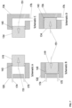
- Figure 23 illustrates a braking system in accordance with the present invention.
- the form of the cam (128) is modified in order to provide an anti-lock braking system (ABS).
- ABS anti-lock braking system
- the other features of the braking system are as described above and the modified cam (128) may be used in any of the previous examples.
- the function of the ABS is to prevent the wheels from locking up during braking, thereby maintaining tractive contact with the road surface and allowing the driver to maintain more control over the vehicle.
- the cam face (196) i.e. the circumferential surface of the cam (128) which contacts the cam followers (127), is formed with two flat faces (142, 143). These are arranged so that both cam followers (127) will contact a respective flat face (142, 143) at the same time.
- each hydraulic cylinder assembly (126, 129) is located along a reciprocating axis which intersects the axis of rotation.
- the two hydraulic cylinder assemblies (126, 129) are located opposite to each other and the cam followers (127) contact the cam (128) at diametrically opposed locations.
- the flat faces (142, 143) are therefore provided at diametrically opposed locations on the cam (128).
- the cam (128) is symmetrical about an axis of symmetry which intercepts the axis of rotation, such that a perigee of the cam and an apogee of the cam are opposite to one another.
- the flat faces (142, 143) are formed at the apogee and perigee.
- the cam (128) can therefore be regarded as a heart-shaped cam as described above but which has been truncated at the top and bottom of the heart shape.
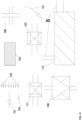
- each cam follower (126, 129) as the cam (128) rotates can be illustrated in the form of a sine wave as shown in Figure 24 .
- a true sine wave will be provided with each peak and trough of the waveform representing a point at which zero braking force is applied to the cam (128).
- the peaks and troughs of the waveform are truncated as shown by the shaded areas in Figure 24 .
- the amplitude of the waveform is truncated by an amount T L , which provides a period of time t x during which no braking force is applied. As the cam (128) is rotating many times per second this leads to multiple periods t x of no braking force per second. This provides the effect of an anti-lock braking system to prevent locking up of the vehicle wheels and skidding of the vehicle.
- the braking system of the present invention is self-contained, requiring no external power source and includes the necessary control elements for a functional braking system suitable for a wide range of vehicles.
- the hydraulic-mechanical braking system of the invention is integrated into the transmission and will therefore also improve steering sensitivity on front wheel drive vehicles.
- the system is not effected by wet weather and since it involves no friction materials (brake pads and brake discs) to retard rotation, it has environmental advantages because no polluting dust is generated.
Landscapes
- Engineering & Computer Science (AREA)
- Mechanical Engineering (AREA)
- Transportation (AREA)
- General Engineering & Computer Science (AREA)
- Chemical & Material Sciences (AREA)
- Combustion & Propulsion (AREA)
- Transmission Of Braking Force In Braking Systems (AREA)
- Regulating Braking Force (AREA)
- Braking Arrangements (AREA)
- Hydraulic Control Valves For Brake Systems (AREA)
Claims (15)
- Bremssystem für ein Fahrzeug, das Folgendes umfasst:einen Nocken (128), der mit einer Antriebswelle oder einem Nachlaufrad zur Drehung mit dieser gekoppelt ist, wobei der Nocken (128) eine umlaufende Nockenfläche (196) umfasst;mindestens zwei Hydraulikzylinderanordnungen (126, 129), wobei jede Anordnung (126, 129) einen Zylinder und einen Kolben (125, 130) umfasst, die so konfiguriert sind, dass sie sich relativ zueinander hin- und herbewegen, und einen Nockenstößel (127), der entweder am Zylinder oder am Kolben (125, 130) angebracht und so ausgelegt ist, dass er die Nockenfläche (196) berührt, wobei die Drehung des Nockens (128) bewirkt, dass sich der Nockenstößel (127) und der Zylinder oder der Kolben (125, 130), an dem er befestigt ist, relativ zum anderen Element, Kolben (125, 130) oder Zylinder, hin- und herbewegen;einen Hydraulikkreis (C), der die Hydraulikzylinderanordnungen (126, 129) miteinander verbindet und durch den Hydraulikfluid fließt, wenn sich der Zylinder und der Kolben (125, 130) jeder Anordnung (126, 129) relativ zueinander hin- und herbewegen;ein Hauptbremsventil (113), das so konfiguriert ist, dass es den Fluidstrom im Hydraulikkreis (C) steuert; undein Betätigungssystem, das eine Benutzereingabevorrichtung umfasst, die dafür konfiguriert ist, das Hauptbremsventil (113) zu betätigen;wobei die Betätigung des Hauptbremsventils (113) den Fluss des Fluids in dem Hydraulikkreis (C) behindert, so dass die relative Hin- und Herbewegung des Zylinders und des Kolbens (125, 130) jeder Anordnung (126, 129) und die Hin- und Herbewegung jedes Nockenstößels (127) gehemmt oder verhindert wird, wodurch die Nockenstößel (127) die Drehung des Nockens (128) hemmen oder verhindern;und dadurch gekennzeichnet, dass die Nockenfläche (196) eine erste und eine zweite flache Fläche (142, 143) umfasst, die so konfiguriert sind, dass bei einer Drehung des Nockens (128) jeder Nockenstößel (127) gleichzeitig mit einer entsprechenden flachen Fläche (142, 143) in Kontakt kommt;wobei sich der Nocken (128) um eine Drehachse dreht und jede Hydraulikzylinderanordnung (126, 129) entlang einersich hin- und herbewegenden Achse angeordnet ist, die die Drehachse des Nockens (128) schneidet, und die erste und zweite flache Fläche (142, 143) an diametral gegenüberliegenden Stellen auf dem Nocken (128) angeordnet sind; undwobei der Nocken (128) symmetrisch zu einer Symmetrieachse ist, die die Drehachse schneidet, so dass ein Perigäum (198) des Nockens und ein Apogäum (199) des Nockens (128) einander gegenüberliegen und die erste und zweite flache Fläche (142, 143) am Apogäum (199) und am Perigäum (198) des Nockens (128) angeordnet sind.
- Bremssystem nach Anspruch 1, wobei jede Hydraulikzylinderanordnung (126, 129) einen doppelt wirkenden Zylinder mit einer ersten Kammer auf einer Seite des Kolbens (125, 130) und einer zweiten Kammer auf der anderen Seite des Kolbens (125, 130) umfasst, wobei der Hydraulikkreis (C) die erste Kammer der ersten Hydraulikzylinderanordnung (126) mit der zweiten Kammer einer zweiten Hydraulikzylinderanordnung (129) und die zweite Kammer der ersten Hydraulikzylinderanordnung (126) mit der ersten Kammer der zweiten Hydraulikzylinderanordnung (129) verbindet.
- Bremssystem nach Anspruch 1 oder 2, wobei jede Hydraulikzylinderanordnung (126, 129) einen einfach wirkenden Zylinder mit einer ersten Kammer umfasst, die zwischen dem Zylinder und dem Kolben (125, 130) definiert ist, wobei der Hydraulikkreis (C) die erste Kammer der ersten Hydraulikzylinderanordnung (126) mit der ersten Kammer der zweiten Hydraulikzylinderanordnung (129) verbindet.
- Bremssystem nach einem der vorhergehenden Ansprüche, wobei der Hydraulikkreis (C) ein Vierwege-Richtungssteuerventilsystem umfasst, das so konfiguriert ist, dass der Durchfluss durch das Hauptbremsventil (113) immer in die gleiche Richtung erfolgt.
- Bremssystem nach einem der vorhergehenden Ansprüche, wobei die Benutzereingabevorrichtung eine Fußbremse umfasst.
- Bremssystem nach einem der vorhergehenden Ansprüche, wobei der Hydraulikkreis (C) ferner ein Sekundärbremsventil (105) umfasst, das ebenfalls dafür konfiguriert ist, den Fluidfluss um den Hydraulikkreis (C) zu steuern, und das Betätigungssystem ferner eine sekundäre Benutzereingabevorrichtung umfasst, die dafür konfiguriert ist, das Sekundärbremsventil (105) zu betätigen.
- Bremssystem nach Anspruch 6, wobei die sekundäre Benutzereingabevorrichtung eine Handbremse ist.
- Bremssystem nach einem der vorhergehenden Ansprüche, wobei jede Hydraulikzylinderanordnung (126, 129) zwischen einer ersten Position, in der der Nockenstößel in Kontakt mit dem Nocken (128) gehalten wird, und einer zweiten Position, in der der Nockenstößel (127) von dem Nocken (128) gelöst ist, beweglich ist, und ferner ein Einrück- und Ausrücksystem (106, 115) umfasst, das dafür konfiguriert ist, jede Hydraulikzylinderanordnung (126, 129) zwischen der ersten Position und der zweiten Position zu bewegen.
- Bremssystem nach Anspruch 8, wobei das Einrück- und Ausrücksystem (106, 115) an das Betätigungssystem gekoppelt ist und so konfiguriert ist, dass es jede Hydraulikzylinderanordnung (126, 129) bei Betätigung des Hauptbremsventils (113) in die erste Position bewegt und jede Hydraulikzylinderanordnung (126, 129) in der ersten Position verriegelt.
- Bremssystem nach Anspruch 9, wobei das Einrück- und Ausrücksystem (106, 115) ferner so konfiguriert ist, dass es jede Hydraulikzylinderanordnung (126, 129) bei Betätigung des Sekundärbremsventils (105) in die erste Position bewegt.
- Bremssystem nach Anspruch 9 oder 10, wobei das Einrück- und Ausrücksystem (106, 115) so konfiguriert ist, dass es jede Hydraulikzylinderanordnung (126, 129) aus der ersten Position löst und eine Bewegung jeder Hydraulikzylinderanordnung (126, 129) in die zweite Position nach dem Lösen des Hauptbremsventils (113) oder des Sekundärbremsventils (105) ermöglicht.
- Bremssystem nach Anspruch 8 bis 11, wobei das Einrück- und Ausrücksystem (106, 115) einen einfach wirkenden Hydraulikzylinder (120, 136), der mit jeder Hydraulikzylinderanordnung (126, 129) gekoppelt ist, und einen weiteren Hydraulikkreis (A) umfasst, der mit jedem einfach wirkenden Hydraulikzylinder (120, 136) verbunden ist, wobei die Zufuhr von Hydraulikfluid zu dem einfach wirkenden Hydraulikzylinder (120, 136) die Hydraulikzylinderanordnung (126, 129) in die erste Position bewegt.
- Bremssystem nach Anspruch 12, wobei das Einrück- und Ausrücksystem (106, 115) ferner mindestens ein Ventil in dem weiteren Hydraulikkreis (A) umfasst, der jedem einfach wirkenden Hydraulikzylinder (120, 136) zugeordnet ist, wobei das mindestens eine Ventil betätigt werden kann, um den Fluss von Hydraulikfluid aus dem einfach wirkenden Hydraulikzylinder (120, 136) zu verhindern, um jede Hydraulikzylinderanordnung (126, 129) in der ersten Position zu verriegeln.
- Bremssystem nach einem der vorhergehenden Ansprüche, das ferner ein Energierückgewinnungssystem umfasst, das so konfiguriert ist, dass es Energie von dem im Hydraulikkreis (C) fließenden Hydraulikfluid überträgt, um Elektrizität zu erzeugen und/oder Wärme von dem im Hydraulikkreis (C) fließenden Hydraulikfluid zurückzugewinnen, und das vorzugsweise femerein drehbares Element (191), das sich in dem Hydraulikkreis (C) befindet und das in Drehung versetzt wird, wenn Fluid durch den Kreis (C) fließt, und eine Stromerzeugungsvorrichtung umfasst, die mit dem drehbaren Element (191) wirkgekoppelt ist, wobei die Stromerzeugungsvorrichtung bevorzugter einen Wechselstromgenerator oder einen Dynamo umfasst.
- Bremssystem nach Anspruch 14, das ferner einen Wärmetauscher (193) umfasst, der sich in dem Hydraulikkreis (C) befindet, durch den das Hydraulikfluid fließt, wobei der Wärmetauscher (193) vorzugsweise an ein Fahrzeug-Klimaanlagensystem oder ein Kühlsystem für eine von einem Fahrzeug zu transportierende Ladung gekoppelt ist.
Priority Applications (1)
| Application Number | Priority Date | Filing Date | Title |
|---|---|---|---|
| MA61916A MA61916B1 (fr) | 2020-10-19 | 2021-10-18 | Systeme de freinage |
Applications Claiming Priority (4)
| Application Number | Priority Date | Filing Date | Title |
|---|---|---|---|
| GB2016583.3A GB2599965B (en) | 2020-10-19 | 2020-10-19 | A braking system |
| GB2016582.5A GB2599964B (en) | 2020-10-19 | 2020-10-19 | A braking system |
| GB2108678.0A GB2599993B (en) | 2020-10-19 | 2021-06-17 | A braking system |
| PCT/EP2021/078811 WO2022084249A1 (en) | 2020-10-19 | 2021-10-18 | A braking system |
Publications (3)
| Publication Number | Publication Date |
|---|---|
| EP4228936A1 EP4228936A1 (de) | 2023-08-23 |
| EP4228936C0 EP4228936C0 (de) | 2025-04-23 |
| EP4228936B1 true EP4228936B1 (de) | 2025-04-23 |
Family
ID=77050447
Family Applications (2)
| Application Number | Title | Priority Date | Filing Date |
|---|---|---|---|
| EP21798314.7A Active EP4228936B1 (de) | 2020-10-19 | 2021-10-18 | Bremssystem |
| EP21798965.6A Active EP4228937B1 (de) | 2020-10-19 | 2021-10-18 | Bremssystem |
Family Applications After (1)
| Application Number | Title | Priority Date | Filing Date |
|---|---|---|---|
| EP21798965.6A Active EP4228937B1 (de) | 2020-10-19 | 2021-10-18 | Bremssystem |
Country Status (9)
| Country | Link |
|---|---|
| US (3) | US20230311821A1 (de) |
| EP (2) | EP4228936B1 (de) |
| CN (1) | CN116648385A (de) |
| CA (2) | CA3196149A1 (de) |
| ES (2) | ES3061636T3 (de) |
| GB (1) | GB2599993B (de) |
| MA (2) | MA61916B1 (de) |
| MX (2) | MX2023004501A (de) |
| WO (2) | WO2022084248A1 (de) |
Families Citing this family (2)
| Publication number | Priority date | Publication date | Assignee | Title |
|---|---|---|---|---|
| GB2599993B (en) * | 2020-10-19 | 2023-06-07 | Baba Golinath Found | A braking system |
| DE102024121586A1 (de) * | 2024-07-30 | 2026-02-05 | Schaeffler Technologies AG & Co. KG | Bremssystem für eine Fahrzeugachse |
Citations (1)
| Publication number | Priority date | Publication date | Assignee | Title |
|---|---|---|---|---|
| US2880825A (en) * | 1955-03-22 | 1959-04-07 | Porter Mack Reid | Hydrodynamic brake |
Family Cites Families (27)
| Publication number | Priority date | Publication date | Assignee | Title |
|---|---|---|---|---|
| US1398875A (en) * | 1920-02-20 | 1921-11-29 | Michael D Maloney | Mechanical brake |
| US2052552A (en) * | 1934-03-28 | 1936-09-01 | Josiah Anstice & Co Inc | Motor car controlling means |
| US2640563A (en) * | 1949-03-04 | 1953-06-02 | Walter F Sanders | Means of withholding braking action when an hydraulic brake is released |
| US4536041A (en) * | 1983-05-10 | 1985-08-20 | Znameni Politekhnichesky Institut | Anti-lock brake system of a motor vehicle |
| US4755007A (en) * | 1987-07-30 | 1988-07-05 | Mollat Edmund C | Anti-skid braking control device including cam and oppositely disposed, reciprocating pistons |
| DE3726318A1 (de) * | 1987-08-07 | 1989-02-16 | Guenter Mieding | Bremsvorrichtung selbsttaetig, reibungslos, hydraulisch exentrisch wirkend |
| DE3936735A1 (de) * | 1989-11-04 | 1991-05-08 | Schaeff Karl Gmbh & Co | Hydrostatischer bremsleistungswandler |
| CN2349079Y (zh) * | 1998-10-09 | 1999-11-17 | 杨迈 | 电子式汽车液压制动防抱死装置 |
| AT501992B1 (de) | 2000-02-21 | 2007-03-15 | Oberaigner Wilhelm | Vorrichtung zur veränderung der drehzahl der angetriebenen räder eines kraftfahrzeuges |
| US6290030B1 (en) * | 2000-03-17 | 2001-09-18 | The University Of Tennessee Research Corporation | Electromagnetic antilock brake system |
| DE10150351A1 (de) * | 2001-10-15 | 2003-05-08 | Bosch Gmbh Robert | Pumpenelement und Kolbenpumpe zur Kraftstoffhochdruckerzeugung |
| US20040089095A1 (en) * | 2002-11-12 | 2004-05-13 | Cheng-Hsun Chiang | Bicycle handlebar with recesses for receiving brake cables |
| US6929103B2 (en) * | 2003-12-15 | 2005-08-16 | Tonand Inc. | Self-energizing brake system |
| US7213691B2 (en) * | 2004-05-11 | 2007-05-08 | Antonio Cannata | Antilock brake system |
| US6942071B1 (en) * | 2004-05-11 | 2005-09-13 | Tonand Inc. | Self-energizing brake system |
| DE102006031855A1 (de) * | 2006-07-10 | 2008-01-17 | Kastriot Merlaku | Brems-Vorrichtung für einspurige Fahrzeuge, vorzugsweise für Fahrräder oder Motorräder |
| US8162621B2 (en) * | 2007-02-12 | 2012-04-24 | Walker Frank H | Hydraulic machine arrangement |
| JP4943220B2 (ja) * | 2007-05-01 | 2012-05-30 | 日立オートモティブシステムズ株式会社 | 液圧制御ユニットおよびブレーキ制御用液圧制御ユニット |
| US8069662B1 (en) * | 2008-10-30 | 2011-12-06 | Robert Bosch Gmbh | Eccentric cam brake booster |
| CN102616218B (zh) * | 2012-03-20 | 2015-08-12 | 魏俊萍 | 一种适于山路的车辆制动装置 |
| CN103010195B (zh) | 2012-12-13 | 2015-10-07 | 田丽欣 | 一种双作用缓速器 |
| CN204978616U (zh) * | 2015-10-10 | 2016-01-20 | 何克鉴 | 汽车智能防撞系统的减速与制动执行机构 |
| CN207842599U (zh) * | 2017-11-30 | 2018-09-11 | 吉利汽车研究院(宁波)有限公司 | 一种汽车空调系统及其同轴换热器 |
| CN109263624B (zh) * | 2018-11-19 | 2020-09-01 | 刘志光 | 汽车力负反馈加力制动方法及装置 |
| DE102019202336A1 (de) * | 2019-02-21 | 2020-08-27 | Robert Bosch Gmbh | Exzenterantrieb einer Exzenterpumpe |
| GB2599965B (en) * | 2020-10-19 | 2023-06-07 | Baba Golinath Found | A braking system |
| GB2599993B (en) * | 2020-10-19 | 2023-06-07 | Baba Golinath Found | A braking system |
-
2021
- 2021-06-17 GB GB2108678.0A patent/GB2599993B/en active Active
- 2021-10-18 CN CN202180085258.4A patent/CN116648385A/zh active Pending
- 2021-10-18 WO PCT/EP2021/078808 patent/WO2022084248A1/en not_active Ceased
- 2021-10-18 ES ES21798965T patent/ES3061636T3/es active Active
- 2021-10-18 ES ES21798314T patent/ES3025477T3/es active Active
- 2021-10-18 MX MX2023004501A patent/MX2023004501A/es unknown
- 2021-10-18 EP EP21798314.7A patent/EP4228936B1/de active Active
- 2021-10-18 MA MA61916A patent/MA61916B1/fr unknown
- 2021-10-18 WO PCT/EP2021/078811 patent/WO2022084249A1/en not_active Ceased
- 2021-10-18 US US18/032,464 patent/US20230311821A1/en active Pending
- 2021-10-18 EP EP21798965.6A patent/EP4228937B1/de active Active
- 2021-10-18 MX MX2023004504A patent/MX2023004504A/es unknown
- 2021-10-18 MA MA61919A patent/MA61919B1/fr unknown
- 2021-10-18 US US18/032,576 patent/US20230382361A1/en active Pending
- 2021-10-18 CA CA3196149A patent/CA3196149A1/en active Pending
- 2021-10-18 CA CA3196150A patent/CA3196150A1/en active Pending
-
2023
- 2023-04-19 US US18/136,428 patent/US12570247B2/en active Active
Patent Citations (1)
| Publication number | Priority date | Publication date | Assignee | Title |
|---|---|---|---|---|
| US2880825A (en) * | 1955-03-22 | 1959-04-07 | Porter Mack Reid | Hydrodynamic brake |
Also Published As
| Publication number | Publication date |
|---|---|
| CA3196149A1 (en) | 2022-04-28 |
| EP4228937C0 (de) | 2025-12-10 |
| EP4228937A1 (de) | 2023-08-23 |
| MX2023004501A (es) | 2023-06-19 |
| GB2599993B (en) | 2023-06-07 |
| US20230311821A1 (en) | 2023-10-05 |
| CN116648385A (zh) | 2023-08-25 |
| US12570247B2 (en) | 2026-03-10 |
| GB202108678D0 (en) | 2021-08-04 |
| US20230382361A1 (en) | 2023-11-30 |
| MA61919B1 (fr) | 2025-12-31 |
| CA3196150A1 (en) | 2022-04-28 |
| WO2022084249A1 (en) | 2022-04-28 |
| EP4228936A1 (de) | 2023-08-23 |
| MX2023004504A (es) | 2023-06-19 |
| GB2599993A (en) | 2022-04-20 |
| WO2022084248A1 (en) | 2022-04-28 |
| EP4228936C0 (de) | 2025-04-23 |
| US20230347852A1 (en) | 2023-11-02 |
| MA61916B1 (fr) | 2025-06-30 |
| EP4228937B1 (de) | 2025-12-10 |
| ES3025477T3 (en) | 2025-06-09 |
| ES3061636T3 (en) | 2026-04-06 |
Similar Documents
| Publication | Publication Date | Title |
|---|---|---|
| US12570247B2 (en) | Braking system | |
| US10138729B2 (en) | Drive assembly with pressure force aggregating piston arrangement for hydraulic motor speed/torque selector | |
| JPH11510239A (ja) | 2本の回転シヤフト間におけるトルク伝動装置 | |
| EP4228938B1 (de) | Bremssystem | |
| US6996982B2 (en) | Method and device for switching hydraulic fluid supplies, such as for a hydraulic pump/motor | |
| US6056090A (en) | Brake actuator | |
| US4082369A (en) | Anti-skid and pressure balanced hydraulic brake system | |
| GB2599964A (en) | Frictionless (non-sacrificial) braking system with kinetic energy recovery | |
| CA1333246C (en) | Hydraulic wheel motor and pump | |
| US3089349A (en) | Locking differential | |
| WO2017007509A2 (en) | Kinetic energy recovery system under braking | |
| US6942071B1 (en) | Self-energizing brake system | |
| RU2656920C1 (ru) | Дифференциал с гидравлическим устройством | |
| US7341318B2 (en) | Circulating fluid regulated braking device for air and land vehicles | |
| CA2545648C (en) | Antilock brake system | |
| JPH0341229A (ja) | 制御型回転差感応継手 |
Legal Events
| Date | Code | Title | Description |
|---|---|---|---|
| STAA | Information on the status of an ep patent application or granted ep patent |
Free format text: STATUS: UNKNOWN |
|
| STAA | Information on the status of an ep patent application or granted ep patent |
Free format text: STATUS: THE INTERNATIONAL PUBLICATION HAS BEEN MADE |
|
| PUAI | Public reference made under article 153(3) epc to a published international application that has entered the european phase |
Free format text: ORIGINAL CODE: 0009012 |
|
| STAA | Information on the status of an ep patent application or granted ep patent |
Free format text: STATUS: REQUEST FOR EXAMINATION WAS MADE |
|
| 17P | Request for examination filed |
Effective date: 20230505 |
|
| AK | Designated contracting states |
Kind code of ref document: A1 Designated state(s): AL AT BE BG CH CY CZ DE DK EE ES FI FR GB GR HR HU IE IS IT LI LT LU LV MC MK MT NL NO PL PT RO RS SE SI SK SM TR |
|
| DAX | Request for extension of the european patent (deleted) | ||
| RAV | Requested validation state of the european patent: fee paid |
Extension state: MA Effective date: 20230505 |
|
| GRAP | Despatch of communication of intention to grant a patent |
Free format text: ORIGINAL CODE: EPIDOSNIGR1 |
|
| STAA | Information on the status of an ep patent application or granted ep patent |
Free format text: STATUS: GRANT OF PATENT IS INTENDED |
|
| INTG | Intention to grant announced |
Effective date: 20241129 |
|
| GRAS | Grant fee paid |
Free format text: ORIGINAL CODE: EPIDOSNIGR3 |
|
| GRAA | (expected) grant |
Free format text: ORIGINAL CODE: 0009210 |
|
| STAA | Information on the status of an ep patent application or granted ep patent |
Free format text: STATUS: THE PATENT HAS BEEN GRANTED |
|
| RAP3 | Party data changed (applicant data changed or rights of an application transferred) |
Owner name: NELMS, CHARAN |
|
| RIN1 | Information on inventor provided before grant (corrected) |
Inventor name: NELMS, CHARAN |
|
| AK | Designated contracting states |
Kind code of ref document: B1 Designated state(s): AL AT BE BG CH CY CZ DE DK EE ES FI FR GB GR HR HU IE IS IT LI LT LU LV MC MK MT NL NO PL PT RO RS SE SI SK SM TR |
|
| REG | Reference to a national code |
Ref country code: GB Ref legal event code: FG4D |
|
| REG | Reference to a national code |
Ref country code: CH Ref legal event code: EP |
|
| REG | Reference to a national code |
Ref country code: DE Ref legal event code: R096 Ref document number: 602021029692 Country of ref document: DE |
|
| REG | Reference to a national code |
Ref country code: IE Ref legal event code: FG4D |
|
| REG | Reference to a national code |
Ref country code: ES Ref legal event code: FG2A Ref document number: 3025477 Country of ref document: ES Kind code of ref document: T3 Effective date: 20250609 |
|
| U01 | Request for unitary effect filed |
Effective date: 20250515 |
|
| U07 | Unitary effect registered |
Designated state(s): AT BE BG DE DK EE FI FR IT LT LU LV MT NL PT RO SE SI Effective date: 20250521 |
|
| REG | Reference to a national code |
Ref country code: MA Ref legal event code: VAGR Ref document number: 61916 Country of ref document: MA Kind code of ref document: B1 |
|
| PG25 | Lapsed in a contracting state [announced via postgrant information from national office to epo] |
Ref country code: GR Free format text: LAPSE BECAUSE OF FAILURE TO SUBMIT A TRANSLATION OF THE DESCRIPTION OR TO PAY THE FEE WITHIN THE PRESCRIBED TIME-LIMIT Effective date: 20250724 Ref country code: NO Free format text: LAPSE BECAUSE OF FAILURE TO SUBMIT A TRANSLATION OF THE DESCRIPTION OR TO PAY THE FEE WITHIN THE PRESCRIBED TIME-LIMIT Effective date: 20250723 |
|
| PG25 | Lapsed in a contracting state [announced via postgrant information from national office to epo] |
Ref country code: PL Free format text: LAPSE BECAUSE OF FAILURE TO SUBMIT A TRANSLATION OF THE DESCRIPTION OR TO PAY THE FEE WITHIN THE PRESCRIBED TIME-LIMIT Effective date: 20250423 |
|
| PG25 | Lapsed in a contracting state [announced via postgrant information from national office to epo] |
Ref country code: HR Free format text: LAPSE BECAUSE OF FAILURE TO SUBMIT A TRANSLATION OF THE DESCRIPTION OR TO PAY THE FEE WITHIN THE PRESCRIBED TIME-LIMIT Effective date: 20250423 |
|
| PG25 | Lapsed in a contracting state [announced via postgrant information from national office to epo] |
Ref country code: RS Free format text: LAPSE BECAUSE OF FAILURE TO SUBMIT A TRANSLATION OF THE DESCRIPTION OR TO PAY THE FEE WITHIN THE PRESCRIBED TIME-LIMIT Effective date: 20250723 |
|
| PG25 | Lapsed in a contracting state [announced via postgrant information from national office to epo] |
Ref country code: IS Free format text: LAPSE BECAUSE OF FAILURE TO SUBMIT A TRANSLATION OF THE DESCRIPTION OR TO PAY THE FEE WITHIN THE PRESCRIBED TIME-LIMIT Effective date: 20250823 |
|
| U20 | Renewal fee for the european patent with unitary effect paid |
Year of fee payment: 5 Effective date: 20251015 |
|
| VSFP | Annual fee paid to validation state [announced via postgrant information from national office to epo] |
Ref country code: MA Payment date: 20251013 Year of fee payment: 5 |
|
| PGFP | Annual fee paid to national office [announced via postgrant information from national office to epo] |
Ref country code: GB Payment date: 20251016 Year of fee payment: 5 |
|
| PG25 | Lapsed in a contracting state [announced via postgrant information from national office to epo] |
Ref country code: SM Free format text: LAPSE BECAUSE OF FAILURE TO SUBMIT A TRANSLATION OF THE DESCRIPTION OR TO PAY THE FEE WITHIN THE PRESCRIBED TIME-LIMIT Effective date: 20250423 |
|
| PGFP | Annual fee paid to national office [announced via postgrant information from national office to epo] |
Ref country code: TR Payment date: 20251010 Year of fee payment: 5 |
|
| PG25 | Lapsed in a contracting state [announced via postgrant information from national office to epo] |
Ref country code: CZ Free format text: LAPSE BECAUSE OF FAILURE TO SUBMIT A TRANSLATION OF THE DESCRIPTION OR TO PAY THE FEE WITHIN THE PRESCRIBED TIME-LIMIT Effective date: 20250423 |
|
| PG25 | Lapsed in a contracting state [announced via postgrant information from national office to epo] |
Ref country code: SK Free format text: LAPSE BECAUSE OF FAILURE TO SUBMIT A TRANSLATION OF THE DESCRIPTION OR TO PAY THE FEE WITHIN THE PRESCRIBED TIME-LIMIT Effective date: 20250423 |
|
| PGFP | Annual fee paid to national office [announced via postgrant information from national office to epo] |
Ref country code: ES Payment date: 20251205 Year of fee payment: 5 |
|
| PLBE | No opposition filed within time limit |
Free format text: ORIGINAL CODE: 0009261 |
|
| STAA | Information on the status of an ep patent application or granted ep patent |
Free format text: STATUS: NO OPPOSITION FILED WITHIN TIME LIMIT |
|
| REG | Reference to a national code |
Ref country code: CH Ref legal event code: L10 Free format text: ST27 STATUS EVENT CODE: U-0-0-L10-L00 (AS PROVIDED BY THE NATIONAL OFFICE) Effective date: 20260304 |
|
| 26N | No opposition filed |
Effective date: 20260126 |