EP4229365B1 - Procédé de fonctionnement d'un capteur vibronique - Google Patents
Procédé de fonctionnement d'un capteur vibronique Download PDFInfo
- Publication number
- EP4229365B1 EP4229365B1 EP21777673.1A EP21777673A EP4229365B1 EP 4229365 B1 EP4229365 B1 EP 4229365B1 EP 21777673 A EP21777673 A EP 21777673A EP 4229365 B1 EP4229365 B1 EP 4229365B1
- Authority
- EP
- European Patent Office
- Prior art keywords
- amplitude
- frequency
- unit
- ref
- predeterminable
- Prior art date
- Legal status (The legal status is an assumption and is not a legal conclusion. Google has not performed a legal analysis and makes no representation as to the accuracy of the status listed.)
- Active
Links
Images

Classifications
-
- G—PHYSICS
- G01—MEASURING; TESTING
- G01F—MEASURING VOLUME, VOLUME FLOW, MASS FLOW OR LIQUID LEVEL; METERING BY VOLUME
- G01F23/00—Indicating or measuring liquid level or level of fluent solid material, e.g. indicating in terms of volume or indicating by means of an alarm
- G01F23/22—Indicating or measuring liquid level or level of fluent solid material, e.g. indicating in terms of volume or indicating by means of an alarm by measuring physical variables, other than linear dimensions, pressure or weight, dependent on the level to be measured, e.g. by difference of heat transfer of steam or water
- G01F23/28—Indicating or measuring liquid level or level of fluent solid material, e.g. indicating in terms of volume or indicating by means of an alarm by measuring physical variables, other than linear dimensions, pressure or weight, dependent on the level to be measured, e.g. by difference of heat transfer of steam or water by measuring the variations of parameters of electromagnetic or acoustic waves applied directly to the liquid or fluent solid material
- G01F23/296—Acoustic waves
- G01F23/2966—Acoustic waves making use of acoustical resonance or standing waves
- G01F23/2967—Acoustic waves making use of acoustical resonance or standing waves for discrete levels
-
- G—PHYSICS
- G01—MEASURING; TESTING
- G01F—MEASURING VOLUME, VOLUME FLOW, MASS FLOW OR LIQUID LEVEL; METERING BY VOLUME
- G01F23/00—Indicating or measuring liquid level or level of fluent solid material, e.g. indicating in terms of volume or indicating by means of an alarm
- G01F23/80—Arrangements for signal processing
-
- G—PHYSICS
- G01—MEASURING; TESTING
- G01F—MEASURING VOLUME, VOLUME FLOW, MASS FLOW OR LIQUID LEVEL; METERING BY VOLUME
- G01F25/00—Testing or calibration of apparatus for measuring volume, volume flow or liquid level or for metering by volume
- G01F25/20—Testing or calibration of apparatus for measuring volume, volume flow or liquid level or for metering by volume of apparatus for measuring liquid level
-
- G—PHYSICS
- G01—MEASURING; TESTING
- G01N—INVESTIGATING OR ANALYSING MATERIALS BY DETERMINING THEIR CHEMICAL OR PHYSICAL PROPERTIES
- G01N11/00—Investigating flow properties of materials, e.g. viscosity, plasticity; Analysing materials by determining flow properties
- G01N11/10—Investigating flow properties of materials, e.g. viscosity, plasticity; Analysing materials by determining flow properties by moving a body within the material
- G01N11/16—Investigating flow properties of materials, e.g. viscosity, plasticity; Analysing materials by determining flow properties by moving a body within the material by measuring damping effect upon oscillatory body
-
- G—PHYSICS
- G01—MEASURING; TESTING
- G01N—INVESTIGATING OR ANALYSING MATERIALS BY DETERMINING THEIR CHEMICAL OR PHYSICAL PROPERTIES
- G01N9/00—Investigating density or specific gravity of materials; Analysing materials by determining density or specific gravity
- G01N9/002—Investigating density or specific gravity of materials; Analysing materials by determining density or specific gravity using variation of the resonant frequency of an element vibrating in contact with the material submitted to analysis
Definitions
- the invention relates to a method for determining and/or monitoring a predeterminable fill level of a medium in a container by means of a vibronic sensor having the features of the preamble of the first claim.
- vibronic sensors can also be used to determine the flow, density, or viscosity of the medium.
- the container is, for example, a tank or a pipeline.
- a generic method results from the DE 10 2005 009 580 A1 .
- Vibronic sensors are widely used in process and/or automation technology.
- they comprise at least one mechanically oscillating unit, such as a tuning fork, a single rod, or a diaphragm.
- this unit is excited to mechanical vibrations by a drive/receiver unit, often in the form of an electromechanical transducer unit, which in turn can be a piezoelectric drive or an electromagnetic drive, for example.
- the applicant manufactures a wide variety of corresponding field devices and, in the case of level measuring devices, markets them, for example, under the names LIQUIPHANT or SOLIPHANT.
- the underlying measuring principles are known from numerous publications.
- the drive/receiver unit excites the mechanically oscillating unit to mechanical vibrations using an electrical excitation signal. Conversely, the drive/receiver unit can receive the mechanical vibrations of the mechanically oscillating unit and convert them into an electrical reception signal.
- the drive/receiver unit is accordingly either a separate drive unit and a separate receiver unit or a combined drive/receiver unit.
- the drive/receiver unit is part of a feedback electrical oscillating circuit, by means of which the excitation of the mechanically oscillating unit to mechanical oscillations takes place.
- the oscillating circuit condition according to which the amplification factor is ⁇ 1 and all phases occurring in the resonant circuit result in a multiple of 360°.
- phase shift can be adjusted, for example, by using a suitable filter, or by means of a control loop to a preset phase shift, the target value.
- DE102006034105A1 it has become known to use an adjustable phase shifter.
- the DE102005015547A1 suggests the use of an all-pass filter.
- the phase shift can also be adjusted using a frequency sweep, as described in the DE102009026685A1 , DE102009028022A1 , and DE102010030982A1
- the phase shift can also be controlled to a preset value using a phase-locked loop (PLL).
- PLL phase-locked loop
- Both the excitation signal and the received signal are characterized by their frequency ⁇ , amplitude A and/or phase ⁇ . Accordingly, changes in these variables are usually used to determine the respective process variable, such as a specified fill level of a medium in a container, or the density and/or viscosity of a medium, or the flow of a medium through a pipe.
- the respective process variable such as a specified fill level of a medium in a container, or the density and/or viscosity of a medium, or the flow of a medium through a pipe.
- a distinction is made as to whether the oscillating unit is covered by the liquid or is freely oscillating.
- These two states, the free state and the covered state are differentiated, for example, by different resonance frequencies, i.e. a frequency shift (see, for example, the DE 33 48 119 C2 ).
- the density and/or viscosity can only be determined with such a measuring device if the oscillating unit is covered by the medium, as described, for example, in the documents DE10050299A1 , DE102007043811A1 , DE10057974A1 , DE102006033819A1 , or DE102015102834A1 .
- the present invention is based on the object of expanding the application range of vibronic sensors.
- a reference value is defined for the amplitude and for the frequency, by means of which the amplitude and the frequency of the received signal are compared.
- One embodiment includes recording the frequency and/or amplitude of the received signal as a function of time. In this way, temporal developments of the sensor can also be observed.
- the method according to the invention thus also advantageously enables the implementation of maintenance, in particular predictive maintenance.
- One embodiment of the method according to the invention includes the conclusion that, in the event of a change in frequency, particularly if the predeterminable frequency limit is exceeded or undershot, and the amplitude remains essentially constant, the oscillating unit is covered by a fluid. If only the frequency changes while the amplitude remains essentially constant, a conclusion can be drawn about the predeterminable fill level being reached.
- the present invention allows the detection of foams and sediments that are usually not detectable or only detectable with considerable effort using conventional evaluation methods.
- the invention concludes that sediment has accumulated in the area of the vibrating unit if the frequency remains essentially constant.
- the vibronic sensor is used to determine a minimum limit level in a container.
- sediment can be detected in the bottom area of the container, which can falsify the statement made about the limit level. With precise knowledge of the presence of sediment in the soil area, a much more accurate determination of the limit level is possible.
- the invention provides that in the event of a change in frequency, where the predeterminable frequency limit is not exceeded or undershot, the presence of sediment in the medium or coverage by foam is inferred.
- the amplitude reference value and/or the frequency reference value are each a value for the amplitude and/or the frequency, which value corresponds to a resonant oscillation of the oscillating unit in the fundamental vibration mode and in air.
- these reference values can be determined during production of the respective sensor and stored, for example, in a memory unit, in a database, or on a data sheet. The reference values then correspond to the delivery state of the sensor. However, they can also be determined by the customer and after installation in the respective container. By determining the reference values individually for each sensor, the usual variances in these values resulting from manufacturing tolerances can be directly counteracted.
- a further embodiment includes the oscillating unit being a tuning fork with a membrane and two vibrating rods attached to the membrane.
- the present invention allows for precise determination and/or monitoring of the preset fill level using a vibronic sensor, which is very easy to implement.
- a vibronic sensor which is very easy to implement.
- Frequency and amplitude allow a more precise determination of the process variable and various negative factors influencing the process variable determination, such as the presence of foam or sediment, can be detected and their influence on the statement made can thus be eliminated.
- Fig. 1 1 shows a vibronic sensor 1. It depicts a sensor unit 3 with an oscillating unit 4 in the form of a tuning fork, which is partially immersed in a medium 2 located in a container 2a.
- the oscillating unit 4 is excited to mechanical vibrations by means of the excitation/receiving unit 5 and can, for example, be a piezoelectric stack or bimorph drive.
- an electronics unit 6 is depicted, by means of which the signal is detected, evaluated, and/or fed.
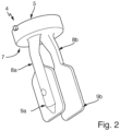
- Fig. 2 1 shows a side view of an oscillating unit 4 in the form of a oscillating fork, such as is integrated in the vibronic sensor 1 marketed by the applicant under the name LIQUIPHANT.
- the oscillating fork 4 comprises two oscillating rods 8a, 8b formed on a membrane 7, to which two paddles 9a, 9b are formed at their ends.
- the oscillating rods 8a, 8b together with the paddles 9a, 9b are often also referred to as fork tines.
- a force is applied by means of a drive/receiver unit 5 which is integrally attached to the side of the membrane 8 facing away from the oscillating rods 7a, 7b.
- the drive/receiver unit 5 is an electromechanical transducer unit and comprises, for example, a piezoelectric element or an electromagnetic drive [not shown].
- the drive unit 5 and the receiver unit are either constructed as two separate units or as a combined drive/receiver unit. If the drive/receiver unit 5 comprises a piezoelectric element 9, the force impressed on the membrane 7 is generated by applying an excitation signal U A , for example in the form of an alternating electrical voltage. A change in the applied electrical voltage causes a change in the geometric shape of the drive/receiver unit 5, i.e.
- the predeterminable fill level of the medium 2 in the container 2a can then be determined based on the received signal U E , for example based on an amplitude A, frequency f, or phase of the received signal U E .
- the method according to the invention now allows for significantly higher accuracy in determining the preset fill level in an expanded range of applications.
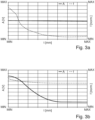
- Various preferred embodiments are described in this context by way of example in Fig. 3 shown.
- reference values f ref , A ref for the amplitude and the frequency are determined, whereby the oscillating unit 4 is excited to resonant oscillations in air.
- the oscillating unit 4 is excited to mechanical oscillations in the fundamental oscillation mode by means of an excitation signal U A and the received signal U E representing the oscillations is received and evaluated with regard to the frequency f and amplitude A.
- the values f, A are compared with the respective reference values f ref , A ref and, for example, a deviation of the measured values f, A from the reference values f ref , A ref is determined, or it is checked whether the frequency f and/or Amplitude A exceeds or falls below the respective preset limit value f ref or A ref .
- Fig. 3 Exemplary diagrams of the frequency f and amplitude A are shown, in which the frequency f and amplitude A are shown for different situations as a function of the immersion depth t of the oscillating unit 4 into the medium 2.
- the frequency f and amplitude A are shown for different situations as a function of the immersion depth t of the oscillating unit 4 into the medium 2.
- an additional consideration of the frequency f may be helpful. If the frequency f remains essentially constant, then, for example, a deposit of sediment may be present in the area of the oscillating unit 4. If, on the other hand, a change in the frequency f is also detected, but which, for example, does not exceed a predeterminable limit value for the frequency, then the presence of sediment in the medium 2 or the covering of the oscillating unit 4 by a foam can be concluded.
Landscapes
- Physics & Mathematics (AREA)
- Fluid Mechanics (AREA)
- General Physics & Mathematics (AREA)
- Acoustics & Sound (AREA)
- Electromagnetism (AREA)
- Thermal Sciences (AREA)
- Engineering & Computer Science (AREA)
- Signal Processing (AREA)
- Measurement Of Levels Of Liquids Or Fluent Solid Materials (AREA)
Claims (3)
- Procédé pour déterminer et/ou surveiller un niveau de remplissage prédéterminable d'un milieu (2) dans un récipient (2a) au moyen d'un capteur vibratoire (1),avec au moins une unité de capteur (3) avec une unité (4) pouvant vibrer mécaniquementcomprenant les étapes de procédé suivantes :- exciter l'unité (4) capable d'osciller mécaniquement en oscillations mécaniques au moyen d'un signal d'excitation (UA) et recevoir les oscillations mécaniques sous la forme d'un signal de réception (UE),- Déterminer une amplitude (A) et une fréquence (f) du signal reçu (UE),- comparaison de la fréquence (f) et de l'amplitude (A) du signal reçu (UE) avec une valeur limite de fréquence (fref) et une valeur limite d'amplitude (Aref) pouvant être prédéfinies, et- détermination d'une atteinte du niveau de remplissage prédéfinissable à l'aide de la comparaison de la fréquence (f) et de l'amplitude (A) du signal de réception (UE) avec la valeur limite de fréquence prédéfinissable (fref) et la valeur limite d'amplitude prédéfinissable (Aref),caractérisé en ceen ce que, dans le cas d'une modification de l'amplitude (A), on conclut à un recouvrement de l'unité vibrante (4) par une mousse ou à la présence d'un sédiment dans le milieu (2) dans la zone de l'unité vibrante (4),en ce que, dans le cas de la variation de l'amplitude (A) et dans le cas d'une fréquence (f) constante, on peut conclure à la présence du sédiment dans le milieu (2) dans la zone de l'unité vibrante (4), eten ce que, dans le cas de la variation de l'amplitude (A) et dans le cas d'une variation de la fréquence (f), la valeur limite de fréquence (fref) pouvant être prescrite n'étant pas dépassée vers le haut ou vers le bas, on conclut à la présence du sédiment dans le milieu (2) dans la zone de l'unité vibrante (4) ou au recouvrement par la mousse.
- Procédé selon la revendication 1,
dans lequel la valeur de référence d'amplitude (Aref) et/ou la valeur de référence de fréquence (fref) sont chacune une valeur pour l'amplitude (A) et/ou la fréquence (f), laquelle valeur correspond à une oscillation de résonance de l'unité vibrante (4) dans le mode fondamental et dans l'air. - Procédé selon la revendication 1 ou 2,
l'unité vibrante (4) étant une fourche vibrante avec une membrane et deux barres vibrantes fixées à la membrane.
Applications Claiming Priority (2)
| Application Number | Priority Date | Filing Date | Title |
|---|---|---|---|
| DE102020127077.1A DE102020127077A1 (de) | 2020-10-14 | 2020-10-14 | Verfahren zum Betreiben eines vibronischen Sensors |
| PCT/EP2021/075124 WO2022078684A1 (fr) | 2020-10-14 | 2021-09-13 | Procédé de fonctionnement d'un capteur vibronique |
Publications (2)
| Publication Number | Publication Date |
|---|---|
| EP4229365A1 EP4229365A1 (fr) | 2023-08-23 |
| EP4229365B1 true EP4229365B1 (fr) | 2025-05-21 |
Family
ID=77914305
Family Applications (1)
| Application Number | Title | Priority Date | Filing Date |
|---|---|---|---|
| EP21777673.1A Active EP4229365B1 (fr) | 2020-10-14 | 2021-09-13 | Procédé de fonctionnement d'un capteur vibronique |
Country Status (5)
| Country | Link |
|---|---|
| US (1) | US12399055B2 (fr) |
| EP (1) | EP4229365B1 (fr) |
| CN (1) | CN116324345B (fr) |
| DE (1) | DE102020127077A1 (fr) |
| WO (1) | WO2022078684A1 (fr) |
Families Citing this family (1)
| Publication number | Priority date | Publication date | Assignee | Title |
|---|---|---|---|---|
| DE102020127077A1 (de) * | 2020-10-14 | 2022-04-14 | Endress+Hauser SE+Co. KG | Verfahren zum Betreiben eines vibronischen Sensors |
Family Cites Families (43)
| Publication number | Priority date | Publication date | Assignee | Title |
|---|---|---|---|---|
| DE3348119C2 (en) | 1983-10-11 | 1989-12-28 | Endress U. Hauser Gmbh U. Co, 7864 Maulburg, De | Device for ascertaining and/or monitoring a predetermined filling level in a container |
| GB2306003B (en) * | 1995-10-02 | 1999-09-29 | Federal Ind Ind Group Inc | Level detector for solids |
| US5895848A (en) * | 1996-01-16 | 1999-04-20 | Flowline Inc. | Apparatus and method for level sensing in a container |
| US5943294A (en) * | 1997-04-08 | 1999-08-24 | Milltronics Ltd. | Level detector for fluent material |
| US5844491A (en) * | 1997-04-30 | 1998-12-01 | Endress + Hauser Gmbh + Co. | Apparatus for establishing and/or monitoring a predetermined filling level in a container |
| DE19720519C2 (de) * | 1997-05-16 | 2000-03-30 | Pepperl & Fuchs | Vorrichtung zur Feststellung und/oder Überwachung eines Füllstandes eines Mediums in einem Behälter |
| US6236322B1 (en) * | 1998-09-09 | 2001-05-22 | Endress + Hauser Gmbh + Co. | Apparatus for establishing and/or monitoring a predetermined filling level in a container |
| DE10014724A1 (de) * | 2000-03-24 | 2001-09-27 | Endress Hauser Gmbh Co | Verfahren und Vorrichtung zur Feststellung und/oder Überwachung des Füllstandes eines Mediums in einem Behälter |
| US6711942B2 (en) * | 2000-10-10 | 2004-03-30 | Endress + Hauser Gmbh & Co. Kg | Apparatus for determining and/or monitoring the viscosity of a medium in a container |
| DE10050299A1 (de) | 2000-10-10 | 2002-04-11 | Endress Hauser Gmbh Co | Vorrichtung zur Bestimmung und/oder Überwachung der Viskosität eines Mediums in einem Behälter |
| DE10057974A1 (de) | 2000-11-22 | 2002-05-23 | Endress Hauser Gmbh Co | Verfahren und Vorrichtung zur Feststellung und/oder Überwachung des Füllstands eines Mediums in einem Behälter bzw. zur Ermittlung der Dichte eines Mediums in einem Behälter |
| DE10242970A1 (de) * | 2002-09-17 | 2004-04-01 | Vega Grieshaber Kg | Vibrations-Füllstandssensor |
| DE10328296A1 (de) | 2003-06-23 | 2005-01-20 | Endress + Hauser Gmbh + Co. Kg | Ansatzalarm bei Feldgeräten |
| US7146845B2 (en) * | 2004-03-24 | 2006-12-12 | Vega Grieshaber Kg | Method for operating tests of vibration level switch sensors and corresponding vibration level switch |
| DE102004036359B4 (de) | 2004-04-19 | 2008-11-06 | Uwt Gmbh | Verfahren zur Ermittlung einer Aussage über die Sicherheit einer mit einer Schwingsonde in einem Behälter durchgeführten Flüssigkeits-Füllstandsmessung |
| DE102004027397A1 (de) * | 2004-06-04 | 2005-12-22 | Endress + Hauser Gmbh + Co. Kg | Vorrichtung zur Bestimmung und/oder Überwachung einer Prozessgröße eines Mediums |
| DE102004055552B4 (de) | 2004-11-17 | 2014-02-13 | Endress + Hauser Gmbh + Co. Kg | Vorrichtung zur Bestimmung und/oder Überwachung eines Füllstandes |
| DE102005009580B4 (de) | 2005-02-28 | 2021-02-04 | Endress+Hauser SE+Co. KG | Verfahren und entsprechende Vorrichtung zur Bestimmung und/oder Überwachung einer Prozessgrösse |
| DE102005015547A1 (de) | 2005-04-04 | 2006-10-05 | Endress + Hauser Gmbh + Co. Kg | Vorrichtung zur Bestimmung und/oder Überwachung einer Prozessgröße eines Mediums |
| DE102005036409A1 (de) | 2005-07-29 | 2007-02-15 | Endress + Hauser Gmbh + Co. Kg | Vorrichtung zur Bestimmung und/oder Überwachung einer Prozessgröße eines Mediums |
| DE102006033819A1 (de) | 2006-07-19 | 2008-01-24 | Endress + Hauser Gmbh + Co. Kg | Vorrichtung zur Bestimmung und/oder Überwachung einer Prozessgröße eines Mediums |
| DE102006034105A1 (de) | 2006-07-20 | 2008-01-24 | Endress + Hauser Gmbh + Co. Kg | Vorrichtung zur Bestimmung und/oder Überwachung einer Prozessgröße eines Mediums |
| DE102007013557A1 (de) | 2006-08-02 | 2008-02-14 | Endress + Hauser Gmbh + Co. Kg | Vorrichtung zur Bestimmung und/oder Überwachung einer Prozessgröße eines Mediums |
| DE102007008669A1 (de) | 2007-02-20 | 2008-08-21 | Endress + Hauser Gmbh + Co. Kg | Verfahren zur Bestimmung und/oder Überwachung einer Prozessgröße eines Mediums und entsprechende Vorrichtung |
| DE102007043811A1 (de) | 2007-09-13 | 2009-03-19 | Endress + Hauser Gmbh + Co. Kg | Verfahren zur Bestimmung und/oder Überwachung der Viskosität und entsprechende Vorrichtung |
| DE102009026685A1 (de) | 2009-06-03 | 2010-12-09 | Endress + Hauser Gmbh + Co. Kg | Verfahren zur Bestimmung oder Überwachung eines vorbestimmten Füllstandes, einer Phasengrenze oder der Dichte eines Mediums |
| DE102009028022A1 (de) | 2009-07-27 | 2011-02-03 | Endress + Hauser Gmbh + Co. Kg | Verfahren zur Bestimmung und/oder Überwachung mindestens einer pysikalischen Prozessgröße eines Mediums |
| SG178196A1 (en) * | 2009-08-14 | 2012-03-29 | Endress & Hauser Gmbh & Co Kg | Multivariable sensor for determining and/ or monitoring fill level and density and/ or viscosity of a liquid in a container |
| DE102010028161B4 (de) | 2010-04-23 | 2023-08-17 | Endress+Hauser SE+Co. KG | Verfahren und Vorrichtung zur Bestimmung und/oder Überwachung eines Grenzfüllstands |
| DE102010030982A1 (de) | 2010-07-06 | 2012-01-12 | Endress + Hauser Gmbh + Co. Kg | Verfahren zur Regelung der Phase in einem Schwingkreis |
| DE102011075113A1 (de) * | 2011-05-03 | 2012-11-08 | Endress + Hauser Gmbh + Co. Kg | Vorrichtung und Verfahren zum Betreiben einer Vorrichtung zur Bestimmung und/oder Überwachung mindestens einer physikalischen Prozessgröße |
| DE102012102589A1 (de) * | 2012-03-26 | 2013-09-26 | Endress + Hauser Gmbh + Co. Kg | Vorrichtung zur Überwachung eines vorbestimmten Füllstands |
| DE102014119061A1 (de) * | 2014-12-18 | 2016-06-23 | Endress + Hauser Gmbh + Co. Kg | Vibronischer Sensor |
| DE102015102834A1 (de) | 2015-02-27 | 2016-09-01 | Endress + Hauser Gmbh + Co. Kg | Vibronischer Sensor |
| US10365194B2 (en) * | 2015-05-01 | 2019-07-30 | Scientific Drilling International, Inc. | High temperature densitometer device and steam quality measurement method and device |
| DE102016111134A1 (de) * | 2016-06-17 | 2017-12-21 | Endress+Hauser Gmbh+Co. Kg | Vibronischer Sensor |
| DE102017102550A1 (de) | 2017-02-09 | 2018-08-09 | Endress+Hauser SE+Co. KG | Zustandsüberwachung eines vibronischen Sensors |
| DE102017111392A1 (de) | 2017-05-24 | 2018-11-29 | Endress+Hauser SE+Co. KG | Vibronischer Sensor mit Störsignal Kompensation |
| DE102017112167A1 (de) | 2017-06-01 | 2018-12-06 | Vega Grieshaber Kg | Vibrations-Grenzstandsensor mit optimiertem induktivem Antrieb |
| DE102017126819A1 (de) | 2017-11-15 | 2019-05-16 | Miele & Cie. Kg | Verfahren zur Steuerung eines Haushaltgeräts mit einem Flüssigkeitsreservoir, Haushaltgerät und Computerprogrammprodukt |
| GB2581352A (en) * | 2019-02-13 | 2020-08-19 | Rosemount Measurement Ltd | Improvements in or relating to vibrating fork level switches |
| DE102019112866A1 (de) * | 2019-05-16 | 2020-11-19 | Endress+Hauser SE+Co. KG | Zustandsüberwachung eines vibronischen Sensors |
| DE102020127077A1 (de) * | 2020-10-14 | 2022-04-14 | Endress+Hauser SE+Co. KG | Verfahren zum Betreiben eines vibronischen Sensors |
-
2020
- 2020-10-14 DE DE102020127077.1A patent/DE102020127077A1/de active Pending
-
2021
- 2021-09-13 EP EP21777673.1A patent/EP4229365B1/fr active Active
- 2021-09-13 CN CN202180070283.5A patent/CN116324345B/zh active Active
- 2021-09-13 US US18/248,539 patent/US12399055B2/en active Active
- 2021-09-13 WO PCT/EP2021/075124 patent/WO2022078684A1/fr not_active Ceased
Also Published As
| Publication number | Publication date |
|---|---|
| US12399055B2 (en) | 2025-08-26 |
| CN116324345A (zh) | 2023-06-23 |
| EP4229365A1 (fr) | 2023-08-23 |
| US20230417591A1 (en) | 2023-12-28 |
| WO2022078684A1 (fr) | 2022-04-21 |
| CN116324345B (zh) | 2026-02-10 |
| DE102020127077A1 (de) | 2022-04-14 |
Similar Documents
| Publication | Publication Date | Title |
|---|---|---|
| EP3485239B1 (fr) | Capteur vibronique | |
| EP3877732B1 (fr) | Multicapteur vibronique | |
| EP3472578B1 (fr) | Capteur vibronique et procédé de fonctionnement d'un capteur vibronique | |
| EP3983761B1 (fr) | Multicapteur vibronique | |
| EP3234518B1 (fr) | Capteur vibronique | |
| EP3555575B1 (fr) | Capteur du type vibronique avec compensation de signaux parasites | |
| WO2018145858A1 (fr) | Surveillance de l'état d'un capteur vibronique | |
| EP3532808B1 (fr) | Procédé permettant de surveiller l'état d'un résonateur électromécanique | |
| WO2016128217A1 (fr) | Dispositif pour déterminer et/ou surveiller au moins une grandeur de processus d'un milieu | |
| EP3969853B1 (fr) | Surveillance de l'état d'un capteur vibronique | |
| EP4168759B1 (fr) | Symetrisation d'un capteur vibronique | |
| EP4229365B1 (fr) | Procédé de fonctionnement d'un capteur vibronique | |
| WO2019120941A1 (fr) | Procédé de surveillance de l'état d'un capteur vibronique | |
| DE102017111392A1 (de) | Vibronischer Sensor mit Störsignal Kompensation | |
| EP4168758B1 (fr) | Capteur vibronique | |
| DE202021103688U1 (de) | Zustandsüberwachung eines vibronischen Sensors | |
| EP4107493B1 (fr) | Capteur vibronique à sensibilité réduite à la formation de bulles de gaz | |
| EP4413335B1 (fr) | Multicapteur vibronique | |
| DE102016124365A1 (de) | Vibronischer Sensor mit Temperaturkompensation | |
| DE102021122534A1 (de) | Vibronischer Multisensor | |
| DE102021126093A1 (de) | Entkopplungseinheit für einen vibronischen Sensor |
Legal Events
| Date | Code | Title | Description |
|---|---|---|---|
| STAA | Information on the status of an ep patent application or granted ep patent |
Free format text: STATUS: UNKNOWN |
|
| STAA | Information on the status of an ep patent application or granted ep patent |
Free format text: STATUS: THE INTERNATIONAL PUBLICATION HAS BEEN MADE |
|
| PUAI | Public reference made under article 153(3) epc to a published international application that has entered the european phase |
Free format text: ORIGINAL CODE: 0009012 |
|
| STAA | Information on the status of an ep patent application or granted ep patent |
Free format text: STATUS: REQUEST FOR EXAMINATION WAS MADE |
|
| 17P | Request for examination filed |
Effective date: 20230403 |
|
| AK | Designated contracting states |
Kind code of ref document: A1 Designated state(s): AL AT BE BG CH CY CZ DE DK EE ES FI FR GB GR HR HU IE IS IT LI LT LU LV MC MK MT NL NO PL PT RO RS SE SI SK SM TR |
|
| DAV | Request for validation of the european patent (deleted) | ||
| DAX | Request for extension of the european patent (deleted) | ||
| REG | Reference to a national code |
Ref country code: DE Ref legal event code: R079 Ref country code: DE Ref legal event code: R079 Ref document number: 502021007560 Country of ref document: DE Free format text: PREVIOUS MAIN CLASS: G01F0023000000 Ipc: G01F0023296000 |
|
| GRAP | Despatch of communication of intention to grant a patent |
Free format text: ORIGINAL CODE: EPIDOSNIGR1 |
|
| STAA | Information on the status of an ep patent application or granted ep patent |
Free format text: STATUS: GRANT OF PATENT IS INTENDED |
|
| INTG | Intention to grant announced |
Effective date: 20250311 |
|
| RIC1 | Information provided on ipc code assigned before grant |
Ipc: G01N 11/16 20060101ALN20250228BHEP Ipc: G01F 25/20 20220101ALN20250228BHEP Ipc: G01N 9/00 20060101ALN20250228BHEP Ipc: G01F 23/80 20220101ALI20250228BHEP Ipc: G01F 23/296 20220101AFI20250228BHEP |
|
| GRAS | Grant fee paid |
Free format text: ORIGINAL CODE: EPIDOSNIGR3 |
|
| GRAA | (expected) grant |
Free format text: ORIGINAL CODE: 0009210 |
|
| STAA | Information on the status of an ep patent application or granted ep patent |
Free format text: STATUS: THE PATENT HAS BEEN GRANTED |
|
| AK | Designated contracting states |
Kind code of ref document: B1 Designated state(s): AL AT BE BG CH CY CZ DE DK EE ES FI FR GB GR HR HU IE IS IT LI LT LU LV MC MK MT NL NO PL PT RO RS SE SI SK SM TR |
|
| REG | Reference to a national code |
Ref country code: GB Ref legal event code: FG4D Free format text: NOT ENGLISH |
|
| REG | Reference to a national code |
Ref country code: CH Ref legal event code: EP |
|
| REG | Reference to a national code |
Ref country code: DE Ref legal event code: R096 Ref document number: 502021007560 Country of ref document: DE |
|
| REG | Reference to a national code |
Ref country code: IE Ref legal event code: FG4D Free format text: LANGUAGE OF EP DOCUMENT: GERMAN |
|
| P01 | Opt-out of the competence of the unified patent court (upc) registered |
Free format text: CASE NUMBER: APP_28531/2025 Effective date: 20250616 |
|
| REG | Reference to a national code |
Ref country code: NL Ref legal event code: MP Effective date: 20250521 |
|
| PG25 | Lapsed in a contracting state [announced via postgrant information from national office to epo] |
Ref country code: ES Free format text: LAPSE BECAUSE OF FAILURE TO SUBMIT A TRANSLATION OF THE DESCRIPTION OR TO PAY THE FEE WITHIN THE PRESCRIBED TIME-LIMIT Effective date: 20250521 Ref country code: PT Free format text: LAPSE BECAUSE OF FAILURE TO SUBMIT A TRANSLATION OF THE DESCRIPTION OR TO PAY THE FEE WITHIN THE PRESCRIBED TIME-LIMIT Effective date: 20250922 Ref country code: FI Free format text: LAPSE BECAUSE OF FAILURE TO SUBMIT A TRANSLATION OF THE DESCRIPTION OR TO PAY THE FEE WITHIN THE PRESCRIBED TIME-LIMIT Effective date: 20250521 |
|
| PGFP | Annual fee paid to national office [announced via postgrant information from national office to epo] |
Ref country code: DE Payment date: 20250919 Year of fee payment: 5 |
|
| REG | Reference to a national code |
Ref country code: LT Ref legal event code: MG9D |
|
| PG25 | Lapsed in a contracting state [announced via postgrant information from national office to epo] |
Ref country code: NO Free format text: LAPSE BECAUSE OF FAILURE TO SUBMIT A TRANSLATION OF THE DESCRIPTION OR TO PAY THE FEE WITHIN THE PRESCRIBED TIME-LIMIT Effective date: 20250821 Ref country code: GR Free format text: LAPSE BECAUSE OF FAILURE TO SUBMIT A TRANSLATION OF THE DESCRIPTION OR TO PAY THE FEE WITHIN THE PRESCRIBED TIME-LIMIT Effective date: 20250822 |
|
| PG25 | Lapsed in a contracting state [announced via postgrant information from national office to epo] |
Ref country code: NL Free format text: LAPSE BECAUSE OF FAILURE TO SUBMIT A TRANSLATION OF THE DESCRIPTION OR TO PAY THE FEE WITHIN THE PRESCRIBED TIME-LIMIT Effective date: 20250521 Ref country code: PL Free format text: LAPSE BECAUSE OF FAILURE TO SUBMIT A TRANSLATION OF THE DESCRIPTION OR TO PAY THE FEE WITHIN THE PRESCRIBED TIME-LIMIT Effective date: 20250521 |
|
| PGFP | Annual fee paid to national office [announced via postgrant information from national office to epo] |
Ref country code: IT Payment date: 20250923 Year of fee payment: 5 |
|
| PG25 | Lapsed in a contracting state [announced via postgrant information from national office to epo] |
Ref country code: BG Free format text: LAPSE BECAUSE OF FAILURE TO SUBMIT A TRANSLATION OF THE DESCRIPTION OR TO PAY THE FEE WITHIN THE PRESCRIBED TIME-LIMIT Effective date: 20250521 |
|
| PG25 | Lapsed in a contracting state [announced via postgrant information from national office to epo] |
Ref country code: HR Free format text: LAPSE BECAUSE OF FAILURE TO SUBMIT A TRANSLATION OF THE DESCRIPTION OR TO PAY THE FEE WITHIN THE PRESCRIBED TIME-LIMIT Effective date: 20250521 |
|
| PGFP | Annual fee paid to national office [announced via postgrant information from national office to epo] |
Ref country code: AT Payment date: 20251020 Year of fee payment: 5 Ref country code: FR Payment date: 20250922 Year of fee payment: 5 |
|
| PG25 | Lapsed in a contracting state [announced via postgrant information from national office to epo] |
Ref country code: RS Free format text: LAPSE BECAUSE OF FAILURE TO SUBMIT A TRANSLATION OF THE DESCRIPTION OR TO PAY THE FEE WITHIN THE PRESCRIBED TIME-LIMIT Effective date: 20250821 |
|
| PG25 | Lapsed in a contracting state [announced via postgrant information from national office to epo] |
Ref country code: IS Free format text: LAPSE BECAUSE OF FAILURE TO SUBMIT A TRANSLATION OF THE DESCRIPTION OR TO PAY THE FEE WITHIN THE PRESCRIBED TIME-LIMIT Effective date: 20250921 |
|
| PG25 | Lapsed in a contracting state [announced via postgrant information from national office to epo] |
Ref country code: LV Free format text: LAPSE BECAUSE OF FAILURE TO SUBMIT A TRANSLATION OF THE DESCRIPTION OR TO PAY THE FEE WITHIN THE PRESCRIBED TIME-LIMIT Effective date: 20250521 |
|
| PG25 | Lapsed in a contracting state [announced via postgrant information from national office to epo] |
Ref country code: DK Free format text: LAPSE BECAUSE OF FAILURE TO SUBMIT A TRANSLATION OF THE DESCRIPTION OR TO PAY THE FEE WITHIN THE PRESCRIBED TIME-LIMIT Effective date: 20250521 Ref country code: SM Free format text: LAPSE BECAUSE OF FAILURE TO SUBMIT A TRANSLATION OF THE DESCRIPTION OR TO PAY THE FEE WITHIN THE PRESCRIBED TIME-LIMIT Effective date: 20250521 |
|
| PG25 | Lapsed in a contracting state [announced via postgrant information from national office to epo] |
Ref country code: CZ Free format text: LAPSE BECAUSE OF FAILURE TO SUBMIT A TRANSLATION OF THE DESCRIPTION OR TO PAY THE FEE WITHIN THE PRESCRIBED TIME-LIMIT Effective date: 20250521 |
|
| PG25 | Lapsed in a contracting state [announced via postgrant information from national office to epo] |
Ref country code: EE Free format text: LAPSE BECAUSE OF FAILURE TO SUBMIT A TRANSLATION OF THE DESCRIPTION OR TO PAY THE FEE WITHIN THE PRESCRIBED TIME-LIMIT Effective date: 20250521 |
|
| PG25 | Lapsed in a contracting state [announced via postgrant information from national office to epo] |
Ref country code: SK Free format text: LAPSE BECAUSE OF FAILURE TO SUBMIT A TRANSLATION OF THE DESCRIPTION OR TO PAY THE FEE WITHIN THE PRESCRIBED TIME-LIMIT Effective date: 20250521 |
|
| REG | Reference to a national code |
Ref country code: DE Ref legal event code: R097 Ref document number: 502021007560 Country of ref document: DE |
|
| PG25 | Lapsed in a contracting state [announced via postgrant information from national office to epo] |
Ref country code: RO Free format text: LAPSE BECAUSE OF FAILURE TO SUBMIT A TRANSLATION OF THE DESCRIPTION OR TO PAY THE FEE WITHIN THE PRESCRIBED TIME-LIMIT Effective date: 20250521 |
|
| PLBE | No opposition filed within time limit |
Free format text: ORIGINAL CODE: 0009261 |
|
| STAA | Information on the status of an ep patent application or granted ep patent |
Free format text: STATUS: NO OPPOSITION FILED WITHIN TIME LIMIT |
|
| REG | Reference to a national code |
Ref country code: CH Ref legal event code: L10 Free format text: ST27 STATUS EVENT CODE: U-0-0-L10-L00 (AS PROVIDED BY THE NATIONAL OFFICE) Effective date: 20260402 |
|
| 26N | No opposition filed |
Effective date: 20260224 |