EP4229367B1 - Vorrichtung zum zählen von gegenständen - Google Patents
Vorrichtung zum zählen von gegenständen Download PDFInfo
- Publication number
- EP4229367B1 EP4229367B1 EP21782722.9A EP21782722A EP4229367B1 EP 4229367 B1 EP4229367 B1 EP 4229367B1 EP 21782722 A EP21782722 A EP 21782722A EP 4229367 B1 EP4229367 B1 EP 4229367B1
- Authority
- EP
- European Patent Office
- Prior art keywords
- counting device
- counting
- window
- wall
- lens
- Prior art date
- Legal status (The legal status is an assumption and is not a legal conclusion. Google has not performed a legal analysis and makes no representation as to the accuracy of the status listed.)
- Active
Links
Images

Classifications
-
- G—PHYSICS
- G01—MEASURING; TESTING
- G01J—MEASUREMENT OF INTENSITY, VELOCITY, SPECTRAL CONTENT, POLARISATION, PHASE OR PULSE CHARACTERISTICS OF INFRARED, VISIBLE OR ULTRAVIOLET LIGHT; COLORIMETRY; RADIATION PYROMETRY
- G01J5/00—Radiation pyrometry, e.g. infrared or optical thermometry
- G01J5/02—Constructional details
- G01J5/08—Optical arrangements
- G01J5/0806—Focusing or collimating elements, e.g. lenses or concave mirrors
-
- G—PHYSICS
- G06—COMPUTING OR CALCULATING; COUNTING
- G06M—COUNTING MECHANISMS; COUNTING OF OBJECTS NOT OTHERWISE PROVIDED FOR
- G06M1/00—Design features of general application
- G06M1/08—Design features of general application for actuating the drive
- G06M1/10—Design features of general application for actuating the drive by electric or magnetic means
- G06M1/101—Design features of general application for actuating the drive by electric or magnetic means by electro-optical means
-
- G—PHYSICS
- G01—MEASURING; TESTING
- G01J—MEASUREMENT OF INTENSITY, VELOCITY, SPECTRAL CONTENT, POLARISATION, PHASE OR PULSE CHARACTERISTICS OF INFRARED, VISIBLE OR ULTRAVIOLET LIGHT; COLORIMETRY; RADIATION PYROMETRY
- G01J1/00—Photometry, e.g. photographic exposure meter
- G01J1/02—Details
- G01J1/0271—Housings; Attachments or accessories for photometers
-
- G—PHYSICS
- G01—MEASURING; TESTING
- G01J—MEASUREMENT OF INTENSITY, VELOCITY, SPECTRAL CONTENT, POLARISATION, PHASE OR PULSE CHARACTERISTICS OF INFRARED, VISIBLE OR ULTRAVIOLET LIGHT; COLORIMETRY; RADIATION PYROMETRY
- G01J1/00—Photometry, e.g. photographic exposure meter
- G01J1/02—Details
- G01J1/04—Optical or mechanical part supplementary adjustable parts
- G01J1/0407—Optical elements not provided otherwise, e.g. manifolds, windows, holograms, gratings
-
- G—PHYSICS
- G01—MEASURING; TESTING
- G01J—MEASUREMENT OF INTENSITY, VELOCITY, SPECTRAL CONTENT, POLARISATION, PHASE OR PULSE CHARACTERISTICS OF INFRARED, VISIBLE OR ULTRAVIOLET LIGHT; COLORIMETRY; RADIATION PYROMETRY
- G01J1/00—Photometry, e.g. photographic exposure meter
- G01J1/02—Details
- G01J1/04—Optical or mechanical part supplementary adjustable parts
- G01J1/0407—Optical elements not provided otherwise, e.g. manifolds, windows, holograms, gratings
- G01J1/0411—Optical elements not provided otherwise, e.g. manifolds, windows, holograms, gratings using focussing or collimating elements, i.e. lenses or mirrors; Aberration correction
-
- G—PHYSICS
- G01—MEASURING; TESTING
- G01J—MEASUREMENT OF INTENSITY, VELOCITY, SPECTRAL CONTENT, POLARISATION, PHASE OR PULSE CHARACTERISTICS OF INFRARED, VISIBLE OR ULTRAVIOLET LIGHT; COLORIMETRY; RADIATION PYROMETRY
- G01J5/00—Radiation pyrometry, e.g. infrared or optical thermometry
- G01J5/02—Constructional details
- G01J5/04—Casings
-
- G—PHYSICS
- G01—MEASURING; TESTING
- G01J—MEASUREMENT OF INTENSITY, VELOCITY, SPECTRAL CONTENT, POLARISATION, PHASE OR PULSE CHARACTERISTICS OF INFRARED, VISIBLE OR ULTRAVIOLET LIGHT; COLORIMETRY; RADIATION PYROMETRY
- G01J5/00—Radiation pyrometry, e.g. infrared or optical thermometry
- G01J5/02—Constructional details
- G01J5/04—Casings
- G01J5/041—Mountings in enclosures or in a particular environment
- G01J5/045—Sealings; Vacuum enclosures; Encapsulated packages; Wafer bonding structures; Getter arrangements
-
- G—PHYSICS
- G01—MEASURING; TESTING
- G01J—MEASUREMENT OF INTENSITY, VELOCITY, SPECTRAL CONTENT, POLARISATION, PHASE OR PULSE CHARACTERISTICS OF INFRARED, VISIBLE OR ULTRAVIOLET LIGHT; COLORIMETRY; RADIATION PYROMETRY
- G01J5/00—Radiation pyrometry, e.g. infrared or optical thermometry
- G01J5/02—Constructional details
- G01J5/04—Casings
- G01J5/048—Protective parts
-
- G—PHYSICS
- G01—MEASURING; TESTING
- G01J—MEASUREMENT OF INTENSITY, VELOCITY, SPECTRAL CONTENT, POLARISATION, PHASE OR PULSE CHARACTERISTICS OF INFRARED, VISIBLE OR ULTRAVIOLET LIGHT; COLORIMETRY; RADIATION PYROMETRY
- G01J5/00—Radiation pyrometry, e.g. infrared or optical thermometry
- G01J5/02—Constructional details
- G01J5/05—Means for preventing contamination of the components of the optical system; Means for preventing obstruction of the radiation path
-
- G—PHYSICS
- G01—MEASURING; TESTING
- G01J—MEASUREMENT OF INTENSITY, VELOCITY, SPECTRAL CONTENT, POLARISATION, PHASE OR PULSE CHARACTERISTICS OF INFRARED, VISIBLE OR ULTRAVIOLET LIGHT; COLORIMETRY; RADIATION PYROMETRY
- G01J5/00—Radiation pyrometry, e.g. infrared or optical thermometry
- G01J5/02—Constructional details
- G01J5/08—Optical arrangements
- G01J5/0875—Windows; Arrangements for fastening thereof
-
- G—PHYSICS
- G06—COMPUTING OR CALCULATING; COUNTING
- G06M—COUNTING MECHANISMS; COUNTING OF OBJECTS NOT OTHERWISE PROVIDED FOR
- G06M11/00—Counting of objects distributed at random, e.g. on a surface
Definitions
- the present invention relates to a counting device in a passageway, preferably installed in an urban environment, for counting objects passing through a detection zone and/or detecting their direction of passage.
- the field of the invention is preferably that of devices for detecting passers-by in a place of passage, preferably in an urban environment.
- An aim of the invention is to remedy at least one of the aforementioned drawbacks.
- the measuring lens of the counting device according to the invention may comprise germanium or polyethylene.
- Polyethylene has good transmission of luminous flux at at least one wavelength between 5 and 12 micrometers but is more fragile than Germanium: the measuring lens can be made of polyethylene (in comparison with the window) because the lens is more protected inside the device according to the invention compared to the window.
- the window of the counting device according to the invention may comprise a protective covering positioned on one side of the window overlooking the exterior of said counting device
- the window of the counting device according to the invention may comprise, along the direction of propagation of said flow on the optical axis between the window and the measuring lens, a thickness greater than 1 millimeter and/or less than 25 millimeters.
- the window of the counting device according to the invention can be a lens.
- the measuring lens, preferably its optical center, of the counting device according to the invention can be positioned at a distance from the surface of the ground greater than 500 millimeters and/or less than 1000 millimeters, preferably between 700 to 850 millimeters .
- the measuring lens of the counting device according to the invention can be held in means for holding the counting means, said holding means comprising at least a first flange which is in contact with said window.
- the measuring lens of the counting device according to the invention may comprise a Fresnel lens.
- the measuring lens of the counting device according to the invention is a Fresnel lens.
- the Fresnel lens can include a field angle greater than 6 degrees.
- the counting device can comprise two windows each comprising germanium, preferably each being entirely composed of germanium, the measuring lens being arranged to be able to be positioned in front of, preferably centered on, one or the other of the two windows according to two reversible positions of the counting means in said device
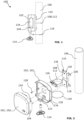
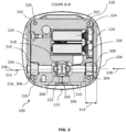
- FIGURES 1, 2 And 3 illustrate a first non-limiting embodiment of a counting device 100 according to the invention.
- the measuring lens 304 and said window 104 are arranged to transmit a flow emitted by the objects present in said detection zone to said counting means 302.
- the counting device 100 is a device 100 which provides the protective wall 102 to protect the counting means 302 from the environment external to said counting device 100.
- the counting means 302 is therefore less subject to vandalism since it is protected by its protective envelope, the wall 102 of the counting device 100.
- the wall also makes it possible to ensure tightness of the counting means 302. For example, the latter is protected by the wall 102 from humidity and/or insects which could lodge or lay eggs in the counting means 302.
- the germanium window 104 has mechanical properties which allow the counting device 100 to guarantee strong resistance to the external environment, such as that encountered in an urban environment such as bad weather, temperature changes, shocks. mechanical (less than or equal to 5 Joules (J) as defined by the electrical protection index IK 08). Consequently, the counting device 100 according to the invention is more robust.
- the window 104 ensures the solidity and mechanical protection of the counting means 302.
- the germanium window 104 ensures additional protection for the measuring lens 304.
- germanium weakly attenuates the signal used for measurement. Consequently, the arrangement of the counting device 100 allows it both to be resistant to its external environment while guaranteeing a sufficient signal level to achieve the performance necessary for counting objects.
- the measuring lens 304 is an optical component, that is to say a refractive element.
- the focal length of the measuring lens 304 is greater than or equal to 18 millimeters (mm) and less than or equal to 30 millimeters.
- the counting device 100 optionally comprises hooking means 108 arranged to fix the wall 102 to a support 106.
- the support 106 illustrated in figure 1 is an urban pole 106 on which the counting device 100 is hung.
- the support 106 can also be a traffic sign, an advertising panel or billboard.
- the support 106 can be the part relating to the post or the board part (ie support) fixed to the post. Consequently, the counting device 100 can be directly positioned on different pre-existing urban elements. The counting device 100 can therefore be positioned easily in the urban environment.
- the fixing support 110 illustrated in figure 2 comprises, in its center, an opening 118 arranged to accommodate a part of the clamping flange 112.
- the part of the clamping flange 112 arranged to be positioned in the opening 118 comprises a clamping means 126.
- the clamping means 126 is arranged to adjust the diameter of the clamping flange 112 so that the latter holds the fixing support 110 against the post 106.
- the mounting bracket 110 illustrated on the figures 1 and 2 comprises a central groove 120, raised, with a thickness of less than 10 centimeters and greater than 1 millimeter, over the entire length of the fixing support 110 so as to leave a small space available between the post 106 and said fixing support 110. This space makes it possible in particular to insert the clamping means 126 of the clamping flange 112 into the opening 118.
- the wall 102 of the counting device 100 illustrated in figures 1, 2 And 3 is formed by an assembly of several parts arranged to be fixed to each other in a removable manner.
- the parts of the wall 102 can be fixed by interlocking and/or with fixing means.
- the wall 102 of the counting device 100 illustrated in figure 2 comprises two parts 102 1 and 102 2 fixed together by interlocking so as to form the interior volume of the wall 102.
- the wall 102 of the counting device 100 is removable, which allows simplified access to the counting means 302. For example, in the event of a malfunction of the counting means 302, an operator can come on site to recover the counting means 302 without dismantling the entire counting device 100.
- a key 114 is illustrated on the figures 1 and 2 .
- the key 114 is removably mounted in a locking latch 122 of the counting device 100.
- the locking latch 122 is arranged to block access to the counting means 302. In particular, the locking latch 122 locks the interlocking of the two parts 102 1 and 102 2 of the wall 102.
- the locking latch 122 is arranged to only be opened by the key 114. Consequently, the wall 102 of the counting device 100 can only be opened and/or dismantled by the key 114.
- This part 102 2 of the wall 102 comprises a first series of holes 134 arranged to receive a first fixing means 128 for fix a part 102 2 of the wall 102 to the fixing support 110.
- the first series of holes 134 comprises, in a non-limiting manner, two holes 134 positioned the part of the wall 102 in contact with the fixing support.
- the anti-theft device 116 links both the counting means 302 to the post 106 and the counting means 302 to the wall 112.
- the measuring lens composition 304 adapts to the environment in which the counting device 100 can be mounted.
- the focal length of the measuring lens 304 is preferably equal to 25 millimeters when the measuring lens 304 comprises germanium.
- the focal length of the measuring lens 304 is preferably equal to 23 millimeters, when the measuring lens 304 comprises polyethylene.
- the measuring lens 304 includes two diopters. A first diopter oriented towards the sensor 306 and a second diopter positioned on one side of the window 104 overlooking the exterior of said counting device 100.
- This protective coating may comprise a carbon material, preferably adamantine carbon also known by the English name Diamond Like Carbon (DLC).
- adamantine carbon also known by the English name Diamond Like Carbon (DLC).
- the counting device 100 comprises a space 314, in the direction of propagation 328 of said flow on the optical axis 312 between the window 104 and the measuring lens 304, of at least 5 millimeters between the optical center of the measuring lens 304 and the window 104 positioned in front of said measuring lens 304.
- the measuring lens 302 in particular its optical center (not shown), is positioned 850 millimeters plus or minus 10 millimeters from the surface of the ground.
- range we mean the visual range corresponding to the maximum distance up to which the sensor 306 of the measuring means 305 can detect objects.
- the visual range of the sensor 306 is estimated along an axis perpendicular to its photosensitive surface of the sensor 306 and extending from this surface until the sensor 306 no longer distinguishes an object.
- the counting means 302 illustrated in Figure 3 includes, but is not limited to, a power supply 324.
- the power supply may be a rechargeable battery or batteries.
- the counting means can be autonomous, for example based on an electromagnetic power supply with the use of inductance.
- the optical axis 312 of the measuring lens 304 is orthogonal, plus or minus 5 degrees, to the direction of movement of said objects circulating in the detection zone. In this way, the detection of the flow by the sensor 306 is more precise.
- the counting device 100 may optionally comprise means of communication (not shown) (wired or non-wired) and arranged to communicate data and/or receive data with a control device (not shown) positioned at the outside of said device 100 and/or inside said device 100.
- the communication means can be arranged to communicate the data of a detected object or several objects detected in the detection zone to an information collecting box, which can communicate with a long-range computer network to transmit the passage data (including for example counting and direction) of one or more objects detected, for example by cellular radio communication using, for example, a modem or a SIM card.
- FIG. 4 illustrates a second example of a counting device 400 according to the invention.
- the counting device 400 illustrated in Figure 4 comprises the same elements as the counting device 100 illustrated on the figures 1, 2 And 3 . Thus, only the differences with the device 100 illustrated on the figures 1, 2 And 3 will be described.
- the counting device 400 illustrated in figure 4 does not include hooking means 108 as illustrated on the figures 1, 2 And 3 .
- the wall 102 of the counting device 400 forms a post connected to a floor carrying said device 400.
- the counting device 100 forms a single unit.
- the wall 102 counting device 400 is composed of two parts fixed in a removable manner.
- a first part corresponding to a hatch 402 and comprising an interior volume in which the counting means 302 is positioned.
- the hatch 402 forms the side edges of the post.
- a second part corresponding to a support cover 404 and forming the upper surface of the post.
- the support cover 404 of the wall 102 is arranged to fit and/or fit into the hatch 402 of the wall 102.
- the counting device 400 illustrated in Figure 4 is rectangular in shape.
- the counting device 400 can be cylindrical, square, circular, conical, patatoid, etc. in shape.
- Such an arrangement makes it possible to limit the presence of housing in which, for example, insects could lodge or snow could stagnate, or people could leave waste such as chewing gum.
- the counting device 400 also includes two germanium windows 104 positioned on side edges opposite the wall 102, in particular the hatch 402.
- the counting device 400 illustrated in Figure 4 and similarly to the counting device 100 illustrated in Figure 3 comprises a single measuring lens 304.
- the measuring means 305 comprises a card support 322 for positioning and maintaining two sensor cards 318 and two sensors 306 sensing flow in two directions 328 and/or two different directions.
- the interior volume of the wall 102, in particular of the hatch, is of the same volume as the counting means 302 or of slightly greater volume (i.e. less than more than 30 percent of the volume of the counting means 302).
- the wall 102 of the counting device 400 can be formed from an assembly of wood and/or plastic.
- the wall 102 of the counting device 400 can be formed from an assembly of recycled plastic and/or plastic. Consequently, the counting device 400 can be, in a non-limiting manner, composed from entirely natural materials and/or from recycled materials and/or materials commonly found commercially. Such a composition of the counting device 400 makes it possible to guarantee robustness, measurement quality, protection of the counting means 302 and to adapt to ecological requirements and/or urban aesthetics.
- the counting means 302 is held in the interior volume of the hatch 402 by the support cover 404.
- the counting means 302 is embedded in the support cover 404 to be maintained in the interior volume of the wall 102 , particularly in the interior volume of cavity 402.
Landscapes
- Physics & Mathematics (AREA)
- General Physics & Mathematics (AREA)
- Spectroscopy & Molecular Physics (AREA)
- Engineering & Computer Science (AREA)
- Theoretical Computer Science (AREA)
- Photometry And Measurement Of Optical Pulse Characteristics (AREA)
- Geophysics And Detection Of Objects (AREA)
- Control Of Conveyors (AREA)
Claims (15)
- Zählvorrichtung (100, 400) umfassend:- eine Wand (102), die ein Innenvolumen begrenzt,- ein Zählmittel (302) für Objekte, das in dem Innenvolumen positioniert ist, wobei das Zählmittel umfasst:o ein Messmittel (305), das so angeordnet ist, dass es einen Lichtstrom bei mindestens einer Wellenlänge zwischen 5 und 12 Mikrometer, der in Richtung des Zählmittels (302) von den in einem Erfassungsbereich befindlichen Objekten emittiert wird, aufzeichnet und/oder erfasst, undo eine Messlinse (304), die den Erfassungsbereich außerhalb der Zählvorrichtung (100, 400) optisch begrenzt, wobei die Linse mit dem Rest des Zählmittels (302) durch eine wasserdichte Verbindung zusammengebaut ist, die das Messmittel (305) vor Staub und/oder Feuchtigkeit von außerhalb des Zählmittels (302) schützt, dadurch gekennzeichnet,dass die Wand (102) der Zählvorrichtung (100, 400) ein Fenster (104) umfasst:- Germanium enthaltend, vorzugsweise vollständig aus Germanium bestehend, und- vor, vorzugsweise zentriert auf der Messlinse (304) positioniert ist, sodass eine Aufnahme zwischen der Linse (304) und dem Fenster (104) gebildet wird,- das durch eine dichte Verbindung mit dem Rest der Wand (102) verbunden ist und so das Zählmittel (302) vor Staub und/oder Feuchtigkeit von außerhalb der Wand (102) schützt,wobei die Messlinse (304) und das Fenster (104) angeordnet sind, um den von den in dem Erfassungsbereich vorhandenen Objekten emittierten Lichtstrom in Richtung des Zählmittels zu übertragen (100, 400).
- Zählvorrichtung (100, 400) nach dem vorhergehenden Anspruch, dadurch gekennzeichnet, dass sie eine glatte und nahtlose Außenfläche zwischen dem Fenster (104) und dessen Umrandung (124) umfasst, die in der Wand (102) ausgebildet ist, so dass das Fenster (104) in Bezug auf eine Außenfläche der Wand (102) nicht in Richtung des Inneren der Vorrichtung (100, 400) gedrückt wird.
- Zählvorrichtung (100, 400) nach einem der vorhergehenden Ansprüche, dadurch gekennzeichnet, dass die Messlinse (304) Germanium oder Polyethylen umfasst.
- Zählvorrichtung (100, 400) nach einem der vorhergehenden Ansprüche, dadurch gekennzeichnet, dass das Fenster (104) eine Schutzbeschichtung umfasst, die auf einer Seite des Fensters (104) positioniert ist, die der Außenseite der Zählvorrichtung (100, 400) zugewandt ist.
- Zählvorrichtung (100, 400) nach dem vorhergehenden Anspruch, dadurch gekennzeichnet, dass die Schutzbeschichtung ein kohlenstoffhaltiges Material, vorzugsweise diamantartigen Kohlenstoff, umfasst.
- Zählvorrichtung (100, 400) nach einem der vorhergehenden Ansprüche, dadurch gekennzeichnet, dass das Fenster (104) entlang der Ausbreitungsrichtung (328) des Lichtstroms auf der optischen Achse (312) zwischen dem Fenster (104) und der Messlinse (304) eine Dicke aufweist, die größer als 1 Millimeter und/oder kleiner als 25 Millimeter ist.
- Zählvorrichtung (100, 400) nach einem der vorhergehenden Ansprüche, dadurch gekennzeichnet, dass die Aufnahme in der Ausbreitungsrichtung (328) des Lichtstroms auf der optischen Achse (312) zwischen dem Fenster (104) und der Messlinse (304) einen Raum von mindestens 5 Millimetern zwischen dem optischen Zentrum der Messlinse (304) und dem Fenster (104), das vor der Messlinse (304) positioniert ist, bildet.
- Zählvorrichtung (100, 400) nach einem der vorhergehenden Ansprüche, dadurch gekennzeichnet, dass sie Aufhängemittel (108) umfasst, die so angeordnet sind, dass sie die Wand (102) an einem Träger (106) befestigen.
- Zählvorrichtung (400) nach einem der Ansprüche 1 bis 7, dadurch gekennzeichnet, dass sie einen Pfosten (400) bildet, der mit einem Boden verbunden ist, der die Zählvorrichtung (100, 400) trägt.
- Zählvorrichtung (100, 400) nach einem der vorhergehenden Ansprüche, dadurch gekennzeichnet, dass die Messlinse (304) in einem Abstand von der Bodenoberfläche von mehr als 500 Millimetern und/oder weniger als 1000 Millimetern, vorzugsweise zwischen 700 und 850 Millimetern, positioniert ist.
- Zählvorrichtung (100, 400) nach einem der vorhergehenden Ansprüche, dadurch gekennzeichnet, dass die Messlinse (304) in einem Haltemittel des Zählmittels (302) gehalten wird, wobei das Haltemittel mindestens einen ersten Flansch (308) umfasst, der das Fenster (104) berührt.
- Zählvorrichtung (100, 400) nach einem der vorhergehenden Ansprüche, dadurch gekennzeichnet, dass die Messlinse (304) eine Fresnel-Linse umfasst.
- Zählvorrichtung (100, 400) nach einem der vorhergehenden Ansprüche, dadurch gekennzeichnet, dass die Messlinse (304) umfasst:- einen Durchmesser von mehr als 5 Millimetern und/oder weniger als 25 Millimetern, vorzugsweise gleich 12,7 Millimeter, und/oder- eine Dicke von mehr als 0,1 Millimetern und/oder weniger als 4 Millimetern, vorzugsweise gleich 1 Millimeter.
- Zählvorrichtung (100, 400) nach einem der vorhergehenden Ansprüche, dadurch gekennzeichnet, dass die Wand (102) der Vorrichtung (100, 400) durch einen Zusammenbau aus mehreren Teilen (1021, 1022) gebildet wird, die so angeordnet sind, dass sie lösbar miteinander befestigt werden können.
- Zählvorrichtung (100, 400) nach einem der vorhergehenden Ansprüche, dadurch gekennzeichnet, dass sie zwei Fenster (104) umfasst, die jeweils Germanium enthalten, vorzugsweise jeweils vollständig aus Germanium bestehen, wobei die Messlinse (304) so angeordnet ist, dass sie gemäß zwei umkehrbaren Positionen des Zählmittels (302) in der Vorrichtung (100, 400) vor dem einen oder dem anderen der beiden Fenster (104) positioniert werden kann, vorzugsweise auf dieses zentriert werden kann.
Applications Claiming Priority (2)
| Application Number | Priority Date | Filing Date | Title |
|---|---|---|---|
| FR2010618A FR3115379B1 (fr) | 2020-10-16 | 2020-10-16 | Dispositif de comptage d’objets |
| PCT/EP2021/076108 WO2022078723A1 (fr) | 2020-10-16 | 2021-09-22 | Dispositif de comptage d'objets |
Publications (3)
| Publication Number | Publication Date |
|---|---|
| EP4229367A1 EP4229367A1 (de) | 2023-08-23 |
| EP4229367C0 EP4229367C0 (de) | 2024-07-03 |
| EP4229367B1 true EP4229367B1 (de) | 2024-07-03 |
Family
ID=74183325
Family Applications (1)
| Application Number | Title | Priority Date | Filing Date |
|---|---|---|---|
| EP21782722.9A Active EP4229367B1 (de) | 2020-10-16 | 2021-09-22 | Vorrichtung zum zählen von gegenständen |
Country Status (7)
| Country | Link |
|---|---|
| US (1) | US12154000B2 (de) |
| EP (1) | EP4229367B1 (de) |
| CN (1) | CN116249879A (de) |
| AU (1) | AU2021359632A1 (de) |
| CA (1) | CA3193794A1 (de) |
| FR (1) | FR3115379B1 (de) |
| WO (1) | WO2022078723A1 (de) |
Family Cites Families (12)
| Publication number | Priority date | Publication date | Assignee | Title |
|---|---|---|---|---|
| US3792275A (en) * | 1972-12-26 | 1974-02-12 | Barnes Eng Co | Infrared intrusion sensor |
| NL8900003A (nl) * | 1989-01-02 | 1990-08-01 | Imec Inter Uni Micro Electr | Inrichting en werkwijze voor het behandelen van een of meer plakken materiaal. |
| FR2721126A1 (fr) * | 1994-06-08 | 1995-12-15 | Brime Sa | Dispositif de détection de présence et de sens de passage de mobiles et de personnes en vue du comptage. |
| CN1258820C (zh) * | 1998-06-30 | 2006-06-07 | 罗伯特·博施有限公司 | 电磁辐射的探测装置 |
| WO2007108513A1 (ja) * | 2006-03-22 | 2007-09-27 | Matsushita Electric Industrial Co., Ltd. | バイオセンサーおよび成分濃度測定装置 |
| FR2899003B1 (fr) | 2006-03-27 | 2008-09-19 | Eco Compteur Sarl | Dispositif de comptage et de determination du sens de passage d'etres vivants |
| DE102006032701B3 (de) * | 2006-07-14 | 2008-01-10 | Sensor Instruments Entwicklungs- Und Vertriebs Gmbh | Gerät zum Detektieren einer Laser-angeregten Lumineszenzstrahlung |
| FR2923009B1 (fr) * | 2007-10-30 | 2011-11-04 | Ulis | Detecteur de rayonnement electromagnetique et notamment detecteur infrarouge. |
| US7615751B2 (en) * | 2007-12-27 | 2009-11-10 | Honeywell International Inc. | Adjustable motion detection sensor with cam |
| US8753008B2 (en) * | 2009-06-26 | 2014-06-17 | Fluke Corporation | Protective enclosure for a thermal imaging device of an industrial monitoring system |
| US20120225475A1 (en) * | 2010-11-16 | 2012-09-06 | 1087 Systems, Inc. | Cytometry system with quantum cascade laser source, acoustic detector, and micro-fluidic cell handling system configured for inspection of individual cells |
| JP2013118547A (ja) * | 2011-12-05 | 2013-06-13 | Tamron Co Ltd | 赤外線カメラ |
-
2020
- 2020-10-16 FR FR2010618A patent/FR3115379B1/fr active Active
-
2021
- 2021-09-22 EP EP21782722.9A patent/EP4229367B1/de active Active
- 2021-09-22 CN CN202180067733.5A patent/CN116249879A/zh active Pending
- 2021-09-22 AU AU2021359632A patent/AU2021359632A1/en active Pending
- 2021-09-22 WO PCT/EP2021/076108 patent/WO2022078723A1/fr not_active Ceased
- 2021-09-22 US US18/248,962 patent/US12154000B2/en active Active
- 2021-09-22 CA CA3193794A patent/CA3193794A1/fr active Pending
Also Published As
| Publication number | Publication date |
|---|---|
| FR3115379B1 (fr) | 2022-10-21 |
| EP4229367C0 (de) | 2024-07-03 |
| EP4229367A1 (de) | 2023-08-23 |
| FR3115379A1 (fr) | 2022-04-22 |
| US20230385595A1 (en) | 2023-11-30 |
| CA3193794A1 (fr) | 2022-04-21 |
| CN116249879A (zh) | 2023-06-09 |
| US12154000B2 (en) | 2024-11-26 |
| AU2021359632A1 (en) | 2023-05-11 |
| WO2022078723A1 (fr) | 2022-04-21 |
Similar Documents
| Publication | Publication Date | Title |
|---|---|---|
| EP3682199B1 (de) | System zur messung der bestandteile von sonnenstrahlung | |
| WO2021089802A1 (fr) | Système d'étanchéité connecté pour bâtiments et équipements | |
| WO2020064762A1 (fr) | Dispositif de protection d'un capteur/émetteur optique d'un système d'assistance à la conduite pour véhicule automobile | |
| WO2022078723A1 (fr) | Dispositif de comptage d'objets | |
| WO2023057635A1 (fr) | Dispositif d'imagerie infrarouge | |
| CA3125842A1 (fr) | Accessoire de vision de couche sous plafond pour detecteur infrarouge | |
| WO2004079648A2 (fr) | Dispositif de detection optique pour compteur | |
| EP3821085B1 (de) | Vorrichtung zum zugriff auf eine unterirdische oder oberirdische hoch- und tiefbaustruktur mit einem mehrprotokollkommunikationsmodul und system zur verwaltung einer zugangsvorrichtung | |
| EP2133684A1 (de) | Messzelle für Gerät zur Detektion von Gas in einer Atmosphäre | |
| FR2672124A1 (fr) | Procede et dispositif de controle de l'etat de surface d'un element optique de transmission lumineuse. | |
| FR2789787A1 (fr) | Dispositif de protection perimetrique laser pour piscine | |
| EP3821408B1 (de) | Vorrichtung für zugriff auf eine unterirdische oder oberflächliche bauinfrastruktur mit einer eindringungsdetektionsvorrichtung | |
| FR3069944A1 (fr) | Dispositif de detection d'ouverture | |
| EP1105712A1 (de) | Messvorrichtung der grösse sich bewegender teilchen, insbesondere für regenmessungen | |
| EP3009999A1 (de) | Eingebauter linearer rauchdetektor | |
| EP1557805A1 (de) | Strahlungsdetektor mit Linsen und Spiegeln | |
| FR2789788A1 (fr) | Dispositif de protection perimetrique laser pour piscine | |
| WO2020144232A1 (fr) | Detecteur infrarouge de couche sous plafond | |
| EP0264659A1 (de) | Beobachtungsfenster durch eine Wand, insbesondere einer radioaktiven Zelle | |
| FR2899003A1 (fr) | Dispositif de comptage et de determination du sens de passage d'etres vivants | |
| FR3010191A1 (fr) | Dispositif de detection de la contamination alpha d'objets | |
| FR2942048A1 (fr) | Dispositif de capture d'images 360° comprenant un systeme catadiotrique couple a un capteur d'images. | |
| FR2885420A1 (fr) | Instrument meteorologique utilisant le son produit par les precipitations pour les quantifier | |
| EP3688235A1 (de) | Hochfrequenzsignal-transmissive schachtabdeckung | |
| FR2978544A1 (fr) | Dispositif de controle de la repartition de radiations solaires concentrees sur une zone receveuse |
Legal Events
| Date | Code | Title | Description |
|---|---|---|---|
| STAA | Information on the status of an ep patent application or granted ep patent |
Free format text: STATUS: UNKNOWN |
|
| STAA | Information on the status of an ep patent application or granted ep patent |
Free format text: STATUS: THE INTERNATIONAL PUBLICATION HAS BEEN MADE |
|
| PUAI | Public reference made under article 153(3) epc to a published international application that has entered the european phase |
Free format text: ORIGINAL CODE: 0009012 |
|
| STAA | Information on the status of an ep patent application or granted ep patent |
Free format text: STATUS: REQUEST FOR EXAMINATION WAS MADE |
|
| 17P | Request for examination filed |
Effective date: 20230503 |
|
| AK | Designated contracting states |
Kind code of ref document: A1 Designated state(s): AL AT BE BG CH CY CZ DE DK EE ES FI FR GB GR HR HU IE IS IT LI LT LU LV MC MK MT NL NO PL PT RO RS SE SI SK SM TR |
|
| DAV | Request for validation of the european patent (deleted) | ||
| DAX | Request for extension of the european patent (deleted) | ||
| REG | Reference to a national code |
Ref country code: DE Ref legal event code: R079 Free format text: PREVIOUS MAIN CLASS: G01J0001020000 Ipc: G01J0005080600 Ref document number: 602021015263 Country of ref document: DE |
|
| GRAP | Despatch of communication of intention to grant a patent |
Free format text: ORIGINAL CODE: EPIDOSNIGR1 |
|
| STAA | Information on the status of an ep patent application or granted ep patent |
Free format text: STATUS: GRANT OF PATENT IS INTENDED |
|
| RIC1 | Information provided on ipc code assigned before grant |
Ipc: G01J 5/04 20060101ALI20240201BHEP Ipc: G01J 1/04 20060101ALI20240201BHEP Ipc: G01J 1/02 20060101ALI20240201BHEP Ipc: G01J 5/05 20220101ALI20240201BHEP Ipc: G01J 5/0875 20220101ALI20240201BHEP Ipc: G01J 5/0806 20220101AFI20240201BHEP |
|
| INTG | Intention to grant announced |
Effective date: 20240215 |
|
| GRAS | Grant fee paid |
Free format text: ORIGINAL CODE: EPIDOSNIGR3 |
|
| GRAA | (expected) grant |
Free format text: ORIGINAL CODE: 0009210 |
|
| STAA | Information on the status of an ep patent application or granted ep patent |
Free format text: STATUS: THE PATENT HAS BEEN GRANTED |
|
| AK | Designated contracting states |
Kind code of ref document: B1 Designated state(s): AL AT BE BG CH CY CZ DE DK EE ES FI FR GB GR HR HU IE IS IT LI LT LU LV MC MK MT NL NO PL PT RO RS SE SI SK SM TR |
|
| REG | Reference to a national code |
Ref country code: CH Ref legal event code: EP |
|
| REG | Reference to a national code |
Ref country code: DE Ref legal event code: R096 Ref document number: 602021015263 Country of ref document: DE |
|
| U01 | Request for unitary effect filed |
Effective date: 20240712 |
|
| U07 | Unitary effect registered |
Designated state(s): AT BE BG DE DK EE FI FR IT LT LU LV MT NL PT SE SI Effective date: 20240718 |
|
| U20 | Renewal fee for the european patent with unitary effect paid |
Year of fee payment: 4 Effective date: 20240910 |
|
| PG25 | Lapsed in a contracting state [announced via postgrant information from national office to epo] |
Ref country code: NO Free format text: LAPSE BECAUSE OF FAILURE TO SUBMIT A TRANSLATION OF THE DESCRIPTION OR TO PAY THE FEE WITHIN THE PRESCRIBED TIME-LIMIT Effective date: 20241003 |
|
| PG25 | Lapsed in a contracting state [announced via postgrant information from national office to epo] |
Ref country code: PL Free format text: LAPSE BECAUSE OF FAILURE TO SUBMIT A TRANSLATION OF THE DESCRIPTION OR TO PAY THE FEE WITHIN THE PRESCRIBED TIME-LIMIT Effective date: 20240703 Ref country code: GR Free format text: LAPSE BECAUSE OF FAILURE TO SUBMIT A TRANSLATION OF THE DESCRIPTION OR TO PAY THE FEE WITHIN THE PRESCRIBED TIME-LIMIT Effective date: 20241004 |
|
| PG25 | Lapsed in a contracting state [announced via postgrant information from national office to epo] |
Ref country code: IS Free format text: LAPSE BECAUSE OF FAILURE TO SUBMIT A TRANSLATION OF THE DESCRIPTION OR TO PAY THE FEE WITHIN THE PRESCRIBED TIME-LIMIT Effective date: 20241103 |
|
| PG25 | Lapsed in a contracting state [announced via postgrant information from national office to epo] |
Ref country code: HR Free format text: LAPSE BECAUSE OF FAILURE TO SUBMIT A TRANSLATION OF THE DESCRIPTION OR TO PAY THE FEE WITHIN THE PRESCRIBED TIME-LIMIT Effective date: 20240703 Ref country code: CZ Free format text: LAPSE BECAUSE OF FAILURE TO SUBMIT A TRANSLATION OF THE DESCRIPTION OR TO PAY THE FEE WITHIN THE PRESCRIBED TIME-LIMIT Effective date: 20240703 |
|
| PG25 | Lapsed in a contracting state [announced via postgrant information from national office to epo] |
Ref country code: RS Free format text: LAPSE BECAUSE OF FAILURE TO SUBMIT A TRANSLATION OF THE DESCRIPTION OR TO PAY THE FEE WITHIN THE PRESCRIBED TIME-LIMIT Effective date: 20241003 Ref country code: ES Free format text: LAPSE BECAUSE OF FAILURE TO SUBMIT A TRANSLATION OF THE DESCRIPTION OR TO PAY THE FEE WITHIN THE PRESCRIBED TIME-LIMIT Effective date: 20240703 |
|
| PG25 | Lapsed in a contracting state [announced via postgrant information from national office to epo] |
Ref country code: RS Free format text: LAPSE BECAUSE OF FAILURE TO SUBMIT A TRANSLATION OF THE DESCRIPTION OR TO PAY THE FEE WITHIN THE PRESCRIBED TIME-LIMIT Effective date: 20241003 Ref country code: PL Free format text: LAPSE BECAUSE OF FAILURE TO SUBMIT A TRANSLATION OF THE DESCRIPTION OR TO PAY THE FEE WITHIN THE PRESCRIBED TIME-LIMIT Effective date: 20240703 Ref country code: NO Free format text: LAPSE BECAUSE OF FAILURE TO SUBMIT A TRANSLATION OF THE DESCRIPTION OR TO PAY THE FEE WITHIN THE PRESCRIBED TIME-LIMIT Effective date: 20241003 Ref country code: IS Free format text: LAPSE BECAUSE OF FAILURE TO SUBMIT A TRANSLATION OF THE DESCRIPTION OR TO PAY THE FEE WITHIN THE PRESCRIBED TIME-LIMIT Effective date: 20241103 Ref country code: HR Free format text: LAPSE BECAUSE OF FAILURE TO SUBMIT A TRANSLATION OF THE DESCRIPTION OR TO PAY THE FEE WITHIN THE PRESCRIBED TIME-LIMIT Effective date: 20240703 Ref country code: GR Free format text: LAPSE BECAUSE OF FAILURE TO SUBMIT A TRANSLATION OF THE DESCRIPTION OR TO PAY THE FEE WITHIN THE PRESCRIBED TIME-LIMIT Effective date: 20241004 Ref country code: ES Free format text: LAPSE BECAUSE OF FAILURE TO SUBMIT A TRANSLATION OF THE DESCRIPTION OR TO PAY THE FEE WITHIN THE PRESCRIBED TIME-LIMIT Effective date: 20240703 Ref country code: CZ Free format text: LAPSE BECAUSE OF FAILURE TO SUBMIT A TRANSLATION OF THE DESCRIPTION OR TO PAY THE FEE WITHIN THE PRESCRIBED TIME-LIMIT Effective date: 20240703 |
|
| PG25 | Lapsed in a contracting state [announced via postgrant information from national office to epo] |
Ref country code: SM Free format text: LAPSE BECAUSE OF FAILURE TO SUBMIT A TRANSLATION OF THE DESCRIPTION OR TO PAY THE FEE WITHIN THE PRESCRIBED TIME-LIMIT Effective date: 20240703 |
|
| PG25 | Lapsed in a contracting state [announced via postgrant information from national office to epo] |
Ref country code: MC Free format text: LAPSE BECAUSE OF FAILURE TO SUBMIT A TRANSLATION OF THE DESCRIPTION OR TO PAY THE FEE WITHIN THE PRESCRIBED TIME-LIMIT Effective date: 20240703 |
|
| PG25 | Lapsed in a contracting state [announced via postgrant information from national office to epo] |
Ref country code: SK Free format text: LAPSE BECAUSE OF FAILURE TO SUBMIT A TRANSLATION OF THE DESCRIPTION OR TO PAY THE FEE WITHIN THE PRESCRIBED TIME-LIMIT Effective date: 20240703 |
|
| REG | Reference to a national code |
Ref country code: CH Ref legal event code: PL |
|
| PLBE | No opposition filed within time limit |
Free format text: ORIGINAL CODE: 0009261 |
|
| STAA | Information on the status of an ep patent application or granted ep patent |
Free format text: STATUS: NO OPPOSITION FILED WITHIN TIME LIMIT |
|
| 26N | No opposition filed |
Effective date: 20250404 |
|
| PG25 | Lapsed in a contracting state [announced via postgrant information from national office to epo] |
Ref country code: CH Free format text: LAPSE BECAUSE OF NON-PAYMENT OF DUE FEES Effective date: 20240930 |
|
| PG25 | Lapsed in a contracting state [announced via postgrant information from national office to epo] |
Ref country code: IE Free format text: LAPSE BECAUSE OF NON-PAYMENT OF DUE FEES Effective date: 20240922 |
|
| U20 | Renewal fee for the european patent with unitary effect paid |
Year of fee payment: 5 Effective date: 20250909 |
|
| PG25 | Lapsed in a contracting state [announced via postgrant information from national office to epo] |
Ref country code: RO Free format text: LAPSE BECAUSE OF FAILURE TO SUBMIT A TRANSLATION OF THE DESCRIPTION OR TO PAY THE FEE WITHIN THE PRESCRIBED TIME-LIMIT Effective date: 20240703 |
|
| PG25 | Lapsed in a contracting state [announced via postgrant information from national office to epo] |
Ref country code: CY Free format text: LAPSE BECAUSE OF FAILURE TO SUBMIT A TRANSLATION OF THE DESCRIPTION OR TO PAY THE FEE WITHIN THE PRESCRIBED TIME-LIMIT; INVALID AB INITIO Effective date: 20210922 |
|
| PG25 | Lapsed in a contracting state [announced via postgrant information from national office to epo] |
Ref country code: HU Free format text: LAPSE BECAUSE OF FAILURE TO SUBMIT A TRANSLATION OF THE DESCRIPTION OR TO PAY THE FEE WITHIN THE PRESCRIBED TIME-LIMIT; INVALID AB INITIO Effective date: 20210922 |