EP4230019A1 - Epandeur pneumatique d'engrais - Google Patents
Epandeur pneumatique d'engrais Download PDFInfo
- Publication number
- EP4230019A1 EP4230019A1 EP23156786.8A EP23156786A EP4230019A1 EP 4230019 A1 EP4230019 A1 EP 4230019A1 EP 23156786 A EP23156786 A EP 23156786A EP 4230019 A1 EP4230019 A1 EP 4230019A1
- Authority
- EP
- European Patent Office
- Prior art keywords
- spreading
- distribution
- fertilizer spreader
- grit
- pneumatic fertilizer
- Prior art date
- Legal status (The legal status is an assumption and is not a legal conclusion. Google has not performed a legal analysis and makes no representation as to the accuracy of the status listed.)
- Granted
Links
Images


Classifications
-
- A—HUMAN NECESSITIES
- A01—AGRICULTURE; FORESTRY; ANIMAL HUSBANDRY; HUNTING; TRAPPING; FISHING
- A01C—PLANTING; SOWING; FERTILISING
- A01C15/00—Fertiliser distributors
- A01C15/04—Fertiliser distributors using blowers
-
- A—HUMAN NECESSITIES
- A01—AGRICULTURE; FORESTRY; ANIMAL HUSBANDRY; HUNTING; TRAPPING; FISHING
- A01C—PLANTING; SOWING; FERTILISING
- A01C21/00—Methods of fertilising, sowing or planting
- A01C21/005—Following a specific plan, e.g. pattern
Definitions
- the invention relates to a pneumatic fertilizer spreader for distributing granular spreading material.
- Pneumatic fertilizer spreaders are known from the prior art. Fertilizer spreaders are used for the distribution of granular (granular) spreading material (fertilizer, seed and/or the like.). In order to spread the granular spreading material, fertilizer spreaders of this type have a distribution linkage with a large working width with distribution devices or dispensing elements (e.g. baffle plates) arranged thereon.
- the distribution linkage comprises two lateral booms, each of which has a plurality of distribution lines and dispensing elements for dispensing the material.
- the spreading material is conveyed along the distribution lines, which are arranged at least in sections on the distribution linkage, by means of an air volume flow in the direction of the dispensing elements.
- the spreading elements each have a baffle plate for spreading the grit to form a scattering fan of grit.
- Such a pneumatic fertilizer spreader is for example in DE 10 2018 131 073 A1 described.
- Pneumatic fertilizer spreaders offer the advantage over so-called disc spreaders or centrifugal spreaders, in which the spreading material is distributed by means of a disc-shaped centrifugal mechanism, that site-specific applications (e.g. section control applications) are easier to implement and a better spreading pattern in strong winds (Throw image) can be generated.
- site-specific applications e.g. section control applications
- grit When applying grit to an agricultural area, it can be advantageous, depending on the application process, if the grit is released into the immediate vicinity of the respective plants on the agricultural area. Since a large number of agricultural crops are sown along seed rows, rows of plants form on the agricultural land during the growth phase of the crops. For a particularly effective application of grit, the possibility of a row-related application of grit would therefore be desirable, so that the grit is applied essentially along application strips.
- the application strips can be placed along rows of plants or, e.g. B. for weed control, also run between rows of plants.
- a row-related application along application strips can also be referred to as a band application in contrast to the full-surface application of grit.
- the dispensing elements arranged on the distribution linkage which are each supplied with spreading material via a separate distribution line (conveying line), are typically arranged at a distance of 1.5 meters - in Seen longitudinal direction of the distribution linkage.
- a separate distribution line conveying line
- the large number of delivery lines running along the distribution rods require a lot of space and are correspondingly heavy.
- a band application in row cultures which usually have one of the usual row spacings of 25 cm, 50 cm or 75 cm, is not possible.
- a pneumatic fertilizer spreader which, in a manner known per se, has a distribution linkage for spreading granular spreading material (material), such as fertilizer, seed and/or the like.
- the fertilizer spreader can thus be used not only for spreading fertilizer on an agricultural area, but also for other granular material.
- the distribution linkage comprises two lateral booms, each of which has a plurality of distribution lines, preferably hose lines, and distribution devices for discharging the grit (material).
- the grit can be conveyed along the distribution lines, which are arranged at least in sections on the distribution linkage, by means of an air volume flow in the direction of the distribution devices.
- the distribution linkage extends (in the working position) transversely to a direction of travel of the fertilizer spreader.
- the distribution devices each have at least one spreading element for forming a spreading fan of spreading material.
- the dispensing element can be used as an impact element, e.g. B. be executed as a baffle plate.
- the dispensing element can also be designed as a guide element, which preferably has a curved course, so that the material to be spread pneumatically conveyed onto the guide element is discharged through the curved course, forming a spreading fan.
- the pneumatic fertilizer spreader is characterized in that the distribution devices are each designed to produce a variable number of spreading fans. With a distribution device, it is not only possible to produce exactly one scatter fan from grit, but also an adjustable number of scatter fans created simultaneously by a distribution device. This offers the advantage that the scattering pattern of the material to be distributed can be adjusted more flexibly, in particular it can be better adapted to a row-related application. It is thus possible that plant rows are treated in a targeted manner, e.g. B. be fertilized, or alternatively specifically treated intermediate areas of plant rows, z. B. are fertilized.
- a targeted manner e.g. B. be fertilized, or alternatively specifically treated intermediate areas of plant rows, z. B. are fertilized.
- the optionally variable number of scattering compartments can be less than or equal to 5.
- the distribution devices can each be designed for the selective generation of one spread fan and/or two spread fans.
- the distribution devices can each be designed for the selective generation of one spread fan, two spread fans and/or three spread fans.
- this variable number of spreading fans enables a sufficiently flexible adaptation of the spreading pattern for the most common plant row patterns and, on the other hand, it can be implemented advantageously with regard to the required installation space and costs.
- the term "optional" means that the number of spreading fans that are generated by a specific distribution device during the spreading process can be selected, e.g. B. can be adjusted.
- the selection or adjustment of the number of spreading compartments can be carried out by an appropriate configuration, e.g. B. a manual configuration and / or automated control of the distribution devices, which will be explained below.
- Scatter fans are understood to mean a fan-shaped scatter pattern that can result when grit bounces off a baffle plate or a guide element and then spreads out like a fan on the way to the agricultural area.
- the spread fan is a three-dimensional spread fan.
- the three-dimensional expansion of the spreading fan is made up of the two-dimensional expansion of the spreading fan and the amount of fertilizer contained in the spreading fan.
- Scattering direction can be understood as meaning the mean scattering direction of the scattering material of a scattering fan lying in the scattering fan.
- Adjacent spreading fans are understood to mean spreading fans which are arranged next to one another/following one another in the direction of the longitudinal extent of the distribution linkage.
- the impact area is the impact area of the spreading material on the agricultural area to be treated.
- the distribution devices are each designed to selectively supply adjacent spreading fans with different spreading directions and/or with different impact areas, more preferably with overlap-free impact areas, of the material to be spread generate. This is particularly advantageous for the band application of the grit, since this grit can be applied through the distribution devices in each case on adjacent rows of plants, in particular with pneumatic fertilizer spreaders whose distribution devices are conventionally spaced, z. B. at a distance of about 1.5 meters.
- the distribution devices each have a configurable and/or controllable dividing device which is designed to generate a variable number of grit partial flows from the grit flow arriving at the respective distribution device. In this way, the variable number of spreading compartments on a distribution device can be realized in a particularly advantageous manner.
- the distribution devices each have different application areas, preferably different impact surfaces, for generating different spreading fans, it being possible to change by means of the distribution device to which of the application areas the material arriving on the input side of the respective distribution device is conveyed.
- a compact implementation is advantageously made possible in order to generate the variable number of spread fans.
- the dividing device can have its own feed path, preferably its own feed pipe, for each of the dispensing areas.
- a switch, flaps and/or an opening/closing mechanism can be arranged on the input side of the feed section(s), with which it is possible to adjust and/or change which of the feed section(s) the grit arriving at the respective distribution device on the input side is conveyed to. Accordingly, a flexible control and/or division of the spreading material can be realized in this way to generate the different spreading fans.
- the different dispensing areas of a distribution device are formed by different dispensing elements, preferably by different baffle plates or guide elements, which produce adjacent spreading fans with different spreading directions and are preferably attached to the distribution linkage with different orientations.
- Each of the distribution devices can thus have several baffle plates or guide elements z. B. differently aligned (oriented) and / or arranged differently aligned on the distribution linkage.
- the different dispensing areas of a distribution device are each formed by a single dispensing element, which has impingement surfaces arranged at an angle to one another to form the different dispensing areas having.
- the different dispensing areas of a distribution device are each formed by a single multi-part baffle plate, with the individual sections of the baffle plate being designed to be adjustable relative to one another in order to form the different dispensing areas.
- the different application areas can be manually adjustable relative to one another or can have a controllable actuator system and be automatically adjustable relative to one another by means of the actuator system.
- the dispensing element can have at least one guide web for separating the different dispensing areas and for guiding the grit within an impact area. In this way, a reliable distribution and guidance of the spreading material can be realized in a structurally cost-efficient manner by means of only one dispensing element for generating different spreading fans.
- the pneumatic fertilizer spreader comprises a control device which is set up to change the spreading pattern, preferably to carry out a band application, to control the dividing device in order to change the number of spreading material partial flows.
- the control device can comprise an operator terminal or have a signal connection with an operator terminal.
- the control device is set up to generate a control signal as a function of information about row spacings entered or stored via the operator terminal, preferably for carrying out a belt application and/or for controlling the dividing device.
- One advantage of this is that the function of the control device can be adjusted accordingly by means of a user input.
- the control device can be in signal connection with a detection device.
- the detection device is designed to detect a row of plants or a grid of rows of plants formed by rows of plants and/or to detect a position of the distribution devices relative to a row of plants or a grid of rows of plants.
- the control device can be set up to generate its control signals as a function of the data recorded by the detection device, preferably for carrying out a belt application and/or for controlling the dividing device.
- rows of plants or a grid of rows of plants can be automatically recorded and the control of the distribution process can be automatically adjusted according to the recording.
- the detection device can comprise one or more cameras, e.g. B. are arranged on the distribution linkage and their perspective is directed to the agricultural area to be treated.
- the distribution devices can be configurable and/or controllable for changing the impact areas of the spread fans, preferably for changing the width and/or position of the impact areas.
- the distribution devices are thus each designed to generate a variable number of spread fans and, in addition, the impact areas of the spread fans themselves can be changed.
- a particularly flexible adaptation of the distribution pattern of the individual distribution devices can be achieved, in particular in order to be able to adapt the distribution pattern to a desired belt application if necessary.
- control device is set up to generate control signals for changing the width and/or position of the impact areas as a function of information on row spacing entered or stored via the operator terminal and as a function of the data recorded by the detection device.
- Targeted adjustment based on the row spacing of a stand of plants to be treated can advantageously be made possible.
- At least some of the dispensing elements can each be pivotably arranged on the distribution linkage by means of a pivoting device in order to change the position of the impact area of the spread fan of the dispensing element.
- at least some of the dispensing elements can each have a baffle plate or a guide element, the shape of which can be changed by means of an actuator, in order to change the width of the impact area of the spreading fan of the dispensing element.
- the pneumatic fertilizer spreader comprises at least one dosing device for dosing the grit into the distribution lines, wherein the dosing of the grit can be adjusted, preferably automatically, depending on the variable number of spread compartments.
- the efficiency of the amount of distribution material used can be improved as a result.
- the at least one dosing device can be arranged in the area of the storage container for grit or in the area of the distribution linkage.
- the distribution devices can each be supplied with grit via separate metering devices, and each of the distribution devices can be in fluid communication with the metering device assigned to it via its own distribution line.
- a quantity of grit that is assigned to a distribution device by its Dosing device can be supplied, be manually and / or automatically adjustable, preferably be manually and / or automatically adjustable depending on a number and / or width of the spreading compartments of the distribution device.
- each supply line can be supplied with the respective material to be distributed, for example with a separate dosing device.
- the quantity of distribution material dosed by means of the dosing device can be adjusted manually and/or automatically, for example.
- a quantity of goods to be distributed can be adjusted in a particularly efficient manner with regard to tape application processes.
- the distribution devices can be manually configurable to change the number of spread compartments, e.g. B. manually adjustable and / or manually convertible by a user.
- the number of dispensing elements e.g. B. the number of baffle plates, which are each mounted on the distribution devices
- the number of baffle plates is manually adjusted by a user in accordance with the number of spreading compartments per distribution device.
- predetermined assembly points can be provided for the baffle plates per distribution device.
- the number of installed baffle plates can then be changed as part of the manual configuration.
- the dividing device can be reconfigured accordingly.
- the user can convert the dispensing element according to the number of spreading compartments to be generated, for example by adapting the respective dispensing areas (adapting the different impact surfaces).
- the dividing device can be reconfigured accordingly, e.g. B. by adjusting the open-close mechanism associated with each deployment area accordingly.
- a distribution device can be understood to mean a subassembly which is arranged at the end of a supply line and is fluidically connected and which is designed to spread the grit arriving at the distribution device on the inlet side onto an agricultural area to be treated by means of at least one baffle plate and/or guide element.
- the distribution devices can only be connected to only one of the distribution lines, which are arranged at least in sections on the distribution linkage, for the supply of spreading material.
- adjacent distribution devices are a distance of at least 1 meter, preferably 1.5 meters.
- the initial areas of the different spread fans the can be generated by the same distribution device, viewed in the longitudinal direction (L) of the distribution linkage, have a spacing of ⁇ _ 50 cm.
- the distribution devices each have a length dimension and/or structural size—seen in the direction of longitudinal extension (L) of the distribution rod—which is ⁇ 50 cm.
- the distribution linkage can be mounted in a height-adjustable manner on a carrier vehicle for adjusting its height relative to an agricultural area to be processed, in particular a crop, for example by means of a height-adjustable lifting frame which, for. B. is adjustable in height by a parallelogram linkage.
- the distribution linkage can have a carrier and a central part, the two lateral booms being pivotably attached to the central part.
- the distribution linkage can have a large working width, which is significantly larger than a width of a carrier vehicle of the fertilizer spreader on which the distribution linkage is mounted.
- the working width can e.g. B. be a multiple of the width of the carrier vehicle.
- the working width of the distributor linkage i. H. the width in working position or when fully unfolded, can be at least 15 meters, preferably at least 20 meters.
- the outriggers can be designed to fold in and out, so that they can be folded and folded in for transport.
- Figure 1A shows a schematic perspective view and Figure 1b a rear view of a pneumatic fertilizer spreader according to an embodiment of the invention.
- Figure 1A shows a schematic perspective view of a pneumatic fertilizer spreader 1 for spreading granular agricultural grit according to an embodiment of the invention.
- the direction of travel is marked with the arrow V.
- fertilizer spreader 1 is in particular a fertilizer spreader, by means of which grainy or granular agricultural materials to be spread or distributed, such as fertilizer or microgranules, but also seeds, can be applied.
- the fertilizer spreader 1 is designed as a towed fertilizer spreader, ie designed as an agricultural fertilizer spreader 1 that can be coupled or towed by means of a towing vehicle. At the front end of the fertilizer spreader this has a connecting device such.
- the fertilizer spreader 1 could also be a self-propelled fertilizer spreader 1 and/or a fertilizer spreader 1 that can be attached or is attached to a towing vehicle.
- the carrier vehicle comprises a frame construction, a chassis comprising four running wheels, and a storage container 21 for carrying along and/or providing the grit.
- the storage container 21 can have one or more chambers depending on the number of different spreading materials.
- the fertilizer spreader has a distribution linkage 2 mounted directly or indirectly on a carrier vehicle 9 for spreading granular spreading material.
- the distribution linkage 2 comprises two lateral booms 3 which are pivotally attached at their inner end to a central part 3a and have an outer free end.
- the distribution linkage 2 can, for example, have working widths of more than 20 meters.
- the distribution linkage 2 or the booms 3 can be formed at least in sections by a framework-like linkage structure or by a framework construction.
- the rod structure or the framework construction has a greater height than depth.
- the spreading material is conveyed in the spreading operation along the distribution lines 4, which are arranged at least in sections on the distribution linkage 2, by means of an air volume flow in the direction of the distribution devices 10.
- a dosing device 8 is arranged on the central part 3a, which is designed to dose the spreading material from the storage container 21 via the dosing device 8 in the desired quantity into the individual distribution lines 4.
- the reservoir 21, the dosing device 8 and the grit conveying system between the reservoir and the dosing device 8 can be designed in a manner known per se and is therefore not described in detail here. By way of example only, these components can be designed as described in the disclosure DE 10 2018 131 070 A1 is described.
- the distribution devices 10 each have at least one discharge element, preferably a baffle plate or a guide element, for forming a spreading fan of granular grit, which is described in more detail below.
- the In the present example, distribution devices are spaced 1.5 meters apart from one another, seen in the direction of longitudinal extension L of the distribution linkage.
- the direction of longitudinal extent or the linkage axis of the distribution linkage 2 is marked here with the arrow L.
- the distribution devices 10 of the fertilizer spreader 1 have the special feature that they are each designed to produce a variable number of spread fans, which is described with reference to the following figures.
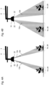
- Figure 2A shows a partial schematic view of a boom in a first tape application scattering mode according to an embodiment of the invention.
- a belt application or a belt application gritting operation is understood here as a row-related application of grit along application strips, in contrast to the full-surface application of grit.
- the AusbringstMail can along rows of plants R or z. B. for weed control, also run between rows of plants, i.e. along intermediate areas Z.
- Figure 2A illustrates a band application where the spreading strips run along rows of plants R.
- the distribution devices 10 of the fertilizer spreader 1 can be configured for the implementation of this first belt application spreading operation in such a way that each distribution device 10 spreads two adjacent spreading fans 12, here the spreading fans 12a and 12b, with different spreading directions 13a, 13b and different non-overlapping impact areas 14 of the spreading material can generate.
- Spreading material is applied to adjacent rows of plants R by means of the spreading fans 12a and 12b, leaving out the intermediate area Z of the rows of plants.
- the individual distribution devices are, for example, 1.5 meters apart along the linkage, this still makes it possible to apply a band to plant row structures whose row spacing is smaller than the spacing of the distribution devices 10 from one another.
- FIG 2A is also shown that the distribution devices 10 are each connected to only one of the distribution lines 4 for supplying grit. How the grit flow conveyed via the associated distribution line 4 and arriving at a distribution device 10 is divided up to produce the multiple grit compartments 12a, 12b is explained below with reference to FIG Figures 6 to 9 explained as an example.
- Figure 2B shows a partial schematic view of a boom in a second tape application spreading mode according to an embodiment of the invention.
- the distribution devices 10 of the fertilizer spreader 1 again produce two adjacent spreading fans 12a and 12b with different ones for carrying out this second band application spreading operation in the spreading operation Spreading directions 13a, 13b and different non-overlapping impact areas 14 of the spreading material, with the spreading material now being applied to adjacent intermediate areas Z of plant rows by means of the spreading fans 12a, 12b, leaving out the plant rows R.
- This can be done, for example, by the same configuration of the distribution devices 10 as in the first belt application -Scattering operation can be achieved, but in contrast to this, the distribution linkage is positioned offset transversely to the rows of plants R by half a row spacing.
- the jet directions 13a, 13b of the scattering fans can also be changed by changing a pivoting position of the baffle plates used to generate the scattering fans.
- the baffle plates can be pivotably arranged on the distribution linkage.
- a particular advantage of the fertilizer spreader 1 is, however, that the distribution devices 10 are each designed to produce a variable number of spread compartments 12a, 12b, 12c, ie the number of simultaneously generated spread compartments that is produced by each distribution device 10 in spreading operation can be adjusted .
- This is exemplified by the Figure 3A 11 showing a partial schematic view of a boom in a third tape application scattering mode.
- the distribution devices 3 can also be configured in such a way that they each produce three different spreading fans 12a, 12b, 12c with different spreading directions and different non-overlapping impact areas 14 of the spreading material during spreading operation.
- This is e.g. B. advantageous for a band application for row spacing of the rows of plants R, which are smaller than the row spacing as in the Figures 2A and 2B shown.
- the scatter fans produced are directed towards the rows of plants R, leaving out the intermediate areas.
- the Figure 3B a fourth belt application scattering operation, which differs from the third belt application scattering operation only in that the spread fan generated is directed towards the intermediate areas Z, leaving out the rows of plants R (similar to the second belt application scattering operation of Figure 2B ).
- the distribution devices 10 can be used to generate the spread fan in the Figures 2A to 3B for example according to the embodiment of FIG figure 7 be carried out, which will be described below. By means of this embodiment, for example, one, two or three spreading compartments can be generated per distribution device 10.
- Figure 4A first shows a schematic partial view of a boom in the first band application spreading operation, as already shown in Figure 2A described.
- Figure 4B shows Figure 4B a fifth tape application spread operation, which differs from that in Figure 4A differs in that the spreading fan 12a, 12b and thus the spreading width 24 generated are widened.
- the scattered fans are directed towards the rows of plants R.
- FIGS 5A and 5B show to the Figures 4A and 4B corresponding litter farms with the difference that the litter fans are now directed towards the intermediate areas Z between the rows of plants. Another difference is that the initial areas 22 of the different spread fans 12a, 12b in the Figures 5A and 5B overlap because they are generated by different impact surfaces of the same baffle plate, while the scatter fans 12a, 12b in the Figures 4A and 4B are generated by different impact plates (cf. figure 6 ).
- FIG 6 shows a highly schematic representation of a distribution device 10 according to an embodiment of the invention.
- the distribution devices 10 have two baffle plates 11a, 11b which are arranged adjacent to one another and which each form different dispensing areas for generating different spreading fans.
- the baffle plates 11a, 11b are attached to the distribution linkage 2 with different orientations.
- deployment areas are here the deployment areas 16a and 16b for generating the scattered fans 12a, 12b (the latter are not shown).
- the discharge areas 16a and 16b are formed by the impact surfaces of the impact plates.
- the distribution devices 10 also each have a configurable and/or controllable dividing device 15 .
- the dividing device 15 is designed to generate a variable number of grit partial flows 18, here the partial flows 18a and 18b, from the grit flow 17 arriving at the respective distribution device via the associated distribution line 4.
- the dividing device 15 can be used to change which of the dispensing areas 16a, 16b the grit arriving at on the input side of the respective distribution device 10 is conveyed to.
- the dividing device 15 has its own feed section 19a, 19b, preferably its own feed pipe, for each of the discharge areas.
- a switch, flap and/or an opening/closing mechanism 20 is arranged on the inlet side of the feed sections 19a, 19b, with which it is possible to adjust and/or change which of the feed section(s) 19a, 19b the grit arriving at the respective distribution device 10 on the inlet side is conveyed to becomes.
- actuatable (pivotable) flaps 20 are shown, which can be brought into an open position in which the grit arriving at the flap can reach the subsequent feed section 19a or 19b and which can be brought into a closed position in which the grit arriving at the flap cannot get into the subsequent feed section 19a or 19b.
- a flap 20 is arranged on the input side of each of the feed sections 19a, 19b. The flaps 20 can be actuated independently of one another.
- no spread fan both flaps in the closed position
- one spread fan only one flap open
- two spread fans both flaps open
- both flaps of each distribution device 10 are open, the flow of grit arriving on the input side of the respective distribution device 10 is divided into two partial flows 18a, 18b of grit, which are each conveyed by means of the air volume flow along one of the feed sections 19a, 19b onto the baffle plates 11a, 11b and there under Formation of the two spread fans 12a, 12b bounce off. If only one of the flaps is open, the jet direction of the spread fan generated can also be adjusted by selecting which of the two flaps is opened.
- the dividing device 15 is manually configurable, e.g. B. by the flaps can be brought manually by a user either in the open position or the closed position.
- the flaps can have a corresponding actuating element, e.g. B. have an adjusting lever to change the flap position.
- a lock can be provided in order to be able to lock the flaps and/or the operating lever in the respective position.
- the dividing device it is possible for the dividing device to be controllable in order to change its configuration.
- the flaps can be brought into the open position or the closed position by means of a controllable actuator.
- the actuators for each flap can do this z. B. have an electrically, hydraulically or pneumatically actuated actuating cylinder, which is controlled by a control device 5 (cf. also figure 10 ) can be controlled.
- the operation of the control device can e.g. B. by a user via an operator terminal 6 (see also figure 10 ) being controlled.
- the embodiment shown can thus optionally one or two spread fans 12 are generated simultaneously.
- baffle plates it is also possible for the baffle plates to have an associated actuator, by means of which the shape of the baffle plate, in particular the shape of the baffle surface, can be changed in order in this way to change the width of the impact area of the spreading fan of the baffle plate.
- the baffle plates or at least a part of them could be pivotably arranged on the distribution linkage 2 by means of a pivoting device in order to change the position of the impact area 14 of the respective baffle plate.
- an alternative embodiment provides for the different application areas (the different baffle surfaces) to be formed by a single baffle plate, which has impingement surfaces arranged at an angle to one another to form the different Has deployment areas.
- the baffle plate is also possible for the baffle plate to be designed as a multi-part baffle plate, with the individual sections of the baffle plate being designed to be adjustable relative to one another in order to form the different dispensing areas. This allows z. B. those in the Figures 5a and 5B scatter images shown are generated. It is advantageous here to separate the different impact surfaces by means of a guide web, so that the spreading material can be better guided within one impact surface by means of the guide web.
- figure 7 shows another embodiment, by means of which one, two or three spread fans 12 can be generated simultaneously.
- This embodiment differs from that in figure 6 shown only in that three baffle plates 11a, 11b, 11c are provided per distribution device 10, which form three different dispensing areas (impact surfaces) 16a, 16b, 16c, that three feed sections 19a, 19b, 19c and three flaps 20 are provided. Otherwise, the above applies to the embodiment of figure 6 Said analogously also for the embodiment of figure 7 .
- FIG figure 8 shows a highly schematic representation of a further embodiment of a distribution device 10, which is a modification of the embodiment of FIG figure 6 represents.
- one or two spread fans 12 can be generated at the same time.
- This embodiment differs from the embodiment of FIG figure 6 essentially only through the design of the dividing device 15, in particular the opening-closing mechanism 20.
- the opening-closing mechanism is formed here by an adjustable switch 20, the fixed end of which is pivotably arranged at the fork point of the two feed sections 19a, 19b and the free end of which in figure 8 from left to right and vice versa is pivotable.
- the diverter 20 can thus be brought into a first end position in which the feed path 19a is closed, into a middle position in which the two feed paths 19a, 19b are open and into an end position in which the feed path 19b is closed.
- two spread fans switch in the middle position
- just one spread fan switch in the first or second end position
- its direction and area of impact can be optionally changed, depending on whether the flap is brought into the first or second end position.
- figure 9 shows a highly schematized representation of a further embodiment, by means of which one, two, three, four or five spreading fans 12 can be generated at the same time.
- This embodiment differs from that in figure 6 shown only in that five impact plates 11a, 11b, 11c, 11d, 11e are provided per distribution device 10 (instead of two), which form five different discharge areas (impact surfaces) 16a, 16b, 16c, 16d, 16e, that the distribution line 4 branches into five separate supply routes 19a, 19b, 19c, 19d, 19e and that the dividing device 15 comprises five flaps (not shown), which are arranged on the input side of the supply routes 19a, 19b, 19c, 19d, 19e.
- the above applies to the embodiment of figure 6 Said analogously also for the embodiment of figure 9 .
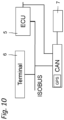
- FIG. 12 shows a schematic block diagram of a communication system of the fertilizer spreader 1.
- FIG Figure 1A The communication system can have a data bus in a manner known per se, e.g. B. a CAN data bus and/or a data bus designed as an ISOBUS. Instead of a data bus, the components can communicate with one another via an Ethernet data network.
- a control device 5, e.g. B. a control unit, an operator terminal 6 (referred to as a terminal in Figure 1C, e.g. an ISOBUS terminal) and a detection device 7 for detecting rows of plants or a grid of rows of plants are in signal connection with the communication system via corresponding data interfaces.
- the operator terminal can also be an operator terminal of the tractor if it is z.
- the fertilizer spreader is a towed fertilizer spreader.
- control device 5 can be set up to change the spreading pattern, preferably for carrying out a belt application, to control the dividing device 15 in order to reduce the number of spreading material - to change sub-streams.
- the control device 5 can have a signal connection with the operating terminal 6 and be set up to generate a control signal depending on information about row spacing entered or stored via the operating terminal 6, preferably for carrying out a belt application and for controlling the dividing device.
- control device 5 can have a signal connection with a detection device 7 for detecting a row of plants or a grid of rows of plants formed by rows of plants.
- the detection device 7 can comprise, for example, a camera (not shown) arranged on the distribution linkage. A position of the distribution devices 10 relative to a row of plants or a grid of rows of plants can also be determined by means of the camera.
- the control device 5 can be set up to generate its control signals as a function of the data recorded by the detection device 7, preferably to carry out a tape application and/or to control the dividing device 15.
- the control device 5 can be set up using the camera data to determine a row spacing or a spacing of a plant row grid and, depending on this, to optionally set either two or three simultaneously generated spreading fans per distribution device 10 by the control device 5 expediently controlling the dividing device 15 for this purpose.
- the first or second band application spreading operation can be set (cf. Figures 2A and 2B ) and with smaller row spacings the third or fourth band application spreading operation (cf. Figures 3A and 3B ) can be set.
- control device 5 it is also possible for the control device 5 to be set up to generate control signals for changing a width and/or position of the impact areas 14 as a function of information on row spacing entered or stored via the operating terminal 6 and as a function of the data recorded by the recording device 7 .
- the baffle plates have an actuator for changing the shape of the baffle surfaces and have a pivoting device to change the pivoted position of the baffle plate relative to the distribution linkage.
- control device 5 it is also possible for the control device 5 to be set up to control the dosing device 8 for dosing the grit into the distribution lines 4 in such a way that the dosing of the grit can be adapted as a function of the variable number of litter compartments.
- each distribution line 4 can be assigned a separate dosing device for grit, so that depending the number of spreading compartments and/or depending on the width of the spreading compartments, the quantity of distribution material metered by means of the metering devices can optionally be adjusted manually (e.g. via the operating terminal 6) and/or automatically.
Landscapes
- Life Sciences & Earth Sciences (AREA)
- Soil Sciences (AREA)
- Environmental Sciences (AREA)
- Fertilizing (AREA)
Applications Claiming Priority (1)
| Application Number | Priority Date | Filing Date | Title |
|---|---|---|---|
| DE102022103794.0A DE102022103794A1 (de) | 2022-02-17 | 2022-02-17 | Pneumatischer Düngerstreuer |
Publications (2)
| Publication Number | Publication Date |
|---|---|
| EP4230019A1 true EP4230019A1 (fr) | 2023-08-23 |
| EP4230019B1 EP4230019B1 (fr) | 2025-11-05 |
Family
ID=85251654
Family Applications (1)
| Application Number | Title | Priority Date | Filing Date |
|---|---|---|---|
| EP23156786.8A Active EP4230019B1 (fr) | 2022-02-17 | 2023-02-15 | Epandeur pneumatique d'engrais |
Country Status (2)
| Country | Link |
|---|---|
| EP (1) | EP4230019B1 (fr) |
| DE (1) | DE102022103794A1 (fr) |
Cited By (1)
| Publication number | Priority date | Publication date | Assignee | Title |
|---|---|---|---|---|
| US20240074346A1 (en) * | 2021-03-11 | 2024-03-07 | Shandong Academy Of Agricultural Machinery Sciences | Multi-crop adaptive seed delivery and uniform seed distribution device |
Citations (4)
| Publication number | Priority date | Publication date | Assignee | Title |
|---|---|---|---|---|
| US20170265379A1 (en) * | 2016-03-18 | 2017-09-21 | 360 Yield Center, Llc | Apparatus and methods for dispensing agricultural products |
| DE102018131070A1 (de) | 2018-12-05 | 2020-06-10 | Horsch Leeb Application Systems Gmbh | Verteilmaschine zum Ausbringen von körnigem landwirtschaftlichem Streugut und Verfahren zur Verteilung von körnigem landwirtschaftlichem Streugut |
| DE102018131073A1 (de) | 2018-12-05 | 2020-06-10 | Horsch Leeb Application Systems Gmbh | Steuerungs- und/oder Regelungssystem für eine landwirtschaftliche Verteilmaschine, landwirtschaftliche Verteilmaschine und Verfahren zur Steuerung- und/oder Regelung einer landwirtschaftlichen Verteilmaschine |
| EP3881660A1 (fr) * | 2020-03-20 | 2021-09-22 | Amazonen-Werke H. Dreyer SE & Co. KG | Dispositif d'épandage agricole |
Family Cites Families (3)
| Publication number | Priority date | Publication date | Assignee | Title |
|---|---|---|---|---|
| FR2605833B1 (fr) | 1986-11-05 | 1990-04-20 | Nodet Gougis | Epandeur de produits granuleux par projection forcee |
| DE102017005093A1 (de) | 2017-05-29 | 2018-11-29 | Rauch Landmaschinenfabrik Gmbh | Pneumatische Verteilmaschine und Verfahren zum Ausbringen von Verteilgut mit derselben |
| DK3881659T3 (en) | 2020-03-20 | 2025-06-30 | Amazonen Werke H Dreyer Se & Co Kg | Method for applying granular material |
-
2022
- 2022-02-17 DE DE102022103794.0A patent/DE102022103794A1/de active Pending
-
2023
- 2023-02-15 EP EP23156786.8A patent/EP4230019B1/fr active Active
Patent Citations (4)
| Publication number | Priority date | Publication date | Assignee | Title |
|---|---|---|---|---|
| US20170265379A1 (en) * | 2016-03-18 | 2017-09-21 | 360 Yield Center, Llc | Apparatus and methods for dispensing agricultural products |
| DE102018131070A1 (de) | 2018-12-05 | 2020-06-10 | Horsch Leeb Application Systems Gmbh | Verteilmaschine zum Ausbringen von körnigem landwirtschaftlichem Streugut und Verfahren zur Verteilung von körnigem landwirtschaftlichem Streugut |
| DE102018131073A1 (de) | 2018-12-05 | 2020-06-10 | Horsch Leeb Application Systems Gmbh | Steuerungs- und/oder Regelungssystem für eine landwirtschaftliche Verteilmaschine, landwirtschaftliche Verteilmaschine und Verfahren zur Steuerung- und/oder Regelung einer landwirtschaftlichen Verteilmaschine |
| EP3881660A1 (fr) * | 2020-03-20 | 2021-09-22 | Amazonen-Werke H. Dreyer SE & Co. KG | Dispositif d'épandage agricole |
Cited By (2)
| Publication number | Priority date | Publication date | Assignee | Title |
|---|---|---|---|---|
| US20240074346A1 (en) * | 2021-03-11 | 2024-03-07 | Shandong Academy Of Agricultural Machinery Sciences | Multi-crop adaptive seed delivery and uniform seed distribution device |
| US12114594B2 (en) * | 2021-03-11 | 2024-10-15 | Shandong Academy Of Agricultural Machinery Sciences | Multi-crop adaptive seed delivery and uniform seed distribution device |
Also Published As
| Publication number | Publication date |
|---|---|
| DE102022103794A1 (de) | 2023-08-17 |
| EP4230019B1 (fr) | 2025-11-05 |
Similar Documents
| Publication | Publication Date | Title |
|---|---|---|
| EP3284332B1 (fr) | Machine de distribution et procédé d'ensemencement de produit granulaire | |
| EP3409090A1 (fr) | Machine d'épandage pneumatique et procédé de distribution de produit à épandre au moyen de ladite machine d'épandage pneumatique | |
| DE9313779U1 (de) | Landwirtschaftliche pneumatische Verteilmaschine | |
| EP4094577B1 (fr) | Pulvérisateur agricole et dispositif pulvérisateur pour un pulvérisateur agricole, ainsi que procédé d' ajustement d' un dispositif pulvérisateur pour une distribution par rangé e du liquide de pulvérisation | |
| DE102018124626A1 (de) | Landwirtschaftliche Verteilvorrichtung und Verfahren zu deren Überführung zwischen einer Arbeitsstellung und einer Transportstellung | |
| CH641318A5 (de) | Streugeraet fuer koerniges und/oder pulveriges gut. | |
| EP0545894B2 (fr) | Epandeur centrifuge | |
| EP4230019B1 (fr) | Epandeur pneumatique d'engrais | |
| EP3991555B1 (fr) | Pulvérisateur agricole et dispositif de pulvérisation pour un pulvérisateur agricole | |
| DE3420617C2 (fr) | ||
| DE2851797C3 (de) | Maschine zum Ausstreuen von körnigem Material | |
| EP4676221A1 (fr) | Dispositif de pulvérisation agricole | |
| EP3881661A1 (fr) | Procédé d'épandage d'une matière granulaire | |
| EP0344647B1 (fr) | Semoir | |
| DE2519760A1 (de) | Maschine zum verteilen von koernigen materialien | |
| EP0392257B1 (fr) | Méthode de distribution d'engrais avec un épandeur centrifuge | |
| WO2020088948A1 (fr) | Ensemble buse de pulvérisation agricole | |
| WO2023072585A1 (fr) | Épandeur pneumatique d'engrais | |
| EP3508047A1 (fr) | Dispositif d'épandage du produit d'épandage sur des surfaces agricoles | |
| DE102023108924A1 (de) | Landwirtschaftliche Feldspritze und Spritzvorrichtung für eine landwirtschaftliche Feldspritze | |
| DE102009012849A1 (de) | Pneumatische Direktsämaschine | |
| DE102021109914A1 (de) | Landwirtschaftliche Feldspritze und Spritzvorrichtung für eine landwirtschaftliche Feldspritze | |
| DE102022121777A1 (de) | Landwirtschaftliche Feldspritze und Spritzvorrichtung für eine landwirtschaftliche Feldspritze sowie Verfahren zur Anpassung einer Spritzvorrichtung für eine reihenbezogene Ausbringung von Spritzflüssigkeit | |
| DE102023105531A1 (de) | Landwirtschaftliche Spritzeinrichtung | |
| DE102023108890A1 (de) | Verfahren und Spritzvorrichtung zum Ausbringen eines Spritzmittels, z. B. mittels einer Band- und/oder Spotapplikation, und insbesondere zur Spritzmittel-Restmengen-Entleerung |
Legal Events
| Date | Code | Title | Description |
|---|---|---|---|
| PUAI | Public reference made under article 153(3) epc to a published international application that has entered the european phase |
Free format text: ORIGINAL CODE: 0009012 |
|
| STAA | Information on the status of an ep patent application or granted ep patent |
Free format text: STATUS: THE APPLICATION HAS BEEN PUBLISHED |
|
| AK | Designated contracting states |
Kind code of ref document: A1 Designated state(s): AL AT BE BG CH CY CZ DE DK EE ES FI FR GB GR HR HU IE IS IT LI LT LU LV MC ME MK MT NL NO PL PT RO RS SE SI SK SM TR |
|
| STAA | Information on the status of an ep patent application or granted ep patent |
Free format text: STATUS: REQUEST FOR EXAMINATION WAS MADE |
|
| 17P | Request for examination filed |
Effective date: 20240207 |
|
| RBV | Designated contracting states (corrected) |
Designated state(s): AL AT BE BG CH CY CZ DE DK EE ES FI FR GB GR HR HU IE IS IT LI LT LU LV MC ME MK MT NL NO PL PT RO RS SE SI SK SM TR |
|
| GRAP | Despatch of communication of intention to grant a patent |
Free format text: ORIGINAL CODE: EPIDOSNIGR1 |
|
| STAA | Information on the status of an ep patent application or granted ep patent |
Free format text: STATUS: GRANT OF PATENT IS INTENDED |
|
| INTG | Intention to grant announced |
Effective date: 20250602 |
|
| GRAS | Grant fee paid |
Free format text: ORIGINAL CODE: EPIDOSNIGR3 |
|
| GRAA | (expected) grant |
Free format text: ORIGINAL CODE: 0009210 |
|
| STAA | Information on the status of an ep patent application or granted ep patent |
Free format text: STATUS: THE PATENT HAS BEEN GRANTED |
|
| AK | Designated contracting states |
Kind code of ref document: B1 Designated state(s): AL AT BE BG CH CY CZ DE DK EE ES FI FR GB GR HR HU IE IS IT LI LT LU LV MC ME MK MT NL NO PL PT RO RS SE SI SK SM TR |
|
| REG | Reference to a national code |
Ref country code: CH Ref legal event code: F10 Free format text: ST27 STATUS EVENT CODE: U-0-0-F10-F00 (AS PROVIDED BY THE NATIONAL OFFICE) Effective date: 20251105 Ref country code: GB Ref legal event code: FG4D Free format text: NOT ENGLISH |
|
| REG | Reference to a national code |
Ref country code: DE Ref legal event code: R096 Ref document number: 502023002118 Country of ref document: DE |
|
| REG | Reference to a national code |
Ref country code: IE Ref legal event code: FG4D Free format text: LANGUAGE OF EP DOCUMENT: GERMAN |
|
| REG | Reference to a national code |
Ref country code: NL Ref legal event code: MP Effective date: 20251105 |
|
| REG | Reference to a national code |
Ref country code: DE Ref legal event code: R081 Ref document number: 502023002118 Country of ref document: DE Owner name: HORSCH LEEB APPLICATION SYSTEMS SE & CO. KG, DE Free format text: FORMER OWNER: HORSCH LEEB APPLICATION SYSTEMS GMBH, 94405 LANDAU, DE |
|
| REG | Reference to a national code |
Ref country code: CH Ref legal event code: W10 Free format text: ST27 STATUS EVENT CODE: U-0-0-W10-W00 (AS PROVIDED BY THE NATIONAL OFFICE) Effective date: 20260318 |
|
| PG25 | Lapsed in a contracting state [announced via postgrant information from national office to epo] |
Ref country code: ES Free format text: LAPSE BECAUSE OF FAILURE TO SUBMIT A TRANSLATION OF THE DESCRIPTION OR TO PAY THE FEE WITHIN THE PRESCRIBED TIME-LIMIT Effective date: 20251105 |
|
| REG | Reference to a national code |
Ref country code: LT Ref legal event code: MG9D |
|
| PG25 | Lapsed in a contracting state [announced via postgrant information from national office to epo] |
Ref country code: NO Free format text: LAPSE BECAUSE OF FAILURE TO SUBMIT A TRANSLATION OF THE DESCRIPTION OR TO PAY THE FEE WITHIN THE PRESCRIBED TIME-LIMIT Effective date: 20260205 |
|
| PG25 | Lapsed in a contracting state [announced via postgrant information from national office to epo] |
Ref country code: FI Free format text: LAPSE BECAUSE OF FAILURE TO SUBMIT A TRANSLATION OF THE DESCRIPTION OR TO PAY THE FEE WITHIN THE PRESCRIBED TIME-LIMIT Effective date: 20251105 Ref country code: HR Free format text: LAPSE BECAUSE OF FAILURE TO SUBMIT A TRANSLATION OF THE DESCRIPTION OR TO PAY THE FEE WITHIN THE PRESCRIBED TIME-LIMIT Effective date: 20251105 |
|
| PGFP | Annual fee paid to national office [announced via postgrant information from national office to epo] |
Ref country code: AT Payment date: 20260301 Year of fee payment: 4 |
|
| RAP4 | Party data changed (patent owner data changed or rights of a patent transferred) |
Owner name: HORSCH LEEB APPLICATION SYSTEMS SE & CO. KG |
|
| PG25 | Lapsed in a contracting state [announced via postgrant information from national office to epo] |
Ref country code: NL Free format text: LAPSE BECAUSE OF FAILURE TO SUBMIT A TRANSLATION OF THE DESCRIPTION OR TO PAY THE FEE WITHIN THE PRESCRIBED TIME-LIMIT Effective date: 20251105 |
|
| PG25 | Lapsed in a contracting state [announced via postgrant information from national office to epo] |
Ref country code: RS Free format text: LAPSE BECAUSE OF FAILURE TO SUBMIT A TRANSLATION OF THE DESCRIPTION OR TO PAY THE FEE WITHIN THE PRESCRIBED TIME-LIMIT Effective date: 20260205 |
|
| PG25 | Lapsed in a contracting state [announced via postgrant information from national office to epo] |
Ref country code: IS Free format text: LAPSE BECAUSE OF FAILURE TO SUBMIT A TRANSLATION OF THE DESCRIPTION OR TO PAY THE FEE WITHIN THE PRESCRIBED TIME-LIMIT Effective date: 20260305 |