EP4230023B1 - Andaineuse rotative - Google Patents
Andaineuse rotative Download PDFInfo
- Publication number
- EP4230023B1 EP4230023B1 EP22157589.7A EP22157589A EP4230023B1 EP 4230023 B1 EP4230023 B1 EP 4230023B1 EP 22157589 A EP22157589 A EP 22157589A EP 4230023 B1 EP4230023 B1 EP 4230023B1
- Authority
- EP
- European Patent Office
- Prior art keywords
- rotary rake
- rotary
- frame
- rake
- cardan shaft
- Prior art date
- Legal status (The legal status is an assumption and is not a legal conclusion. Google has not performed a legal analysis and makes no representation as to the accuracy of the status listed.)
- Active
Links
Images


Classifications
-
- A—HUMAN NECESSITIES
- A01—AGRICULTURE; FORESTRY; ANIMAL HUSBANDRY; HUNTING; TRAPPING; FISHING
- A01D—HARVESTING; MOWING
- A01D78/00—Haymakers with tines moving with respect to the machine
- A01D78/08—Haymakers with tines moving with respect to the machine with tine-carrying rotary heads or wheels
- A01D78/10—Haymakers with tines moving with respect to the machine with tine-carrying rotary heads or wheels the tines rotating about a substantially vertical axis
- A01D78/1057—Drive mechanisms
-
- A—HUMAN NECESSITIES
- A01—AGRICULTURE; FORESTRY; ANIMAL HUSBANDRY; HUNTING; TRAPPING; FISHING
- A01D—HARVESTING; MOWING
- A01D78/00—Haymakers with tines moving with respect to the machine
- A01D78/08—Haymakers with tines moving with respect to the machine with tine-carrying rotary heads or wheels
- A01D78/10—Haymakers with tines moving with respect to the machine with tine-carrying rotary heads or wheels the tines rotating about a substantially vertical axis
- A01D78/1028—Pivotable rotor support arms
Definitions
- the present invention relates to a rotary swather for gathering crops lying on a field or meadow area, such as hay, straw or green waste, according to the preamble of patent claim 1.
- Such rotary rakes are well known. They have a frame that extends essentially in the direction of travel, which is supported on the ground by a chassis and which can be coupled to a traction and drive machine at a front end. At least one rotary rake is hinged to the frame by means of a support arm. The support arm is mounted on the frame so that it can pivot about a support arm pivot axis and, together with the rotary rake attached to it, can be raised into a transport position and lowered into a working position.
- the rotary rake can usually be driven via a drive train that has an overhead shaft in connection with a gearbox and is connected to the traction and drive machine via a drive shaft.
- the EP 3 430 884 A1 describes a rotary rake which comprises a frame extending in the direction of travel and working, on which a front-side coupling device for coupling to an agricultural tractor and drive machine and a chassis for support on the ground are provided. At least one rotary rake is arranged on each side of the frame, which is driven in rotation about a vertical central axis and can be transferred from a working position parallel to the ground to an almost vertical transport position and back via a length-adjustable support arm.
- the respective support arms are pivotally mounted on the frame about a support arm pivot axis inclined at an acute angle to a horizontal plane.
- the rotary rakes are driven via a drive train which has a drive shaft arrangement, at least one transfer case and a rotary joint shaft extending from the transfer case to a respective rotary rake.
- the drive train is connected to a tractor and drive machine via a connected drive shaft.
- the transfer case is attached to the frame in a position above the rotary rakes with a distance of 30% to 75% of the outer diameter of the rotary rake in front of the central axis of the rotary rake.
- the angle of inclination of the support arm pivot axis is limited to a range of 5° to 15°.
- the angle of inclination of the support arm pivot axis is designed in such a way that the quotient of the change in length of the rotary joint shaft and the size of the required change in height does not exceed a predetermined limit.
- the transmission of high speeds from the tractor and drive unit to the rotary rake causes vibrations, which can lead to high wear on the drive train. Furthermore, the change in height of the rotary rakes compared to the chassis of the rotary rake, which is necessary when guiding the rotary rakes over the uneven ground of the field or meadow, causes a change in the length of the rotary universal joint shafts, which takes place under the influence of transmitted torque and has a negative effect on ground adaptation.
- the invention is based on the object of creating a rotary rake which has low wear of the drive train and improved ground adaptation.
- a rotary rake has a frame extending in the direction of travel, which can be coupled to an agricultural tractor and drive machine at the front via a hitch point of a connecting device, for example a bolt coupling, a hitch hook, a ball head coupling or the like.
- the frame has a chassis for support on the ground.
- a first rotary rake and a second rotary rake are arranged on both sides of the frame in the transverse direction, with a central axis of the first rotary rake being arranged in the longitudinal direction of the frame between the hitch point and a central axis of the second rotary rake.
- the first rotary rake is connected via a first support arm and the second
- the rotary rake is pivotally mounted on the frame via a second support arm, with each rotary rake being operatively connected to a drive train to drive it.
- the drive train can be connected to an output of the tractor and drive machine via a PTO connection point by means of a drive universal joint shaft.
- the drive train has a connecting universal joint shaft arrangement that is connected to a transfer case.
- the drive train has a connecting universal joint shaft that connects a first transfer case to a second transfer case, in particular without a vertical angular offset.
- the transfer cases are attached to the frame above the rotary rakes, with the first transfer case being connected to the first rotary rake via a first rotary universal joint shaft and the second transfer case being connected to the second rotary rake via a second rotary universal joint shaft.
- the rotary universal joint shafts are designed to be variable in length.
- the rotary universal joint shafts can, for example, be designed with sliding profile parts that change the length of the rotary universal joint shafts by changing their overlap. This contributes to the ground adaptation of the rotary rakes in relation to the chassis of the rotary rake and enables the rotary universal joint shafts to transfer the rotary rakes from an almost vertical transport position to an almost horizontal working position and vice versa. This is particularly true for adjustable-length support arms for adjusting the working width.
- the second transfer case is arranged in the longitudinal direction of the frame between the hitch point and the first transfer case, and the PTO connection point is connected to the second transfer case via a connecting universal joint arrangement.
- the second transfer case which is assigned to the rear second rotary rake, is arranged in the longitudinal direction of the frame between the hitch point and the first transfer case, which is assigned to the front first rotary rake.
- the first transfer case which is assigned to the front rotary rake
- the first transfer case can thus be regarded as the rear transfer case and the second transfer case as the front transfer case.
- the drive train's connecting shaft assembly is connected to the drive shaft on the drive side via the PTO connection point and to the front, second transfer case on the output side.
- the connecting shaft assembly has the task of transmitting torque from the drive shaft to the second transfer case.
- the frame viewed in the longitudinal direction, offers a large amount of play or space for connecting the rear transfer case, which drives the front rotary rake, behind the front transfer case, which drives the front rotary rake. This allows for a great deal of flexibility in positioning the front and rear transfer cases.
- the PTO connection point can be set to almost the same height as a PTO of the tractor and drive machine and yet the gradient between the PTO connection point and the front transfer case can be small, while the distance between the attachment point and the front end of the rotary rake can still be short.
- the front drive train connected to the drive shaft i.e. the connection shaft arrangement, advantageously has little wear and tear while the front frame is as compact as possible.
- the first rotary joint shaft and the second rotary joint shaft extend at an angle to the frame to the rotary rakes assigned to them.
- the first, rear transfer case is arranged longitudinally well behind the first rotary rake.
- the first rotary joint shaft extends from the back to the front.
- the second rotary joint shaft is led to the second rotary rake from the second, front transfer case, which is arranged longitudinally well in front of the second rotary rake.
- the rotary joint shafts form an acute angle with the frame in a horizontal plane parallel to the ground and in a vertical longitudinal plane of the frame, whereby the angle can be very small.
- the smaller necessary change in the length of the rotary joint shafts is particularly important for variable-length support arms when the support arm extension is smaller in the transport position than in the working position. Transferring the rotary rakes from an almost vertical transport position, in which the length of the support arms should only be very short due to the low permissible transport height, to a working position in which the support arms and thus the rotary rakes have a wider projection in the transverse direction of the frame, only involves a small change in the length of the rotary joint shafts.
- the distance between the transfer case and the rotary rake, which is connected to it via a rotary joint shaft means that the rotary joint shaft in question can have a large change in length that exceeds the change in length required when moving the rotary rake from the working position to the transport position and vice versa.
- the rotary joint shafts can have as short a length as possible with maximum overlap of the sliding profile parts in order to keep the height of the rotary rake low.
- the necessary change in length of the rotary joint shafts is kept small by the acute angle to the frame.
- the actual change in the overlap of the sliding profile parts is significantly smaller than the greatest possible extension length of the sliding profile parts, which have a necessary minimum overlap of 8% to 10% in particular.
- the first support arm and the second support arm are preferably designed to be variable in length.
- the support arms can, for example, be telescopic and/or designed with additional pivot axes in order to achieve a large raking width or working width of the rotary swather.
- the support arms can, for example, each comprise a first element and a second element, the first element being pivotally mounted on the frame in order to be able to move the respective support arm between the working position and the transport position, in which the rotary swather has a compact, folded configuration.
- the first element can be pivotally or telescopically connected to the second element, to which the rotary rake is hinged, so that in the lowered working position a working width of the rotary swather can be changed by extending the support arms and can, for example, be increased to a maximum working width. Large working widths can therefore be achieved with a small transport dimension.
- the rotary joint shafts can be changed in length to such an extent that they enable the rotary rake to adapt reliably to the ground when the respective rotary rake is in the lowered working position and the support arm is fully extended. This means that the rotary joint shaft offers sufficient buffering even in a depression to prevent it from falling apart.
- the support arm pivot axes can preferably be aligned, in particular horizontally, in the longitudinal direction of the frame.
- a reliable mode of operation can also be realized with a horizontally positioned support arm pivot axis, in a structurally simple manner.
- the support arm pivot axes are preferably arranged at the same vertical height as the connecting universal joint shaft. This means that the universal joint shafts and the support arms are essentially in the same pivot plane.
- the PTO connection point is located in the longitudinal direction of the frame behind the hitch point and is arranged at a horizontal distance from the nearest transfer case, wherein the horizontal distance is greater than the radius of the first rotary rake. Furthermore, the PTO connection point is arranged vertically above the hitch point and has a height offset from the nearest transfer case, whereby a gradient is set.
- the large distance between the PTO connection point and the nearest second transfer case means that the pitch, and thus the angular offset of the connecting universal joint arrangement, can be selected within a wide range.
- the angular offset should be as small as possible and should not exceed 25° under any circumstances, as this would result in considerable wear on the connecting universal joint arrangement.
- the minimum angle resulting from the minimum pitch is only between 5° and 15°, in particular around 10°.
- a limitation of a transmission angle of the connecting universal joint arrangement downwards does not result from the position of the next transfer case, but at most from a necessary clearance height on the frame at the front end of the front rotary rake.
- the distance between the transfer case and the rotary rake associated with it can therefore be increased in the arrangement according to the invention without this having a significant effect on the minimum angle of the connecting universal joint arrangement. Even with a large distance or a small angle between the rotary universal joint shaft and the frame, a transmission angle of the connecting universal joint arrangement of less than 23° in particular can be achieved and the PTO connection point can still be approximately at the height of the tractor's PTO shaft.
- the second transfer case is arranged in the longitudinal direction of the frame between the center axes of the first rotary rake and the second rotary rake.
- the rotary rake according to the invention Since the second transfer case is arranged behind the center axis of the first rotary rake, in particular behind the first support arm, the rotary rake according to the invention has a large distance between the PTO connection point and the front transfer case and thus a small minimum gradient.
- the small minimum gradient results in a small minimum angular offset of the connecting universal joint arrangement. This means that the drive train can be designed to be low in wear.
- the first transfer case is arranged in the longitudinal direction of the frame between the respective center axes of the first rotary rake and the second rotary rake.
- the center axis of the first rotary rake and the center axis of the second rotary rake are arranged at a distance from each other over a center axis distance.
- the first transfer case and the second transfer case are arranged at a maximum distance from each other over the center axis distance.
- the frame between the attachment point and the first rotary rake can have a length of approximately 50% to 75% of the rotary rake diameter, in particular 1.5 m to 1.6 m. This corresponds approximately to the minimum distance at which turning is possible with conventional tractors is still reliably collision-free. Due to the arrangement according to the invention, this minimum distance does not have to be exceeded, even if there is a large distance between the transfer cases and the center axes of the rotary rakes assigned to them, in particular more than 50% of the rotary rake diameter.
- the respective center axes are arranged at a distance from one another that is 1 to 1.5 times the length of the radius of the first rotary rake.
- the center axis distance is small. This advantageously allows the frame to have a particularly compact design.
- the first transfer case and the second transfer case are each arranged with an extension that is 50% to 75% of the outer diameter of the first rotary rake, spaced apart from the center axis of the rotary rakes that are in operative connection with them.
- the variable-length rotary universal joint shafts can have the shortness required for the transport position on the one hand and the length required for the working position on the other, in particular with the support arm fully extended.
- the acute angle formed in the horizontal or ground-parallel plane and in the vertical longitudinal plane of the frame between the respective rotary joint shaft and the frame in the working position is small, both when the support arm is not extended and when the support arm is fully extended.
- the smaller the acute angle, in particular the acute angle in the horizontal plane the smaller the required change in length of the respective rotary joint shaft in the working position of the rotary rake in order to compensate for a required change in height of the rotary rake compared to the chassis of the rotary rake when the rotary rake is guided along the uneven ground of the field or meadow, especially when the support arm is extended.
- the ground adaptation of the rotary rake is improved because a change in length of the rotary joint shafts, which is caused in particular by a change in length in the overlap of sliding profile parts, is carried out under the influence of transmitted torque, which results in frictional forces between the sliding profile parts. This means that wear is reduced due to a shorter extension path of the rotary joint shaft during ground adaptation.
- the connecting universal joint arrangement is formed by a substantially one-piece connecting universal joint shaft.
- the one-piece connecting universal joint shaft bridges a large installation length between the power take-off shaft connection point and the second transfer case, the connection being accompanied by a small transmission angle.
- the connecting propeller shaft arrangement has a two-part arrangement, wherein a first propeller shaft part forms the PTO shaft connection point and comprises a second propeller shaft part connected to the first propeller shaft part, which is connected to the second transfer case.
- the first cardan shaft part and the second cardan shaft part are connected in particular via a simple cardan joint and enclose a working angle.
- the two-part connecting shaft arrangement advantageously allows the gradient between the PTO connection point and the second transfer case to extend over a small horizontal longitudinal extent. This means that the clearance height of the first rotary rake can be overcome quickly, i.e. over a short horizontal extension in the longitudinal direction of the frame, only via an increase in the first part of the universal joint shaft.
- the second part of the universal joint shaft is connected to the second transfer case in particular without an angular offset.
- the first propeller shaft part forms a transmission angle of around 20°. It reaches the height of the transfer case at a bend point.
- the transfer cases each have a connection distance that is defined as the distance between the joint axis of the transmission input and the center of the transfer case.
- the center of the transfer case is approximately at the intersection point of the transmission input center axis and the center axis of the transmission output, to which the rotary propeller shaft is connected.
- the distance of the bending point from the center axis of the front rotary rake minus the connection distance of the first transfer case is less than the distance of the gear center of the first transfer case from the center axis of the first rotary rake.
- the transmission center of the first transfer case is further away from the center axis of the first transfer case than the kink point.
- a Z-connection of the drive train with the tractor and drive machine is realized.
- the second part of the drive shaft moves approximately in a horizontal plane parallel to the ground.
- the Z-connection of the rotary rake has approximately the same spatial working angle in the front drive train, in particular 20°, so that there is uniformity in the transmission of rotary motion and pronounced speed fluctuations in the transmission are avoided or prevented. This makes it advantageously possible to use a low-maintenance standard drive shaft / single drive shaft with simple joints in the drive shaft arrangement, compared to a maintenance-intensive wide-angle drive shaft.
- a low-maintenance standard universal joint shaft is preferably used for evenly transmitted rotary movements, i.e. the standard universal joint shaft is preferably arranged parallel to the axis and moves in the horizontal plane and its respective joints have the same working angles.
- a standard universal joint shaft can have a joint on the side of the tractor and drive machine and on the side of the working machine with a working angle of up to 25°, whereby the angles of the respective joints can vary by up to 7°. Even small differences between the working angles of the joints, especially more than 7°, can prematurely damage or destroy the joints considerably due to uneven transmission of rotary movements. Short-term working angles between 25° and 40°, for example when cornering, are possible with reduced transmission of rotary movements, for example 40% of the rated power, without causing significant damage.
- wide-angle universal joints which require more maintenance, can be used as the drive universal joint. These can, for example, transmit higher power at a maximum working angle of 25°. If, for example, a drive universal joint with a wide-angle constant velocity joint and a single joint is installed between the tractor and drive machine and the rotary rake, irregularities in movement can be prevented in continuous operation by not exceeding an angle difference of 16° at 540 min -1 and/or 9° at 1,000 min -1 . For short periods, for example when cornering, wide-angle universal joints can, depending on the type of joint, allow angular mobility between 50° and 80° without generating torsional vibrations.
- a Z-connection with the drive universal joint shaft is realized, whereby the drive universal joint shaft maintains an arrangement that is almost parallel to the ground during operation. It connects the tractor and drive machine to the rotary rake with almost no vertical angle, so that the spatial working angles between the drive universal joint shaft, the first universal joint shaft part and the second universal joint shaft part are almost the same. In this way, pronounced speed fluctuations between the drive universal joint shaft and the second universal joint shaft part are prevented and the uniformity in the transmission of the rotary motion is improved.
- the first universal joint part can be mounted on the frame via a first bearing point.
- the end of the first universal joint part facing the tractor forms the power take-off connection point to which a drive universal joint shaft can be connected for connection to the power take-off of the tractor.
- the second universal joint part is mounted on the frame between the PTO shaft connection point and the center axis of the first rotary rake via a second bearing point.
- the first universal joint part and the second universal joint part enclose an angle, in particular a fixed angle.
- the bending point is spaced apart from the center axis of the first rotary rake by a bending point distance in the longitudinal direction of the frame, with the bending point distance approximately corresponding to the length of the radius of the first rotary rake.
- the position of the bending point influences a length of the first drive shaft part and the second drive shaft part. The smaller the bending point distance, the longer the first drive shaft part and the smaller its transmission angle while the length of the frame remains the same.
- the first rotary rake and the second rotary rake can be driven in opposite directions, with the second rotary rake in particular having a gearbox.
- the gearbox is connected to the drive train via the second rotary universal joint shaft and can adjust the torque, power and direction of rotation of the second rotary rake. Due to the opposite direction of rotation and movement of the rotary rakes, depending on the amount of crop lying on the ground, the first rotary rake and the second rotary rake can, for example, each lay down a swath of crop when there are large amounts of crop, or lay down a single central swath when there are smaller amounts of crop. This enables a large area output.
- the first rotary rake and the second rotary rake are driven in the same direction.
- the first rotary rake at the front in the direction of travel can rake the crop to the second rotary rake behind it, for example to lay down a single side swath.
- a rotary rake 10 for raking crops lying on a field or meadow, such as hay, straw or green waste, is shown in a side view in the working position A.
- the rotary rake 10 has a first rotary rake 14 with a central axis M1 on one side of a frame 12 in the transverse direction QR and a second rotary rake 16 with a central axis M2 on the other side.
- Rake tines 18 are attached to the rotary rakes 14, 16, which are driven around the respective central axes M1, M2 in the approximately horizontal working position of the rotary rakes 14, 16.
- the rotary rakes 14, 16 are arranged at a distance from each other by a central axis distance MM.
- the central axis distance MM is between one and one and a half times the length of the radius R of the first rotary rake 14.
- the frame 12 has a coupling device at the front in the direction of travel F, which is not described in detail here, which has a hitch point 20 for hitching to an agricultural traction and drive machine in the form of a tractor.
- the frame 12 has a chassis 22 with running wheels 24 for support on a field or meadow area.
- a support and feeler wheel arrangement 26 is arranged under the two rotary rakes 14, 16, which ensures the correct working height of the rake tines 18. During operation, this results in a change in the vertical distance of the rotary rakes 14, 16 to the frame 12 due to uneven ground.
- the first rotary rake 14 is articulated to the frame 12 via a first support arm 28 and the second rotary rake 16 is articulated to the frame 12 via a second support arm 30, the first rotary rake 14 being pivotably mounted on the frame 12 via a first support arm pivot axis S1 and the second rotary rake 16 via a second support arm pivot axis S2.
- the support arm pivot axes S1, S2 extend in the longitudinal direction LR of the frame 12, ie they are arranged essentially parallel to the frame 12 and parallel to the ground. In the working position A, the first rotary rake 14 and the second rotary rake 16 are aligned essentially parallel to the ground.
- the respective support arms 28, 30 can be pivoted upwards, for example by means of a hydraulic cylinder arrangement 31 (not shown in detail here) arranged on the support arms 28, 30.
- the support arms 28, 30 are designed to be variable in length, so that a large working width can advantageously be achieved with the rotary rake 10. Due to the variable-length support arms, the first rotary rake 14 and the second rotary rake 16 can be positioned differently in the transverse direction QR of the frame 12, whereby the swath deposit can be changed. This can then take place on both sides, as a central swath or as a one-sided side swath.
- the support arms 28, 30 are regularly set in the shortest configuration.
- the rotary rakes 14, 16 are operatively connected to a drive train 32.
- the course of the drive train 32 is indicated with a dot-dash line and is shown in Fig. 3a and Fig. 3b described in more detail.
- the connection line 32 has a connection universal joint arrangement 34, which is connected on the drive side via a power take-off connection point 36 to a drive universal joint shaft 38, wherein the drive universal joint shaft 38 can be connected to the tractor and drive machine and is arranged in particular horizontally during operation.
- the connecting universal joint arrangement 34 is connected to a second transfer case 44, which in turn is connected to a connecting universal joint shaft 40, which connects the second transfer case 44 to a first transfer case 42.
- the transfer cases 42, 44 are arranged in the vertical direction above the rotary rakes 14, 16 on the frame 12, in particular at the same vertical height, wherein they have a height offset HV to the PTO connection point 36.
- the second transfer case 44 is arranged at a distance HA from the PTO connection point 36. This results in a minimum pitch in the connecting universal joint arrangement 34, so that it must transmit a torque transmission with at least a minimum angular offset.
- the first rotary rake 14 is connected to the first transfer case 42 via a first rotary universal joint shaft 46 and the second rotary rake 16 is connected to the second transfer case 44 via a second rotary universal joint shaft 48.
- the respective rotary universal joint shafts 46, 48 are designed to be variable in length, for example by means of overlapping sliding profiles. This enables the rotary universal joint shafts 46, 48 to be able to transfer the rotary rakes 14, 16 from the almost horizontal working position A with the support arms 28, 30 extended to the almost vertical transport position with the support arms 28, 30 retracted and vice versa. Furthermore, this improves the ground adaptation of the rotary rakes 14, 16 of the rotary swather 10.
- the second transfer case 44 is arranged in the longitudinal direction LR of the frame 12 between the hitch point 20 and the first transfer case 42.
- the second transfer case 44 can be referred to as the front transfer case and the first transfer case 42 as the rear transfer case.
- the two transfer cases 42, 44 are arranged between the center axis M1 of the first rotary rake 14 and the center axis M2 of the second rotary rake 16.
- the first transfer case 42 is arranged in the longitudinal direction LR of the frame 12 behind the center axis M2 of the second rotary rake 16.
- the arrangement of the first transfer case 42 according to the invention in the direction of travel F and the longitudinal direction LR of the frame 12 behind the second transfer case 44 results in a high degree of flexibility in the arrangement of the transfer cases 42, 44 on the frame 12. This makes it possible to achieve a large distance between the hitch point 20 and the second transfer case 44 closest to it in the longitudinal direction LR of the frame 12. This leads to a reduction in the space available in the front drive train 32 in the longitudinal direction LR of the frame 12 between the hitch point 20 and the front or second transfer case 44, so that the connecting universal joint arrangement 34 can have a slight gradient when the length of the frame 12 remains unchanged.
- the first rotary joint shaft 46 is guided from the first transfer case 42 in a position above and behind the first rotary rake 14 and the second rotary joint shaft 48 is guided from the second transfer case 44 in a position above and in front of the second rotary rake 16, wherein the rotary joint shafts 46, 48 run obliquely to the frame 12 in the horizontal and vertical plane.
- Transferring the rotary rakes 14, 16 from the working position A to the transport position and vice versa is accompanied by a change in the length of the rotary joint shafts 46, 48.
- the rotary joint shafts 46, 48 In the transport position, the rotary joint shafts 46, 48 have a length at which the telescopic sliding profile parts are almost completely pushed into one another, whereas the rotary joint shafts 46, 48 are almost completely pulled apart, particularly when the support arms 28, 30 are extended.
- the available extension length of the rotary joint shafts 46, 48 enables the rotary rakes 14, 16 to be transferred into the approximately horizontal working position.
- the arrangement of the transfer cases 42, 44 according to the invention enables such a large change in the length of the rotary joint shafts 46, 48, despite a small transmission angle ⁇ of the connecting joint shaft arrangement 34, that even in working position A with the support arms 28, 30 extended to the maximum, height changes of the respective rotary rakes 14, 16 due to depressions can still be realized by the rotary joint shafts 46, 48.
- This enables large raking widths of the rotary swather 10 with good ground adaptation without the rotary joint shafts 46, 48 threatening to fall apart in depressions or locking in the transport position.
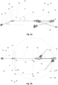
- Fig. 2 shows the rotary rake 10 in a view from above to Fig. 1 .
- a first, front rotary rake 14 and a second, rear rotary rake 16 are arranged on both sides, which are spaced apart from one another by a center axis distance MM which is between 1x and 1.5x radius R of the first rotary rake 14.
- the first rotary rake 14, which is connected to the frame via the first support arm 28, is located in front of the second rotary rake 16, which is pivotally connected to the frame 12 via the second support arm 30.
- the respective support arm pivot axes S1, S2 extend almost parallel to the ground in the longitudinal direction LR of the frame 12.
- the two rotary rakes 14, 16 are aligned parallel to the ground in the lowered working position A.
- the rotary rakes 14, 16 can be pivoted up into an approximately vertical transport position.
- the support arms 28, 30 are designed to be adjustable in length, for example telescopic and/or with additional Pivot axes.
- the support arms 28, 30 are shown here in their maximum extension.
- the rotary joint shafts 46, 48 are also designed to be variable in length.
- the second, front transfer case 44 is arranged in the longitudinal direction LR of the frame 12 between the hitch point 20 and the first, rear transfer case 42.
- the first, rear transfer case 42 is connected accordingly to the first, front rotary rake 14 and the second, front transfer case 44 to the second, rear rotary rake 16.
- first rotary joint shaft 46 extends from the first transfer case 42 in an obliquely forward and outward orientation to the first rotary rake 14 and the second rotary joint shaft 48 extends from the second transfer case 44 in an obliquely rearward and outward orientation to the second rotary rake 16.
- the rotary joint shafts 46, 48 and the frame 12 enclose an acute angle ⁇ , particularly in the horizontal plane, which is small due to the large distance between the transfer cases 42, 44 and the rotary rakes 14, 16 connected to them.
- the arrangement according to the invention of the first transfer case 42 in the direction of travel F and the longitudinal direction LR of the frame 12 behind the second transfer case 44 enables a high degree of flexibility in the arrangement of the transfer cases 42, 44 on the frame 12, whereby a large distance L1 can be achieved between the center axis M1 of the rotary rake 14 and the first transfer case 42.
- the distance L2 between the center axis M2 of the second rotary rake 16 and the second transfer case 44 results analogously.
- the distances L1 and L2 are preferably between 100% and 150% of the radius R of the rotary rake 14, 16. The greater the distance L1, L2, the smaller the relative angular movement and the relative extension length of the rotary universal joint shafts 46, 48 during operation.
- the arrangement of the transfer cases 42, 44 according to the invention advantageously makes it possible to design the rotary joint shafts 46, 48 with a significantly larger extension path, since the length of the rotary joint shafts 46, 48 and thus also the realizable extension path increases with increasing length L1, L2.
- the space conditions of the front drive train 32 between the attachment point 20 and the front transfer case 44 are equalized in the longitudinal direction LR of the frame 12, whereby the connecting universal joint arrangement 34 has the smallest possible gradient while the length of the frame 12 remains unchanged.
- Fig. 3a shows a representation of the drive train 32, via which the rotary rakes 14, 16 are driven.
- the drive train 32 has a power take-off connection point 36, via which a drive universal joint shaft 38 can be connected, which is essentially horizontal, particularly during operation and is not shown here.
- the drive train 32 comprises the connecting universal joint shaft arrangement 34, which is here designed in two parts and is connected via the second transfer case 44 to the connecting universal joint shaft 40, which in turn drives the first transfer case 42.
- the first transfer case 42 is connected to the first rotary universal joint shaft 46 for driving the first rotary rake 14 and the second transfer case 44 is connected to the second rotary universal joint shaft 48 for driving the second rotary rake 16.
- the connecting universal joint arrangement 34 comprises a first universal joint part 50 and a second universal joint part 52, wherein the first universal joint part 50 encloses a transmission angle a with the horizontal and the second universal joint part 52 which is parallel to the horizontal.
- the first cardan shaft part 50 is mounted on the frame 12 via a first bearing point 54 and the second cardan shaft part 52 via a second bearing point 56.
- the second bearing point 56 is arranged in the longitudinal direction LR of the frame 12 via a bearing distance LA to the center axis M1 of the first rotary rake 14, wherein the bearing distance LA corresponds approximately to the length of the radius R of the first rotary rake 14, as can be seen from Fig. 1 and Fig. 2 can be clearly seen.
- the first cardan shaft part 50 can thus quickly overcome a clearance height D of the first rotary rake 14 under the frame 12 by means of an incline.
- Fig. 3b shows a plan view of the drive train 32 according to Fig. 3a .
- the connecting PTO shaft arrangement 34 has a two-part arrangement, wherein a first PTO part 50 forms the PTO connection point 36 and comprises a second PTO part 52 connected to the first PTO part 50, which is connected to the second transfer case 44.
- the transfer cases 42, 44 each have a connection distance AA.
- the distance AA is defined between the joint axis GA of the transmission input and the center MG of the transfer case 42.
- the center MG of the transfer case 42 is located approximately at the intersection point of the transmission input center axis and the center axis of the transmission output, to which the rotary joint shaft 46 is connected.
- the distance A1 of the bending point KP from the center axis M1 of the front rotary rake 14 minus the connection distance AA of the first transfer case 42 is less than the distance A2 of the transmission center MG of the first transfer case 42 from the center axis M1 of the first rotary rake 14.
Landscapes
- Life Sciences & Earth Sciences (AREA)
- Environmental Sciences (AREA)
- Agricultural Machines (AREA)
Claims (15)
- Andaineuse rotative (10), comprenant un cadre (12) s'étendant dans le sens de la marche (FR), qui peut être accouplé sur le côté avant à une machine de traction et d'entraînement agricole par l'intermédiaire d'un point d'attelage (20) et présente un châssis (22) destiné à être en appui sur le sol, dans laquelle un premier râteau rotatif (14) et un deuxième râteau rotatif (16) sont disposés des deux côtés sur le cadre (12) dans la direction transversale (QR), dans laquelle un axe médian (M1) du premier râteau rotatif (14) est disposé dans la direction longitudinale (LR) du cadre (12) entre le point d'attelage (20) et un axe médian (M2) du deuxième râteau rotatif (16), dans laquelle le premier râteau rotatif (14) par l'intermédiaire d'un premier bras de support (28) et le deuxième râteau rotatif (16) par l'intermédiaire d'un deuxième bras de support (30), qui sont montés sur le cadre (12) respectivement de manière à pouvoir pivoter autour d'un axe de pivotement de bras de support (S1, S2), dans laquelle pour l'entraînement des râteaux rotatifs (14, 16) ceux-ci sont respectivement en liaison fonctionnelle avec une chaîne cinématique (32), qui peut être reliée à une sortie de la machine de traction et d'entraînement au moyen d'un arbre à cardan d'entraînement (38) par l'intermédiaire d'un point de raccordement de prise de force (36), dans laquelle la chaîne cinématique (32) présente un arbre à cardan de liaison (40), qui relie une première boîte de transfert (42) à une deuxième boîte de transfert (44), qui sont placées sur le cadre (12) au-dessus des râteaux rotatifs (14, 16), et dans laquelle la première boîte de transfert (42) est reliée au premier râteau rotatif (18) par l'intermédiaire d'un premier arbre à cardan rotatif (32) et la deuxième boîte de transfert (44) est reliée au deuxième râteau rotatif (20) par l'intermédiaire d'un deuxième arbre à cardan rotatif (36), caractérisée en ce que la deuxième boîte de transfert (44) est disposée dans la direction longitudinale (LR) du cadre (12) entre le point d'attelage (20) et la première boîte de transfert (42) et le point de raccordement de prise de force (36) est relié à la deuxième boîte de transfert (44) par l'intermédiaire d'un ensemble d'arbre à cardan de raccordement (34).
- Andaineuse rotative selon la revendication 1, caractérisée en ce que le premier bras de support (28) ainsi que le deuxième bras de support (30) sont réalisés de manière réglable en longueur.
- Andaineuse rotative selon l'une quelconque des revendications précédentes 1 à 2, caractérisée en ce que les axes de pivotement de bras de support (S1, S2) s'étendent horizontalement dans la direction longitudinale (LR) du cadre (12).
- Andaineuse rotative selon l'une quelconque des revendications précédentes 1 à 3, caractérisée en ce que le point de raccordement de prise de force (36) dans la direction longitudinale (LR) du cadre (12) se situe derrière le point d'attelage (20) et est disposé de manière espacée horizontalement de la boîte de transfert (44) la plus proche, dans laquelle l'écart horizontal (HA) est plus grand que le rayon (R) du premier râteau rotatif (14), et en outre le point de raccordement de prise de force (36) est disposé dans la direction verticale au-dessus du point d'attelage (20) et présente un décalage en hauteur (HV) par rapport à la boîte de transfert (44) la plus proche, ce qui a pour effet qu'une pente apparaît.
- Andaineuse rotative selon l'une quelconque des revendications 1 à 4, caractérisée en ce que la deuxième boîte de transfert (44) dans la direction longitudinale (LR) du cadre (12) est disposée entre les axes médians (M1, M2) du premier râteau rotatif (14) et du deuxième râteau rotatif (16).
- Andaineuse rotative selon la revendication 5, caractérisée en ce que la première boîte de transfert (42) dans la direction longitudinale (LR) du cadre (12) est disposée entre les axes médians (M1, M2) du premier râteau rotatif (14) et du deuxième râteau rotatif (16).
- Andaineuse rotative selon l'une quelconque des revendications 5 ou 6, caractérisée en ce que les axes médians (M1, M2) respectifs sont disposés de manière espacée les uns des autres sur une étendue qui est égale à 1 fois à 1,5 fois la longueur du rayon (R) du premier râteau rotatif (14).
- Andaineuse rotative selon l'une quelconque des revendications 5 à 7, caractérisée en ce que la première boîte de transfert (42) ainsi que la deuxième boîte de transfert (44) sont disposées de manière espacée de l'axe médian (M1, M2) des râteaux rotatifs (14, 16) respectivement en liaison fonctionnelle avec ceux-ci, respectivement avec une étendue qui est égale à 50 % à 75 % du diamètre extérieur du premier râteau rotatif (14).
- Andaineuse rotative selon l'une quelconque des revendications 1 à 8, caractérisée en ce que le point de raccordement de prise de force (36) est relié à la deuxième boîte de transfert (44) directement par l'intermédiaire d'un ensemble d'arbre à cardan de raccordement (34).
- Andaineuse rotative selon la revendication 9, caractérisée en ce que l'ensemble d'arbre à cardan de raccordement (34) est réalisé d'une seule pièce.
- Andaineuse rotative selon la revendication 10, caractérisée en ce que l'ensemble d'arbre à cardan de raccordement (34) est réalisé en deux parties, dans laquelle une première partie d'arbre à cardan (50) est reliée au point de raccordement de prise de force (36) et une deuxième partie d'arbre à cardan (52) à la deuxième boîte de transfert (44), dans laquelle la première partie d'arbre à cardan (50) et la deuxième partie d'arbre à cardan (52) forment un angle qui est en particulier inférieur à 23°, en particulier égal à 20°.
- Andaineuse rotative selon la revendication 11, caractérisée en ce que la première partie d'arbre à cardan (50) est montée sur le cadre (12) par l'intermédiaire d'un premier point d'appui (54) et/ou que la deuxième partie d'arbre à cardan (52) est montée sur le cadre (12) entre le point de raccordement de prise de force (36) et l'axe médian (M1) du premier râteau rotatif (14) par l'intermédiaire d'un deuxième point d'appui (56).
- Andaineuse rotative selon l'une quelconque des revendications 11 à 12, caractérisée en ce que la première partie d'arbre à cardan (50) et la deuxième partie d'arbre à cardan (52) sont reliées par l'intermédiaire d'un point de flexion (KP), dans laquelle la première boîte de transfert (42) possède un écart de connexion (AA), qui est défini par la distance par rapport à l'axe d'articulation (GA) de l'entrée de boîte et le centre (MG) de la boîte de transfert (42), vu dans la direction longitudinale (LR), l'écart (A1) du point de flexion (KP) par rapport à l'axe médian (M1) du râteau rotatif (14) avant moins l'écart de connexion (AA) de la première boîte de transfert (42) est inférieur à l'écart (A2) du milieu de boîte (MG) de la première boîte de transfert (42) par rapport à l'axe médian (M1) du premier râteau rotatif (14).
- Andaineuse rotative selon l'une quelconque des revendications 1 à 13, caractérisée en ce que le premier râteau rotatif (14) et le deuxième râteau rotatif (16) sont entraînés en sens contraire, dans laquelle le deuxième râteau rotatif (16) présente en particulier une boîte.
- Andaineuse rotative selon l'une quelconque des revendications 1 à 14, caractérisée en ce que le premier râteau rotatif (14) et le deuxième râteau rotatif (16) sont entraînés dans le même sens.
Priority Applications (1)
| Application Number | Priority Date | Filing Date | Title |
|---|---|---|---|
| EP22157589.7A EP4230023B1 (fr) | 2022-02-18 | 2022-02-18 | Andaineuse rotative |
Applications Claiming Priority (1)
| Application Number | Priority Date | Filing Date | Title |
|---|---|---|---|
| EP22157589.7A EP4230023B1 (fr) | 2022-02-18 | 2022-02-18 | Andaineuse rotative |
Publications (2)
| Publication Number | Publication Date |
|---|---|
| EP4230023A1 EP4230023A1 (fr) | 2023-08-23 |
| EP4230023B1 true EP4230023B1 (fr) | 2024-11-27 |
Family
ID=80628627
Family Applications (1)
| Application Number | Title | Priority Date | Filing Date |
|---|---|---|---|
| EP22157589.7A Active EP4230023B1 (fr) | 2022-02-18 | 2022-02-18 | Andaineuse rotative |
Country Status (1)
| Country | Link |
|---|---|
| EP (1) | EP4230023B1 (fr) |
Family Cites Families (4)
| Publication number | Priority date | Publication date | Assignee | Title |
|---|---|---|---|---|
| NL7209663A (fr) * | 1972-07-13 | 1974-01-15 | ||
| DE202006003320U1 (de) * | 2006-03-02 | 2006-04-20 | Fella-Werke Gmbh & Co. Kg | Kreiselschwader |
| PL226222B1 (pl) * | 2014-08-28 | 2017-06-30 | Samasz Spółka Z Ograniczoną Odpowiedzialnością | Zgrabiarka dwukaruzelowa |
| DE102017006804B4 (de) | 2017-07-19 | 2019-02-14 | Maschinenfabrik Bernard Krone GmbH & Co. KG | Kreiselschwader |
-
2022
- 2022-02-18 EP EP22157589.7A patent/EP4230023B1/fr active Active
Also Published As
| Publication number | Publication date |
|---|---|
| EP4230023A1 (fr) | 2023-08-23 |
Similar Documents
| Publication | Publication Date | Title |
|---|---|---|
| DE2814399A1 (de) | Erntemaschine | |
| DE2410453A1 (de) | Heuwerbungsmaschine | |
| EP1093707A1 (fr) | Véhicule automobile agricole | |
| EP2591652A1 (fr) | Chaîne de transmission entre la prise de force d'une machine de traction et la transmission d'entraînement d'un véhicule remorque | |
| DE4340384B4 (de) | Heuwerbungsmaschine | |
| DE19525344A1 (de) | Landwirtschaftliche Arbeitsmaschine, insbesondere Vielkreiselheuwender | |
| EP0559024B1 (fr) | Machine de fenaison | |
| EP4101275B1 (fr) | Appareil accessoire destiné au traitement du sol | |
| EP3430884B1 (fr) | Andaineuse gyroscopique | |
| EP4230023B1 (fr) | Andaineuse rotative | |
| EP0950347B1 (fr) | Machine de fenaison | |
| EP0503395A1 (fr) | Faucheuse | |
| EP1665922B1 (fr) | Machine de fenaison | |
| EP3058804B1 (fr) | Faneuse | |
| EP1618778B1 (fr) | Andaineuse rotative | |
| DE19928219A1 (de) | Heuwerbungsmaschine, insbesondere Kreiselschwader | |
| DE10205499B4 (de) | Heuwerbungsmaschine | |
| DE102006040106A1 (de) | Landwirtschaftliches Trägerfahrzeug | |
| EP4599659A1 (fr) | Faucheuse agricole | |
| AT404535B (de) | Tragrahmen für eine antreibbare landwirtschaftliche bearbeitungsmaschine | |
| EP1125491A1 (fr) | Machine de travail agricole | |
| DE20004538U1 (de) | Heuwerbungsmaschine | |
| EP2865259B1 (fr) | Chaîne cinématique améliorée pour une andaineuse | |
| EP4710749A1 (fr) | Agencement d'entraînement pour entraîner une tête de récolte par une récolteuse-hacheuse | |
| DE102005053060B4 (de) | Heuwerbungsmaschine |
Legal Events
| Date | Code | Title | Description |
|---|---|---|---|
| PUAI | Public reference made under article 153(3) epc to a published international application that has entered the european phase |
Free format text: ORIGINAL CODE: 0009012 |
|
| STAA | Information on the status of an ep patent application or granted ep patent |
Free format text: STATUS: THE APPLICATION HAS BEEN PUBLISHED |
|
| AK | Designated contracting states |
Kind code of ref document: A1 Designated state(s): AL AT BE BG CH CY CZ DE DK EE ES FI FR GB GR HR HU IE IS IT LI LT LU LV MC MK MT NL NO PL PT RO RS SE SI SK SM TR |
|
| STAA | Information on the status of an ep patent application or granted ep patent |
Free format text: STATUS: REQUEST FOR EXAMINATION WAS MADE |
|
| 17P | Request for examination filed |
Effective date: 20240223 |
|
| RBV | Designated contracting states (corrected) |
Designated state(s): AL AT BE BG CH CY CZ DE DK EE ES FI FR GB GR HR HU IE IS IT LI LT LU LV MC MK MT NL NO PL PT RO RS SE SI SK SM TR |
|
| GRAP | Despatch of communication of intention to grant a patent |
Free format text: ORIGINAL CODE: EPIDOSNIGR1 |
|
| STAA | Information on the status of an ep patent application or granted ep patent |
Free format text: STATUS: GRANT OF PATENT IS INTENDED |
|
| RIC1 | Information provided on ipc code assigned before grant |
Ipc: A01D 78/10 20060101AFI20240524BHEP |
|
| INTG | Intention to grant announced |
Effective date: 20240617 |
|
| GRAS | Grant fee paid |
Free format text: ORIGINAL CODE: EPIDOSNIGR3 |
|
| GRAA | (expected) grant |
Free format text: ORIGINAL CODE: 0009210 |
|
| STAA | Information on the status of an ep patent application or granted ep patent |
Free format text: STATUS: THE PATENT HAS BEEN GRANTED |
|
| AK | Designated contracting states |
Kind code of ref document: B1 Designated state(s): AL AT BE BG CH CY CZ DE DK EE ES FI FR GB GR HR HU IE IS IT LI LT LU LV MC MK MT NL NO PL PT RO RS SE SI SK SM TR |
|
| REG | Reference to a national code |
Ref country code: GB Ref legal event code: FG4D Free format text: NOT ENGLISH |
|
| REG | Reference to a national code |
Ref country code: CH Ref legal event code: EP |
|
| REG | Reference to a national code |
Ref country code: DE Ref legal event code: R096 Ref document number: 502022002200 Country of ref document: DE |
|
| REG | Reference to a national code |
Ref country code: IE Ref legal event code: FG4D Free format text: LANGUAGE OF EP DOCUMENT: GERMAN |
|
| REG | Reference to a national code |
Ref country code: LT Ref legal event code: MG9D |
|
| REG | Reference to a national code |
Ref country code: NL Ref legal event code: MP Effective date: 20241127 |
|
| PG25 | Lapsed in a contracting state [announced via postgrant information from national office to epo] |
Ref country code: PT Free format text: LAPSE BECAUSE OF FAILURE TO SUBMIT A TRANSLATION OF THE DESCRIPTION OR TO PAY THE FEE WITHIN THE PRESCRIBED TIME-LIMIT Effective date: 20250327 Ref country code: IS Free format text: LAPSE BECAUSE OF FAILURE TO SUBMIT A TRANSLATION OF THE DESCRIPTION OR TO PAY THE FEE WITHIN THE PRESCRIBED TIME-LIMIT Effective date: 20250327 Ref country code: HR Free format text: LAPSE BECAUSE OF FAILURE TO SUBMIT A TRANSLATION OF THE DESCRIPTION OR TO PAY THE FEE WITHIN THE PRESCRIBED TIME-LIMIT Effective date: 20241127 |
|
| PG25 | Lapsed in a contracting state [announced via postgrant information from national office to epo] |
Ref country code: NL Free format text: LAPSE BECAUSE OF FAILURE TO SUBMIT A TRANSLATION OF THE DESCRIPTION OR TO PAY THE FEE WITHIN THE PRESCRIBED TIME-LIMIT Effective date: 20241127 Ref country code: FI Free format text: LAPSE BECAUSE OF FAILURE TO SUBMIT A TRANSLATION OF THE DESCRIPTION OR TO PAY THE FEE WITHIN THE PRESCRIBED TIME-LIMIT Effective date: 20241127 |
|
| PG25 | Lapsed in a contracting state [announced via postgrant information from national office to epo] |
Ref country code: BG Free format text: LAPSE BECAUSE OF FAILURE TO SUBMIT A TRANSLATION OF THE DESCRIPTION OR TO PAY THE FEE WITHIN THE PRESCRIBED TIME-LIMIT Effective date: 20241127 |
|
| PG25 | Lapsed in a contracting state [announced via postgrant information from national office to epo] |
Ref country code: ES Free format text: LAPSE BECAUSE OF FAILURE TO SUBMIT A TRANSLATION OF THE DESCRIPTION OR TO PAY THE FEE WITHIN THE PRESCRIBED TIME-LIMIT Effective date: 20241127 |
|
| PG25 | Lapsed in a contracting state [announced via postgrant information from national office to epo] |
Ref country code: NO Free format text: LAPSE BECAUSE OF FAILURE TO SUBMIT A TRANSLATION OF THE DESCRIPTION OR TO PAY THE FEE WITHIN THE PRESCRIBED TIME-LIMIT Effective date: 20250227 |
|
| PG25 | Lapsed in a contracting state [announced via postgrant information from national office to epo] |
Ref country code: GR Free format text: LAPSE BECAUSE OF FAILURE TO SUBMIT A TRANSLATION OF THE DESCRIPTION OR TO PAY THE FEE WITHIN THE PRESCRIBED TIME-LIMIT Effective date: 20250228 Ref country code: LV Free format text: LAPSE BECAUSE OF FAILURE TO SUBMIT A TRANSLATION OF THE DESCRIPTION OR TO PAY THE FEE WITHIN THE PRESCRIBED TIME-LIMIT Effective date: 20241127 |
|
| PG25 | Lapsed in a contracting state [announced via postgrant information from national office to epo] |
Ref country code: PL Free format text: LAPSE BECAUSE OF FAILURE TO SUBMIT A TRANSLATION OF THE DESCRIPTION OR TO PAY THE FEE WITHIN THE PRESCRIBED TIME-LIMIT Effective date: 20241127 |
|
| PG25 | Lapsed in a contracting state [announced via postgrant information from national office to epo] |
Ref country code: RS Free format text: LAPSE BECAUSE OF FAILURE TO SUBMIT A TRANSLATION OF THE DESCRIPTION OR TO PAY THE FEE WITHIN THE PRESCRIBED TIME-LIMIT Effective date: 20250227 |
|
| PG25 | Lapsed in a contracting state [announced via postgrant information from national office to epo] |
Ref country code: SM Free format text: LAPSE BECAUSE OF FAILURE TO SUBMIT A TRANSLATION OF THE DESCRIPTION OR TO PAY THE FEE WITHIN THE PRESCRIBED TIME-LIMIT Effective date: 20241127 |
|
| PG25 | Lapsed in a contracting state [announced via postgrant information from national office to epo] |
Ref country code: DK Free format text: LAPSE BECAUSE OF FAILURE TO SUBMIT A TRANSLATION OF THE DESCRIPTION OR TO PAY THE FEE WITHIN THE PRESCRIBED TIME-LIMIT Effective date: 20241127 |
|
| PG25 | Lapsed in a contracting state [announced via postgrant information from national office to epo] |
Ref country code: EE Free format text: LAPSE BECAUSE OF FAILURE TO SUBMIT A TRANSLATION OF THE DESCRIPTION OR TO PAY THE FEE WITHIN THE PRESCRIBED TIME-LIMIT Effective date: 20241127 |
|
| PG25 | Lapsed in a contracting state [announced via postgrant information from national office to epo] |
Ref country code: RO Free format text: LAPSE BECAUSE OF FAILURE TO SUBMIT A TRANSLATION OF THE DESCRIPTION OR TO PAY THE FEE WITHIN THE PRESCRIBED TIME-LIMIT Effective date: 20241127 |
|
| PG25 | Lapsed in a contracting state [announced via postgrant information from national office to epo] |
Ref country code: SK Free format text: LAPSE BECAUSE OF FAILURE TO SUBMIT A TRANSLATION OF THE DESCRIPTION OR TO PAY THE FEE WITHIN THE PRESCRIBED TIME-LIMIT Effective date: 20241127 |
|
| PG25 | Lapsed in a contracting state [announced via postgrant information from national office to epo] |
Ref country code: CZ Free format text: LAPSE BECAUSE OF FAILURE TO SUBMIT A TRANSLATION OF THE DESCRIPTION OR TO PAY THE FEE WITHIN THE PRESCRIBED TIME-LIMIT Effective date: 20241127 |
|
| PG25 | Lapsed in a contracting state [announced via postgrant information from national office to epo] |
Ref country code: IT Free format text: LAPSE BECAUSE OF FAILURE TO SUBMIT A TRANSLATION OF THE DESCRIPTION OR TO PAY THE FEE WITHIN THE PRESCRIBED TIME-LIMIT Effective date: 20241127 |
|
| REG | Reference to a national code |
Ref country code: DE Ref legal event code: R097 Ref document number: 502022002200 Country of ref document: DE |
|
| PG25 | Lapsed in a contracting state [announced via postgrant information from national office to epo] |
Ref country code: SE Free format text: LAPSE BECAUSE OF FAILURE TO SUBMIT A TRANSLATION OF THE DESCRIPTION OR TO PAY THE FEE WITHIN THE PRESCRIBED TIME-LIMIT Effective date: 20241127 |
|
| PG25 | Lapsed in a contracting state [announced via postgrant information from national office to epo] |
Ref country code: MC Free format text: LAPSE BECAUSE OF FAILURE TO SUBMIT A TRANSLATION OF THE DESCRIPTION OR TO PAY THE FEE WITHIN THE PRESCRIBED TIME-LIMIT Effective date: 20241127 |
|
| REG | Reference to a national code |
Ref country code: CH Ref legal event code: PL |
|
| PLBE | No opposition filed within time limit |
Free format text: ORIGINAL CODE: 0009261 |
|
| STAA | Information on the status of an ep patent application or granted ep patent |
Free format text: STATUS: NO OPPOSITION FILED WITHIN TIME LIMIT |
|
| PG25 | Lapsed in a contracting state [announced via postgrant information from national office to epo] |
Ref country code: LU Free format text: LAPSE BECAUSE OF NON-PAYMENT OF DUE FEES Effective date: 20250218 |
|
| PG25 | Lapsed in a contracting state [announced via postgrant information from national office to epo] |
Ref country code: CH Free format text: LAPSE BECAUSE OF NON-PAYMENT OF DUE FEES Effective date: 20250228 |
|
| 26N | No opposition filed |
Effective date: 20250828 |
|
| REG | Reference to a national code |
Ref country code: BE Ref legal event code: MM Effective date: 20250228 |
|
| PG25 | Lapsed in a contracting state [announced via postgrant information from national office to epo] |
Ref country code: BE Free format text: LAPSE BECAUSE OF NON-PAYMENT OF DUE FEES Effective date: 20250228 |
|
| PG25 | Lapsed in a contracting state [announced via postgrant information from national office to epo] |
Ref country code: IE Free format text: LAPSE BECAUSE OF NON-PAYMENT OF DUE FEES Effective date: 20250218 |
|
| PGFP | Annual fee paid to national office [announced via postgrant information from national office to epo] |
Ref country code: DE Payment date: 20260227 Year of fee payment: 5 |
|
| PGFP | Annual fee paid to national office [announced via postgrant information from national office to epo] |
Ref country code: AT Payment date: 20260301 Year of fee payment: 5 |
|
| PGFP | Annual fee paid to national office [announced via postgrant information from national office to epo] |
Ref country code: FR Payment date: 20260218 Year of fee payment: 5 |