EP4230079B1 - Schliesse - Google Patents
Schliesse Download PDFInfo
- Publication number
- EP4230079B1 EP4230079B1 EP23150854.0A EP23150854A EP4230079B1 EP 4230079 B1 EP4230079 B1 EP 4230079B1 EP 23150854 A EP23150854 A EP 23150854A EP 4230079 B1 EP4230079 B1 EP 4230079B1
- Authority
- EP
- European Patent Office
- Prior art keywords
- web elements
- support element
- spring arm
- region
- belt loop
- Prior art date
- Legal status (The legal status is an assumption and is not a legal conclusion. Google has not performed a legal analysis and makes no representation as to the accuracy of the status listed.)
- Active
Links
Images


Classifications
-
- A—HUMAN NECESSITIES
- A44—HABERDASHERY; JEWELLERY
- A44B—BUTTONS, PINS, BUCKLES, SLIDE FASTENERS, OR THE LIKE
- A44B11/00—Buckles; Similar fasteners for interconnecting straps or the like, e.g. for safety belts
- A44B11/25—Buckles; Similar fasteners for interconnecting straps or the like, e.g. for safety belts with two or more separable parts
- A44B11/258—Buckles; Similar fasteners for interconnecting straps or the like, e.g. for safety belts with two or more separable parts fastening by superposing one part on top of the other
- A44B11/2584—Buckles; Similar fasteners for interconnecting straps or the like, e.g. for safety belts with two or more separable parts fastening by superposing one part on top of the other followed by sliding in the main plane of the buckle
-
- A—HUMAN NECESSITIES
- A44—HABERDASHERY; JEWELLERY
- A44B—BUTTONS, PINS, BUCKLES, SLIDE FASTENERS, OR THE LIKE
- A44B11/00—Buckles; Similar fasteners for interconnecting straps or the like, e.g. for safety belts
- A44B11/25—Buckles; Similar fasteners for interconnecting straps or the like, e.g. for safety belts with two or more separable parts
- A44B11/258—Buckles; Similar fasteners for interconnecting straps or the like, e.g. for safety belts with two or more separable parts fastening by superposing one part on top of the other
-
- A—HUMAN NECESSITIES
- A41—WEARING APPAREL
- A41D—OUTERWEAR; PROTECTIVE GARMENTS; ACCESSORIES
- A41D13/00—Professional, industrial or sporting protective garments, e.g. surgeons' gowns or garments protecting against blows or punches
- A41D13/05—Professional, industrial or sporting protective garments, e.g. surgeons' gowns or garments protecting against blows or punches protecting only a particular body part
- A41D13/055—Protector fastening, e.g. on the human body
- A41D13/0556—Protector fastening, e.g. on the human body with releasable fastening means
- A41D13/0568—Protector fastening, e.g. on the human body with releasable fastening means with straps
-
- A—HUMAN NECESSITIES
- A41—WEARING APPAREL
- A41F—GARMENT FASTENINGS; SUSPENDERS
- A41F1/00—Fastening devices specially adapted for garments
-
- A—HUMAN NECESSITIES
- A44—HABERDASHERY; JEWELLERY
- A44B—BUTTONS, PINS, BUCKLES, SLIDE FASTENERS, OR THE LIKE
- A44B11/00—Buckles; Similar fasteners for interconnecting straps or the like, e.g. for safety belts
- A44B11/006—Attachment of buckle to strap
-
- A—HUMAN NECESSITIES
- A44—HABERDASHERY; JEWELLERY
- A44B—BUTTONS, PINS, BUCKLES, SLIDE FASTENERS, OR THE LIKE
- A44B11/00—Buckles; Similar fasteners for interconnecting straps or the like, e.g. for safety belts
- A44B11/25—Buckles; Similar fasteners for interconnecting straps or the like, e.g. for safety belts with two or more separable parts
- A44B11/2592—Buckles; Similar fasteners for interconnecting straps or the like, e.g. for safety belts with two or more separable parts fastening by sliding in the main plane or a plane parallel to the main plane of the buckle
- A44B11/2596—Buckles; Similar fasteners for interconnecting straps or the like, e.g. for safety belts with two or more separable parts fastening by sliding in the main plane or a plane parallel to the main plane of the buckle the movement being transverse to the longitudinal direction of the strap or chain
-
- A—HUMAN NECESSITIES
- A45—HAND OR TRAVELLING ARTICLES
- A45F—TRAVELLING OR CAMP EQUIPMENT: SACKS OR PACKS CARRIED ON THE BODY
- A45F5/00—Holders or carriers for hand articles; Holders or carriers for use while travelling or camping
- A45F5/02—Fastening articles to the garment
-
- F—MECHANICAL ENGINEERING; LIGHTING; HEATING; WEAPONS; BLASTING
- F41—WEAPONS
- F41H—ARMOUR; ARMOURED TURRETS; ARMOURED OR ARMED VEHICLES; MEANS OF ATTACK OR DEFENCE, e.g. CAMOUFLAGE, IN GENERAL
- F41H5/00—Armour; Armour plates
- F41H5/013—Mounting or securing armour plates
-
- F—MECHANICAL ENGINEERING; LIGHTING; HEATING; WEAPONS; BLASTING
- F41—WEAPONS
- F41C—SMALLARMS, e.g. PISTOLS, RIFLES; ACCESSORIES THEREFOR
- F41C33/00—Means for wearing or carrying smallarms
- F41C33/02—Holsters, i.e. cases for pistols having means for being carried or worn, e.g. at the belt or under the arm
- F41C33/04—Special attachments therefor
- F41C33/046—Webbing, harnesses, belts or straps for wearing holsters
Definitions
- the present invention relates to a clasp for attaching a functional element to a belt loop.
- the clasp can be used to attach a functional element, such as a modular protective element, to a belt loop of a plate carrier, in particular a protective vest.
- the webbing loop can, for example, be a PALS loop of a MOLLE system.
- the webbing loop can also be formed by a textile layer with slits.
- buckles For connecting functional elements to belt loops, buckles are already known whose base element has slotted belt receptacles on both sides, into which the belt loop is threaded. The belt loop is thus connected to the belt receptacles at the two edge areas of the base element. and runs along the middle section of the base element on its back. Various attachments can be attached to the free middle section of the base element.
- the object of the present invention is to provide an improved clasp for connecting a functional element to a belt loop.
- the present invention comprises a clasp for connecting a functional element to a belt loop, with a base element which has a bottom region and two web elements and can be inserted under the belt loop in such a way that the bottom region is arranged below the belt loop and the web elements encompass the belt loop on both sides, and with a connecting element which can be locked to the web elements of the base element arranged on the belt loop.
- the base element is no longer connected via slotted strap holders, but rather by inserting the base element under the strap loop.
- the connection between the connecting element and the base element is achieved via the web elements that surround the strap loop on both sides. This ensures a stable and easy-to-use connection to a strap loop.
- the bottom region of the base element has at least one recess. This allows for weight and material savings.
- the bottom region can be formed by two webs, which, when connected, extend beneath the belt loop and connect the two web elements to one another, with a recess provided between the webs.
- the connecting element has at least one spring arm, at the free end of which a locking pawl is provided.
- the locking pawl can be locked to at least one counter element arranged on a web element of the base element.
- the spring arm has a starting slope at the end of which the locking pawl is arranged.
- the at least one spring arm can be inserted under at least one holding area of the web elements for connection to the base element.
- the spring arm rests on the belt loop when connected.
- the belt loop thereby preferably presses the locking pawl into the locked position.
- the locking pawl is preferably released by pressing the spring arm against the belt loop, whose elasticity allows for a certain amount of flexibility.
- the belt loop rests at least partially on the bottom portion of the base element in an area located between the locking pawl and the free end of the spring arm in the connected position. This prevents accidental release of the spring arm during operation.
- the counter element of the pawl is formed by an end region of the holding region of the web element.
- the locking of the pawl with the base element can be released by pressing the spring arm in the direction of the base area.
- the spring arm has a recess and/or one or more bead elements. This facilitates operation, especially when wearing gloves, since the point where the spring arm must be pressed to release it is haptically marked.
- the at least one spring arm extends between the web elements when connected.
- the web elements thus protect it against accidental release.
- the holding areas project inwards from the web elements.
- the locking pawl engages the counter element from below.
- the locking pawl engages from below a front edge of a holding area, below which the spring arm extends in the locked state.
- the connecting element comprises a support element that engages around the web elements of the base element when connected.
- the support element thereby secures the connecting element against tensile loads on the base element.
- the support element engages around the web elements transversely to the longitudinal direction of the belt loop, thus securing them in the longitudinal direction of the belt loop.
- the support element engages around the end regions of the web elements.
- the end regions of the web elements encompassed by the support element are tapered inward toward the base region. This preferably braces the support element with the end regions when it is pulled away from the base element.
- the support element surrounds the web elements in a frame-like manner on their outer sides when connected.
- the spring arm extends between the web elements.
- the web elements extend through two recesses arranged between the spring arm and the frame-like support element.
- the end regions of the recesses preferably encompass the end regions of the web elements.
- the support element extends between the web elements when connected.
- two spring arms are provided, which extend on both sides of the support element between the support element and the web elements.
- the support element encompasses the end regions of the web elements and has, for this purpose, widened regions which encompass the end regions of the web elements with their inner edges.
- the support element and the at least one spring arm extend parallel to one another in a deformation region of the support element and are separated from one another by a preferably slot-shaped recess, so that the support element and spring arm can be deformed in opposite directions.
- the connecting element and/or the supporting element has at least one connecting region for connection to a belt element.
- the connecting region can have a recess through which the belt element can be passed, in particular in the form of an elongated hole.
- the at least one connecting region is provided in an edge region of the connecting element.
- the connecting region is arranged outside the base area of the base element in the connected state.
- the connecting element has a connecting region in at least two opposite edge regions.
- the connecting element and/or supporting element are plate-shaped.
- the connecting element and/or supporting element extends parallel to the bottom region of the base element in the connected state.
- the connecting element can also be connected directly to the belt loop, in particular by pushing the spring arm under the belt loop.
- the clasp comprises a reinforcing element which surrounds the belt loop in the assembled state in a sleeve-like manner and stabilizes the belt loop when the connecting element is directly connected.
- the reinforcement element comprises a slot extending in the longitudinal direction. This slot is preferably arranged such that it locks with a locking pawl of the spring arm.
- the base element, the connecting element, and/or the reinforcement element are made of plastic.
- the elements are each manufactured in one piece and/or by injection molding.
- the present invention further comprises a base element for a clasp as described above, wherein the base element has a base region and two web elements and can be inserted under the belt loop such that the base region is arranged below the belt loop and the web elements encompass the belt loop on both sides.
- the web elements have holding areas which project inwards.
- the end regions of the web elements are bevelled inwards towards the floor area.
- the base element can be designed as described above.
- the present invention further comprises a connecting element for a clasp as described above, wherein the connecting element has at least one spring arm and at least one support element, wherein the support element and the at least one spring arm extend parallel to one another in a deformation region of the support element and are separated from one another by a preferably slot-shaped recess.
- the connecting element can be designed as already described above.
- the present invention further comprises a set consisting of the connecting element and a reinforcing element as described above.
- the present invention further comprises an article, in particular a ballistic protective vest, with a buckle as described above.
- the article preferably has a loop on which the clasp is arranged.
- the loop can be a sewn-on belt loop or a loop formed by a textile layer with slits.
- it is a PALS loop, especially of a MOLLE connection system.
- the clasp serves to connect a ballistic element to the ballistic protective vest, in particular to connect a ballistic plate to a shoulder strap loop of the ballistic protective vest.
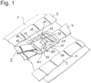
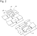
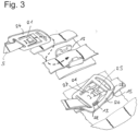
- FIG. 1 A first embodiment of a clasp according to the invention will now be described with reference to Figures 1 to 7 described.
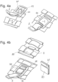
- Figures 1 to 4 show the function of the clasp, Figures 5 to 7 Details of the structure.
- the clasp according to the invention serves to attach a functional element to a belt loop 3 of an object 1 worn on the body, for example, a protective vest.
- the functional element (not shown) is attached via a belt element 5, which is attached to the belt loop 3 by means of the clasp.
- the clasp consists of a base element 10, which as in Fig. 2 shown can be pushed under the belt loop 3, and a connecting element 20 which can be connected to the base element 10.
- the basic element includes as in Fig. 2 and 6 visible a base region 14 and two web elements 11 which, when connected to the belt loop 3, extend on both sides of the belt loop in the longitudinal direction of the belt loop, so that the base element encompasses the belt loop on both sides, while the base region 14 connects the web elements 11 transversely to the direction of extension of the belt loop 3 through the belt loop 3.
- the bottom region 14 of the base element is formed by two webs 14 extending transversely to the direction of extension of the belt loop 3, between which a recess is provided. This saves material and weight and facilitates production, since the injection mold needs to be less complex.
- the connecting element 20 is connected to the web elements 11 which laterally surround the belt loop 3 in order to close the clasp and is secured to it by a latch.
- the connecting element 20 has a spring arm 21, which, as shown in Fig. 3 shown for fastening with the base element under holding elements 12, which project laterally from the web elements 11, pushed and in the in Fig. 1 shown inserted position.
- a locking pawl 23 is provided on the spring arm, which engages with counter elements 13 of the web elements 11.
- the counter elements 13 are formed by the end regions of the retaining elements 12, under which the spring arm is pushed.
- the locking pawl locks from below with the lower front edge of the respective retaining element 12.
- the spring arm 21 has a bevel at its free end, the bevelled end of which forms the pawl 23.
- the spring arm 21 is therefore The run-up slope is pushed under the holding elements 12. Once the run-up slope has completely passed the holding elements 12, the connecting element 20 is in the locked position, in which the locking pawl locks with the ends of the holding elements 12 acting as a counter element.
- the two retaining elements are each arranged on the inside of the respective web element 11, with the spring arm 21 being pushed between the two web elements under the retaining elements 12. In the retracted position, the spring arm 21 therefore rests on the belt loop 3, which in turn rests on the base area 14.
- a web of the base region is provided in the area of the free end of the spring arm 21.
- the free end of the spring arm 21 rests on the belt loop in the locked position, where it is supported by the web of the base region.
- the base region 14 has a recess 16, which simplifies production.
- the locking mechanism is released by pressing the spring arm 21 into the clasp onto the belt loop, which, due to its elasticity, gives way sufficiently to release the pawl.
- the spring arm 21 has a recess 25 and bead elements 26, which facilitate operation while wearing gloves.
- the recess 25 is located in the area between the two retaining elements 12 when the clasp is closed.
- the connecting element 20 has one or more connecting regions 22 for connection to a belt element 5.
- the connecting regions 22 are formed by recesses through which a belt loop passes. The edges of the connecting element 20 therefore form webs 29 around which the belt loop 5 is placed. The recesses 22 are closed.
- connecting areas 22 are provided in the longitudinal direction of the belt loop 3 on opposite sides of the connecting element 20.
- the connection to the belt element 5 is therefore made in the longitudinal direction of the belt loop 3.
- connecting regions can be provided on any side of the connecting element.
- the number of connecting regions is also arbitrary, and only one connecting region can also be provided.
- connection of the belt element 5 is therefore made transversely to the longitudinal direction of the belt loop 3.
- the connecting area is formed by a recess 22' and a web 29'.
- connecting areas 22 are provided on all four sides of the connecting element 20, the connection of the material element 5 can therefore take place in the longitudinal direction and transversely to the longitudinal direction of the belt loop 3.
- the connecting element is plate-shaped.
- the connecting element has a locking pawl on each of its main sides, so that it can be connected to the base element regardless of its orientation.
- both main sides are identically designed and/or the connecting element has a symmetrical design with respect to its central plane.
- the connecting element 20 has a support element 24 which, in the connected state, encompasses the web elements 11.
- the support element 24 in the exemplary embodiment has edges 28 extending transversely to the extension of the web elements 11, which encompass the end regions 15 of the web elements 11.
- the support element encompasses the web elements 11 on both longitudinal sides.
- the support element 24 extends parallel to the spring arm 21 in the longitudinal direction of the connecting element and connects the edges 28, which encompass the two end regions 15 of the web elements 11, in the longitudinal direction.
- the support element 24 connects in particular at least one connecting region 22 to the longitudinally opposite edges 28, with which the connecting element is supported on the end regions 15 of the web elements 11 in the event of a tensile load in the longitudinal direction and thereby secures the connecting element to the base element.
- the end regions 15 of the web elements 11 extend diagonally inwards from their upper edge to the base region 14.
- the edges 28 of the supporting element are braced, as can be seen from the corresponding side view in Fig. 7 visible under a tensile load with the end areas 15 and cannot slip off from these, since under tensile load the connecting element is pressed by the bevels 15 in the direction of the base area 14 onto the goods loop located between the base area 14 and the connecting element 20.
- the longitudinally parallel regions of the support element 24 and the spring arm 21 are separated by a recess 27, so that the two regions can be deformed independently of each other.
- the spring arm 21 can be deformed as shown in Fig. 3 shown are bent downwards from the plane of the connecting element in order to be pushed under the holding elements 12, while the supporting element is bent upwards in order to push the edges 28 over the web elements 11.
- the edges 28 slide along the upper edges of the web elements 11 until they engage around the web elements in their end regions 15.
- the support element 24 is thinner in the region in which it extends parallel to the spring arm 21 than in its end regions, in which the connecting regions 22 are provided. This increases the flexibility in this region.
- the support element 24 has two arms in the region in which it runs parallel to the spring arm, each of which extends on the outside of the web elements 11.
- the support element therefore surrounds the web elements in a frame-like manner when connected.
- the spring arm on the other hand, extends between the two web elements 11. Therefore, when connected, the web elements 11 pass through the recess 27 between the spring arm 21 and the arms of the support element 24.
- the edges 28 are formed by the longitudinal ends of this recess 27.
- the arm of the support element 24 opposite the connection area used for the tensile load is supported on the outer side of the associated web element 11. Similar to the end areas 15, the side walls of the web elements 21 can have an inwardly directed slope towards the base area in order to prevent accidental release under tensile load.
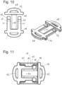
- FIG. 10 and 11 The alternative embodiment of the connecting element shown has the same design and functionality as the one shown in Fig. 1 to 7 described embodiment, so that reference is first made to the description there.
- the support element 44 runs differently than in the other embodiments in the area between the web elements 11.
- two spring arms 41 are provided, which extend on both sides of the centrally extending support element 44, wherein both the spring arms and the support element 44 extend between the web elements 11.
- the area of the support element 44, in which it extends parallel to the spring arms 41, is separated from the spring arms by slot-shaped recesses 47.
- This design also allows the spring arms 41 and support element 44 to be bent in opposite directions in order to slide the spring arms under the retaining elements 12 of the web elements 11.
- the area of the support element 44, in which it extends parallel to the spring arms 41, is thinner than the end regions of the support element and the spring arms 41.
- edges 48 of the support element, with which it engages the web elements 11 in their end regions 15, are formed by projections of the support element that project outward from the two end regions of the support element.
- the function of these edges 48 corresponds to that of the edges 28 of the first embodiment. In particular, when the clasp is closed, they slide on the upper side of the web elements 11 and engage the end regions 15 in the closed position.
- Connecting areas 42 formed by recesses are provided in the end regions.
- the closed recesses 42 create a web 49 around which a belt loop can be placed.
- connecting areas 42 are provided on both long sides of the connecting element.
- the present invention provides an easy-to-use, stable connection of the connecting element to the base element, through the interaction of which functional elements can be attached to a belt loop.
- connection element can be Fig. 4a shown can also be attached directly to the belt loop 3 by pushing the spring arm 21 behind the belt loop 3 and then through the recesses 27 between the spring arm 21 and supporting element 24.
- Such a connection would also be possible in the embodiment in Figs. 10 and 11 This is possible by pushing the two spring arms behind the belt loop, which then runs through the recesses 47. This allows a connection in the transverse direction of the loop.
- a reinforcing element 50 can be used, which reinforces the belt loop 3 so that it cannot give way when the buckle is loaded.
- the reinforcement element 50 surrounds the belt loop 3 in the assembled state in a sleeve-like manner. It has dimensions that allow the support element 24 to surround the reinforcement element 50 in the assembled state in a frame-like manner.
- the area of the belt loop 3 under which the spring arm 21 has been pushed is stabilized by the reinforcement element 50. Furthermore, the reinforcement element rests on the spring arm 21 in the assembled state, so that when the connecting element is loaded in or against the assembly direction, the edges 28 interlock with the reinforcement element 50.
- the reinforcing element 50 has a longitudinal slot 51 by means of which it can be pushed onto the belt loop.
- the edges of the slot 51 together with the locking pawl 23 of the spring arm 21 ensure that the securing function is maintained by interlocking during disassembly.
- the belt loop 3 can in particular be a PALS loop of a MOLLE fastening system.
- the belt loop 3 can be provided, for example, by sewing a belt strap 2 onto a carrier layer 1.
- a belt strap can be connected to the carrier layer 1 at regular intervals via darts 4 in order to provide several belt loops along the belt strap 2.
- the belt loops can also be provided by slits in a layer of material through which belt straps can be threaded in the same way as in a design with the sewn-on belt straps described above.
- the clasp can also be used to connect any other loops.
Landscapes
- Engineering & Computer Science (AREA)
- Textile Engineering (AREA)
- General Engineering & Computer Science (AREA)
- Health & Medical Sciences (AREA)
- General Health & Medical Sciences (AREA)
- Physical Education & Sports Medicine (AREA)
- Buckles (AREA)
- Clamps And Clips (AREA)
Priority Applications (2)
| Application Number | Priority Date | Filing Date | Title |
|---|---|---|---|
| RS20250720A RS67036B1 (sr) | 2022-02-22 | 2023-01-10 | Kopča |
| HRP20250834TT HRP20250834T1 (hr) | 2022-02-22 | 2023-01-10 | Kopča |
Applications Claiming Priority (1)
| Application Number | Priority Date | Filing Date | Title |
|---|---|---|---|
| DE102022104175.1A DE102022104175A1 (de) | 2022-02-22 | 2022-02-22 | Schließe |
Publications (3)
| Publication Number | Publication Date |
|---|---|
| EP4230079A1 EP4230079A1 (de) | 2023-08-23 |
| EP4230079B1 true EP4230079B1 (de) | 2025-06-18 |
| EP4230079C0 EP4230079C0 (de) | 2025-06-18 |
Family
ID=84901730
Family Applications (1)
| Application Number | Title | Priority Date | Filing Date |
|---|---|---|---|
| EP23150854.0A Active EP4230079B1 (de) | 2022-02-22 | 2023-01-10 | Schliesse |
Country Status (9)
| Country | Link |
|---|---|
| US (1) | US12274332B2 (pl) |
| EP (1) | EP4230079B1 (pl) |
| CA (1) | CA3190133A1 (pl) |
| DE (1) | DE102022104175A1 (pl) |
| ES (1) | ES3041059T3 (pl) |
| HR (1) | HRP20250834T1 (pl) |
| HU (1) | HUE072896T2 (pl) |
| PL (1) | PL4230079T3 (pl) |
| RS (1) | RS67036B1 (pl) |
Families Citing this family (2)
| Publication number | Priority date | Publication date | Assignee | Title |
|---|---|---|---|---|
| US12369669B2 (en) * | 2022-08-29 | 2025-07-29 | Msa Technology, Llc | Systems and methods for providing reliable helmet suspension installation |
| US20250288029A1 (en) * | 2024-03-15 | 2025-09-18 | Donald Paul Meeker | Modular utility latching system |
Family Cites Families (15)
| Publication number | Priority date | Publication date | Assignee | Title |
|---|---|---|---|---|
| KR100572526B1 (ko) | 1998-12-18 | 2006-04-24 | 내셔날 몰딩 코오포레이션 | 다목적 부착 기구 |
| TW200806217A (en) * | 2006-05-08 | 2008-02-01 | Korea Ind Fastener Corp | Release buckle |
| US7950554B2 (en) | 2006-09-08 | 2011-05-31 | Brian D. Hoffner | Harness for firearm accessories |
| WO2009048584A1 (en) | 2007-10-09 | 2009-04-16 | Gregory Thomas M | Rotatable accessory attachment platform |
| US20120175391A1 (en) | 2007-12-17 | 2012-07-12 | Prezine, Llc | Multi-mount system for removably securing articles to garments |
| US20110061211A1 (en) | 2009-09-17 | 2011-03-17 | Joseph Anscher | Removable buckle |
| WO2013096110A1 (en) | 2011-12-19 | 2013-06-27 | Illinois Tool Works Inc. | Webbing mounting assembly |
| US9487376B2 (en) | 2012-01-16 | 2016-11-08 | Hammerhead Industries, Inc. | Retracting device for mounting to a web strap |
| WO2013184594A1 (en) * | 2012-06-06 | 2013-12-12 | Illinois Tool Works Inc. | Multi-directional buckle assembly |
| US8925156B2 (en) * | 2012-09-14 | 2015-01-06 | Cerena West Zutis | Attachable fastener shield |
| US10281240B2 (en) * | 2013-01-14 | 2019-05-07 | FirstSpear, LLC | Modular armor supplement apparatus and system with silent fasteners and adjustability |
| CA2953176A1 (en) | 2016-12-28 | 2018-06-28 | Productions Wedoodle Inc. | Swivel clip |
| US10918169B2 (en) * | 2018-03-02 | 2021-02-16 | Illinois Tool Works Inc. | Locking position adjustment device |
| US11044970B1 (en) * | 2020-03-30 | 2021-06-29 | Duraflex Hong Kong Limited | Attachment system with quick release |
| US11564459B2 (en) * | 2021-03-30 | 2023-01-31 | Central Lake Armor Express, Inc. | Buckle assembly |
-
2022
- 2022-02-22 DE DE102022104175.1A patent/DE102022104175A1/de active Pending
-
2023
- 2023-01-10 EP EP23150854.0A patent/EP4230079B1/de active Active
- 2023-01-10 PL PL23150854.0T patent/PL4230079T3/pl unknown
- 2023-01-10 HR HRP20250834TT patent/HRP20250834T1/hr unknown
- 2023-01-10 ES ES23150854T patent/ES3041059T3/es active Active
- 2023-01-10 HU HUE23150854A patent/HUE072896T2/hu unknown
- 2023-01-10 RS RS20250720A patent/RS67036B1/sr unknown
- 2023-02-06 US US18/165,261 patent/US12274332B2/en active Active
- 2023-02-16 CA CA3190133A patent/CA3190133A1/en active Pending
Also Published As
| Publication number | Publication date |
|---|---|
| HRP20250834T1 (hr) | 2025-09-12 |
| PL4230079T3 (pl) | 2025-11-03 |
| ES3041059T3 (en) | 2025-11-06 |
| EP4230079A1 (de) | 2023-08-23 |
| EP4230079C0 (de) | 2025-06-18 |
| US12274332B2 (en) | 2025-04-15 |
| DE102022104175A1 (de) | 2023-08-24 |
| CA3190133A1 (en) | 2023-08-22 |
| HUE072896T2 (hu) | 2025-12-28 |
| US20230263272A1 (en) | 2023-08-24 |
| RS67036B1 (sr) | 2025-08-29 |
Similar Documents
| Publication | Publication Date | Title |
|---|---|---|
| EP3638069B1 (de) | Verschlussvorrichtung zum lösbaren verbinden zweier teile | |
| DE19801278C2 (de) | Gegossenes Eingriffsteil für einen Flächenhaftverschluß | |
| DE19754121B4 (de) | Mehrzweckclip | |
| EP4230079B1 (de) | Schliesse | |
| DE3109792A1 (de) | Schliesse oder schnalle, insbesondere fuer uhrarmbaender | |
| DE2653036C3 (de) | Vorgefertigte ReiDverschlußeinheit | |
| DE1610445B2 (de) | Druckknopfverschluß aus Kunststoff | |
| EP3490844B1 (de) | Flächiges sicherungsmittel | |
| EP0389831B1 (de) | Vorrichtung zum Binden langgestreckter Gegenstände | |
| WO2018055033A1 (de) | Verschlussvorrichtung zum verbinden zweier teile | |
| EP3694368B1 (de) | Haftverschlusssystem | |
| DE4107912B4 (de) | Tragekorb | |
| DE9211744U1 (de) | Rucksack | |
| EP0922895B1 (de) | Vorrichtung zum Binden eines langgestreckten Gegenstands | |
| DE3803026C2 (pl) | ||
| EP4190205B1 (de) | Komponente eines tragsystems | |
| CH648813A5 (en) | Device for connecting formwork panels stacked one on top of the other | |
| DE102022211736B4 (de) | Vorrichtung zur Stabilisierung eines Einführbereiches für einen Gurt und Fahrzeug mit mindestens einer solchen | |
| EP0439053B1 (de) | Verschluss zum Einstellen von Gurtbändern | |
| DE102019123573A1 (de) | Transportsicherung | |
| DE2551978A1 (de) | Stuhl, bestehend aus starrem unterrahmen und einer darauf loesbar befestigten sitzschale | |
| DE3135955C2 (de) | Teilbarer Reißverschluß | |
| DE202025000359U1 (de) | Schlaufenband für variabel an Bekleidungsgegenständen und/oder Ausrüstungsgegenständen anzuordnende Gegenstände, wie Taschen, Kabel oder Schläuche | |
| DE8628812U1 (de) | Befestigungsteil für Taschen o.dgl. an Traggurten | |
| DE19843633C2 (de) | Vorrichtung aus Kunststoff zum Haltern von Rohren, Kabeln oder rohrförmigen Gegenständen |
Legal Events
| Date | Code | Title | Description |
|---|---|---|---|
| REG | Reference to a national code |
Ref country code: HR Ref legal event code: TUEP Ref document number: P20250834T Country of ref document: HR |
|
| PUAI | Public reference made under article 153(3) epc to a published international application that has entered the european phase |
Free format text: ORIGINAL CODE: 0009012 |
|
| STAA | Information on the status of an ep patent application or granted ep patent |
Free format text: STATUS: THE APPLICATION HAS BEEN PUBLISHED |
|
| AK | Designated contracting states |
Kind code of ref document: A1 Designated state(s): AL AT BE BG CH CY CZ DE DK EE ES FI FR GB GR HR HU IE IS IT LI LT LU LV MC ME MK MT NL NO PL PT RO RS SE SI SK SM TR |
|
| STAA | Information on the status of an ep patent application or granted ep patent |
Free format text: STATUS: REQUEST FOR EXAMINATION WAS MADE |
|
| 17P | Request for examination filed |
Effective date: 20240223 |
|
| RBV | Designated contracting states (corrected) |
Designated state(s): AL AT BE BG CH CY CZ DE DK EE ES FI FR GB GR HR HU IE IS IT LI LT LU LV MC ME MK MT NL NO PL PT RO RS SE SI SK SM TR |
|
| GRAP | Despatch of communication of intention to grant a patent |
Free format text: ORIGINAL CODE: EPIDOSNIGR1 |
|
| STAA | Information on the status of an ep patent application or granted ep patent |
Free format text: STATUS: GRANT OF PATENT IS INTENDED |
|
| RIC1 | Information provided on ipc code assigned before grant |
Ipc: F41C 33/04 20060101ALN20250123BHEP Ipc: A45F 5/02 20060101ALI20250123BHEP Ipc: F41H 5/013 20060101ALI20250123BHEP Ipc: A41D 13/05 20060101ALI20250123BHEP Ipc: A41F 1/00 20060101ALI20250123BHEP Ipc: A44B 11/25 20060101AFI20250123BHEP |
|
| RIC1 | Information provided on ipc code assigned before grant |
Ipc: F41C 33/04 20060101ALN20250128BHEP Ipc: A45F 5/02 20060101ALI20250128BHEP Ipc: F41H 5/013 20060101ALI20250128BHEP Ipc: A41D 13/05 20060101ALI20250128BHEP Ipc: A41F 1/00 20060101ALI20250128BHEP Ipc: A44B 11/25 20060101AFI20250128BHEP |
|
| INTG | Intention to grant announced |
Effective date: 20250213 |
|
| GRAS | Grant fee paid |
Free format text: ORIGINAL CODE: EPIDOSNIGR3 |
|
| GRAA | (expected) grant |
Free format text: ORIGINAL CODE: 0009210 |
|
| STAA | Information on the status of an ep patent application or granted ep patent |
Free format text: STATUS: THE PATENT HAS BEEN GRANTED |
|
| AK | Designated contracting states |
Kind code of ref document: B1 Designated state(s): AL AT BE BG CH CY CZ DE DK EE ES FI FR GB GR HR HU IE IS IT LI LT LU LV MC ME MK MT NL NO PL PT RO RS SE SI SK SM TR |
|
| REG | Reference to a national code |
Ref country code: GB Ref legal event code: FG4D Free format text: NOT ENGLISH |
|
| REG | Reference to a national code |
Ref country code: CH Ref legal event code: EP |
|
| REG | Reference to a national code |
Ref country code: DE Ref legal event code: R096 Ref document number: 502023001153 Country of ref document: DE |
|
| REG | Reference to a national code |
Ref country code: CH Ref legal event code: EP |
|
| REG | Reference to a national code |
Ref country code: IE Ref legal event code: FG4D Free format text: LANGUAGE OF EP DOCUMENT: GERMAN |
|
| U01 | Request for unitary effect filed |
Effective date: 20250618 |
|
| U07 | Unitary effect registered |
Designated state(s): AT BE BG DE DK EE FI FR IT LT LU LV MT NL PT RO SE SI Effective date: 20250626 |
|
| REG | Reference to a national code |
Ref country code: SK Ref legal event code: T3 Ref document number: E 46673 Country of ref document: SK |
|
| REG | Reference to a national code |
Ref country code: HR Ref legal event code: T1PR Ref document number: P20250834 Country of ref document: HR |
|
| REG | Reference to a national code |
Ref country code: GR Ref legal event code: EP Ref document number: 20250401856 Country of ref document: GR Effective date: 20251009 |
|
| REG | Reference to a national code |
Ref country code: ES Ref legal event code: FG2A Ref document number: 3041059 Country of ref document: ES Kind code of ref document: T3 Effective date: 20251106 |
|
| U1N | Appointed representative for the unitary patent procedure changed after the registration of the unitary effect |
Representative=s name: LORENZ SEIDLER GOSSEL PART. MBB; DE |
|
| REG | Reference to a national code |
Ref country code: HU Ref legal event code: AG4A Ref document number: E072896 Country of ref document: HU |
|
| PG25 | Lapsed in a contracting state [announced via postgrant information from national office to epo] |
Ref country code: SM Free format text: LAPSE BECAUSE OF FAILURE TO SUBMIT A TRANSLATION OF THE DESCRIPTION OR TO PAY THE FEE WITHIN THE PRESCRIBED TIME-LIMIT Effective date: 20250618 |
|
| PGFP | Annual fee paid to national office [announced via postgrant information from national office to epo] |
Ref country code: MK Payment date: 20251218 Year of fee payment: 4 |
|
| PGFP | Annual fee paid to national office [announced via postgrant information from national office to epo] |
Ref country code: HR Payment date: 20251218 Year of fee payment: 4 |
|
| PGFP | Annual fee paid to national office [announced via postgrant information from national office to epo] |
Ref country code: AL Payment date: 20251219 Year of fee payment: 4 |
|
| REG | Reference to a national code |
Ref country code: HR Ref legal event code: ODRP Ref document number: P20250834 Country of ref document: HR Payment date: 20251218 Year of fee payment: 4 |
|
| PGFP | Annual fee paid to national office [announced via postgrant information from national office to epo] |
Ref country code: ME Payment date: 20251217 Year of fee payment: 4 |
|
| PGFP | Annual fee paid to national office [announced via postgrant information from national office to epo] |
Ref country code: CZ Payment date: 20251218 Year of fee payment: 4 |
|
| PGFP | Annual fee paid to national office [announced via postgrant information from national office to epo] |
Ref country code: PL Payment date: 20251219 Year of fee payment: 4 |
|
| PGFP | Annual fee paid to national office [announced via postgrant information from national office to epo] |
Ref country code: SK Payment date: 20251219 Year of fee payment: 4 |
|
| PGFP | Annual fee paid to national office [announced via postgrant information from national office to epo] |
Ref country code: RS Payment date: 20251218 Year of fee payment: 4 |
|
| REG | Reference to a national code |
Ref country code: CH Ref legal event code: U11 Free format text: ST27 STATUS EVENT CODE: U-0-0-U10-U11 (AS PROVIDED BY THE NATIONAL OFFICE) Effective date: 20260201 |
|
| PGFP | Annual fee paid to national office [announced via postgrant information from national office to epo] |
Ref country code: HU Payment date: 20251223 Year of fee payment: 4 |
|
| U20 | Renewal fee for the european patent with unitary effect paid |
Year of fee payment: 4 Effective date: 20260128 |
|
| PGFP | Annual fee paid to national office [announced via postgrant information from national office to epo] |
Ref country code: ES Payment date: 20260202 Year of fee payment: 4 |
|
| PGFP | Annual fee paid to national office [announced via postgrant information from national office to epo] |
Ref country code: NO Payment date: 20260127 Year of fee payment: 4 Ref country code: IE Payment date: 20260116 Year of fee payment: 4 |
|
| PGFP | Annual fee paid to national office [announced via postgrant information from national office to epo] |
Ref country code: IS Payment date: 20260107 Year of fee payment: 4 |
|
| PGFP | Annual fee paid to national office [announced via postgrant information from national office to epo] |
Ref country code: TR Payment date: 20260102 Year of fee payment: 4 |
|
| PLBE | No opposition filed within time limit |
Free format text: ORIGINAL CODE: 0009261 |
|
| STAA | Information on the status of an ep patent application or granted ep patent |
Free format text: STATUS: NO OPPOSITION FILED WITHIN TIME LIMIT |