EP4230094A1 - Décanteur grande bouteille - Google Patents
Décanteur grande bouteille Download PDFInfo
- Publication number
- EP4230094A1 EP4230094A1 EP22157878.4A EP22157878A EP4230094A1 EP 4230094 A1 EP4230094 A1 EP 4230094A1 EP 22157878 A EP22157878 A EP 22157878A EP 4230094 A1 EP4230094 A1 EP 4230094A1
- Authority
- EP
- European Patent Office
- Prior art keywords
- carriage
- bottle
- spring
- decanter
- der
- Prior art date
- Legal status (The legal status is an assumption and is not a legal conclusion. Google has not performed a legal analysis and makes no representation as to the accuracy of the status listed.)
- Withdrawn
Links
- 235000013361 beverage Nutrition 0.000 claims abstract description 12
- 238000000034 method Methods 0.000 claims abstract description 12
- 239000007788 liquid Substances 0.000 claims description 17
- 230000006835 compression Effects 0.000 claims description 11
- 238000007906 compression Methods 0.000 claims description 11
- 230000005484 gravity Effects 0.000 claims description 10
- 229920001971 elastomer Polymers 0.000 claims description 3
- 230000002441 reversible effect Effects 0.000 claims description 3
- RRHGJUQNOFWUDK-UHFFFAOYSA-N Isoprene Chemical compound CC(=C)C=C RRHGJUQNOFWUDK-UHFFFAOYSA-N 0.000 claims description 2
- 239000007799 cork Substances 0.000 claims description 2
- 229920001195 polyisoprene Polymers 0.000 claims description 2
- 229920001296 polysiloxane Polymers 0.000 claims description 2
- 210000002023 somite Anatomy 0.000 description 23
- 210000001015 abdomen Anatomy 0.000 description 3
- 229920001817 Agar Polymers 0.000 description 2
- 206010053648 Vascular occlusion Diseases 0.000 description 2
- 239000011521 glass Substances 0.000 description 1
- 239000013049 sediment Substances 0.000 description 1
- 239000004447 silicone coating Substances 0.000 description 1
Images

Classifications
-
- A—HUMAN NECESSITIES
- A47—FURNITURE; DOMESTIC ARTICLES OR APPLIANCES; COFFEE MILLS; SPICE MILLS; SUCTION CLEANERS IN GENERAL
- A47G—HOUSEHOLD OR TABLE EQUIPMENT
- A47G23/00—Other table equipment
- A47G23/02—Glass or bottle holders
- A47G23/0241—Glass or bottle holders for bottles; Decanters
-
- B—PERFORMING OPERATIONS; TRANSPORTING
- B67—OPENING, CLOSING OR CLEANING BOTTLES, JARS OR SIMILAR CONTAINERS; LIQUID HANDLING
- B67D—DISPENSING, DELIVERING OR TRANSFERRING LIQUIDS, NOT OTHERWISE PROVIDED FOR
- B67D3/00—Apparatus or devices for controlling flow of liquids under gravity from storage containers for dispensing purposes
- B67D3/0051—Apparatus or devices for controlling flow of liquids under gravity from storage containers for dispensing purposes dispensing by tilting
-
- B—PERFORMING OPERATIONS; TRANSPORTING
- B67—OPENING, CLOSING OR CLEANING BOTTLES, JARS OR SIMILAR CONTAINERS; LIQUID HANDLING
- B67D—DISPENSING, DELIVERING OR TRANSFERRING LIQUIDS, NOT OTHERWISE PROVIDED FOR
- B67D3/00—Apparatus or devices for controlling flow of liquids under gravity from storage containers for dispensing purposes
- B67D3/0054—Mounting or arrangements of dispensing apparatus in shops or bar counters
-
- B—PERFORMING OPERATIONS; TRANSPORTING
- B67—OPENING, CLOSING OR CLEANING BOTTLES, JARS OR SIMILAR CONTAINERS; LIQUID HANDLING
- B67D—DISPENSING, DELIVERING OR TRANSFERRING LIQUIDS, NOT OTHERWISE PROVIDED FOR
- B67D3/00—Apparatus or devices for controlling flow of liquids under gravity from storage containers for dispensing purposes
- B67D3/0058—Details
- B67D3/008—Supports
- B67D3/0083—Supports for the liquid container
Definitions
- the present invention relates to a large-bottle decanter, a method for pouring beverages from large bottles without turbulence using the large-bottle decanter, and to the use of the large-bottle decanter.
- Beverages in large bottles i.e. bottles with a capacity of at least 1.5 liters, are often difficult to serve by hand and without a dispensing aid due to their weight.
- turbulence occurs in the bottle when the beverage is poured out and when the bottle is brought back into a vertical position, for example.
- these are often undesirable, for example in wine bottles.
- the decanters are fitted with a motor that controls the tilting of the bottles.
- the motor increases the weight of the decanter, making it more difficult to transport the decanter.
- the motor requires either a power connection or a battery resp. a battery.
- a power cable is often a nuisance and poses a risk of accidents.
- the battery must be replaced periodically and the battery charged regularly. If this is done too late, there is a risk that the motor will suddenly stop while the drink is being dispensed and the bottle will not be able to be moved vertically again, or only with difficulty.
- the decanters are equipped without a motor and are operated manually.
- the decanters include a carriage on which the bottles are attached.
- the carriage is connected to the decanter base via at least two rigid elements, whereby one element is changed by actuating a gearwheel or thread in such a way that the angle - and thus also the bottle lying on the carriage - of the carriage to the horizontal increases. to pour the wine.
- decanters are often very complex in design. As a result, their weight is not negligible, which means that the decanters can only be moved with great effort. Another disadvantage of the known decanters is that there is a risk that too much drink will be poured out, since the slide is reset too slowly—due to the many crank movements.
- the object of the present invention to provide a manually operated decanter without a motor for large bottles, which is not too heavy and is therefore easy to transport.
- the decanter should be able to be quickly returned to the starting position in order to prevent the filled containers from being overfilled.
- the use of the large bottle decanter (1) according to the invention is also claimed for holding large bottles (2), the bottles (2) preferably having a volume of at least 1.5 liters, in particular of at least 3 litres, and/or are wine bottles.
- the decanter (1) is extremely easy to use and the decanting of liquids, i.e. serving drinks such as wine, can be dosed very precisely. As a result, the liquid is only moved very slightly both when it is served and when the bottle (2) is tilted back, which means that no turbulence occurs. This means that any sediment in the bottle (2) is not stirred up, which is very important when decanting the liquid.
- the carriage (5) has a natural resilience, i.e. that the carriage automatically tilts back towards the starting position after dispensing due to the spring force, which prevents too much liquid from being dispensed.
- the decanter (1) also has a low weight, in particular in comparison to known decanters, and can therefore be transported easily. Fewer individual parts are also required to produce the decanter (1), which means that it can be produced more simply and cost-effectively. This in turn is a clear advantage in marketing the decanter (1). Since it is operated without a motor, the decanter (1) does not require a power connection and no batteries need to be replaced or a rechargeable battery charged.
- the large-bottle decanter (1) according to the invention is particularly suitable for dispensing beverages from large bottles (2) without turbulence, ie bottles with a filling volume of at least 1.5 liters, in particular at least 3 liters.
- the decanter (1) is also suitable for bottles with a filling volume of 18 liters, for example, with the bottles in many cases are wine bottles.
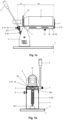
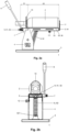
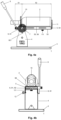
- the carriage (5) of the decanter (1) is dimensioned in such a way that the bottle belly of the bottle (2) can rest on the carriage (5) and at least the uppermost part of the bottle neck with the bottle opening of the bottle (2) over the carriage ( 5) protrudes.
- the decanter (1) according to the invention does not include a motor.
- the axis (7) is arranged at right angles to the longitudinal sides of the carriage (5), the axis (7) dividing the carriage (5) into a shorter bottle spout part (51) and a longer bottle bottom - part (52), the length of the bottle spout part (51) and the length of the bottle bottom part (52) being measured in the longitudinal direction of the carriage (5) and thus together corresponding to the length of the carriage (5).
- the center of gravity of the carriage (5) is in the area of the bottle bottom part (52). If a filled bottle (2) is now placed on the carriage (5) so that the bottle belly rests on the bottle base part (52) of the carriage (5), the center of gravity of the carriage (5) with the bottle (2) moves away from the axis (7). In addition, the force exerted on the spring (8) increases. The consequence of this is that the bottle base part (52) of the carriage (5) automatically inclines towards the base (3) and the bottle spout part (51) upwards. This prevents drink from flowing out, even from a full bottle (2).
- the spring force of the spring (8, 81, 82) and the length of the spring (82) are preferably selected so that the carriage (5) without the bottle (2) at rest has an inclination to the horizontal of up to 50°, preferably up to to 30°, in particular up to 15°, with the bottle base part (52) typically being lower than the bottle spout part (51). If a full bottle (2) is now placed on the carriage (5), the inclination of the carriage (5) to the horizontal is preferably up to 60°, preferably up to 45° and in particular up to 30°.
- the expert can the spring force and the length of the spring (82) depending, inter alia, on the weight of the full bottle (2), the position of the carriage (5) respectively.
- a decanter (1) for smaller bottles for example 1.5 to 4.5 liters, can also have a different spring force and/or spring length than a decanter (1) for larger bottles, for example 5 to 18 liters.
- the carriage (5) of the decanter (1) preferably comprises a carriage base (53), two carriage sides (54) and optionally a support surface (55) for each carriage side (54) for receiving the bottles (2).
- the bearing surfaces (55) allow the bottles (2) to be picked up better, the latter also being able to be placed directly on the upper edges of the sides of the carriage (54).
- the length of the carriage (5) advantageously corresponds approximately to the length of the bottle belly in order to ensure that the bottle (2) is optimally accommodated.
- the carriage (5) comprises an adjustment unit (9) to which the axle (7) or the spring attachment (822) is attached, whereby the position of the axle (7) or the spring attachment (822) in the longitudinal direction of the carriage ( 5) can be reversibly changed.
- the adjustment unit (9) is preferably attached to the carriage base (53), in particular to the bottle spout part (51) of the carriage (5). This allows the point of application of the force of the spring (82) to be shifted and thus the inclination of the carriage (5) - and the bottle (2) - depending on the exact position of the bottle (7) on the carriage (5) and the bottle weight, and thus also depending on the filling volume of the bottle, optimally and reversibly shift, i.e. adjust.
- the adjustment unit (9) preferably comprises at least one elongate guide (91) with a thread and a rotary handle or crank attached thereto, collectively called the rotary handle (92), the guide (91) being on the axle (7) or on the spring attachment (822 )
- the spring (82) and the rotary handle (92) is preferably attached to the carriage (5), the position of the elongated Guide (91) - can be reversibly changed in relation to the axis (7) and / or the spring attachment (822) with the rotary handle (92) in the longitudinal direction of the carriage (5). This changes the ratio of the bottle spout part (51) to the bottle bottom part (52) and thus also the position of the center of gravity of the bottle on the carriage (5).
- the decanter (1) has a locking bolt (12) which reversibly connects the holder (4) to the carriage (5) in order to lock the carriage (5) at the desired inclination
- the locking bolt (12 ) is preferably attached to the holder (4) and the carriage (5) on the corresponding carriage side (54) and in the area of the axis (7), but spaced evenly from the axis (7), a plurality, in particular 3 to 9, has openings into which the locking bolt (12) can reversibly engage to lock the carriage.
- an open but not yet empty bottle can be fixed and stored on the carriage (5) - and thus on the decanter (1) - without it being swiveled by mistake, which can cause unwanted turbulence or - with the bottle open - Liquid can escape.
- the position of the axis (7) or the spring attachment (822) of the spring (82) in the longitudinal direction of the carriage (5) changed to change the center of gravity of the carriage (5) relative to the axle (7) or the spring tab (822).
- This allows an optimal inclination of the carriage (5) - and possibly the bottle (2) - in the rest position.
- the inclination - relative to the horizontal - can be set both for a new, filled bottle (2) and after part of the liquid has been poured out, whereby the bottle (2) requires a smaller angle of inclination for its rest position without liquid running out the bottle leaks.
- turbulence when serving and/or when returning the bottle to the idle position is additionally reduced or completely prevented. This applies in particular when the bottle (2) is only 50% or less full, for example, or in particular only 25% or less full.
- the bottom of the bottle (2) is fixed by means of bottle delimitation (11) and/or the bottle neck of the bottle (2) is fixed by means of fastening means (10). Due to the bottle limitation (11), the bottle (2) cannot slide backwards and the fastening means (10) allows the bottle (2) to be fixed laterally on the carriage (5) of the decanter (1).
- the inclination of the carriage (5) and thus of the bottle (2) is changed by actuating the rotary handle (92) of the adjustment unit (9) and, if necessary, fixed by means of locking bolts (12).
- the angle of inclination of the bottle (2) can be adapted to its size and/or filling volume, as a result of which a smaller inclination is required for turbulence-free dispensing, as a result of which no or at least less turbulence occurs in the bottle.
- the large bottle decanter (1) according to the invention is used according to the invention for holding large bottles (2), the bottles (2) preferably having a volume of at least 1.5 liters, in particular at least 3 liters, and/or being wine bottles.
- the beverages are dispensed from the bottles (2) preferably without turbulence.
Landscapes
- Engineering & Computer Science (AREA)
- Mechanical Engineering (AREA)
- Filling Of Jars Or Cans And Processes For Cleaning And Sealing Jars (AREA)
Priority Applications (1)
| Application Number | Priority Date | Filing Date | Title |
|---|---|---|---|
| EP22157878.4A EP4230094A1 (fr) | 2022-02-22 | 2022-02-22 | Décanteur grande bouteille |
Applications Claiming Priority (1)
| Application Number | Priority Date | Filing Date | Title |
|---|---|---|---|
| EP22157878.4A EP4230094A1 (fr) | 2022-02-22 | 2022-02-22 | Décanteur grande bouteille |
Publications (1)
| Publication Number | Publication Date |
|---|---|
| EP4230094A1 true EP4230094A1 (fr) | 2023-08-23 |
Family
ID=80446770
Family Applications (1)
| Application Number | Title | Priority Date | Filing Date |
|---|---|---|---|
| EP22157878.4A Withdrawn EP4230094A1 (fr) | 2022-02-22 | 2022-02-22 | Décanteur grande bouteille |
Country Status (1)
| Country | Link |
|---|---|
| EP (1) | EP4230094A1 (fr) |
Citations (7)
| Publication number | Priority date | Publication date | Assignee | Title |
|---|---|---|---|---|
| DE215235C (fr) * | ||||
| FR377009A (fr) * | 1907-04-20 | 1907-08-27 | Leon Brossier | Appareil pour la dégustation des vins fins |
| GB190911912A (en) * | 1909-05-20 | 1909-10-07 | Adolf Kunz | Improved Holder for use in Dispensing Liquids from Bottles. |
| GB402986A (en) * | 1933-04-04 | 1933-12-14 | Gustav Mayer | Device for decanting wine from bottles |
| GB2203719A (en) * | 1987-04-02 | 1988-10-26 | Anthony Ronald Laker | Tipping containers |
| DE29506886U1 (de) * | 1995-04-24 | 1995-06-29 | Mügschl, Eduard, Dipl.-Ing. Dr., 84533 Stammham | Dekantiergerät zum Dekantieren von Weinen und Flüssigkeiten |
| ITPI20110039A1 (it) * | 2011-04-08 | 2012-10-09 | Colombini Andrea | Supporto versatore per bottiglie. |
-
2022
- 2022-02-22 EP EP22157878.4A patent/EP4230094A1/fr not_active Withdrawn
Patent Citations (7)
| Publication number | Priority date | Publication date | Assignee | Title |
|---|---|---|---|---|
| DE215235C (fr) * | ||||
| FR377009A (fr) * | 1907-04-20 | 1907-08-27 | Leon Brossier | Appareil pour la dégustation des vins fins |
| GB190911912A (en) * | 1909-05-20 | 1909-10-07 | Adolf Kunz | Improved Holder for use in Dispensing Liquids from Bottles. |
| GB402986A (en) * | 1933-04-04 | 1933-12-14 | Gustav Mayer | Device for decanting wine from bottles |
| GB2203719A (en) * | 1987-04-02 | 1988-10-26 | Anthony Ronald Laker | Tipping containers |
| DE29506886U1 (de) * | 1995-04-24 | 1995-06-29 | Mügschl, Eduard, Dipl.-Ing. Dr., 84533 Stammham | Dekantiergerät zum Dekantieren von Weinen und Flüssigkeiten |
| ITPI20110039A1 (it) * | 2011-04-08 | 2012-10-09 | Colombini Andrea | Supporto versatore per bottiglie. |
Similar Documents
| Publication | Publication Date | Title |
|---|---|---|
| EP4230094A1 (fr) | Décanteur grande bouteille | |
| DE3311844C2 (fr) | ||
| DE1455534A1 (de) | Kippfahrzeug fuer grosse Behaelter | |
| DE509883C (de) | Anordnung an Fluessigkeitsabzapfvorrichtungen | |
| DE231830C (fr) | ||
| DE92231C (fr) | ||
| DE1482667C3 (de) | Vorrichtung zum gleichzeitigen Füllen mehrerer Flaschen oder ähnlicher Gefäße | |
| AT522047B1 (de) | Schwimmvorrichtung für ein Gefäss | |
| DE179109C (fr) | ||
| DE84884C (fr) | ||
| EP2580146B1 (fr) | Dispositif pour recevoir des récipients de maniere pivotable | |
| DE19951628B4 (de) | Beladerohr Staukopf | |
| DE898C (de) | Kontroiapparat für Branntweinbrennereien | |
| DE449124C (de) | Selbsttaetige Waage mit Krafteinschaltung | |
| DE529025C (de) | Gefaessfoerderanlage | |
| DE125973C (fr) | ||
| DE202004008456U1 (de) | Behälter für ein Getränk | |
| DE678283C (de) | Ausgiessvorrichtung fuer Fluessigkeitsbehaelter | |
| DE62354C (de) | Eine Vorrichtung zum Ein- und Abfüllen von Bier, sowie zum Durchlüften des Bieres | |
| DE110149C (fr) | ||
| AT409958B (de) | Abgabebehälter für getränke | |
| DE748664C (de) | Kippvorrichtung zum Entleeren von zum Giessen von Stereotypplatten dienenden Schmelzkesseln | |
| DE338498C (de) | Vorrichtung zum Entleeren von Korbflaschen und aehnlichen Gefaessen, die durch Drehen eines Traggestelles in die Kipplage gebracht werden | |
| DE180615C (fr) | ||
| DE102009059340B4 (de) | Vorrichtung zur Aufnahme eines Schlauches, insbesondere eines Schlauches aus einem Bag-in-Box-System |
Legal Events
| Date | Code | Title | Description |
|---|---|---|---|
| PUAI | Public reference made under article 153(3) epc to a published international application that has entered the european phase |
Free format text: ORIGINAL CODE: 0009012 |
|
| STAA | Information on the status of an ep patent application or granted ep patent |
Free format text: STATUS: THE APPLICATION HAS BEEN PUBLISHED |
|
| AK | Designated contracting states |
Kind code of ref document: A1 Designated state(s): AL AT BE BG CH CY CZ DE DK EE ES FI FR GB GR HR HU IE IS IT LI LT LU LV MC MK MT NL NO PL PT RO RS SE SI SK SM TR |
|
| 18D | Application deemed to be withdrawn |
Effective date: 20240224 |