EP4230236A1 - Tube de séparation de sang comprenant une partie d'activation de cellule - Google Patents
Tube de séparation de sang comprenant une partie d'activation de cellule Download PDFInfo
- Publication number
- EP4230236A1 EP4230236A1 EP21883130.3A EP21883130A EP4230236A1 EP 4230236 A1 EP4230236 A1 EP 4230236A1 EP 21883130 A EP21883130 A EP 21883130A EP 4230236 A1 EP4230236 A1 EP 4230236A1
- Authority
- EP
- European Patent Office
- Prior art keywords
- chamber
- blood
- cell activation
- blood separation
- separation tube
- Prior art date
- Legal status (The legal status is an assumption and is not a legal conclusion. Google has not performed a legal analysis and makes no representation as to the accuracy of the status listed.)
- Pending
Links
Images




Classifications
-
- A—HUMAN NECESSITIES
- A61—MEDICAL OR VETERINARY SCIENCE; HYGIENE
- A61M—DEVICES FOR INTRODUCING MEDIA INTO, OR ONTO, THE BODY; DEVICES FOR TRANSDUCING BODY MEDIA OR FOR TAKING MEDIA FROM THE BODY; DEVICES FOR PRODUCING OR ENDING SLEEP OR STUPOR
- A61M1/00—Suction or pumping devices for medical purposes; Devices for carrying-off, for treatment of, or for carrying-over, body-liquids; Drainage systems
- A61M1/02—Blood transfusion apparatus
- A61M1/029—Separating blood components present in distinct layers in a container, not otherwise provided for
-
- B—PERFORMING OPERATIONS; TRANSPORTING
- B01—PHYSICAL OR CHEMICAL PROCESSES OR APPARATUS IN GENERAL
- B01L—CHEMICAL OR PHYSICAL LABORATORY APPARATUS FOR GENERAL USE
- B01L3/00—Containers or dishes for laboratory use, e.g. laboratory glassware; Droppers
- B01L3/50—Containers for the purpose of retaining a material to be analysed, e.g. test tubes
- B01L3/502—Containers for the purpose of retaining a material to be analysed, e.g. test tubes with fluid transport, e.g. in multi-compartment structures
- B01L3/5021—Test tubes specially adapted for centrifugation purposes
- B01L3/50215—Test tubes specially adapted for centrifugation purposes using a float to separate phases
-
- A—HUMAN NECESSITIES
- A61—MEDICAL OR VETERINARY SCIENCE; HYGIENE
- A61M—DEVICES FOR INTRODUCING MEDIA INTO, OR ONTO, THE BODY; DEVICES FOR TRANSDUCING BODY MEDIA OR FOR TAKING MEDIA FROM THE BODY; DEVICES FOR PRODUCING OR ENDING SLEEP OR STUPOR
- A61M1/00—Suction or pumping devices for medical purposes; Devices for carrying-off, for treatment of, or for carrying-over, body-liquids; Drainage systems
- A61M1/02—Blood transfusion apparatus
- A61M1/0272—Apparatus for treatment of blood or blood constituents prior to or for conservation, e.g. freezing, drying or centrifuging
-
- B—PERFORMING OPERATIONS; TRANSPORTING
- B01—PHYSICAL OR CHEMICAL PROCESSES OR APPARATUS IN GENERAL
- B01L—CHEMICAL OR PHYSICAL LABORATORY APPARATUS FOR GENERAL USE
- B01L3/00—Containers or dishes for laboratory use, e.g. laboratory glassware; Droppers
- B01L3/50—Containers for the purpose of retaining a material to be analysed, e.g. test tubes
- B01L3/502—Containers for the purpose of retaining a material to be analysed, e.g. test tubes with fluid transport, e.g. in multi-compartment structures
- B01L3/5021—Test tubes specially adapted for centrifugation purposes
-
- G—PHYSICS
- G01—MEASURING; TESTING
- G01N—INVESTIGATING OR ANALYSING MATERIALS BY DETERMINING THEIR CHEMICAL OR PHYSICAL PROPERTIES
- G01N33/00—Investigating or analysing materials by specific methods not covered by groups G01N1/00 - G01N31/00
- G01N33/48—Biological material, e.g. blood, urine; Haemocytometers
- G01N33/483—Physical analysis of biological material
- G01N33/487—Physical analysis of biological material of liquid biological material
- G01N33/49—Blood
- G01N33/491—Blood by separating the blood components
-
- B—PERFORMING OPERATIONS; TRANSPORTING
- B01—PHYSICAL OR CHEMICAL PROCESSES OR APPARATUS IN GENERAL
- B01L—CHEMICAL OR PHYSICAL LABORATORY APPARATUS FOR GENERAL USE
- B01L2300/00—Additional constructional details
- B01L2300/04—Closures and closing means
- B01L2300/041—Connecting closures to device or container
- B01L2300/042—Caps; Plugs
-
- B—PERFORMING OPERATIONS; TRANSPORTING
- B01—PHYSICAL OR CHEMICAL PROCESSES OR APPARATUS IN GENERAL
- B01L—CHEMICAL OR PHYSICAL LABORATORY APPARATUS FOR GENERAL USE
- B01L2300/00—Additional constructional details
- B01L2300/06—Auxiliary integrated devices, integrated components
- B01L2300/0672—Integrated piercing tool
-
- B—PERFORMING OPERATIONS; TRANSPORTING
- B01—PHYSICAL OR CHEMICAL PROCESSES OR APPARATUS IN GENERAL
- B01L—CHEMICAL OR PHYSICAL LABORATORY APPARATUS FOR GENERAL USE
- B01L2300/00—Additional constructional details
- B01L2300/08—Geometry, shape and general structure
- B01L2300/0832—Geometry, shape and general structure cylindrical, tube shaped
-
- B—PERFORMING OPERATIONS; TRANSPORTING
- B01—PHYSICAL OR CHEMICAL PROCESSES OR APPARATUS IN GENERAL
- B01L—CHEMICAL OR PHYSICAL LABORATORY APPARATUS FOR GENERAL USE
- B01L2300/00—Additional constructional details
- B01L2300/08—Geometry, shape and general structure
- B01L2300/0848—Specific forms of parts of containers
- B01L2300/0858—Side walls
-
- B—PERFORMING OPERATIONS; TRANSPORTING
- B01—PHYSICAL OR CHEMICAL PROCESSES OR APPARATUS IN GENERAL
- B01L—CHEMICAL OR PHYSICAL LABORATORY APPARATUS FOR GENERAL USE
- B01L2400/00—Moving or stopping fluids
- B01L2400/04—Moving fluids with specific forces or mechanical means
- B01L2400/0475—Moving fluids with specific forces or mechanical means specific mechanical means and fluid pressure
- B01L2400/0478—Moving fluids with specific forces or mechanical means specific mechanical means and fluid pressure pistons
-
- B—PERFORMING OPERATIONS; TRANSPORTING
- B01—PHYSICAL OR CHEMICAL PROCESSES OR APPARATUS IN GENERAL
- B01L—CHEMICAL OR PHYSICAL LABORATORY APPARATUS FOR GENERAL USE
- B01L2400/00—Moving or stopping fluids
- B01L2400/08—Regulating or influencing the flow resistance
- B01L2400/084—Passive control of flow resistance
- B01L2400/086—Passive control of flow resistance using baffles or other fixed flow obstructions
Definitions
- the present invention relates to a blood separation tube used in a centrifugal separator, and more particularly, to a blood separation tube including a cell activation part configured to activate blood cells including platelets, white blood cells, and lymphocytes in blood by generating physical stress through collision with blood being centrifuged.
- blood carries oxygen from the lungs to tissue cells and carries carbon dioxide from tissues to the lungs to release the carbon dioxide outside, carries nutrients absorbed by the digestive tract to organs and tissue cells, carries unnecessary breakdown products secreted from tissues to the kidneys to expel the breakdown products from the body, transports hormones secreted from the endocrine glands to organs and tissues where the hormones act, distributes body heat evenly to maintain a constant body temperature, and destroys and detoxifies germs and foreign substances that have invaded the body.
- blood performs various bodily functions.
- Hemocytes are cell components of blood, account for about 45 % of the total blood volume, and are composed of red blood cells, white blood cells, and platelets. Here, red blood cells make up most (99 %) of hemocytes.
- plasma is a pale yellow liquid component of blood and accounts for about 55 % of the total blood volume. Most of plasma is composed of water (91 %). In addition to water, plasma contains plasma proteins (7 %) such as albumin and coagulation factors, electrolytes (Na + , CI - , HCO 3 - , K + , etc.), glucose, amino acids, lipids, vitamins, waste products, hormones, and the like.
- plasma proteins 7 %) such as albumin and coagulation factors, electrolytes (Na + , CI - , HCO 3 - , K + , etc.), glucose, amino acids, lipids, vitamins, waste products, hormones, and the like.
- Blood is used as a major indicator for determining various diseases or health conditions, and each of red blood cells, white blood cells, platelets, monocytes, and lymphocytes constituting blood is separated and used for various therapeutic or research purposes.
- blood separation is a key process for material analysis, cell culture, and identification and amplification of DNA in the fields of biology, genetics, and medicine.
- Plasma components located in the uppermost layer include water containing fibrinogen, Na + , CI - , fibrinogen, and the like.
- red blood cells are located in the lowest layer due to the large specific gravity thereof, and white blood cells and platelets are contained in a buffy coat located between red blood cells and plasma components.
- the separated red blood cells, white blood cells, platelets, and plasma are extracted from a blood separation tube using an injection needle and used for treatment or research purposes.
- platelets included in blood are mainly present in plasma, and plasma is divided into platelet-rich plasma (PRP) and platelet-poor plasma (PPP).
- PRP platelet-rich plasma
- PPP platelet-poor plasma
- PRP has been used for therapeutic purposes.
- PRP when PRP is implanted in painful knees, ligaments, muscles, etc., PRP stimulates stem cells to promote cell generation.
- PRP contains 2 to 7 times more platelets and 3 to 5 times more white blood cells or monocytes than normal blood. Growth factors secreted from platelets are known to promote cell regeneration in wounds and help wound healing and cell or tissue regeneration.
- platelets are pre-activated by adding a cell activator (domestic clinical trials: calcium, overseas clinical trials: collagen, thrombin chemical, or platelet activating protein) so that the platelets secrete growth factors, and then the activated platelets are injected.
- a cell activator domestic clinical trials: calcium, overseas clinical trials: collagen, thrombin chemical, or platelet activating protein
- Patent Document 0001 Korean Patent Application Publication No. 10-2012-0129779 has been proposed.
- Korean Patent Application Publication No. 10-2012-0129779 disclosed a platelet activation device including a passage having an inner diameter of less than 2 mm for applying capillary stress to a biological fluid including platelets, an accommodating portion for accommodating the passage, and at least one entrance formed at both ends of the accommodating portion and capable of injecting or discharging the biological fluid.
- activated platelets may be obtained by repeatedly passing a biological fluid through the capillary passage.
- the passage has a structure in which a narrow area and a wide area are alternately formed, and platelets are activated by this structural feature. Since a plurality of patterns are alternately formed inside the minute passage, the passage is difficult to form. In addition, since the passage is composed of a single channel, to activate platelets, the number of times blood passes through the passage inevitably increases as the amount of blood increases. Accordingly, it may take a lot of time to activate platelets.
- Patent Document 0002 Korean Patent No. 10-1429253 disclosed a platelet activating device including a multi-channel blood passage.
- syringes are respectively installed at an inlet and outlet provided at both ends of the long platelet activating device.
- the pistons of both syringes must be reciprocated several times with great force to reciprocate blood as the blood passes through the platelet activator. Due to this operating method, the user's stress may be increased.
- a process of collecting centrifuged blood, injecting the blood into a separate device, and then applying physical stress is required.
- the present invention has been made in view of the above problems, and it is one object of the present invention to provide a blood separation tube used in a centrifugal separator, and more particularly, to provide a blood separation tube including a cell activation part configured to activate blood cells including platelets, white blood cells, and lymphocytes in blood by generating physical stress through collision with blood being centrifuged.
- a blood separation tube including a tube body having a chamber for receiving blood; and a cell activation part provided in a protruding shape on an inner surface of the chamber or inside the chamber to activate blood cells by physically colliding with centrifuged blood.
- the cell activation part may include any one of a plurality of fine uneven walls formed on an inner surface of the chamber, having a certain height and width, and configured to protrude in a longitudinal direction and a plurality of fine protrusions formed on the inner surface of the chamber, arranged at a certain interval, and configured to protrude.
- the cell activation part may further include a plurality of collision partitions formed to have a certain height and width in a longitudinal direction on the inner surface of the chamber and configured to protrude further than the fine uneven walls or the fine protrusions.
- the fine uneven walls and the collision partitions may be placed parallel to a central axis of the tube body.
- the cell activation part may further include a rod-shaped activation column formed on a lower portion of the chamber and having an outer circumferential surface on which a plurality of fine uneven walls or fine protrusions protruding in a longitudinal direction is formed.
- the cell activation part may be an activation bar installed in the chamber, having a length greater than a width or diameter of the chamber, and having an outer circumferential surface on which embossed patterns in a form of fine grooves or fine protrusions are formed.
- the chamber of the tube body may consist of an upper chamber of a cylindrical shape having a predetermined diameter and length and a lower chamber connected to the upper chamber and configured to extend from a lower end of the upper chamber while gradually narrowing downward.
- the chamber of the tube body may consist of an upper chamber of a cylindrical shape having a predetermined diameter and length; an intermediate chamber of a cylindrical shape having a narrow tube portion gradually narrowing from a lower end of the upper chamber, having a predetermined diameter less than a diameter of the upper chamber, and configured to extend downward from the narrow tube portion; and a lower chamber of a cylindrical shape having a wide tube portion gradually widening from a lower end of the intermediate chamber, having a predetermined diameter greater than a diameter of the intermediate chamber, and configured to extend downward from the wide tube portion.
- the cell activation part may include any one of a plurality of fine uneven walls formed on an inner surface of the chamber, having a certain height and width, and configured to protrude in a longitudinal direction and a plurality of fine protrusions formed on the inner surface of the chamber at a predetermined interval and configured to protrude, and the cell activation part may be formed in any one of the upper chamber and the lower chamber.
- the cell activation part may further include a plurality of collision partitions formed to have a certain height and width in a longitudinal direction on an inner surface of the upper chamber, configured to protrude further than the fine uneven walls or the fine protrusions, and disposed at a predetermined interval.
- the chamber of the tube body may consist of an upper chamber having a predetermined diameter and length and a lower chamber of a cylindrical shape configured to extend from a lower end of the upper chamber while gradually widening downward and having a predetermined diameter and length greater than those of the upper chamber.
- the lower chamber of the present invention may have an open bottom surface.
- the lower chamber may further include a lower portion stopper detachably coupled thereto by including lower portion packing for sealing the opened bottom surface.
- the cell activation part may further include a rod-shaped activation column formed on the lower portion stopper or the lower portion packing and having an outer circumferential surface on which a plurality of fine uneven walls or fine protrusions protruding in a longitudinal direction is formed.
- the lower portion stopper or the lower portion packing may be configured to move up and down along an inner circumferential surface or outer circumferential surface of the lower chamber by an external force.
- a blood separation tube including a cell activation part of the present invention
- blood physically collides with the cell activation part due to a vortex generated in the blood separation tube, and physical stress is applied to the blood.
- the blood separation tube has a simple structure and is easy to manufacture.
- a double centrifugation process and a process of applying a separate physical stress after centrifugation can be omitted, thereby reducing the stress of medical staffs and preventing cell contamination in a transfer process.
- fine uneven walls formed parallel to the central axis of a tube body play a role in inducing red blood cells having a high specific gravity to easily move to the bottom along the fine uneven walls without staying at the top during centrifugation.
- red blood cells do not stay in an upper chamber and move quickly to a lower chamber, so that a clean buffy coat and blood plasma can be obtained.
- a plurality of fine uneven walls and collision partitions increase the area where physical collision occurs, so that physical stress can be easily applied to centrifuged blood to effectively activate blood cells.
- an activation column and an activation bar which constitute the cell activation part, play a role in stirring lower blood when the blood separation tube rotates in an angle-type centrifugation process.
- white blood cells and platelets with low specific gravity existing between bulky red blood cells easily ascend to the middle layer of the blood separation tube, thereby increasing blood separation efficiency.
- the present invention provides a blood separation tube including a tube body having a chamber for receiving blood; and a cell activation part provided in a protruding shape on the inner surface of the chamber or inside the chamber to activate blood cells by physically colliding with centrifuged blood.
- the upper part or upper direction refers to the part or direction in which an upper stopper 20 is shown based on the drawings shown, and the lower part or lower direction refers to the opposite part or direction.
- a part includes a certain component, this means that the part may further include other components, not excluding other components, unless specified otherwise.
- a fine component is a component having a "very small” size so that a user cannot perceive the component in actual application.
- blood is accommodated in the chamber (Ch) of a tube body 10.
- a cell activation part formed to protrude in the chamber (Ch), resulting in physical collision.
- the resulting physical stress enables activation of blood cells, such as platelets, white blood cells, and lymphocytes, which constitute hemocytes and plasma in the blood.
- the blood separation tube including a cell activation part includes a cell activation part formed in a protruding shape inside a chamber so that the cell activation part collides with blood during centrifugation.
- the cell activation part and the tube body have various embodiments.
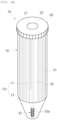
- the blood separation tubes 1a and 1b including a cell activation part include the tube body 10 having a chamber (Ch) for receiving blood.
- a cell activation part that physically collides with centrifuged blood and activates blood cells is provided in a protruding shape on the inner surface of the chamber (Ch) or inside the chamber (Ch).
- the above-described tube body 10 has a hollow cylindrical shape in which an upper inlet side is opened and a chamber (Ch), which is an accommodation space, is formed therein.
- the chamber (Ch) has a hollow cylindrical shape and is divided into an upper chamber 11 and a lower chamber 13.
- the upper chamber 11 has a cylindrical shape having a predetermined diameter and length like the shape of the tube body 10.
- the lower chamber 13 is connected to the upper chamber 11, extends from the lower end of the upper chamber 11, and has a shape gradually narrowing downward.
- the bottom of the lower chamber 13 is sealed.
- a cell activation part configured to physically collide with swirling blood during centrifugation is formed.
- the cell activation part has a structure including any one of a plurality of fine uneven walls formed on the inner surface of the chamber (Ch), having a certain height and width, and configured to protrude in the longitudinal direction and a plurality of fine protrusions 35 ( FIG. 5 ) formed on the inner surface of the chamber (Ch) and configured to protrude.
- the fine uneven walls 31 are radially formed along the inner surface of the chamber (Ch) at a predetermined interval.
- the cell activation part is formed in the upper chamber 11 constituting the chamber (Ch) and has the form of the fine uneven walls 31, but the present invention is not limited thereto.
- the cell activation part may be formed in the lower chamber 13.
- the fine uneven walls 31 formed on the inner surface of the upper chamber 11 are arranged parallel to each other at a predetermined interval with respect to the central axis (C) of the tube body 10. Accordingly, the fine uneven walls 31 are formed to protrude vertically in the longitudinal direction on the inner surface with respect to the tube body 10.
- the fine uneven walls 31 are shown to be formed in the form of a rectangular line protruding toward the central axis (C) side of the inner surface of the chamber, but the present invention is not limited thereto.
- the fine uneven walls 31 may be formed in the form of a semi-cylindrical line or a corrugated column line.
- the fine uneven walls 31 most preferably have a protruding rectangular line shape so that red blood cells having a high specific gravity easily move to the lower chamber side during centrifugation.
- the cell activation part is configured by forming the fine uneven walls 31 at a predetermined interval along the inner circumferential surface on the inner surface of the tube body 10.
- the fine uneven walls 31 are formed continuously and long along the longitudinal direction of the tube body 10.
- the fine uneven walls 31 increase activation rate in blood cells by increasing the collision area with blood and sufficiently applying physical stress to the hemocytes of the blood being centrifuged.
- the cell activation part including the fine uneven walls 31 induces red blood cells having a high specific gravity constituting hemocytes to move easily to the lower portion of the tube body 10 rather than remaining in the upper portion of the tube body 10 during centrifugation, that is, induces red blood cells to move easily to the lower chamber 13 rather than remaining in the upper chamber 11.
- red blood cells in blood do not stay in the upper chamber 11, but move quickly to the lower chamber 13 along the fine uneven walls 31 constituting the cell activation part, so that a clean buffy coat and plasma may be extracted.
- the cell activation part constituting the blood separation tubes 1a and 1b of the present invention further includes the collision partitions 32 formed to have a certain height and width in the longitudinal direction on the inner surface of the chamber (Ch), configured to protrude further toward the central axis than the fine uneven walls 31, and arranged at a predetermined interval.
- the collision partitions 32 are formed to protrude further toward the central axis (C) than the fine uneven walls 31 and to be parallel to the central axis of the tube body 10.
- the collision partitions 32 are provided between the above-described fine uneven walls 31, and the ends thereof are narrowed toward the central axis (C).
- the cross section of the collision partitions 32 has a trapezoidal shape.
- the collision partitions 32 of a trapezoidal shape allow effective collision during centrifugation and facilitate downward movement of red blood cells along the collision partitions 32.
- cross section of the collision barrier 32 is illustrated as a trapezoidal shape, but the present invention is not limited thereto. Any shapes that enable stable collision with blood during centrifugation and allow red blood cells to easily move downward may be used without particular limitation.
- the cell activation part 30 includes the fine uneven walls 31 and the collision partitions 32.
- Fine protrusions 35 FIG. 5 ) having a plurality of embossed patterns may be used instead of the fine uneven walls 31.
- the fine uneven walls 31 and the fine protrusions 35 may be provided in combination.
- the cell activation part is formed in a protruding shape within the tube body 10 to collide with the blood.
- any shapes that may be provided on the inner surface of the chamber (Ch) or inside the chamber (Ch) and may apply physical stress to blood during centrifugation may be used without particular limitation.
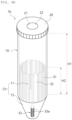
- the cell activation part may also be provided in the lower chamber 13 as shown in FIG. 1B , when necessary.
- the cell activation part formed in the lower chamber 13 may increase the frequency of physical collision with blood during centrifugation. Accordingly, cell separation efficiency may be increased by more effectively applying physical stress to blood.
- the cell activation part formed in the upper chamber 11 may be located in the lower portion of the upper chamber 11.
- the cell activation part may be formed in the lower portion to have a height (H2) corresponding to about 45 to 50 % of the total height (H1) of the upper chamber 11.
- Hemocytes including red blood cells are cellular components that account for about 45 % of the total blood volume. During centrifugation, hemocytes may get caught in the slightly protruding cell activation part. In this case, the hemocytes may not move to the lower portion and thus may not be separated.
- the cell activation part is preferably formed to have a height (H2) lower than the percentage of hemocytes of 45 % relative to the total height (H1) of the upper chamber 11.
- the height (H2) of the cell activation part may be adjusted according to the amount of hemocytes in blood so that the hemocytes and plasma of the centrifuged blood may be perfectly separated.
- the tube body 10 constituting the above-described blood separation tube includes the upper stopper 20 to shield the upper portion of the open chamber (Ch) and maintain airtightness.
- the upper stopper 20 is detachably coupled to the open upper portion of the tube body 10 through fitting or screw coupling and has a packing 22 into which a needle may be inserted.
- This upper stopper is a commonly known structure, and a detailed description thereof will be omitted in order not to obscure the gist of the present invention.
- the blood separation tube 1b including a cell activation part according to the present invention may further include, as a component of the cell activation part, a rod-shaped activation column 33 formed inside the lower chamber 13 and having an outer circumferential surface on which a plurality of fine uneven walls 33a protruding in the longitudinal direction are formed.
- the fine uneven walls 33a are preferably formed at a predetermined interval along the outer circumferential surface of the activation column 33 in the chamber and placed parallel to the central axis.
- the activation column 33 has a predetermined length and is configured to be accommodated inside the lower chamber 13.
- the activation column 33 as in the upper chamber 11, causes collision with white blood cells, lymphocytes, and platelets to occur in the center of the lower chamber 13 from the initial process of centrifugation to more efficiently apply physical stress to blood.
- the activation column 33 serves to bend blood in the lower portion of the tube body 10, i.e., blood in the lower chamber 13, when the blood separation tube rotates in an angle-type centrifugation process.
- white blood cells and platelets with low specific gravity existing between bulky red blood cells may easily rise to the middle layer of the blood separation tube, and a buffy coat may be easily formed.
- the above-described fine uneven walls 33a have the same shape as the fine uneven walls 31 formed on the inner surface of the chamber.
- the present invention is not limited thereto, and the fine uneven walls 33a may be replaced with the fine protrusions 35 as in FIG. 5 , or a combination of fine uneven walls and fine protrusions may be provided.
- FIGS. 5 to 7 are diagrams showing embodiments having cell activation parts according to the shape of the tube body applied to the blood separation tube according to the present invention.
- the blood separation tube including a cell activation part according to the present invention has a shape of the tube body 10 to improve centrifugal separation efficiency.
- Blood separation tubes 1c and 1d including a cell activation part include a tube body having a chamber for receiving blood and a cell activation part formed in a protruding shape on the inner surface of the chamber or inside the chamber to activate blood cells by physical collision with centrifuged blood.
- the chamber (Ch) consists of an upper chamber 11, an intermediate chamber 12, and a lower chamber 13.
- the upper chamber 11 has an open upper portion and is formed in a cylindrical shape having a predetermined diameter and length.
- the intermediate chamber 12 has a narrow tube portion gradually narrowing from the lower end of the upper chamber 11, has a predetermined diameter smaller than the diameter of the upper chamber 11, and has a cylindrical shape extending downward from the narrow tube portion.
- the lower chamber 13 has a wide tube portion that gradually widens from the lower end of the intermediate chamber 12, has a predetermined diameter larger than the diameter of the intermediate chamber 12, and has a cylindrical shape extending downward from the wide tube portion.
- a buffy coat may also be formed in the upper portion of the lower chamber 13 according to the component content of the centrifuged blood.
- the cell activation part including any one of the fine uneven walls 31 formed in a shape protruding in the longitudinal direction with a certain height and width on the inner surface of the chamber (Ch) of the tube body 10 and the fine protrusions 35 formed in a protruding shape on the inner surface of the chamber (Ch) may be formed in the upper chamber 11 or the lower chamber 13.
- the fine uneven walls 31 are formed in the upper chamber 11, and the fine protrusions 35 of an embossed pattern are formed in the lower chamber 13.
- the present invention is not limited to this configuration, and the positions of the fine uneven walls 31 and the fine protrusions 35 may be interchanged or the fine uneven walls 31 and the fine protrusions 35 may be formed in combination.
- the cell activation part may be formed only in the lower chamber 13.
- the cell activation part is preferably formed as shown in FIGS. 5 to 7 .
- the cell activation part preferably further includes the collision partitions 32 formed to have a certain height and width in the longitudinal direction on the inner surface of the upper chamber 11, configured to protrude further toward the central axis than the fine uneven walls 31, and arranged at a predetermined interval.
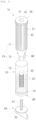
- the lower chamber 13 has a cylindrical shape with an open bottom.
- the bottom of the lower chamber 13 is sealed by a lower portion stopper 40 including a lower portion packing 41 to maintain airtightness.
- the entire or outer circumferential surface of the lower portion packing 41 is preferably formed of an elastic material. In this case, even under centrifugation load, the lower portion packing 41 adheres strongly to the inner surface of the lower chamber 13 to prevent blood from leaking.
- the lower portion packing 41 and the lower portion stopper 40 have been described as separate components, but the lower portion packing may be a lower portion stopper or may be in the form of a stopper separately provided with packing as shown in the figure.
- the lower portion stopper 40 or the lower portion packing 41 ascends or descends along the inner circumferential surface or outer circumferential surface of the lower chamber 13 by an external force according to the shape detachably coupled to the lower chamber 13.
- the lower portion packing 41 is separately combined with the lower portion stopper 40 on the bottom surface of the lower chamber 13, and the lower portion packing 41 inside the lower chamber 13 is pushed by a separate member such as a piston 50 to ascend or descend along the inner circumferential surface of 13 of the lower chamber.
- a separate lift rail 51 as a member for pushing up the lower portion packing 41 may be formed on the outer circumferential surface of the piston 50, and the lower portion packing 41 may be slowly pushed up or down through the lower portion stopper 40 of the tube body 10 corresponding to the lift rail 51.
- the present invention is not limited to this configuration, and a simple rod shape or the like may be used.
- a medical staff may hold the handle 52 and support the piston 50 with the front parts of the fingers, so that the lower portion packing 41 may be pushed up with relatively little force.
- the lower portion stopper 40 has a threaded coupling structure detachably coupled to an external thread 13a formed on the outer circumferential surface of the lower portion of the lower chamber 13. Through this structure, the lower portion stopper 40 moves up and down along the outer circumferential surface of the lower portion of the lower chamber 13.
- lower portion packing (not shown) may be provided on the outer surface of the lower portion of the lower chamber 13.
- the blood separation tube according to the present invention has a rod shape inside the lower chamber 13 as a cell activation part, and may further include the activation column 33 having an outer circumferential surface on which a plurality of the fine uneven walls 33a protruding in the longitudinal direction or fine protrusions (not shown) are formed.
- the activation column 33 is formed in the lower portion stopper 40 or the lower portion packing 41 and has a rod shape. On the outer circumferential surface of the activation column 33, the fine uneven walls 33a protruding in the longitudinal direction are formed.
- the activation column 33 may include a shape of fine protrusions. Since the composition and role of the activation column 33 have been described in FIGS. 4A and 4B , the detailed description will refer to the above description.
- the activation column 33 is accommodated inside the lower chamber 13 by the lower portion stopper 40 or the lower portion packing 41.
- plasma is collected in the upper portion and red blood cells are collected in the lower portion with respect to a buffy coat containing white blood cells and platelets.
- plasma is extracted by inserting a syringe into the plasma layer of the tube body 10 through the upper portion packing 22 of the upper stopper 20, or the buffy coat and plasma are extracted by inserting a syringe into a white blood cell buffy coat of the tube body 10 through the upper portion packing 22.
- the buffy coat only accounts for about 1 % of the total solution and is laid on the red blood cells as thinly as paper in a tube with a substantially wide diameter, it is very difficult even for an expert to separate the buffy coat.
- a thick buffy coat is formed in the intermediate chamber 12 having a narrow diameter, so that the buffy coat may be easily extracted.
- the lower portion packing 41 or the lower portion stopper 40 of the lower chamber 13 is lifted to move a buffy coat in the upper portion of the lower chamber 13 to the intermediate chamber 12 so that the buffy coat may be easily extracted.
- the blood separation tube including a cell activation part of the present invention according to FIGS. 5 to 7 further includes an anti-vibration plate 60 provided integrally on the outer surface of the tube body 10 to prevent vibration of the tube body 10 during centrifugation.
- the anti-vibration plate 60 allows the blood separation tube to be stably positioned in a centrifugal separator, absorbs generated vibration, and keeps the blood separation tube in place.
- the anti-vibration plate 60 prevents the tube body 10 from shaking during centrifugation, thereby preventing blood layers from mixing, facilitating separation and extraction.
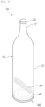
- FIGS. 8 and 9 show another type of tube body included in the blood separation tube including a cell activation part according to the present invention.
- the blood separation tube 1e including a cell activation part has the bottle-shaped tube body 10 having a narrow neck (inlet).
- the chamber (Ch) of the tube body 10 consists of an upper chamber 11' having a predetermined small diameter and length and a lower chamber 13' of a cylindrical shape gradually expanding downward from the lower end of the upper chamber 11' and having a predetermined diameter and length greater than those of the upper chamber 11'.
- the lower chamber 13' has a cylindrical shape with an open bottom surface.
- the bottom surface is sealed by the lower portion packing 41 and the lower portion stopper 40 to maintain airtightness.
- the lower portion packing 41 further includes the rod-shaped activation column 33 having an outer circumferential surface on which the fine uneven walls 33a protruding in the longitudinal direction are formed.
- protruding collision partitions may also be formed on the activation column 33 at a predetermined interval.
- the cell activation part formed on the inner surface of the chamber may be formed on the inner surface of the lower chamber 13'.
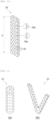
- the cell activation part may include an activation bar 30' having embossed patterns 36 on the outer circumferential surface thereof to cause physical collision while flowing with blood during centrifugation (see FIGS. 6 and 9 ).
- the activation bar 30' has a length (b) greater than the width or diameter (a) ( FIG. 6 ) of the chamber (Ch).
- embossed patterns 36 in the form of fine grooves 36b or fine protrusions 36a are formed.
- the embossed patterns 36 may be composed of the fine protrusions 36a or the fine grooves 36b alone or a combination thereof.
- the activation bar 30' is configured in the form of a bar having a predetermined thickness and length and having a rectangular cross section, but the present invention is not limited thereto.
- Various forms capable of generating physical collision while being included in the chamber (Ch) and flowing with blood during centrifugation may be applied.
- the activation bar 30' may be a cylindrical bar having embossed patterns formed on the outer circumferential surface thereof or a V-shaped bar having embossed patterns formed on the outer circumferential surface thereof.
- the activation bar 30' which constitutes the cell activation part, stirs blood on the lower portion side when the blood separation tube rotates in an angle-type centrifugation process.
- white blood cells and platelets having a low specific gravity existing between bulky red blood cells are easily elevated to the middle layer of the blood separation tube, which increases blood separation efficiency.
- the activation bar 30' may be applied to the embodiments of the present invention. At this time, the activation bar 30' may be applied in combination with the activation column 33 or the activation bar 30' may be applied alone.
- the activation bar 30' may be provided in combination with the fine uneven walls 31, the collision partitions 32, and the fine protrusions 35 constituting the cell activation part, or the activation bar 30' may be provided separately.
- blood is collected from the patient's venous blood or bone marrow, and the collected blood is injected into the chamber (Ch) of the tube body 10 of the blood separation tube according to an embodiment of the present invention.
- the upper stopper 20 is coupled to the opening of the upper portion of the upper chamber 11 constituting the tube body 10, and the opening is sealed with the upper portion packing 22 to maintain airtightness in the chamber (Ch).
- the lower portion stopper 40 having the lower portion packing 41 is coupled to the lower chamber 13 so that the lower chamber 13 is sealed and airtightness in the chamber (Ch) is maintained.
- the chamber (Ch) of the tube body 10 is separated from the outside.
- This structure prevents blood components from being exposed to the outside air during the process of separating the blood components, thereby preventing contamination of blood and increasing the storage period of blood.
- collected blood may be injected into the chamber (Ch) of the tube body 10 through the upper portion packing 22 using a syringe.
- the blood separation tube containing the blood is mounted on the bucket of an angle-type centrifugal separator, and the blood is centrifuged by rotating the centrifugal separator at 2,000 to 4,000 rpm per minute.
- blood components are separated by difference in specific gravity during centrifugation. That is, among blood components, heavy red blood cells sink to the lower chambers 13 and 13' of the chamber (Ch), relatively light monocytes, white blood cells, lymphocytes, and platelets are collected in the center of the chamber (Ch) or the intermediate chamber 12, and plasma is collected in the upper chambers 11 and 11'.
- a vortex of blood occurs in the chamber 11 of the tube body 10, and at this time, hemocytes also flow rapidly. While the blood is flowing, the blood collides with the fine uneven walls 31 formed on the inner surface of the tube body 10, and physical stress is applied to the blood. The blood collides as the blood rotates thousands of times per minute.
- red blood cell layer When centrifugation of blood is completed, due to difference in specific gravity, heavy red blood cells are collected in the lower chamber 13 to form a red blood cell layer, a buffy coat containing white blood cells and platelets is stacked on the red blood cell layer, and a plasma layer is stacked on the buffy coat and is formed in the upper chamber 11. Accordingly, the blood is separated into the red blood cell layer, the buffy coat, and the plasma layer.
- a syringe may be inserted through the upper portion packing 22 into the plasma layer formed in the tube body 10 and plasma may be extracted, or a syringe may be inserted through the upper portion packing 22 into the buffy coat formed in the tube body 10 and the buffy coat and plasma may be extracted.
- extraction may be performed more easily by lifting the lower portion packing 41 or the lower portion stopper 40 to collect the buffy coat in a narrow area.
- the cell activation part may be configured in the form of the activation column 33 or the activation bar 30' in the lower portion of the chamber (Ch).
- the activation column 33 and the activation bar 30' stir blood on the lower portion side of the tube body 10 in an angle-type centrifugation process. Through this operation, white blood cells and platelets having a low specific gravity existing between bulky red blood cells are easily elevated to the middle layer of the blood separation tube, which increases blood separation efficiency.
Landscapes
- Health & Medical Sciences (AREA)
- Life Sciences & Earth Sciences (AREA)
- Chemical & Material Sciences (AREA)
- Hematology (AREA)
- Engineering & Computer Science (AREA)
- General Health & Medical Sciences (AREA)
- Biomedical Technology (AREA)
- Heart & Thoracic Surgery (AREA)
- Analytical Chemistry (AREA)
- Clinical Laboratory Science (AREA)
- Chemical Kinetics & Catalysis (AREA)
- Public Health (AREA)
- Vascular Medicine (AREA)
- Anesthesiology (AREA)
- Animal Behavior & Ethology (AREA)
- Pathology (AREA)
- Physics & Mathematics (AREA)
- Veterinary Medicine (AREA)
- Biophysics (AREA)
- Immunology (AREA)
- General Physics & Mathematics (AREA)
- Biochemistry (AREA)
- Medicinal Chemistry (AREA)
- Food Science & Technology (AREA)
- Urology & Nephrology (AREA)
- Molecular Biology (AREA)
- Ecology (AREA)
- External Artificial Organs (AREA)
- Centrifugal Separators (AREA)
Applications Claiming Priority (3)
| Application Number | Priority Date | Filing Date | Title |
|---|---|---|---|
| KR20200135152 | 2020-10-19 | ||
| KR1020210128834A KR102490576B1 (ko) | 2020-10-19 | 2021-09-29 | 세포 활성화부를 구비한 혈액분리 튜브 |
| PCT/KR2021/014276 WO2022086059A1 (fr) | 2020-10-19 | 2021-10-14 | Tube de séparation de sang comprenant une partie d'activation de cellule |
Publications (2)
| Publication Number | Publication Date |
|---|---|
| EP4230236A1 true EP4230236A1 (fr) | 2023-08-23 |
| EP4230236A4 EP4230236A4 (fr) | 2024-10-09 |
Family
ID=81290710
Family Applications (1)
| Application Number | Title | Priority Date | Filing Date |
|---|---|---|---|
| EP21883130.3A Pending EP4230236A4 (fr) | 2020-10-19 | 2021-10-14 | Tube de séparation de sang comprenant une partie d'activation de cellule |
Country Status (5)
| Country | Link |
|---|---|
| US (1) | US20230390760A1 (fr) |
| EP (1) | EP4230236A4 (fr) |
| JP (1) | JP7640723B2 (fr) |
| CN (1) | CN116368212B (fr) |
| WO (1) | WO2022086059A1 (fr) |
Family Cites Families (21)
| Publication number | Priority date | Publication date | Assignee | Title |
|---|---|---|---|---|
| AU4152085A (en) * | 1984-03-21 | 1985-10-11 | Mclaughlin, W.F. | Method and apparatus for separation of matter from suspension |
| EP0310205B1 (fr) * | 1984-03-21 | 1994-07-20 | McLaughlin, William Francis | Filtration d'une suspension liquide |
| US6045701A (en) * | 1994-10-17 | 2000-04-04 | Baxter International Inc. | Method of filtering a fluid suspension with a membrane having a particular coating |
| US6471855B1 (en) * | 2000-11-22 | 2002-10-29 | Baxter International Inc. | Cassette with integral separation device |
| US7074577B2 (en) * | 2002-10-03 | 2006-07-11 | Battelle Memorial Institute | Buffy coat tube and float system and method |
| US8357296B2 (en) * | 2007-09-24 | 2013-01-22 | Emd Millipore Corporation | Centrifugal filter |
| KR20120129779A (ko) | 2011-05-19 | 2012-11-28 | (주)바이오버드 | 모세관 스트레스 인가에 의한 혈소판 활성화 방법 |
| KR200462858Y1 (ko) * | 2011-12-06 | 2012-10-05 | 이정민 | 원심분리기용 용기 |
| KR101466923B1 (ko) * | 2013-01-17 | 2014-12-04 | 주식회사 휴림바이오셀 | 재생성 세포 추출장치, 재생성 세포 추출 시스템, 이를 이용한 재생성 세포 추출방법 |
| CN103343089B (zh) * | 2013-07-10 | 2014-10-01 | 中国石油大学(华东) | 一种水力空化细胞破壁装置 |
| KR20150029261A (ko) * | 2013-09-10 | 2015-03-18 | 전민용 | 성장인자 추출키트 |
| EP3058367B1 (fr) * | 2013-10-16 | 2019-01-09 | President and Fellows of Harvard College | Dispositif microfluidique pour la surveillance clinique en temps réel et l'évaluation quantitative de la coagulation du sang total |
| KR101429253B1 (ko) | 2014-05-22 | 2014-08-12 | (주) 굿모닝 바이오 | 다채널 혈액 통로를 구비한 혈소판 활성화 장치 |
| EP3174970A1 (fr) * | 2014-07-30 | 2017-06-07 | F. Hoffmann-La Roche AG | Système automatisé de traitement de particules |
| KR101666451B1 (ko) * | 2015-06-01 | 2016-10-14 | 이은혜 | 혈소판이 풍부한 성장인자 추출을 위한 혈액분리 및 추출장치 |
| JP6640998B2 (ja) * | 2015-06-05 | 2020-02-05 | ミメタス ビー.ブイ. | マイクロ流体プレート |
| KR101736374B1 (ko) * | 2016-06-07 | 2017-05-17 | (주)시지바이오 | 원심 분리기용 용기 및 이를 이용한 svf 분리 방법 |
| KR101723341B1 (ko) * | 2016-06-27 | 2017-04-06 | 한국기계연구원 | 미세입자 회수방법 및 미세입자 회수장치 |
| KR102638609B1 (ko) * | 2017-07-27 | 2024-02-19 | 바이오메리욱스, 인코포레이티드. | 격리 튜브 |
| CN207307889U (zh) * | 2017-09-25 | 2018-05-04 | 武汉天之瑞医疗科技有限公司 | 细胞保存液瓶 |
| JP2021531842A (ja) * | 2018-07-09 | 2021-11-25 | ハヌマン ペリカン,インコーポレイテッド | 血液成分を分離するための装置および方法 |
-
2021
- 2021-10-14 US US18/032,557 patent/US20230390760A1/en active Pending
- 2021-10-14 WO PCT/KR2021/014276 patent/WO2022086059A1/fr not_active Ceased
- 2021-10-14 JP JP2023548163A patent/JP7640723B2/ja active Active
- 2021-10-14 EP EP21883130.3A patent/EP4230236A4/fr active Pending
- 2021-10-14 CN CN202180070120.7A patent/CN116368212B/zh active Active
Also Published As
| Publication number | Publication date |
|---|---|
| JP2023546541A (ja) | 2023-11-02 |
| JP7640723B2 (ja) | 2025-03-05 |
| US20230390760A1 (en) | 2023-12-07 |
| WO2022086059A1 (fr) | 2022-04-28 |
| CN116368212A (zh) | 2023-06-30 |
| EP4230236A4 (fr) | 2024-10-09 |
| CN116368212B (zh) | 2026-04-17 |
Similar Documents
| Publication | Publication Date | Title |
|---|---|---|
| US11389616B2 (en) | Method for preparing tissue, particularly adipose tissue, for transplantation from lobular fat extracted by liposuction | |
| US9011687B2 (en) | Method and apparatus for producing autologous clotting components | |
| CN104039372B (zh) | 血液组分分离器 | |
| CN103249425A (zh) | 用于递送白介素-1受体拮抗剂的方法和组合物 | |
| CN102596173A (zh) | 递送白介素-1受体拮抗剂的方法和组合物 | |
| EP3139973B1 (fr) | Dispositif de concentration de bille dans une seringue à dessiccation en une étape | |
| CA3153723A1 (fr) | Dispositif de type centrifugeuse et procede d'utilisation | |
| KR102490576B1 (ko) | 세포 활성화부를 구비한 혈액분리 튜브 | |
| EP4230236A1 (fr) | Tube de séparation de sang comprenant une partie d'activation de cellule | |
| US20230381792A1 (en) | Portable Centrifuge Apparatus & Methods | |
| RU2817650C1 (ru) | Пробирка для разделения крови, содержащая часть активации клеток | |
| KR20220040758A (ko) | 혈액 분리 튜브 및 이를 이용한 세포활성화 방법 | |
| KR20220034417A (ko) | 원심분리기 | |
| EP4291523B1 (fr) | Appareil de centrifugeuse portative | |
| US20230295579A1 (en) | Method and apparatus for mesenchymal stem cells purification | |
| KR101569172B1 (ko) | 성분 분리장치 | |
| EP4419254A1 (fr) | Tube destiné à un procédé avancé d'obtention de fibrine riche en plaquettes | |
| CN2047566U (zh) | 注射药剂容器及其注射器具 |
Legal Events
| Date | Code | Title | Description |
|---|---|---|---|
| STAA | Information on the status of an ep patent application or granted ep patent |
Free format text: STATUS: THE INTERNATIONAL PUBLICATION HAS BEEN MADE |
|
| PUAI | Public reference made under article 153(3) epc to a published international application that has entered the european phase |
Free format text: ORIGINAL CODE: 0009012 |
|
| STAA | Information on the status of an ep patent application or granted ep patent |
Free format text: STATUS: REQUEST FOR EXAMINATION WAS MADE |
|
| 17P | Request for examination filed |
Effective date: 20230424 |
|
| AK | Designated contracting states |
Kind code of ref document: A1 Designated state(s): AL AT BE BG CH CY CZ DE DK EE ES FI FR GB GR HR HU IE IS IT LI LT LU LV MC MK MT NL NO PL PT RO RS SE SI SK SM TR |
|
| DAV | Request for validation of the european patent (deleted) | ||
| DAX | Request for extension of the european patent (deleted) | ||
| A4 | Supplementary search report drawn up and despatched |
Effective date: 20240911 |
|
| RIC1 | Information provided on ipc code assigned before grant |
Ipc: B01L 3/00 20060101ALI20240905BHEP Ipc: C12M 1/00 20060101ALI20240905BHEP Ipc: A61M 1/02 20060101AFI20240905BHEP |