EP4230331A1 - Outil de perçage étagé - Google Patents
Outil de perçage étagé Download PDFInfo
- Publication number
- EP4230331A1 EP4230331A1 EP22157784.4A EP22157784A EP4230331A1 EP 4230331 A1 EP4230331 A1 EP 4230331A1 EP 22157784 A EP22157784 A EP 22157784A EP 4230331 A1 EP4230331 A1 EP 4230331A1
- Authority
- EP
- European Patent Office
- Prior art keywords
- tool
- drill
- adapter
- shank
- drilling tool
- Prior art date
- Legal status (The legal status is an assumption and is not a legal conclusion. Google has not performed a legal analysis and makes no representation as to the accuracy of the status listed.)
- Pending
Links
- 238000005553 drilling Methods 0.000 title claims abstract description 57
- 238000003801 milling Methods 0.000 claims abstract description 27
- 238000009413 insulation Methods 0.000 claims abstract description 19
- 239000000758 substrate Substances 0.000 claims abstract description 12
- 239000002131 composite material Substances 0.000 claims abstract description 8
- 239000011810 insulating material Substances 0.000 claims abstract description 8
- 230000005540 biological transmission Effects 0.000 claims abstract description 7
- 238000003780 insertion Methods 0.000 claims description 14
- 230000037431 insertion Effects 0.000 claims description 14
- 230000000694 effects Effects 0.000 claims description 5
- 239000012774 insulation material Substances 0.000 description 3
- 229910000997 High-speed steel Inorganic materials 0.000 description 2
- 239000004793 Polystyrene Substances 0.000 description 2
- 238000010276 construction Methods 0.000 description 2
- 239000000463 material Substances 0.000 description 2
- 239000011490 mineral wool Substances 0.000 description 2
- 229920002223 polystyrene Polymers 0.000 description 2
- 229910052582 BN Inorganic materials 0.000 description 1
- PZNSFCLAULLKQX-UHFFFAOYSA-N Boron nitride Chemical compound N#B PZNSFCLAULLKQX-UHFFFAOYSA-N 0.000 description 1
- 230000001066 destructive effect Effects 0.000 description 1
- 229910003460 diamond Inorganic materials 0.000 description 1
- 239000010432 diamond Substances 0.000 description 1
- 238000007373 indentation Methods 0.000 description 1
- 238000000926 separation method Methods 0.000 description 1
Images


Classifications
-
- B—PERFORMING OPERATIONS; TRANSPORTING
- B25—HAND TOOLS; PORTABLE POWER-DRIVEN TOOLS; MANIPULATORS
- B25D—PERCUSSIVE TOOLS
- B25D17/00—Details of, or accessories for, portable power-driven percussive tools
- B25D17/08—Means for retaining and guiding the tool bit, e.g. chucks allowing axial oscillation of the tool bit
- B25D17/084—Rotating chucks or sockets
- B25D17/088—Rotating chucks or sockets with radial movable locking elements co-operating with bit shafts specially adapted therefor
-
- B—PERFORMING OPERATIONS; TRANSPORTING
- B23—MACHINE TOOLS; METAL-WORKING NOT OTHERWISE PROVIDED FOR
- B23B—TURNING; BORING
- B23B51/00—Tools for drilling machines
- B23B51/08—Drills combined with tool parts or tools for performing additional working
-
- B—PERFORMING OPERATIONS; TRANSPORTING
- B25—HAND TOOLS; PORTABLE POWER-DRIVEN TOOLS; MANIPULATORS
- B25D—PERCUSSIVE TOOLS
- B25D17/00—Details of, or accessories for, portable power-driven percussive tools
- B25D17/02—Percussive tool bits
-
- B—PERFORMING OPERATIONS; TRANSPORTING
- B23—MACHINE TOOLS; METAL-WORKING NOT OTHERWISE PROVIDED FOR
- B23B—TURNING; BORING
- B23B2226/00—Materials of tools or workpieces not comprising a metal
- B23B2226/39—Foam
-
- B—PERFORMING OPERATIONS; TRANSPORTING
- B23—MACHINE TOOLS; METAL-WORKING NOT OTHERWISE PROVIDED FOR
- B23B—TURNING; BORING
- B23B2226/00—Materials of tools or workpieces not comprising a metal
- B23B2226/75—Stone, rock or concrete
-
- B—PERFORMING OPERATIONS; TRANSPORTING
- B23—MACHINE TOOLS; METAL-WORKING NOT OTHERWISE PROVIDED FOR
- B23B—TURNING; BORING
- B23B49/00—Measuring or gauging equipment on boring machines for positioning or guiding the drill; Devices for indicating failure of drills during boring; Centering devices for holes to be bored
- B23B49/003—Stops attached to drilling tools, tool holders or drilling machines
- B23B49/005—Attached to the drill
-
- B—PERFORMING OPERATIONS; TRANSPORTING
- B25—HAND TOOLS; PORTABLE POWER-DRIVEN TOOLS; MANIPULATORS
- B25D—PERCUSSIVE TOOLS
- B25D2222/00—Materials of the tool or the workpiece
- B25D2222/54—Plastics
- B25D2222/69—Foamed polymers, e.g. polyurethane foam
-
- B—PERFORMING OPERATIONS; TRANSPORTING
- B25—HAND TOOLS; PORTABLE POWER-DRIVEN TOOLS; MANIPULATORS
- B25D—PERCUSSIVE TOOLS
- B25D2250/00—General details of portable percussive tools; Components used in portable percussive tools
- B25D2250/055—Depth properties, e.g. tools having depth indicator or depth control
Definitions
- the invention relates to a stepped drilling tool with a tool longitudinal axis for making boreholes with different diameters in a substrate and an insulating material layer of a thermal insulation composite system lying against the substrate.
- a layer of insulation material made of insulation boards for example made of polystyrene or high-density mineral wool, is usually glued to the substrate, then dowelled and then plastered.
- underground also includes any type of substructure on which the insulation boards are mounted.
- the thickness of the insulating material layer in thermal insulation composite systems continues to increase.
- Insulation panels made of polystyrene or mineral wool with a thickness of 120-400mm and even more are currently used for thermal insulation of facades.
- the insulation panels are partially fixed with insulation material dowels that have a stepped shaft.
- the expansion zone has a diameter of 8mm, for example, which is followed by an expanded shaft with a diameter of 12-30mm.
- Stepped drilling tools that have at least two steps are used to make such bores.
- the first stage has a measure according to what is needed Borehole diameter in the substrate, the second stage a dimension corresponding to the borehole diameter in the insulation board.
- step drills of this type are sometimes not available as special tools at the construction site and are expensive.
- the Stepped drilling tool features an adapter with a milling head, an interchangeable masonry bit, a drive rod and an SDS drive shaft for connection to a drill.
- the drive rod connects to the SDS shaft and merges into the adapter with a tool holder designed as a hollow cone.
- the tool holder accommodates a drill shank of the masonry drill designed as a Morse taper.
- the adapter has a transverse opening through which a wedge must be driven in order to drive the Morse taper out of the tool holder.
- the entire adapter with milling head can be damaged in such a way that the step drilling tool can no longer be used.
- the invention is based on the object of creating a step drilling tool of the type mentioned at the outset, which allows problem-free, in particular non-destructive, replacement of the drill of the first step.
- the operating costs of the step drilling tool when drilling boreholes in a substrate and a layer of insulating material lying against the substrate should be reduced.
- An open groove in the direction of the longitudinal axis of the tool is understood to mean a groove that is open on the face of the insertion end of the drill shank.
- a closed groove is understood to mean a groove that runs in the direction of the longitudinal axis of the tool and is completely embedded in the lateral surface of the cylindrical insertion end.
- the drill lock is designed in such a way that the locking element engages in the closed groove, However, no clamping effect exerts on the shank of the drill. As a result, the locking element assumes the function of axially securing the drill bit in the adapter, but without preventing a relative movement in the direction of the longitudinal tool axis between the locking element and the closed groove.
- the step drilling tool according to the invention allows in particular the use of conventional masonry or concrete drills with an SDS drill shank or an SDS-Plus drill shank, which can be inserted into the tool holder of the adapter.
- the invention therefore enables the use of inexpensive, readily available standard drills and thus reduces the operating costs of the step drilling tool.
- Each driver for torque transmission between the insertion end and the tool holder is designed as a pin, which extends in the radial direction to the longitudinal tool axis, is attached to the adapter and positively engages in the open groove.
- the attachment to the adapter can, for example, take place in that the pins are inserted by means of a press fit into corresponding passages in the wall of the adapter and at the end into the tool holder forming Protrude the hollow cylinder so far that the insertion end with the open grooves guided by the pin ends can be inserted into the tool holder.
- the at least one further stage of the stepped drilling tool arranged on the adapter is designed as a milling tool, preferably as a face milling cutter, also referred to as a milling head.
- the at least one milling tool is preferably detachably connected to the adapter and has a tool body that carries the cutting edges.
- the detachable connection between the adapter and the milling tool preferably comprises at least one external thread and one internal thread arranged in the tool body of the milling tool.
- the external thread can be located on the lateral surface of the adapter and/or on a socket of the adapter with a reduced diameter at the end.
- the milling tool for a second stage can be screwed onto the socket and, if available, a milling tool with larger external dimensions for a third stage can be screwed onto the external thread on the lateral surface of the adapter.
- the drive rod is detachably connected to the adapter and preferably also detachably connected to the drive shaft.
- a drive rod that is adjusted in length to the depth of the drill hole connects the drive shaft and the adapter with each other.
- Another way to adjust the length of the drive rod is that the drive rod is in several parts and the several parts are detachably connected to each other. The length adjustment can then be accomplished by connecting a different number of parts of the drive rod.
- the individual components of the step drilling tool i.e. drill bit, adapter, drive rod or parts of the drive rod and drive shaft, can be assembled as required on the construction site in the manner of a modular system.
- the drive shank can be designed, for example, as a cylinder, as a polygon or as an SDS shank.
- the detachable connection between the drive rod and the adapter and between the drive rod and the drive shaft is preferably a screw connection.
- the screw connection is preferably made by threaded rods which engage in internal threads at the ends of the two connection partners. Depending on the material, however, external and internal threads can also be provided at the ends of the connection partners.
- a stop is arranged on the drive rod so that it can be displaced and locked in the direction of the longitudinal tool axis.
- the drive rod can, for example, have a plurality of ring-shaped depressions which are arranged at a distance and parallel to one another and into which latching means arranged on the depth stop engage.
- High-speed steel (HSS) and carbide, boron nitride or diamond for the cutting edges of the first stage can be considered as materials for the step drilling tool.
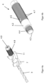
- figure 1 shows a two-stage stepped drilling tool (1) with a tool longitudinal axis (2) for making boreholes with different diameters in a substrate and an insulating material layer of a thermal insulation composite system lying against the substrate.
- the step drilling tool (1) comprises as essential components a drill (3), an adapter (4), a drive shaft (5) to connect the step drilling tool (1) to the output of a drill (not shown), and a drive rod (6), which connects the drive shaft (5) and the adapter (4) to one another.
- the drill (3) consists of a drill shank (3.1) and a drill head (3.2).
- a commercially available twist drill with an SDS drill shank is shown in the exemplary embodiment.
- the drill shank (3.1) is designed as a cylindrical shank.
- Two diametrically opposed, open grooves (3.3) are made in the shank for torque transmission.
- two opposite, closed grooves (3.4) are introduced into the shank.
- the closed grooves (3.4) are offset by 90 degrees to the open grooves (3.3) on the circumference of the drill shank (3.1) and extend like the open grooves (3.3) in the direction of the longitudinal tool axis (2).
- the open grooves (3.3) are open towards the end of the drill shank (3.1).
- the adapter (4) features like this particular Figures 3a, 3d can be seen, a tool holder (4.1) designed as a hollow cylinder, which receives the insertion end of the drill (3).
- the hollow-cylindrical tool holder (4.1) is limited by an annular wall (4.2) which tapered at the front to form a tubular socket (4.3) with an external thread (4.4).
- a milling tool (7) with a corresponding internal thread can be screwed onto the external thread (4.4).
- the milling tool (7) forms the second stage of the step drilling tool (1).
- two blind hole threads (4.5) are arranged in the wall (4.2) of the adapter (4).
- a thread-free passage (4.6) with a smaller diameter extends from a base area of the blind hole thread (4.5) to the hollow-cylindrical tool holder (4.1).
- Both the blind hole thread (4.5) and the passage (4.6) are arranged in the radial direction to the longitudinal tool axis (2).
- two pin receptacles (4.7) are arranged opposite each other.
- a threaded pin (8) can be screwed into each of the two blind hole threads (4.5) until it rests against the base of the blind hole thread (4.5).
- the threaded pin (8) has a rotary drive (8.1), for example for a Torx drive, and at a front end a non-threaded pin (8.2) with a rounded end.
- the pin (8.2) is formed by a cylindrical pin delimited on one end by a cap.
- Pins (9) are inserted into the pin receptacles (4.7) in the wall (4.2) of the adapter (4) as drivers, which extend in the radial direction to the longitudinal tool axis (2) into the hollow-cylindrical tool receptacle (4.1) and each have a positive fit engage in one of the two open grooves (3.3) of the insertion end of the drill (3).
- the torque is transmitted to the drill shank (3.1) of the drill (3) by the adapter (4), which rotates during drilling, via the two pins (9) arranged diametrically opposite one another in the receptacles (4.7).
- the drill (3) can easily be replaced with a commercially available drill (3) with an SDS shank by loosening the threaded pins (8 ) on both sides of the adapter can be temporarily unscrewed using the rotary drive (8.1) so that the spigot (8.2) of the two set screws (8) releases the closed grooves (3.4) provided for axial securing in the shank of the drill (3).
- the shank of the drill (3) can be pulled out of the tool holder (4.1). the pins (9) slide out of the open grooves (3.3) in the shank.
- the setscrews (8) are screwed in until they rest against the base of the blind hole thread (4.5), thereby securing the new drill (3) in the tool holder (4.1) so that it cannot be lost.
- the drive rod (6) is releasably connected both to the drive shaft (5) and to the adapter (4).
- the detachable connection on both sides of the drive rod (6) is a screw connection.
- the screw connection between the adapter (4) and the drive rod (6) comprises a threaded rod (10) which is screwed into an internal thread (4.9) on the rear end of the adapter (4) (cf. Figure 3a ) and an internal thread (6.1) engages on the front side of the drive rod (6) (cf. figure 1 ).
- On the back of the drive rod (6) there is a further internal thread (6.2) into which an external thread (5.1) arranged on the front of the drive shaft (5) can be screwed.
- the threaded rod (6) can be replaced with a longer or shorter threaded rod (6) to adjust the length of the stepped drilling tool (1) to insulation layers of different thicknesses.
- the drive shaft (5) is designed as an SDS shaft for a corresponding receptacle in a drill and therefore has two opposite shafts corresponding to the drill shaft (3.1). open grooves (5.2) and two oppositely arranged closed grooves (5.3).
- Figures 4a, 4b show a compared to the embodiment Figures 1 -3 modified adapter (4) required for a three-stage step drilling tool (1).
- Deviating from the embodiment according to the Figures 1-3 is not only on the external thread (4.4) of the tubular socket (4.3) a first milling tool (7) to form the second stage, but also on a further external thread (4.8) on the lateral surface of the cylindrical adapter (4) a further milling tool ( 11) screwed on to form the third stage.
- the additional milling tool (11) forming the third stage has a larger external dimension than the milling tool (7) for the second stage, corresponding to the drill hole diameter required for the third stage.
- a depth stop (12) can be arranged on its drive rod (6) to limit the depth of the drill hole in the direction of the longitudinal tool axis (2) and can be locked in place.
- the drive rod (6) has several spaced-apart ring-shaped depressions (6.3).
- a latching means arranged on it engages in the ring-shaped depression (6.3) and thereby locks the depth stop.
Landscapes
- Engineering & Computer Science (AREA)
- Mechanical Engineering (AREA)
- Drilling Tools (AREA)
Priority Applications (1)
| Application Number | Priority Date | Filing Date | Title |
|---|---|---|---|
| EP22157784.4A EP4230331A1 (fr) | 2022-02-21 | 2022-02-21 | Outil de perçage étagé |
Applications Claiming Priority (1)
| Application Number | Priority Date | Filing Date | Title |
|---|---|---|---|
| EP22157784.4A EP4230331A1 (fr) | 2022-02-21 | 2022-02-21 | Outil de perçage étagé |
Publications (1)
| Publication Number | Publication Date |
|---|---|
| EP4230331A1 true EP4230331A1 (fr) | 2023-08-23 |
Family
ID=80446007
Family Applications (1)
| Application Number | Title | Priority Date | Filing Date |
|---|---|---|---|
| EP22157784.4A Pending EP4230331A1 (fr) | 2022-02-21 | 2022-02-21 | Outil de perçage étagé |
Country Status (1)
| Country | Link |
|---|---|
| EP (1) | EP4230331A1 (fr) |
Citations (7)
| Publication number | Priority date | Publication date | Assignee | Title |
|---|---|---|---|---|
| DE29508159U1 (de) | 1995-05-17 | 1995-08-03 | Halamay, Klaus, Dipl.-Ing. (FH), 86420 Diedorf | Stufenbohrer für Beton und Mauerwerk |
| DE202008011892U1 (de) * | 2008-09-05 | 2008-12-18 | Schlagmann Baustoffwerke Gmbh & Co. Kg | Bohrwerkzeug |
| EP2959995A1 (fr) * | 2014-06-23 | 2015-12-30 | EJOT Baubefestigungen GmbH | Outil de montage et procédé d'installation en retrait d'une rosace de cheville |
| GB2547627A (en) * | 2015-12-17 | 2017-08-30 | Jens Polanetz-Otto | Improved fixing |
| WO2019074871A1 (fr) * | 2017-10-10 | 2019-04-18 | Milwaukee Electric Tool Corporation | Outil électrique pour adaptateur d'extension de mèche d'outil |
| CN110202189A (zh) * | 2019-07-18 | 2019-09-06 | 苏州迈卡孚工业科技有限公司 | 一种高强韧钢复合工业刀具 |
| WO2021021858A1 (fr) * | 2019-08-01 | 2021-02-04 | Milwaukee Electric Tool Corporation | Ensemble trépan à vide avec mèche remplaçable |
-
2022
- 2022-02-21 EP EP22157784.4A patent/EP4230331A1/fr active Pending
Patent Citations (7)
| Publication number | Priority date | Publication date | Assignee | Title |
|---|---|---|---|---|
| DE29508159U1 (de) | 1995-05-17 | 1995-08-03 | Halamay, Klaus, Dipl.-Ing. (FH), 86420 Diedorf | Stufenbohrer für Beton und Mauerwerk |
| DE202008011892U1 (de) * | 2008-09-05 | 2008-12-18 | Schlagmann Baustoffwerke Gmbh & Co. Kg | Bohrwerkzeug |
| EP2959995A1 (fr) * | 2014-06-23 | 2015-12-30 | EJOT Baubefestigungen GmbH | Outil de montage et procédé d'installation en retrait d'une rosace de cheville |
| GB2547627A (en) * | 2015-12-17 | 2017-08-30 | Jens Polanetz-Otto | Improved fixing |
| WO2019074871A1 (fr) * | 2017-10-10 | 2019-04-18 | Milwaukee Electric Tool Corporation | Outil électrique pour adaptateur d'extension de mèche d'outil |
| CN110202189A (zh) * | 2019-07-18 | 2019-09-06 | 苏州迈卡孚工业科技有限公司 | 一种高强韧钢复合工业刀具 |
| WO2021021858A1 (fr) * | 2019-08-01 | 2021-02-04 | Milwaukee Electric Tool Corporation | Ensemble trépan à vide avec mèche remplaçable |
Similar Documents
| Publication | Publication Date | Title |
|---|---|---|
| WO1994025763A1 (fr) | Vis a former les filetages | |
| EP1870533A1 (fr) | Cheville et procédé de montage de plaques de matériau isolant | |
| EP0870561B1 (fr) | Outil de forage | |
| EP3882475A1 (fr) | Cheville en placoplâtre et combinaison de la cheville en placoplâtre avec un outil de perçage et de tournage | |
| DE2535066A1 (de) | Verfahren zum spreizdruckfreien setzen von duebeln sowie werkzeug und duebel zur durchfuehrung des verfahrens | |
| EP0375606A1 (fr) | Dispositif d'attache | |
| EP0343653B1 (fr) | Outil à fraiser et procédé pour agrandir des trous de type cylindrique | |
| EP2535601A1 (fr) | Vis d'ancrage | |
| EP3656494A1 (fr) | Foret étagé | |
| DE102010017267B3 (de) | Selbstbohrende Schraube | |
| DE3718158A1 (de) | Vorrichtung zur erzeugung einer hinterschneidung in einem zylindrisch vorgebohrten bohrloch und ankerstange zum einsetzen in ein bohrloch | |
| EP4230331A1 (fr) | Outil de perçage étagé | |
| WO2003008763A1 (fr) | Assemblage d'une tige d'ancrage et d'un outil de forage | |
| EP0038917B1 (fr) | Unité de perçage destinée à fabriquer des trous | |
| DE4014381A1 (de) | Werkzeug zur wahlweisen herstellung von ausnehmungen, bohrungen oder gewindebohrungen im vollen material | |
| AT522202B1 (de) | Bohrwerkzeug | |
| DE3811249A1 (de) | Befestigungseinrichtung eines gewindebauteils in einem hinterschnittenen bohrloch und bohrvorrichtung zum herstellen von hinterschneidungen | |
| DE4326000A1 (de) | Stiftbohrkrone für das schlagende Bohren | |
| EP1251238A1 (fr) | Marteau à percussion pour roches | |
| EP1400704A1 (fr) | Dispositif pour la fixation à distance de plaques d'isolation aux murs ou aux plafonds | |
| AT402335B (de) | Justierdübelsystem zur einstellbaren verbindung zweier elemente miteinander sowie eine gewindehülse, eine verankerungshülse, ein verankerungselement und eine bohrhilfe für das justierdübelsystem | |
| WO1991008072A2 (fr) | Systeme de serrage permettant de relier des pieces de façon a eviter leur rotation ou leur deplacement cyclique | |
| EP3959056A1 (fr) | Système de fixation d'un ancrage dans un substrat minéral | |
| DE3908646C2 (fr) | ||
| EP3296045A1 (fr) | Foret |
Legal Events
| Date | Code | Title | Description |
|---|---|---|---|
| PUAI | Public reference made under article 153(3) epc to a published international application that has entered the european phase |
Free format text: ORIGINAL CODE: 0009012 |
|
| STAA | Information on the status of an ep patent application or granted ep patent |
Free format text: STATUS: THE APPLICATION HAS BEEN PUBLISHED |
|
| AK | Designated contracting states |
Kind code of ref document: A1 Designated state(s): AL AT BE BG CH CY CZ DE DK EE ES FI FR GB GR HR HU IE IS IT LI LT LU LV MC MK MT NL NO PL PT RO RS SE SI SK SM TR |
|
| STAA | Information on the status of an ep patent application or granted ep patent |
Free format text: STATUS: REQUEST FOR EXAMINATION WAS MADE |
|
| 17P | Request for examination filed |
Effective date: 20231020 |
|
| RBV | Designated contracting states (corrected) |
Designated state(s): AL AT BE BG CH CY CZ DE DK EE ES FI FR GB GR HR HU IE IS IT LI LT LU LV MC MK MT NL NO PL PT RO RS SE SI SK SM TR |