EP4230785B1 - Système de dosage destiné à la distribution d'au moins une préparation fluide dans un espace intérieur d'un lave-linge - Google Patents
Système de dosage destiné à la distribution d'au moins une préparation fluide dans un espace intérieur d'un lave-linge Download PDFInfo
- Publication number
- EP4230785B1 EP4230785B1 EP22157798.4A EP22157798A EP4230785B1 EP 4230785 B1 EP4230785 B1 EP 4230785B1 EP 22157798 A EP22157798 A EP 22157798A EP 4230785 B1 EP4230785 B1 EP 4230785B1
- Authority
- EP
- European Patent Office
- Prior art keywords
- dosing
- dosing system
- pump
- container
- rotating body
- Prior art date
- Legal status (The legal status is an assumption and is not a legal conclusion. Google has not performed a legal analysis and makes no representation as to the accuracy of the status listed.)
- Active
Links
Images


Classifications
-
- D—TEXTILES; PAPER
- D06—TREATMENT OF TEXTILES OR THE LIKE; LAUNDERING; FLEXIBLE MATERIALS NOT OTHERWISE PROVIDED FOR
- D06F—LAUNDERING, DRYING, IRONING, PRESSING OR FOLDING TEXTILE ARTICLES
- D06F33/00—Control of operations performed in washing machines or washer-dryers
- D06F33/30—Control of washing machines characterised by the purpose or target of the control
- D06F33/32—Control of operational steps, e.g. optimisation or improvement of operational steps depending on the condition of the laundry
- D06F33/37—Control of operational steps, e.g. optimisation or improvement of operational steps depending on the condition of the laundry of metering of detergents or additives
-
- D—TEXTILES; PAPER
- D06—TREATMENT OF TEXTILES OR THE LIKE; LAUNDERING; FLEXIBLE MATERIALS NOT OTHERWISE PROVIDED FOR
- D06F—LAUNDERING, DRYING, IRONING, PRESSING OR FOLDING TEXTILE ARTICLES
- D06F39/00—Details of washing machines not specific to a single type of machines covered by groups D06F9/00 - D06F27/00
- D06F39/02—Devices for adding soap or other washing agents
- D06F39/024—Devices for adding soap or other washing agents mounted on the agitator or the rotating drum; Free body dispensers
-
- D—TEXTILES; PAPER
- D06—TREATMENT OF TEXTILES OR THE LIKE; LAUNDERING; FLEXIBLE MATERIALS NOT OTHERWISE PROVIDED FOR
- D06F—LAUNDERING, DRYING, IRONING, PRESSING OR FOLDING TEXTILE ARTICLES
- D06F34/00—Details of control systems for washing machines, washer-dryers or laundry dryers
- D06F34/14—Arrangements for detecting or measuring specific parameters
-
- D—TEXTILES; PAPER
- D06—TREATMENT OF TEXTILES OR THE LIKE; LAUNDERING; FLEXIBLE MATERIALS NOT OTHERWISE PROVIDED FOR
- D06F—LAUNDERING, DRYING, IRONING, PRESSING OR FOLDING TEXTILE ARTICLES
- D06F39/00—Details of washing machines not specific to a single type of machines covered by groups D06F9/00 - D06F27/00
- D06F39/02—Devices for adding soap or other washing agents
- D06F39/022—Devices for adding soap or other washing agents in a liquid state
-
- F—MECHANICAL ENGINEERING; LIGHTING; HEATING; WEAPONS; BLASTING
- F04—POSITIVE - DISPLACEMENT MACHINES FOR LIQUIDS; PUMPS FOR LIQUIDS OR ELASTIC FLUIDS
- F04B—POSITIVE-DISPLACEMENT MACHINES FOR LIQUIDS; PUMPS
- F04B13/00—Pumps specially modified to deliver fixed or variable measured quantities
-
- F—MECHANICAL ENGINEERING; LIGHTING; HEATING; WEAPONS; BLASTING
- F04—POSITIVE - DISPLACEMENT MACHINES FOR LIQUIDS; PUMPS FOR LIQUIDS OR ELASTIC FLUIDS
- F04B—POSITIVE-DISPLACEMENT MACHINES FOR LIQUIDS; PUMPS
- F04B43/00—Machines, pumps, or pumping installations having flexible working members
- F04B43/12—Machines, pumps, or pumping installations having flexible working members having peristaltic action
-
- D—TEXTILES; PAPER
- D06—TREATMENT OF TEXTILES OR THE LIKE; LAUNDERING; FLEXIBLE MATERIALS NOT OTHERWISE PROVIDED FOR
- D06F—LAUNDERING, DRYING, IRONING, PRESSING OR FOLDING TEXTILE ARTICLES
- D06F2105/00—Systems or parameters controlled or affected by the control systems of washing machines, washer-dryers or laundry dryers
- D06F2105/42—Detergent or additive supply
Definitions
- the invention relates to a dosing system for dispensing at least one flowable preparation into an interior of a washing machine, comprising at least one dosing device and at least one container that can be coupled to the dosing device for storing the at least one flowable preparation.
- Such dosing systems are used to dispense free-flowing preparations such as detergents in a user-friendly manner and to automate the dosing process as far as possible and to optimise the washing result.
- the WO 2011/134690 A1 shows a dosing system for use in the interior of a washing machine.
- a preparation stored in the system for treating laundry in the washing machine is dispensed from a container by means of movement of a closure element by an actuator.
- WO 2017/167658 A1 describes a dosing device for use in the interior of a washing machine, which has valves that can be opened for dosing as required.
- drum washing machines the laundry is applied to the wall of the suds container in various phases of the washing process by increasing the drum speed. The speeds reach 400 rpm to 1600 rpm. A high centrifugal force acts on the dosing device located in the suds container. This also affects the flowable preparations stored in the dosing device.
- the valves for the product outlet are exposed to high pressure forces (overpressure or underpressure), particularly during the spinning process. Movable valves with elastic seals are not designed for such pressure loads.
- valves for dosing flowable preparations in dosing devices for use in suds containers of washing machines is therefore disadvantageous in terms of safe dosing and maintaining the functionality of the dosing device.
- simple closure elements and valves are not suitable for achieving a high level of dosing accuracy even when dispensing very small quantities of the flowable preparation.
- a dosing device with a peristaltic pump is made of US2021/189631A known.
- the invention proposes a dosing system according to the features of patent claim 1.
- a dosing system for dispensing at least one flowable preparation into an interior of a washing machine, which comprises at least one dosing device and at least one container that can be coupled to the dosing device for storing the at least one flowable preparation.
- the flowable preparation can be, for example, a detergent, detergent component, fragrance, bleach or solvent.
- the container that can be coupled to the dosing device is preferably designed such that it offers sufficient space for storing the at least one flowable preparation sufficient for several washing processes, particularly preferably sufficient for 5 to 25 washing processes.
- the dosing device has at least one electrical energy source for operating the dosing device.
- the dosing device can be designed in the form of one or more batteries or rechargeable batteries, for example lithium polymer batteries, and supplies the other components of the dosing device with electrical energy.
- the dosing device also comprises at least one dosing unit for dispensing a predefined amount of the at least one flowable preparation, at least one sensor unit for monitoring the dosing unit and at least one control unit coupled to the dosing unit and the sensor unit.
- the dosing unit has a pump for dispensing the at least one flowable preparation.
- the dosing unit can preferably have a motor and a gear for driving the pump.
- the electrical energy source of the dosing device can supply the motor with electrical energy in order to ensure that the dosing process runs smoothly.
- the dosing system is suitable for free positioning within the interior of the washing machine, preferably it is suitable for free positioning within the tub of a drum washing machine. Preferably it is designed to be stable enough to withstand spin cycles within the washing machine at 100 rpm, particularly preferably up to 1600 rpm without damage.
- the dosing unit with a pump, it is suitable for continuing to dose reliably under the influence of gravity of >1g and at the same time sealing tightly against unwanted leakage of the flowable preparation and against the ingress of air and/or water into the dosing system.
- it can, for example, have one or more protective housings for individual components of the dosing system in order to protect sensitive components from damage caused by mechanical impact.
- the pump is designed as a peristaltic pump.
- Peristaltic pumps offer the advantage that they function reliably even when exposed to high external forces, such as those that occur inside the tub during a washing process.
- a dosing unit designed in this way can ensure that reliable, precise dosing is possible at all times.
- high dosing accuracy can be achieved with peristaltic pumps, even with very small dispensing quantities in the milliliter and sub-milliliter range.
- the peristaltic pump comprises a rotating body eccentrically mounted within a holder for conveying the at least one flowable preparation through a pump hose.
- the pump hose is mounted in the holder around the rotating body. Due to the eccentric mounting on an axis, for example in the form of a pump shaft, the part of the rotating body that has the greatest extension starting from the axis compresses a part of the pump hose to the maximum. If the rotating body, driven by the axis connected to the gear and the motor of the dosing unit, is rotated about this axis, the point of maximum load on the pump hose moves with the rotation. The rotating body continuously conveys the flowable preparation in the pump hose through it. An exact flow rate can be determined by the rotation speed and frequency of rotation of the rotating body and can be adjusted by the control unit as required.
- the rotating body can be controlled by the control unit using at least one signal transmitted by the sensor unit.
- the sensor unit can detect the position of the rotating body and transmit this to the control unit for comparison.
- the control unit can then in turn issue a control command to the dosing unit that is adapted to the desired dispensing quantity of the flowable preparation and the current angular position of the rotating body, so that the dosing accuracy is constantly consistently high.
- the sensor unit has at least one Hall sensor and the rotating body has at least one magnet.
- the position of the eccentric rotating body can be easily and precisely detected using the Hall sensor. As soon as the magnet located at a predetermined position on the rotating body passes through the detection range of the Hall sensor, the exact position of the rotating body can be determined. In combination with a predetermined rotation speed, it is possible to always move the rotating body to a desired position. to continue to rotate and thus to dispense exactly the desired amount of the flowable preparation, which is specified by the control unit to the dosing unit.
- the magnet is located in the area of the rotating body that compresses the pump hose to the maximum. This embodiment is characterized by its functional reliability even under the influence of high forces, for example when the suds container is rotating at an increased speed.
- the rotating body can be moved by the control unit into a valve position for tightly sealing the peristaltic pump.
- the sealing of the dosing unit must be ensured. It must be avoided that the environmental influence in the form of overpressure or underpressure situations, which arise depending on the position of the dosing system in the rotating lye container, cannot have a retroactive effect on the dosing system.
- the container for storing the flowable preparation must be protected to avoid damage. Undesired dosing when underpressure is applied must be avoided, as must the entry of air and/or washing water into the container when overpressure is applied. This can be advantageously solved by the rotating body.
- this can be used to seal the dosing system.
- the rotating body In the valve position, this can be used to seal the dosing system.
- the rotating body In the valve position, the rotating body is at a standstill and the maximum compression of the pump hose is preferably in an area of the holder that is as far away as possible from the pump hose inlet into the holder and its outlet from the holder.
- the motor of the dosing unit continues to run after the end of a dosing process until the desired standstill and valve position is reached. In order to be able to determine the most accurate position possible, the motor preferably continues to run until the magnet passes the Hall sensor once again and can be precisely positioned from there. A certain switching hysteresis ensures that the rotating body reaches a standstill and its valve position in an area of the holder in which a secure seal against external influences can be achieved.
- the receptacle of the peristaltic pump is narrowed in places.
- the load on the pump hose through compression is reduced in a targeted manner by the fact that the maximum load and thus also the best sealing only occurs in a predetermined part of the receptacle.
- the compression of the pump hose is increased compared to the other areas.
- the receptacle is essentially round and
- the pump hose which is placed around the rotating body, essentially runs on a circular path along the inner wall of the holder.
- the narrowing of the holder is preferably in the area that is approximately 180°-300° when dosing, starting from the inlet in the conveying direction of the flowable preparation to the outlet of the pump hose.
- the container is suitable for the separate storage of at least two flowable preparations.
- This offers the advantage of being able to provide several flowable preparations during a washing process with a single dosing system.
- the container can, for example, have several cavities in which the flowable preparations are stored separately.
- the dosing system has several separate containers for storing flowable preparations.
- a dosing unit with several pumps or several dosing units, each with one pump, in order to dispense several separately stored flowable preparations from the container into the washing machine's suds container, which increases the user-friendliness of the dosing system.
- flowable preparations one after the other and separately in different sections of the washing process without them having a negative effect on each other, such as detergents and fragrances.
- two or more flowable preparations within one section of the washing process, so that they react with each other and can only develop their optimal interaction in the suds container.
- the peristaltic pump comprises a double head.
- the peristaltic pump comprises a bidirectional freewheel.
- a bidirectional freewheel For example, when using the double head in combination with the bidirectional freewheel, a single dispensing of two free-flowing preparations can be ensured with just one pump.
- the freewheel enables a trouble-free changeover, so that depending on the direction of rotation of the pump shaft, only the first or a second pump head of the double head is in operation and the first or the second free-flowing preparation is dispensed.
- the bidirectional free-flow prevents the other free-flowing preparation from being accidentally dispensed at the same time or a backflow from occurring.
- the dosing system comprises an essentially spherical outer shell, which is suitable for accommodating the dosing device and the container.
- the spherical design offers the advantage that the distribution of forces on the dosing system is even, which increases the service life of the dosing system. It is also advantageous to design the dosing system in such a way that the container for storing the flowable preparation can be detachably coupled to the dosing system. As soon as the container or a cavity of the container is empty, the container can be removed by the user and refilled or replaced.
- the outer shell also has an opening for each flowable preparation for the purpose of dispensing it.
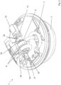
- a dosing system 1 according to the invention is shown with a dosing device 2 and a container 3.
- a dosing unit 4 has a pump 5 which is designed as a peristaltic pump according to the invention.
- the pump 5 is also designed as a double-head pump with a double head 6. This enables separate dosing of two flowable preparations which are stored in different, separate cavities of the container 3.
- a flowable preparation is dispensed into the interior of the washing machine, which is led from the container 3 via an inlet 9 into a pump hose 7.
- a motor 10 of the dosing unit 4 drives the pump 5.
- the motor 10 is protected from harmful external influences by a motor protection housing 12.
- the pump 5 is also protected by a pump protection housing 11.
- the dosing system 1 which preferably has an outer shell (not shown) to protect the container 3 and the dosing device 2, is Users put the detergent into the washing machine's tub together with the laundry to be washed.
- the dosing system 1 has an interface for receiving dosing commands.
- the dosing system 1 can be controlled by the user using a smartphone app.
- Various washing programs and dosages can be set in the app.
- two-way communication is advantageous; for example, the dosing system 1 can have additional sensors that record the exact position of the dosing system 1 in the washing machine, the presence of water and the amount of laundry in the tub and transmit this information. In this way, precise dosing can be achieved depending on the amount of laundry, the flowable preparation, the washing program and the individual treatment step of the washing process.
- FIG 2 shows the dosing system 1 according to Figure 1 in a view without protective housing, so that a sensor unit 15 is visible, which extends over the double head 6.
- a Hall sensor 16 is provided, which detects the rotational position of the rotating body 13 by means of a magnet 14 attached to a rotating body 13.
- the motor 10 is connected to a gear 17 and a bidirectional freewheel 18, which enables a pump shaft 19 to be moved with a change of direction, so that the pump 5 with the double head 6 can meter out two liquid preparations taken from the container 3 individually and separately from one another via the pump hoses 7.
- Figure 3 is a cross-section of the dosing system 1 according to Figure 1 shown.
- the container 3 is detachably coupled to the dosing device 2 in a container holder 20.
- This has the advantage that the container 3 can be exchanged or refilled and reinserted into the dosing system 1.
- a leak-proof connection of the container 3 to the dosing device 2 is ensured.
- the flowable preparation can only escape from the container 3 via the inlet 9 and reach the pump 5 via the pump hose 7 when the pump is driven by the motor 10 and the pump shaft 19 and sucks the flowable preparation out of the container 3.
- the two rotating bodies 13a,b each have magnets 14a,b, which are each detected by the two Hall sensors 16a,b in order to precisely detect the position of the rotating bodies 13a,b when they pass the Hall sensors 16a,b. This ensures a consistently high dosing accuracy for both flowable preparations to be dispensed.
- Figure 4 and 5 each show a cross-section through a pump 5 of the dosing device 2.
- Figure 4 shows a receptacle 22 of the pump 5 for the pump hose 7a of a first flowable preparation with a constant segment radius of pump segments 21a-h.
- the flowable preparation running into the pump hose 7a via the inlet 9a enters the pump 5, in the area of the pump segment 21h it leaves it again. Due to the circular movement of the eccentrically mounted The flowable preparation within the pump hose 7a is pressed through the pump segments 21a-h by the rotating body 13.
- the flowable preparation that enters the pump 5 in the pump segment 21a is sucked out of the container 3 fixed in the container holder 20 and discharged again in the area of the pump segments 21e-h.
- the rotating body 13 alternately loads the pump hose 7a during its rotation. In the areas of compression, it also seals the pump hose 7a against the environment.
- the sensor unit can use the magnet 14 to precisely detect the position of the rotating body 13, which is important for dosing accuracy.
- the pump head which is connected to the inlet 9b of the second flowable preparation via the pump hose 7b, remains stationary. In this way, an accidental dispensing of the second flowable preparation together with the first flowable preparation from the dosing system 1 can be prevented.
- the receptacle of the pump 5 of the dosing device 2 in the pump segments 21e-g has a smaller segment radius than the area of the pump segments 21a-d and 21h, so that a step 23 extends over this area of the wall of the receptacle 22.
- the maximum load on the pump hose 7 occurs in this area. In the other segments, there is less compression and thus less load on the pump hose 7, which extends the service life of the pump hose. In addition, sealing is best ensured in these segments.
- the rotating body 13 can be rotated further by means of the pump shaft 19 after the dosing process has ended until it comes to a standstill in the narrowed area of the receptacle 22 and assumes a valve position there. In this area, the sealing of the dosing system 1 can be best ensured, since the compression of the pump hose 7 is maximized here.
Landscapes
- Engineering & Computer Science (AREA)
- Textile Engineering (AREA)
- Mechanical Engineering (AREA)
- General Engineering & Computer Science (AREA)
- Devices For Dispensing Beverages (AREA)
- Washing And Drying Of Tableware (AREA)
- Feeding, Discharge, Calcimining, Fusing, And Gas-Generation Devices (AREA)
- Detail Structures Of Washing Machines And Dryers (AREA)
Claims (9)
- Système de dosage (1) pour la distribution d'au moins une préparation fluide dans un espace intérieur d'un lave-linge, comprenant- au moins un appareil de dosage (2) qui comprend- au moins une source d'énergie électrique pour faire fonctionner l'appareil de dosage (2),- au moins une unité de dosage (4) pour la distribution d'une quantité prédéfinie de l'au moins une préparation fluide,- au moins une unité formant capteur (15) pour la surveillance de l'unité de dosage (4),- au moins une unité de commande couplée à l'unité de dosage (4) et à l'unité formant capteur (15) et- au moins un récipient (3) pouvant être accouplé à l'appareil de dosage (2) pour le stockage de l'au moins une préparation fluide, dans lequel l'unité de dosage (4) présente une pompe péristaltique (5) pour la distribution de l'au moins une préparation fluide et dans lequel le système de dosage (1) est adapté pour être positionné librement à l'intérieur de l'espace intérieur du lave-linge, caractérisé en ce que la pompe péristaltique (5) comprend un corps rotatif (13) monté de manière excentrée à l'intérieur d'un logement (22) pour le transport de l'au moins une préparation fluide à travers un tuyau de pompage (7).
- Système de dosage (1) selon la revendication 1, caractérisé en ce que le corps rotatif (13) peut être commandé par l'unité de commande au moyen d'au moins un signal transmis par l'unité formant capteur (15).
- Système de dosage (1) selon la revendication 1 ou 2, caractérisé en ce que l'unité formant capteur (15) présente au moins un capteur à effet Hall (16) et le corps rotatif (13) présente au moins un aimant (14).
- Système de dosage (1) selon l'une des revendications 1 à 3,
caractérisé en ce que le corps rotatif (13) peut être déplacé par l'unité de commande dans une position de vanne pour fermer de manière étanche la pompe péristaltique. - Système de dosage (1) selon l'une des revendications 1 à 4,
caractérisé en ce que le logement (22) de la pompe péristaltique est rétréci à certains endroits. - Système de dosage (1) selon l'une des revendications 1 à 5,
caractérisé en ce que le récipient (3) est adapté pour le stockage séparé d'au moins deux préparations fluides. - Système de dosage (1) selon l'une des revendications 1 à 6,
caractérisé en ce que la pompe péristaltique comprend une double tête (6). - Système de dosage (1) selon l'une des revendications 1 à 7,
caractérisé en ce que la pompe péristaltique comprend une roue libre (18) bidirectionnelle. - Système de dosage (1) selon la revendication 1, caractérisé en ce que le système de dosage (1) comprend une enveloppe extérieure conçue sous forme sensiblement sphérique qui est adaptée pour le logement de l'appareil de dosage (2) et du récipient (3).
Priority Applications (8)
| Application Number | Priority Date | Filing Date | Title |
|---|---|---|---|
| EP22157798.4A EP4230785B1 (fr) | 2022-02-21 | 2022-02-21 | Système de dosage destiné à la distribution d'au moins une préparation fluide dans un espace intérieur d'un lave-linge |
| PL22157798.4T PL4230785T3 (pl) | 2022-02-21 | 2022-02-21 | System dozowania do podawania co najmniej jednego płynnego preparatu do komory pralki |
| ES22157798T ES2993537T3 (en) | 2022-02-21 | 2022-02-21 | Dosing system for dispensing at least one flowable preparation into an interior of a washing machine |
| KR1020247027464A KR20240149898A (ko) | 2022-02-21 | 2023-01-20 | 적어도 하나의 유동성 제제를 세탁기의 내부로 분배하기 위한 계량 시스템 |
| PCT/EP2023/051389 WO2023156134A1 (fr) | 2022-02-21 | 2023-01-20 | Système de dosage pour la distribution d'au moins une préparation fluide à l'intérieur d'une machine à laver |
| JP2024549142A JP2025505823A (ja) | 2022-02-21 | 2023-01-20 | 少なくとも1つの流動性製剤を洗濯機の内部に吐出するための計量システム |
| CN202380022469.2A CN118715347A (zh) | 2022-02-21 | 2023-01-20 | 用于将至少一种可流动制剂分配到洗衣机的内部中的计量系统 |
| US18/811,459 US20240410102A1 (en) | 2022-02-21 | 2024-08-21 | Metering System For Dispensing At Least One Flowable Preparation Into An Interior Of A Washing Machine |
Applications Claiming Priority (1)
| Application Number | Priority Date | Filing Date | Title |
|---|---|---|---|
| EP22157798.4A EP4230785B1 (fr) | 2022-02-21 | 2022-02-21 | Système de dosage destiné à la distribution d'au moins une préparation fluide dans un espace intérieur d'un lave-linge |
Publications (2)
| Publication Number | Publication Date |
|---|---|
| EP4230785A1 EP4230785A1 (fr) | 2023-08-23 |
| EP4230785B1 true EP4230785B1 (fr) | 2024-10-09 |
Family
ID=80446163
Family Applications (1)
| Application Number | Title | Priority Date | Filing Date |
|---|---|---|---|
| EP22157798.4A Active EP4230785B1 (fr) | 2022-02-21 | 2022-02-21 | Système de dosage destiné à la distribution d'au moins une préparation fluide dans un espace intérieur d'un lave-linge |
Country Status (8)
| Country | Link |
|---|---|
| US (1) | US20240410102A1 (fr) |
| EP (1) | EP4230785B1 (fr) |
| JP (1) | JP2025505823A (fr) |
| KR (1) | KR20240149898A (fr) |
| CN (1) | CN118715347A (fr) |
| ES (1) | ES2993537T3 (fr) |
| PL (1) | PL4230785T3 (fr) |
| WO (1) | WO2023156134A1 (fr) |
Citations (4)
| Publication number | Priority date | Publication date | Assignee | Title |
|---|---|---|---|---|
| JP5419105B2 (ja) | 2011-03-14 | 2014-02-19 | 株式会社アクアテック | チューブポンプ |
| US20210032793A1 (en) | 2018-03-07 | 2021-02-04 | Henkel Ag & Co. Kgaa | Apparatus with a discharge module and sensor module |
| US20210189631A1 (en) | 2019-12-19 | 2021-06-24 | Henkel Ag & Co. Kgaa | Method and device for dispensing a fragrance composition during a cleaning cycle of a household appliance |
| US20220034020A1 (en) | 2018-11-15 | 2022-02-03 | Lg Electronics Inc. | Washing machine |
Family Cites Families (13)
| Publication number | Priority date | Publication date | Assignee | Title |
|---|---|---|---|---|
| SE441855B (sv) * | 1984-03-30 | 1985-11-11 | Sala International Ab | Peristaltisk pump |
| US4856972A (en) * | 1988-06-09 | 1989-08-15 | Fisher Scientific Co. | Dual roller peristaltic pump |
| US20070000068A1 (en) * | 2005-06-30 | 2007-01-04 | Gerard France Paul Amaat R | Fabric article treating device and system |
| DE102007014425A1 (de) * | 2007-03-22 | 2008-09-25 | Henkel Ag & Co. Kgaa | Bewegliches Dosiersystem zur Abgabe von fließ- oder streufähigen Zubereitungen |
| DE102010027991A1 (de) * | 2010-04-20 | 2011-10-20 | Henkel Ag & Co. Kgaa | Dosiersystem zur Verwendung in Verbindung mit einem wasserführenden Haushaltsgerät wie eine Waschmaschine, Spülmaschine, Wäschetrockner oder dergleichen |
| DE102010027994A1 (de) * | 2010-04-20 | 2011-10-20 | Henkel Ag & Co. Kgaa | Dosiersystem zur Freisetzung von wenigstens drei unterschiedlichen Zubereitungen während eines Waschprogramms einer Waschmaschine |
| DE102010028354A1 (de) | 2010-04-29 | 2011-12-29 | Henkel Ag & Co. Kgaa | Dosiersystem zur Verwendung in Verbindung mit einem wasserführenden Haushaltsgerät wie eine Waschmaschine, Spülmaschine, Wäschetrockner oder dergleichen |
| DE102013104242A1 (de) * | 2013-04-26 | 2014-10-30 | Emitec Gesellschaft Für Emissionstechnologie Mbh | Vorrichtung zur dosierten Bereitstellung einer Flüssigkeit |
| DE102015207342B4 (de) * | 2015-04-22 | 2021-09-23 | BSH Hausgeräte GmbH | Wäschepflegegerät mit einem Dosiersystem |
| WO2017167658A1 (fr) | 2016-03-30 | 2017-10-05 | Unilever Plc | Dispositif et procédé de communication pour blanchisserie |
| CN106758013A (zh) * | 2016-12-27 | 2017-05-31 | 珠海格力电器股份有限公司 | 一种洗涤剂检测投放装置 |
| WO2023201187A1 (fr) * | 2022-04-11 | 2023-10-19 | Basf Corporation | Système de distribution de liquide pour un dispositif de traitement de semences |
| DE102023201351B3 (de) * | 2023-02-16 | 2024-03-21 | E.G.O. Elektro-Gerätebau GmbH | Mischvorrichtung zum Durchmischen eines Zusatzstoffes mit einer Flüssigkeit in einer Waschmaschine, Waschmaschine und Verfahren |
-
2022
- 2022-02-21 EP EP22157798.4A patent/EP4230785B1/fr active Active
- 2022-02-21 PL PL22157798.4T patent/PL4230785T3/pl unknown
- 2022-02-21 ES ES22157798T patent/ES2993537T3/es active Active
-
2023
- 2023-01-20 JP JP2024549142A patent/JP2025505823A/ja active Pending
- 2023-01-20 CN CN202380022469.2A patent/CN118715347A/zh active Pending
- 2023-01-20 WO PCT/EP2023/051389 patent/WO2023156134A1/fr not_active Ceased
- 2023-01-20 KR KR1020247027464A patent/KR20240149898A/ko active Pending
-
2024
- 2024-08-21 US US18/811,459 patent/US20240410102A1/en active Pending
Patent Citations (4)
| Publication number | Priority date | Publication date | Assignee | Title |
|---|---|---|---|---|
| JP5419105B2 (ja) | 2011-03-14 | 2014-02-19 | 株式会社アクアテック | チューブポンプ |
| US20210032793A1 (en) | 2018-03-07 | 2021-02-04 | Henkel Ag & Co. Kgaa | Apparatus with a discharge module and sensor module |
| US20220034020A1 (en) | 2018-11-15 | 2022-02-03 | Lg Electronics Inc. | Washing machine |
| US20210189631A1 (en) | 2019-12-19 | 2021-06-24 | Henkel Ag & Co. Kgaa | Method and device for dispensing a fragrance composition during a cleaning cycle of a household appliance |
Non-Patent Citations (3)
| Title |
|---|
| ANONYMOUS: "About Ring Pump", AQUATECH CO., LTD, 1 January 2025 (2025-01-01), XP093298725 |
| ANONYMOUS: "Mechanism of the Peristaltic Pump", TFS (TAKASAGO FLUIDIC SYSTEMS), 31 March 2020 (2020-03-31), XP093298730, Retrieved from the Internet <URL:https://www.takasago-fluidics.com/blogs/technical-information/mechanism-of-peristaltic-pump> |
| MCCARTHY DAVID T., SHI BAIQIAN, WANG MIAO, CATSAMAS STEPHEN: "BoSL FAL pump: A small, low-cost, easily constructed, 3D-printed peristaltic pump for sampling of waters", HARDWAREX, ELSEVIER LTD, vol. 10, 1 October 2021 (2021-10-01), pages e00214, XP093298722, ISSN: 2468-0672, DOI: 10.1016/j.ohx.2021.e00214 |
Also Published As
| Publication number | Publication date |
|---|---|
| US20240410102A1 (en) | 2024-12-12 |
| ES2993537T3 (en) | 2025-01-02 |
| PL4230785T3 (pl) | 2025-02-24 |
| CN118715347A (zh) | 2024-09-27 |
| JP2025505823A (ja) | 2025-02-28 |
| KR20240149898A (ko) | 2024-10-15 |
| WO2023156134A1 (fr) | 2023-08-24 |
| EP4230785A1 (fr) | 2023-08-23 |
Similar Documents
| Publication | Publication Date | Title |
|---|---|---|
| DE60123086T2 (de) | Schlauchpumpe | |
| DE69731464T2 (de) | Ambulante, mikroprozessorgesteuerte volumetrische einwegpumpe | |
| EP3074632B1 (fr) | Pompe à liquides entraînée par un moteur électrique, en particulier pour la lubrification forcée de la boîte de vitesses de véhicules automobiles | |
| EP2747619B1 (fr) | Doseur de nettoyage | |
| DE69629323T2 (de) | Permanentmagnetisch erregter Synchronmotor | |
| EP1209275B1 (fr) | Dispositif pour l' évacuation de l'eau de lavage dans une machine à laver | |
| DE69303516T2 (de) | Lineare Peristaltikpumpe | |
| DE2933513A1 (de) | Waeschetrockner mit kondensationseinrichtung | |
| DE102020207431A1 (de) | Elektrische Maschine mit Rotorkühlung | |
| EP4230785B1 (fr) | Système de dosage destiné à la distribution d'au moins une préparation fluide dans un espace intérieur d'un lave-linge | |
| DE102011111180A1 (de) | Zusatzstoffdosierer | |
| DE2352677C2 (de) | Vorrichtung zum Dosieren von Chemikalienlösungen | |
| EP3175752B1 (fr) | Robot ménager et dispositif de verrouillage | |
| EP3669718A1 (fr) | Dispositif de réservoir d'eau et distributeur automatique de boissons | |
| DE102004048556A1 (de) | Laugenbehälter für eine Waschmaschine | |
| DE202013100271U1 (de) | Durchflussmesseinrichtung für eine Getränkezubereitungsmaschine | |
| DE3940730A1 (de) | Peristaltische schlauchpumpe zum foerdern eines fluids | |
| WO2025149277A1 (fr) | Pompe à lubrifiant | |
| CH617974A5 (en) | Washing machine | |
| DE19923932A1 (de) | Flüssigkeitszähler mit multifunktionalem Meßkammerdeckel | |
| DE202004021615U9 (de) | Automatische Dosiervorrichtung mit Motorauflaufdämpfungsmitteln | |
| DE102022134552B4 (de) | Haushaltsgerät | |
| DE20320332U1 (de) | Elektronischer Fluidspender | |
| EP0978709A2 (fr) | Dispositif de mesure de débit d'un liquide | |
| DE102006005770A1 (de) | Wäschebehandlungsmaschine mit Sicherheitseinrichtung |
Legal Events
| Date | Code | Title | Description |
|---|---|---|---|
| PUAI | Public reference made under article 153(3) epc to a published international application that has entered the european phase |
Free format text: ORIGINAL CODE: 0009012 |
|
| STAA | Information on the status of an ep patent application or granted ep patent |
Free format text: STATUS: THE APPLICATION HAS BEEN PUBLISHED |
|
| AK | Designated contracting states |
Kind code of ref document: A1 Designated state(s): AL AT BE BG CH CY CZ DE DK EE ES FI FR GB GR HR HU IE IS IT LI LT LU LV MC MK MT NL NO PL PT RO RS SE SI SK SM TR |
|
| STAA | Information on the status of an ep patent application or granted ep patent |
Free format text: STATUS: REQUEST FOR EXAMINATION WAS MADE |
|
| 17P | Request for examination filed |
Effective date: 20240221 |
|
| RBV | Designated contracting states (corrected) |
Designated state(s): AL AT BE BG CH CY CZ DE DK EE ES FI FR GB GR HR HU IE IS IT LI LT LU LV MC MK MT NL NO PL PT RO RS SE SI SK SM TR |
|
| GRAP | Despatch of communication of intention to grant a patent |
Free format text: ORIGINAL CODE: EPIDOSNIGR1 |
|
| STAA | Information on the status of an ep patent application or granted ep patent |
Free format text: STATUS: GRANT OF PATENT IS INTENDED |
|
| RIC1 | Information provided on ipc code assigned before grant |
Ipc: D06F 34/14 20200101ALN20240429BHEP Ipc: D06F 33/37 20200101ALN20240429BHEP Ipc: D06F 39/02 20060101AFI20240429BHEP |
|
| INTG | Intention to grant announced |
Effective date: 20240515 |
|
| GRAS | Grant fee paid |
Free format text: ORIGINAL CODE: EPIDOSNIGR3 |
|
| GRAA | (expected) grant |
Free format text: ORIGINAL CODE: 0009210 |
|
| STAA | Information on the status of an ep patent application or granted ep patent |
Free format text: STATUS: THE PATENT HAS BEEN GRANTED |
|
| AK | Designated contracting states |
Kind code of ref document: B1 Designated state(s): AL AT BE BG CH CY CZ DE DK EE ES FI FR GB GR HR HU IE IS IT LI LT LU LV MC MK MT NL NO PL PT RO RS SE SI SK SM TR |
|
| REG | Reference to a national code |
Ref country code: CH Ref legal event code: EP |
|
| REG | Reference to a national code |
Ref country code: DE Ref legal event code: R096 Ref document number: 502022001823 Country of ref document: DE |
|
| REG | Reference to a national code |
Ref country code: IE Ref legal event code: FG4D Free format text: LANGUAGE OF EP DOCUMENT: GERMAN |
|
| P01 | Opt-out of the competence of the unified patent court (upc) registered |
Free format text: CASE NUMBER: APP_55000/2024 Effective date: 20241007 |
|
| REG | Reference to a national code |
Ref country code: ES Ref legal event code: FG2A Ref document number: 2993537 Country of ref document: ES Kind code of ref document: T3 Effective date: 20250102 |
|
| REG | Reference to a national code |
Ref country code: LT Ref legal event code: MG9D |
|
| REG | Reference to a national code |
Ref country code: NL Ref legal event code: MP Effective date: 20241009 |
|
| PG25 | Lapsed in a contracting state [announced via postgrant information from national office to epo] |
Ref country code: NL Free format text: LAPSE BECAUSE OF FAILURE TO SUBMIT A TRANSLATION OF THE DESCRIPTION OR TO PAY THE FEE WITHIN THE PRESCRIBED TIME-LIMIT Effective date: 20241009 |
|
| PG25 | Lapsed in a contracting state [announced via postgrant information from national office to epo] |
Ref country code: NL Free format text: LAPSE BECAUSE OF FAILURE TO SUBMIT A TRANSLATION OF THE DESCRIPTION OR TO PAY THE FEE WITHIN THE PRESCRIBED TIME-LIMIT Effective date: 20241009 |
|
| PG25 | Lapsed in a contracting state [announced via postgrant information from national office to epo] |
Ref country code: PT Free format text: LAPSE BECAUSE OF FAILURE TO SUBMIT A TRANSLATION OF THE DESCRIPTION OR TO PAY THE FEE WITHIN THE PRESCRIBED TIME-LIMIT Effective date: 20250210 Ref country code: HR Free format text: LAPSE BECAUSE OF FAILURE TO SUBMIT A TRANSLATION OF THE DESCRIPTION OR TO PAY THE FEE WITHIN THE PRESCRIBED TIME-LIMIT Effective date: 20241009 Ref country code: IS Free format text: LAPSE BECAUSE OF FAILURE TO SUBMIT A TRANSLATION OF THE DESCRIPTION OR TO PAY THE FEE WITHIN THE PRESCRIBED TIME-LIMIT Effective date: 20250209 |
|
| PG25 | Lapsed in a contracting state [announced via postgrant information from national office to epo] |
Ref country code: FI Free format text: LAPSE BECAUSE OF FAILURE TO SUBMIT A TRANSLATION OF THE DESCRIPTION OR TO PAY THE FEE WITHIN THE PRESCRIBED TIME-LIMIT Effective date: 20241009 |
|
| PG25 | Lapsed in a contracting state [announced via postgrant information from national office to epo] |
Ref country code: BG Free format text: LAPSE BECAUSE OF FAILURE TO SUBMIT A TRANSLATION OF THE DESCRIPTION OR TO PAY THE FEE WITHIN THE PRESCRIBED TIME-LIMIT Effective date: 20241009 |
|
| PG25 | Lapsed in a contracting state [announced via postgrant information from national office to epo] |
Ref country code: NO Free format text: LAPSE BECAUSE OF FAILURE TO SUBMIT A TRANSLATION OF THE DESCRIPTION OR TO PAY THE FEE WITHIN THE PRESCRIBED TIME-LIMIT Effective date: 20250109 |
|
| PG25 | Lapsed in a contracting state [announced via postgrant information from national office to epo] |
Ref country code: LV Free format text: LAPSE BECAUSE OF FAILURE TO SUBMIT A TRANSLATION OF THE DESCRIPTION OR TO PAY THE FEE WITHIN THE PRESCRIBED TIME-LIMIT Effective date: 20241009 Ref country code: GR Free format text: LAPSE BECAUSE OF FAILURE TO SUBMIT A TRANSLATION OF THE DESCRIPTION OR TO PAY THE FEE WITHIN THE PRESCRIBED TIME-LIMIT Effective date: 20250110 |
|
| PG25 | Lapsed in a contracting state [announced via postgrant information from national office to epo] |
Ref country code: RS Free format text: LAPSE BECAUSE OF FAILURE TO SUBMIT A TRANSLATION OF THE DESCRIPTION OR TO PAY THE FEE WITHIN THE PRESCRIBED TIME-LIMIT Effective date: 20250109 |
|
| PG25 | Lapsed in a contracting state [announced via postgrant information from national office to epo] |
Ref country code: SM Free format text: LAPSE BECAUSE OF FAILURE TO SUBMIT A TRANSLATION OF THE DESCRIPTION OR TO PAY THE FEE WITHIN THE PRESCRIBED TIME-LIMIT Effective date: 20241009 |
|
| REG | Reference to a national code |
Ref country code: DE Ref legal event code: R026 Ref document number: 502022001823 Country of ref document: DE |
|
| PG25 | Lapsed in a contracting state [announced via postgrant information from national office to epo] |
Ref country code: DK Free format text: LAPSE BECAUSE OF FAILURE TO SUBMIT A TRANSLATION OF THE DESCRIPTION OR TO PAY THE FEE WITHIN THE PRESCRIBED TIME-LIMIT Effective date: 20241009 |
|
| PGFP | Annual fee paid to national office [announced via postgrant information from national office to epo] |
Ref country code: ES Payment date: 20250331 Year of fee payment: 4 |
|
| PG25 | Lapsed in a contracting state [announced via postgrant information from national office to epo] |
Ref country code: EE Free format text: LAPSE BECAUSE OF FAILURE TO SUBMIT A TRANSLATION OF THE DESCRIPTION OR TO PAY THE FEE WITHIN THE PRESCRIBED TIME-LIMIT Effective date: 20241009 |
|
| PLBI | Opposition filed |
Free format text: ORIGINAL CODE: 0009260 |
|
| PLAX | Notice of opposition and request to file observation + time limit sent |
Free format text: ORIGINAL CODE: EPIDOSNOBS2 |
|
| PG25 | Lapsed in a contracting state [announced via postgrant information from national office to epo] |
Ref country code: RO Free format text: LAPSE BECAUSE OF FAILURE TO SUBMIT A TRANSLATION OF THE DESCRIPTION OR TO PAY THE FEE WITHIN THE PRESCRIBED TIME-LIMIT Effective date: 20241009 |
|
| PG25 | Lapsed in a contracting state [announced via postgrant information from national office to epo] |
Ref country code: SK Free format text: LAPSE BECAUSE OF FAILURE TO SUBMIT A TRANSLATION OF THE DESCRIPTION OR TO PAY THE FEE WITHIN THE PRESCRIBED TIME-LIMIT Effective date: 20241009 |
|
| PG25 | Lapsed in a contracting state [announced via postgrant information from national office to epo] |
Ref country code: CZ Free format text: LAPSE BECAUSE OF FAILURE TO SUBMIT A TRANSLATION OF THE DESCRIPTION OR TO PAY THE FEE WITHIN THE PRESCRIBED TIME-LIMIT Effective date: 20241009 |
|
| 26 | Opposition filed |
Opponent name: THE PROCTER & GAMBLE COMPANY Effective date: 20250709 |
|
| PG25 | Lapsed in a contracting state [announced via postgrant information from national office to epo] |
Ref country code: SE Free format text: LAPSE BECAUSE OF FAILURE TO SUBMIT A TRANSLATION OF THE DESCRIPTION OR TO PAY THE FEE WITHIN THE PRESCRIBED TIME-LIMIT Effective date: 20241009 |
|
| PG25 | Lapsed in a contracting state [announced via postgrant information from national office to epo] |
Ref country code: MC Free format text: LAPSE BECAUSE OF FAILURE TO SUBMIT A TRANSLATION OF THE DESCRIPTION OR TO PAY THE FEE WITHIN THE PRESCRIBED TIME-LIMIT Effective date: 20241009 |
|
| REG | Reference to a national code |
Ref country code: CH Ref legal event code: PL |
|
| PG25 | Lapsed in a contracting state [announced via postgrant information from national office to epo] |
Ref country code: LU Free format text: LAPSE BECAUSE OF NON-PAYMENT OF DUE FEES Effective date: 20250221 |
|
| PG25 | Lapsed in a contracting state [announced via postgrant information from national office to epo] |
Ref country code: CH Free format text: LAPSE BECAUSE OF NON-PAYMENT OF DUE FEES Effective date: 20250228 |
|
| PLBB | Reply of patent proprietor to notice(s) of opposition received |
Free format text: ORIGINAL CODE: EPIDOSNOBS3 |
|
| REG | Reference to a national code |
Ref country code: BE Ref legal event code: MM Effective date: 20250228 |
|
| PG25 | Lapsed in a contracting state [announced via postgrant information from national office to epo] |
Ref country code: BE Free format text: LAPSE BECAUSE OF NON-PAYMENT OF DUE FEES Effective date: 20250228 |
|
| PG25 | Lapsed in a contracting state [announced via postgrant information from national office to epo] |
Ref country code: IE Free format text: LAPSE BECAUSE OF NON-PAYMENT OF DUE FEES Effective date: 20250221 |
|
| PGFP | Annual fee paid to national office [announced via postgrant information from national office to epo] |
Ref country code: GB Payment date: 20260220 Year of fee payment: 5 |
|
| PGFP | Annual fee paid to national office [announced via postgrant information from national office to epo] |
Ref country code: DE Payment date: 20260218 Year of fee payment: 5 |
|
| PGFP | Annual fee paid to national office [announced via postgrant information from national office to epo] |
Ref country code: AT Payment date: 20260301 Year of fee payment: 5 |
|
| PGFP | Annual fee paid to national office [announced via postgrant information from national office to epo] |
Ref country code: IT Payment date: 20260224 Year of fee payment: 5 |
|
| PGFP | Annual fee paid to national office [announced via postgrant information from national office to epo] |
Ref country code: FR Payment date: 20260219 Year of fee payment: 5 |
|
| PGFP | Annual fee paid to national office [announced via postgrant information from national office to epo] |
Ref country code: PL Payment date: 20260212 Year of fee payment: 5 |