EP4230877A1 - Elektromagnetisch angetriebene aktuatorsysteme - Google Patents
Elektromagnetisch angetriebene aktuatorsysteme Download PDFInfo
- Publication number
- EP4230877A1 EP4230877A1 EP23157271.0A EP23157271A EP4230877A1 EP 4230877 A1 EP4230877 A1 EP 4230877A1 EP 23157271 A EP23157271 A EP 23157271A EP 4230877 A1 EP4230877 A1 EP 4230877A1
- Authority
- EP
- European Patent Office
- Prior art keywords
- solenoid
- pressure
- transfer
- low
- actuator
- Prior art date
- Legal status (The legal status is an assumption and is not a legal conclusion. Google has not performed a legal analysis and makes no representation as to the accuracy of the status listed.)
- Granted
Links
Images

Classifications
-
- F—MECHANICAL ENGINEERING; LIGHTING; HEATING; WEAPONS; BLASTING
- F16—ENGINEERING ELEMENTS AND UNITS; GENERAL MEASURES FOR PRODUCING AND MAINTAINING EFFECTIVE FUNCTIONING OF MACHINES OR INSTALLATIONS; THERMAL INSULATION IN GENERAL
- F16K—VALVES; TAPS; COCKS; ACTUATING-FLOATS; DEVICES FOR VENTING OR AERATING
- F16K31/00—Actuating devices; Operating means; Releasing devices
- F16K31/02—Actuating devices; Operating means; Releasing devices electric; magnetic
- F16K31/06—Actuating devices; Operating means; Releasing devices electric; magnetic using a magnet, e.g. diaphragm valves, cutting off by means of a liquid
- F16K31/0603—Multiple-way valves
-
- F—MECHANICAL ENGINEERING; LIGHTING; HEATING; WEAPONS; BLASTING
- F15—FLUID-PRESSURE ACTUATORS; HYDRAULICS OR PNEUMATICS IN GENERAL
- F15B—SYSTEMS ACTING BY MEANS OF FLUIDS IN GENERAL; FLUID-PRESSURE ACTUATORS, e.g. SERVOMOTORS; DETAILS OF FLUID-PRESSURE SYSTEMS, NOT OTHERWISE PROVIDED FOR
- F15B20/00—Safety arrangements for fluid actuator systems; Applications of safety devices in fluid actuator systems; Emergency measures for fluid actuator systems
- F15B20/002—Electrical failure
-
- F—MECHANICAL ENGINEERING; LIGHTING; HEATING; WEAPONS; BLASTING
- F01—MACHINES OR ENGINES IN GENERAL; ENGINE PLANTS IN GENERAL; STEAM ENGINES
- F01D—NON-POSITIVE DISPLACEMENT MACHINES OR ENGINES, e.g. STEAM TURBINES
- F01D17/00—Regulating or controlling by varying flow
- F01D17/20—Devices dealing with sensing elements or final actuators or transmitting means between them, e.g. power-assisted
-
- F—MECHANICAL ENGINEERING; LIGHTING; HEATING; WEAPONS; BLASTING
- F15—FLUID-PRESSURE ACTUATORS; HYDRAULICS OR PNEUMATICS IN GENERAL
- F15B—SYSTEMS ACTING BY MEANS OF FLUIDS IN GENERAL; FLUID-PRESSURE ACTUATORS, e.g. SERVOMOTORS; DETAILS OF FLUID-PRESSURE SYSTEMS, NOT OTHERWISE PROVIDED FOR
- F15B13/00—Details of servomotor systems ; Valves for servomotor systems
- F15B13/02—Fluid distribution or supply devices characterised by their adaptation to the control of servomotors
- F15B13/04—Fluid distribution or supply devices characterised by their adaptation to the control of servomotors for use with a single servomotor
- F15B13/044—Fluid distribution or supply devices characterised by their adaptation to the control of servomotors for use with a single servomotor operated by electrically-controlled means, e.g. solenoids, torque-motors
-
- F—MECHANICAL ENGINEERING; LIGHTING; HEATING; WEAPONS; BLASTING
- F15—FLUID-PRESSURE ACTUATORS; HYDRAULICS OR PNEUMATICS IN GENERAL
- F15B—SYSTEMS ACTING BY MEANS OF FLUIDS IN GENERAL; FLUID-PRESSURE ACTUATORS, e.g. SERVOMOTORS; DETAILS OF FLUID-PRESSURE SYSTEMS, NOT OTHERWISE PROVIDED FOR
- F15B20/00—Safety arrangements for fluid actuator systems; Applications of safety devices in fluid actuator systems; Emergency measures for fluid actuator systems
- F15B20/008—Valve failure
-
- F—MECHANICAL ENGINEERING; LIGHTING; HEATING; WEAPONS; BLASTING
- F16—ENGINEERING ELEMENTS AND UNITS; GENERAL MEASURES FOR PRODUCING AND MAINTAINING EFFECTIVE FUNCTIONING OF MACHINES OR INSTALLATIONS; THERMAL INSULATION IN GENERAL
- F16K—VALVES; TAPS; COCKS; ACTUATING-FLOATS; DEVICES FOR VENTING OR AERATING
- F16K11/00—Multiple-way valves, e.g. mixing valves; Pipe fittings incorporating such valves
- F16K11/02—Multiple-way valves, e.g. mixing valves; Pipe fittings incorporating such valves with all movable sealing faces moving as one unit
-
- F—MECHANICAL ENGINEERING; LIGHTING; HEATING; WEAPONS; BLASTING
- F16—ENGINEERING ELEMENTS AND UNITS; GENERAL MEASURES FOR PRODUCING AND MAINTAINING EFFECTIVE FUNCTIONING OF MACHINES OR INSTALLATIONS; THERMAL INSULATION IN GENERAL
- F16K—VALVES; TAPS; COCKS; ACTUATING-FLOATS; DEVICES FOR VENTING OR AERATING
- F16K31/00—Actuating devices; Operating means; Releasing devices
- F16K31/02—Actuating devices; Operating means; Releasing devices electric; magnetic
- F16K31/06—Actuating devices; Operating means; Releasing devices electric; magnetic using a magnet, e.g. diaphragm valves, cutting off by means of a liquid
- F16K31/0603—Multiple-way valves
- F16K31/0606—Multiple-way valves fluid passing through the solenoid coil
-
- F—MECHANICAL ENGINEERING; LIGHTING; HEATING; WEAPONS; BLASTING
- F05—INDEXING SCHEMES RELATING TO ENGINES OR PUMPS IN VARIOUS SUBCLASSES OF CLASSES F01-F04
- F05D—INDEXING SCHEME FOR ASPECTS RELATING TO NON-POSITIVE-DISPLACEMENT MACHINES OR ENGINES, GAS-TURBINES OR JET-PROPULSION PLANTS
- F05D2220/00—Application
- F05D2220/30—Application in turbines
- F05D2220/32—Application in turbines in gas turbines
-
- F—MECHANICAL ENGINEERING; LIGHTING; HEATING; WEAPONS; BLASTING
- F05—INDEXING SCHEMES RELATING TO ENGINES OR PUMPS IN VARIOUS SUBCLASSES OF CLASSES F01-F04
- F05D—INDEXING SCHEME FOR ASPECTS RELATING TO NON-POSITIVE-DISPLACEMENT MACHINES OR ENGINES, GAS-TURBINES OR JET-PROPULSION PLANTS
- F05D2260/00—Function
- F05D2260/60—Fluid transfer
-
- F—MECHANICAL ENGINEERING; LIGHTING; HEATING; WEAPONS; BLASTING
- F05—INDEXING SCHEMES RELATING TO ENGINES OR PUMPS IN VARIOUS SUBCLASSES OF CLASSES F01-F04
- F05D—INDEXING SCHEME FOR ASPECTS RELATING TO NON-POSITIVE-DISPLACEMENT MACHINES OR ENGINES, GAS-TURBINES OR JET-PROPULSION PLANTS
- F05D2260/00—Function
- F05D2260/70—Adjusting of angle of incidence or attack of rotating blades
- F05D2260/79—Bearing, support or actuation arrangements therefor
-
- F—MECHANICAL ENGINEERING; LIGHTING; HEATING; WEAPONS; BLASTING
- F05—INDEXING SCHEMES RELATING TO ENGINES OR PUMPS IN VARIOUS SUBCLASSES OF CLASSES F01-F04
- F05D—INDEXING SCHEME FOR ASPECTS RELATING TO NON-POSITIVE-DISPLACEMENT MACHINES OR ENGINES, GAS-TURBINES OR JET-PROPULSION PLANTS
- F05D2270/00—Control
- F05D2270/60—Control system actuates means
-
- F—MECHANICAL ENGINEERING; LIGHTING; HEATING; WEAPONS; BLASTING
- F05—INDEXING SCHEMES RELATING TO ENGINES OR PUMPS IN VARIOUS SUBCLASSES OF CLASSES F01-F04
- F05D—INDEXING SCHEME FOR ASPECTS RELATING TO NON-POSITIVE-DISPLACEMENT MACHINES OR ENGINES, GAS-TURBINES OR JET-PROPULSION PLANTS
- F05D2270/00—Control
- F05D2270/60—Control system actuates means
- F05D2270/64—Hydraulic actuators
-
- F—MECHANICAL ENGINEERING; LIGHTING; HEATING; WEAPONS; BLASTING
- F15—FLUID-PRESSURE ACTUATORS; HYDRAULICS OR PNEUMATICS IN GENERAL
- F15B—SYSTEMS ACTING BY MEANS OF FLUIDS IN GENERAL; FLUID-PRESSURE ACTUATORS, e.g. SERVOMOTORS; DETAILS OF FLUID-PRESSURE SYSTEMS, NOT OTHERWISE PROVIDED FOR
- F15B2211/00—Circuits for servomotor systems
- F15B2211/30—Directional control
- F15B2211/305—Directional control characterised by the type of valves
- F15B2211/3056—Assemblies of multiple valves
- F15B2211/30565—Assemblies of multiple valves having multiple valves for a single output member, e.g. for creating higher valve function by use of multiple valves like two 2/2-valves replacing a 5/3-valve
-
- F—MECHANICAL ENGINEERING; LIGHTING; HEATING; WEAPONS; BLASTING
- F15—FLUID-PRESSURE ACTUATORS; HYDRAULICS OR PNEUMATICS IN GENERAL
- F15B—SYSTEMS ACTING BY MEANS OF FLUIDS IN GENERAL; FLUID-PRESSURE ACTUATORS, e.g. SERVOMOTORS; DETAILS OF FLUID-PRESSURE SYSTEMS, NOT OTHERWISE PROVIDED FOR
- F15B2211/00—Circuits for servomotor systems
- F15B2211/30—Directional control
- F15B2211/31—Directional control characterised by the positions of the valve element
- F15B2211/3138—Directional control characterised by the positions of the valve element the positions being discrete
-
- F—MECHANICAL ENGINEERING; LIGHTING; HEATING; WEAPONS; BLASTING
- F15—FLUID-PRESSURE ACTUATORS; HYDRAULICS OR PNEUMATICS IN GENERAL
- F15B—SYSTEMS ACTING BY MEANS OF FLUIDS IN GENERAL; FLUID-PRESSURE ACTUATORS, e.g. SERVOMOTORS; DETAILS OF FLUID-PRESSURE SYSTEMS, NOT OTHERWISE PROVIDED FOR
- F15B2211/00—Circuits for servomotor systems
- F15B2211/30—Directional control
- F15B2211/32—Directional control characterised by the type of actuation
- F15B2211/327—Directional control characterised by the type of actuation electrically or electronically
-
- F—MECHANICAL ENGINEERING; LIGHTING; HEATING; WEAPONS; BLASTING
- F15—FLUID-PRESSURE ACTUATORS; HYDRAULICS OR PNEUMATICS IN GENERAL
- F15B—SYSTEMS ACTING BY MEANS OF FLUIDS IN GENERAL; FLUID-PRESSURE ACTUATORS, e.g. SERVOMOTORS; DETAILS OF FLUID-PRESSURE SYSTEMS, NOT OTHERWISE PROVIDED FOR
- F15B2211/00—Circuits for servomotor systems
- F15B2211/70—Output members, e.g. hydraulic motors or cylinders or control therefor
- F15B2211/705—Output members, e.g. hydraulic motors or cylinders or control therefor characterised by the type of output members or actuators
- F15B2211/7051—Linear output members
- F15B2211/7052—Single-acting output members
-
- F—MECHANICAL ENGINEERING; LIGHTING; HEATING; WEAPONS; BLASTING
- F15—FLUID-PRESSURE ACTUATORS; HYDRAULICS OR PNEUMATICS IN GENERAL
- F15B—SYSTEMS ACTING BY MEANS OF FLUIDS IN GENERAL; FLUID-PRESSURE ACTUATORS, e.g. SERVOMOTORS; DETAILS OF FLUID-PRESSURE SYSTEMS, NOT OTHERWISE PROVIDED FOR
- F15B2211/00—Circuits for servomotor systems
- F15B2211/80—Other types of control related to particular problems or conditions
- F15B2211/86—Control during or prevention of abnormal conditions
- F15B2211/862—Control during or prevention of abnormal conditions the abnormal condition being electric or electronic failure
- F15B2211/8623—Electric supply failure
-
- F—MECHANICAL ENGINEERING; LIGHTING; HEATING; WEAPONS; BLASTING
- F15—FLUID-PRESSURE ACTUATORS; HYDRAULICS OR PNEUMATICS IN GENERAL
- F15B—SYSTEMS ACTING BY MEANS OF FLUIDS IN GENERAL; FLUID-PRESSURE ACTUATORS, e.g. SERVOMOTORS; DETAILS OF FLUID-PRESSURE SYSTEMS, NOT OTHERWISE PROVIDED FOR
- F15B2211/00—Circuits for servomotor systems
- F15B2211/80—Other types of control related to particular problems or conditions
- F15B2211/875—Control measures for coping with failures
- F15B2211/8752—Emergency operation mode, e.g. fail-safe operation mode
-
- F—MECHANICAL ENGINEERING; LIGHTING; HEATING; WEAPONS; BLASTING
- F15—FLUID-PRESSURE ACTUATORS; HYDRAULICS OR PNEUMATICS IN GENERAL
- F15B—SYSTEMS ACTING BY MEANS OF FLUIDS IN GENERAL; FLUID-PRESSURE ACTUATORS, e.g. SERVOMOTORS; DETAILS OF FLUID-PRESSURE SYSTEMS, NOT OTHERWISE PROVIDED FOR
- F15B2211/00—Circuits for servomotor systems
- F15B2211/80—Other types of control related to particular problems or conditions
- F15B2211/875—Control measures for coping with failures
- F15B2211/8757—Control measures for coping with failures using redundant components or assemblies
Definitions
- the present disclosure relates to actuator systems and more particularly to solenoid driven actuator systems.
- effector actuation systems (vanes angle, nozzle area, etc) are usually modulated, but sometimes a two-position system may be advantageous.
- weight and space are more critical than previous engines because of the increased externals content added to improve engine efficiency.
- a traditional modulating actuator system usually has two Electro-Hydraulic Servo Valves (EHSVs) and a solenoid driven transfer valve, which tend to be heavy.
- a solenoid driven actuator system includes a first solenoid having at least one pressure input and a pressure outlet downstream from the at least one pressure input.
- a second solenoid has at least one pressure input and a pressure outlet downstream from the at least one pressure input.
- a transfer solenoid operatively coupled to the first and second solenoids.
- An actuator valve operatively coupled to a pressure outlet of the transfer solenoid.
- the at least one pressure input of the first solenoid includes a first pressure input and a second pressure input.
- the at least one pressure input of the second solenoid can include a first pressure input and a second pressure input.
- the transfer solenoid can be in fluid communication with the pressure outlet of the first solenoid and the pressure outlet of the second solenoid.
- a first pressure inlet of the transfer solenoid can be in fluid communication with the pressure outlet of the first solenoid.
- a second pressure inlet of the transfer solenoid can be in fluid communication with the pressure outlet of the second solenoid.
- first and second solenoids are configured and adapted to be operated on a single common channel.
- the first and second solenoids can be configured and adapted to be operated on separate channels.
- the transfer solenoid can be configured and adapted to operate on a transfer solenoid channel separate from channels controlling the first and second solenoids.
- the first solenoid can include a low-pressure conduit.
- the low-pressure conduit can include an orifice.
- the second solenoid can include a low-pressure conduit.
- the low-pressure conduit can include an orifice.
- the first and second solenoids each can include a low-pressure conduit and a low-pressure conduit.
- the low-pressure conduit of the first solenoid can include an orifice and the high-pressure conduit of the second solenoid can include an orifice.
- a method for controlling an actuator valve with dual redundant solenoids includes providing a control signal to at least one of a first solenoid or a second solenoid to prompt an output from at least one of the first solenoid or the second solenoid, receiving the output in a transfer solenoid, providing a transfer control signal to the transfer solenoid to prompt the transfer solenoid to provide a control pressure from the output to an actuator valve via at least one of a high-pressure side or a low pressure side, and providing the control pressure from the transfer solenoid to the actuator valve.
- the method can include controlling actuator valve with an output of the transfer solenoid by exposing an actuator control cavity of the actuator valve to the high pressure source.
- the method can include controlling the actuator valve with an output of the transfer solenoid by exposing an actuator control cavity of the actuator valve to the low-pressure source.
- Fig. 1 a schematic view of an exemplary embodiment of the solenoid driven actuator system in accordance with the disclosure is shown in Fig. 1 and is designated generally by reference character 100.
- the systems and methods described herein can be used to provide a two-position actuator that is lighter weight and smaller in size than traditional modulating actuator systems.
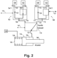
- a solenoid driven actuator system 100 is a dual-redundant actuator system 100 that includes a first solenoid 102 (Sol 1) and a second solenoid 108 (Sol 2).
- the system 100 includes a transfer solenoid 114 operatively coupled to the first and second solenoids 102 and 108, respectively.
- System 100 is arranged such that either the first solenoid 102 or the second solenoid 108 can control the output to a transfer solenoid 114.
- the first solenoid 102 includes a first pressure input 107 and a second pressure input 109 and a pressure outlet 106 downstream from pressure inputs 107 and 109.
- the second solenoid 108 includes a first pressure input 115 and a second pressure input 117 and a second pressure outlet 112 downstream from first and second pressure inputs 115 and 117, respectively.
- the first pressure input 107 of the first solenoid 102 is in fluid communication with a low-pressure source 130.
- the first pressure input 115 of the second solenoid 108 is in fluid communication with a low-pressure source 130.
- the second pressure input 117 of the second solenoid 108 is in fluid communication with a high-pressure source 132.
- the second pressure input 109 of the first solenoid 102 is in fluid communication with a high-pressure source 132.
- the dual-redundant actuator is composed using two 2-way solenoids (102 and 108) and a 3-way transfer solenoid 114 to give control to either first or second solenoid 102 and 108.
- the first and second solenoids 102 and 108 are configured and adapted to be operated on separate channels 155 and 157, respectively.
- the channels can be operatively coupled to at least one FADEC (Full Authority Digital Engine Control) to receive commands therefrom.
- the transfer solenoid 114 is configured and adapted to operate on a transfer solenoid channel 147 separate from channels 155 and 157 controlling the first and second solenoids 102 and 108.
- all three solenoids are controlled by independent channels (first channel 155, second channel 157 and transfer channel 147, respectively).
- Channels 155, 157 and 147 are schematically depicted as double-headed arrows.
- channels 155 and 157, and transfer channel 147 provides redundant control in case of controller channel failure of a solenoid.
- An actuator valve 116 is operatively coupled to a pressure outlet 125 of the transfer solenoid 114.
- Actuator valve 116 includes a spring cavity 145 that is in fluid communication with low-pressure source 130, which can be the same as or different from the low pressure sources 130 coupled to the first and second solenoids 102 and 108.
- the first solenoid 102 includes a low-pressure conduit 141, shown schematically with broken lines to indicate low-pressure.
- the second solenoid 108 includes a low-pressure conduit 143.
- the low-pressure conduit 143 includes an orifice 126.
- Channels 155, 157 and 147 can be made from a variety of data transmission devices, wireless, wired, or otherwise.
- the transfer solenoid 114 is in fluid communication with the pressure outlet 106 of the first solenoid 102.
- a first pressure inlet 110 of the transfer solenoid 114 is in fluid communication with the pressure outlet 106 of the first solenoid 102.
- a second pressure inlet 111 of the transfer solenoid 114 is in fluid communication with the pressure outlet 112 of the second solenoid 108.
- the first solenoid 102 includes a high-pressure conduit 142, shown in solid lines to indicate high-pressure.
- the second solenoid 108 includes a high-pressure conduit 144.
- the low-pressure conduit 141 of the first solenoid 102 includes an orifice 122 and the low-pressure conduit 143 of the second solenoid 108 includes an orifice 126.
- the high pressure from high-pressure conduit 142 goes into a portion of low-pressure conduit 141 downstream from the orifice 122, which is shown in a solid line to schematically indicate high-pressure relative to the low-pressure upstream from orifice 122.
- the high pressure from high-pressure conduit 144 goes into a portion of low-pressure conduit 143 downstream from the orifice 126, which is shown in a solid line to schematically indicate high-pressure relative to the low-pressure upstream from orifice 126.
- both the first and second solenoids 102 and 108, respectively, are shown switched to high-pressure, and the first solenoid 102 is shown in control.
- the first and second pressure inlets 110 and 111, respectively, of the transfer solenoid 114 direct the output from the first solenoid 102 to actuator valve 116 (shown retracting actuator).
- the actuator valve 116 may be arranged differently (e.g., spring 138 may positioned within the actuator control cavity 136) or may be a two-position valve.
- the first solenoid 102 is switched to high-pressure
- the second solenoid 108 is switched to low-pressure
- second solenoid 108 is shown in control.
- the low-pressure conduit 141 of the first solenoid 102 includes an orifice 122.
- the high pressure from high-pressure conduit 142 goes into a portion of low-pressure conduit 141 downstream from the orifice 122, which is shown in a solid line to schematically indicate high-pressure relative to the low-pressure upstream from orifice 122.
- Fig. 2 is the same as Fig.
- transfer solenoid 114 directs the low-pressure output from the second solenoid 108 to actuator valve 116 (the second solenoid is shown extending actuator body 140) instead of from the first solenoid 102 to the actuator valve 116.
- the pressure in actuator control cavity 136 controls whether spring 138 is compressed or released by controlling the axial position of an actuator body 140.
- the pressure in actuator control cavity 136 controls whether spring 138 is compressed or released by controlling the axial position of an actuator body 140.
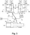
- system 100 of Fig. 3 is the same as system 100 in Figs. 1 and 2 , except that the first and second solenoids 102 and 108 are shown as being operated on a common channel 149.
- first and second solenoids 102 and 108 are controlled with a single FADEC channel
- the transfer solenoid 114 is controlled with its own transfer channel 147.
- the channels whether a single channel or two independent channels, can be operatively coupled to at least one FADEC for receiving controls therefrom.
- transfer channel 147 still communicates with transfer solenoid 114 to provide the control. This provides redundant control in the event of controller channel failure.
- the first solenoid 102 is shown switched to high-pressure and the second solenoid 108 is shown switched to low-pressure.
- the first solenoid 102 includes a high-pressure conduit 142, shown in solid lines to indicate high-pressure.
- the second solenoid 108 includes a high-pressure conduit 144.
- the low-pressure conduit 141 of the first solenoid 102 includes an orifice 122 and the high-pressure conduit 144 of the second solenoid 108 includes an orifice 128.
- the high pressure from high-pressure conduit 142 goes into a portion of low-pressure conduit 141 downstream from the orifice 122, which is shown in a solid line to schematically indicate high-pressure relative to the low-pressure upstream from orifice 122.
- solenoids 102 and 108 are smaller and lighter than EHSVs system 100 provides reduced weight and reduced size envelope as compared with traditional EHSVs. Moreover, if the effector system that the actuator body 140 controls does not have its own means of tracking performance (position sensor, pressure sensor, temp sensor, etc.) embodiments of system 100 can use proximity probes (which have good resolution to determine position in a non-modulated actuator) to determine the left or right position of the actuator body 140. Proximity probes are magnetic sensors that can be installed in the actuator valve 116 to determine position of actuator body 140 (e.g., is the actuator body in the left or right position).
- Proximity probes are lighter than a linear variable differential transformer (LVDT), which would typically be used to detect the position of the actuator in an EHSV system.
- LVDT linear variable differential transformer
- the ability to use these proximity probes results in further potential weight and size reduction as compared with traditional EHSV systems.
- solenoids 102 and 108 have little to no internal leakage, system 100 also provides for improved fuel system efficiency and reliability as compared with EHSVs.
- the simplified control nature of solenoids e.g., the simple I/O control structure, provides easier control as compared with EHSVs. As such, in situations where a non-modulated effector is appropriate, system 100 offers considerable benefits over traditional EHSVs.
- a method for controlling an actuator valve, e.g. actuator valve 116, with dual redundant solenoids, e.g. first and second solenoids 102 and 108 includes providing a control signal to at least one of a first solenoid or a second solenoid to prompt an output from at least one of the first solenoid or the second solenoid.
- the method includes receiving the output in a transfer solenoid, e.g. transfer solenoid 114, and providing a transfer control signal to the transfer solenoid to prompt the transfer solenoid to provide a control pressure from the output to the actuator valve via a high-pressure side, e.g. inlet 110, and/or a low pressure side, e.g. inlet 111.
- the method includes providing the control pressure from the transfer solenoid to the actuator valve.
- the method includes controlling the actuator valve with an output of the transfer solenoid by exposing an actuator control cavity, e.g. actuator control cavity 136, of the actuator valve to the high pressure source.
- the method includes controlling the actuator valve with an output of the transfer solenoid by exposing the actuator cavity of the actuator valve to the low pressure source.
- the method includes communicating commands to the transfer solenoid through a transfer channel, e.g. channel 147.
- the method includes communicating commands to the first solenoid through a first channel, e.g. channel 155, and communicating commands to the second solenoid through a second channel, e.g. channel 157, where the first and second channels are separate from one another.
- the transfer channel is separate from both first and second channels.
- the method can include communicating commands to the first and second solenoids through a common channel, e.g. common channel 149. In this instance, transfer channel is still separate from common channel 149.
Landscapes
- Engineering & Computer Science (AREA)
- General Engineering & Computer Science (AREA)
- Mechanical Engineering (AREA)
- Physics & Mathematics (AREA)
- Fluid Mechanics (AREA)
- Chemical & Material Sciences (AREA)
- Analytical Chemistry (AREA)
- Magnetically Actuated Valves (AREA)
Applications Claiming Priority (1)
| Application Number | Priority Date | Filing Date | Title |
|---|---|---|---|
| US17/675,591 US20230265937A1 (en) | 2022-02-18 | 2022-02-18 | Solenoid driven actuator systems |
Publications (2)
| Publication Number | Publication Date |
|---|---|
| EP4230877A1 true EP4230877A1 (de) | 2023-08-23 |
| EP4230877B1 EP4230877B1 (de) | 2026-05-06 |
Family
ID=85283647
Family Applications (1)
| Application Number | Title | Priority Date | Filing Date |
|---|---|---|---|
| EP23157271.0A Active EP4230877B1 (de) | 2022-02-18 | 2023-02-17 | Aktuatorsysteme angetrieben von elektromagnetischem ventil |
Country Status (2)
| Country | Link |
|---|---|
| US (1) | US20230265937A1 (de) |
| EP (1) | EP4230877B1 (de) |
Cited By (1)
| Publication number | Priority date | Publication date | Assignee | Title |
|---|---|---|---|---|
| EP4265921A1 (de) * | 2022-04-22 | 2023-10-25 | Hamilton Sundstrand Corporation | Hydraulischer aktuator mit einem mehrkopfkolben für ein hydraulisches getriebe |
Families Citing this family (3)
| Publication number | Priority date | Publication date | Assignee | Title |
|---|---|---|---|---|
| US12000346B2 (en) * | 2022-06-27 | 2024-06-04 | Woodward, Inc. | Redundant electro-hydraulic servo valve (EHSV) control in a fuel metering system |
| US20250044816A1 (en) * | 2023-07-31 | 2025-02-06 | Hamilton Sundstrand Corporation | Valve systems |
| US12163537B1 (en) * | 2023-10-20 | 2024-12-10 | Hamilton Sundstrand Corporation | Three way transfer valve for parallel electrohydraulic servo valve control of actuator |
Citations (3)
| Publication number | Priority date | Publication date | Assignee | Title |
|---|---|---|---|---|
| US20170051768A1 (en) * | 2014-04-30 | 2017-02-23 | Festo Ag & Co. Kg | Compressed-Air System Having a Safety Function and Method for Operating Such a Compressed-Air System |
| EP3447315A1 (de) * | 2017-08-23 | 2019-02-27 | Hamilton Sundstrand Corporation | Doppelventilsysteme zur steuerung eines stellgliedes |
| WO2020016697A1 (en) * | 2018-07-16 | 2020-01-23 | Sti S.R.L. | Control and safety system for conveyance circuits of pressurized fluids |
Family Cites Families (5)
| Publication number | Priority date | Publication date | Assignee | Title |
|---|---|---|---|---|
| US9068556B2 (en) * | 2010-11-26 | 2015-06-30 | Vestas Wind Systems A/S | Pilot circuitry for controlling the emergency feathering of a wind turbine |
| US10227951B2 (en) * | 2017-02-02 | 2019-03-12 | Woodward, Inc. | Limited flow thrust reverser actuating |
| US10954969B2 (en) * | 2017-06-10 | 2021-03-23 | Shahin Fallahi | Servo governor by PWM |
| US11466426B2 (en) * | 2019-05-09 | 2022-10-11 | Caterpillar Trimble Control Technologies Llc | Material moving machines and pilot hydraulic switching systems for use therein |
| US12228151B2 (en) * | 2021-10-13 | 2025-02-18 | Hamilton Sundstrand Corporation | Solenoid driven actuator |
-
2022
- 2022-02-18 US US17/675,591 patent/US20230265937A1/en not_active Abandoned
-
2023
- 2023-02-17 EP EP23157271.0A patent/EP4230877B1/de active Active
Patent Citations (3)
| Publication number | Priority date | Publication date | Assignee | Title |
|---|---|---|---|---|
| US20170051768A1 (en) * | 2014-04-30 | 2017-02-23 | Festo Ag & Co. Kg | Compressed-Air System Having a Safety Function and Method for Operating Such a Compressed-Air System |
| EP3447315A1 (de) * | 2017-08-23 | 2019-02-27 | Hamilton Sundstrand Corporation | Doppelventilsysteme zur steuerung eines stellgliedes |
| WO2020016697A1 (en) * | 2018-07-16 | 2020-01-23 | Sti S.R.L. | Control and safety system for conveyance circuits of pressurized fluids |
Cited By (2)
| Publication number | Priority date | Publication date | Assignee | Title |
|---|---|---|---|---|
| EP4265921A1 (de) * | 2022-04-22 | 2023-10-25 | Hamilton Sundstrand Corporation | Hydraulischer aktuator mit einem mehrkopfkolben für ein hydraulisches getriebe |
| US12203491B2 (en) | 2022-04-22 | 2025-01-21 | Hamilton Sundstrand Corporation | Hydraulic actuator including a multi-head piston for hydraulic gearing |
Also Published As
| Publication number | Publication date |
|---|---|
| EP4230877B1 (de) | 2026-05-06 |
| US20230265937A1 (en) | 2023-08-24 |
Similar Documents
| Publication | Publication Date | Title |
|---|---|---|
| EP4230877B1 (de) | Aktuatorsysteme angetrieben von elektromagnetischem ventil | |
| EP4230845B1 (de) | Von solenoid-ventilen angetriebene aktuatorsysteme | |
| EP3290332B1 (de) | Betätigungsystem für eine propellersteigungsregelung | |
| US6685138B1 (en) | Augmenting flight control surface actuation system and method | |
| EP3561264B1 (de) | Passive aktive entlüftungstellerventile | |
| EP4166794A1 (de) | Fluidgesteuertes wegeventil | |
| EP2769100B1 (de) | Volumenverstärker mit sitzlastvorspannung | |
| JPS628612B2 (de) | ||
| JPH0784884B2 (ja) | 負荷補償方向制御弁の負荷検知回路 | |
| JP2001504927A (ja) | 障害時固定式ゼロドリフトアクチュエータ | |
| WO2024118282A1 (en) | System and method for in situ verification of redundant electro-hydraulic servo valve (ehsv) operational status in redundant flow control systems | |
| US5784884A (en) | Fail-safe transfer valve | |
| EP2578844B1 (de) | Brennstoffsystem einer Fluggasturbine | |
| GB2551422A (en) | Compressor geometry control | |
| EP4400719A1 (de) | Direktsteuerung für verstellpumpen | |
| EP4382748A1 (de) | Verstellpumpen mit festem und aktivem verstellsteuerungsmodus | |
| US20230304442A1 (en) | Pump system for a gas turbine engine | |
| US10823087B1 (en) | Inline valves, gas turbine engines with inline bleed valves, and methods controlling flow through inline valves | |
| EP4382747A1 (de) | Verstellpumpe mit strömungsabgabe an verschiedene systeme mit unterschiedlichen druckplänen | |
| EP4283111B1 (de) | Kraftstoffzumesssysteme mit zwei ventilen | |
| US11391301B2 (en) | Electrohydraulic poppet valve device control that maintains the last commanded position of a device upon power interruption and provides back-up position control | |
| US6955113B2 (en) | Electro-hydraulic actuator with mechanical servo position feedback | |
| US20170350421A1 (en) | Manifold for a directional control valve for a valve actuator | |
| US20240392774A1 (en) | Active displacement control against temperature target | |
| US12398720B2 (en) | Direct controlled variable displacement valves with dual set point pressure relief |
Legal Events
| Date | Code | Title | Description |
|---|---|---|---|
| PUAI | Public reference made under article 153(3) epc to a published international application that has entered the european phase |
Free format text: ORIGINAL CODE: 0009012 |
|
| STAA | Information on the status of an ep patent application or granted ep patent |
Free format text: STATUS: THE APPLICATION HAS BEEN PUBLISHED |
|
| AK | Designated contracting states |
Kind code of ref document: A1 Designated state(s): AL AT BE BG CH CY CZ DE DK EE ES FI FR GB GR HR HU IE IS IT LI LT LU LV MC ME MK MT NL NO PL PT RO RS SE SI SK SM TR |
|
| STAA | Information on the status of an ep patent application or granted ep patent |
Free format text: STATUS: REQUEST FOR EXAMINATION WAS MADE |
|
| 17P | Request for examination filed |
Effective date: 20240220 |
|
| RBV | Designated contracting states (corrected) |
Designated state(s): AL AT BE BG CH CY CZ DE DK EE ES FI FR GB GR HR HU IE IS IT LI LT LU LV MC ME MK MT NL NO PL PT RO RS SE SI SK SM TR |
|
| STAA | Information on the status of an ep patent application or granted ep patent |
Free format text: STATUS: EXAMINATION IS IN PROGRESS |
|
| 17Q | First examination report despatched |
Effective date: 20240710 |
|
| GRAP | Despatch of communication of intention to grant a patent |
Free format text: ORIGINAL CODE: EPIDOSNIGR1 |
|
| STAA | Information on the status of an ep patent application or granted ep patent |
Free format text: STATUS: GRANT OF PATENT IS INTENDED |
|
| INTG | Intention to grant announced |
Effective date: 20260202 |
|
| GRAS | Grant fee paid |
Free format text: ORIGINAL CODE: EPIDOSNIGR3 |
|
| GRAA | (expected) grant |
Free format text: ORIGINAL CODE: 0009210 |
|
| STAA | Information on the status of an ep patent application or granted ep patent |
Free format text: STATUS: THE PATENT HAS BEEN GRANTED |
|
| AK | Designated contracting states |
Kind code of ref document: B1 Designated state(s): AL AT BE BG CH CY CZ DE DK EE ES FI FR GB GR HR HU IE IS IT LI LT LU LV MC ME MK MT NL NO PL PT RO RS SE SI SK SM TR |
|
| REG | Reference to a national code |
Ref country code: CH Ref legal event code: F10 Free format text: ST27 STATUS EVENT CODE: U-0-0-F10-F00 (AS PROVIDED BY THE NATIONAL OFFICE) Effective date: 20260506 Ref country code: GB Ref legal event code: FG4D |