EP4230907A1 - Humidificateur à vapeur à électrode et son procédé de fonctionnement - Google Patents
Humidificateur à vapeur à électrode et son procédé de fonctionnement Download PDFInfo
- Publication number
- EP4230907A1 EP4230907A1 EP22157010.4A EP22157010A EP4230907A1 EP 4230907 A1 EP4230907 A1 EP 4230907A1 EP 22157010 A EP22157010 A EP 22157010A EP 4230907 A1 EP4230907 A1 EP 4230907A1
- Authority
- EP
- European Patent Office
- Prior art keywords
- water
- steam
- electrode
- conductivity
- container
- Prior art date
- Legal status (The legal status is an assumption and is not a legal conclusion. Google has not performed a legal analysis and makes no representation as to the accuracy of the status listed.)
- Granted
Links
Images
Classifications
-
- F—MECHANICAL ENGINEERING; LIGHTING; HEATING; WEAPONS; BLASTING
- F22—STEAM GENERATION
- F22B—METHODS OF STEAM GENERATION; STEAM BOILERS
- F22B1/00—Methods of steam generation characterised by form of heating method
- F22B1/28—Methods of steam generation characterised by form of heating method in boilers heated electrically
- F22B1/30—Electrode boilers
-
- F—MECHANICAL ENGINEERING; LIGHTING; HEATING; WEAPONS; BLASTING
- F24—HEATING; RANGES; VENTILATING
- F24F—AIR-CONDITIONING; AIR-HUMIDIFICATION; VENTILATION; USE OF AIR CURRENTS FOR SCREENING
- F24F6/00—Air-humidification, e.g. cooling by humidification
- F24F6/02—Air-humidification, e.g. cooling by humidification by evaporation of water in the air
- F24F6/025—Air-humidification, e.g. cooling by humidification by evaporation of water in the air using electrical heating means
-
- H—ELECTRICITY
- H05—ELECTRIC TECHNIQUES NOT OTHERWISE PROVIDED FOR
- H05B—ELECTRIC HEATING; ELECTRIC LIGHT SOURCES NOT OTHERWISE PROVIDED FOR; CIRCUIT ARRANGEMENTS FOR ELECTRIC LIGHT SOURCES, IN GENERAL
- H05B3/00—Ohmic-resistance heating
- H05B3/20—Heating elements having extended surface area substantially in a two-dimensional [2D] plane, e.g. plate-heater
- H05B3/22—Heating elements having extended surface area substantially in a two-dimensional [2D] plane, e.g. plate-heater non-flexible
Definitions
- the invention relates to an electrode steam humidifier and a method for operating the same as well as a suitable computer program product for executing the method.
- Known electrode steam humidifiers comprise a steam cylinder with electrodes protruding therein. If sufficiently filled with tap water, a sufficient electric voltage applied to the electrode will lead to a current flow through the water that eventually leads to boiling the water, thus generating steam.
- the decrease in water level due to the extracted steam is balanced by refilling tap water to a prescribed level, typically in an intermittent fashion once the water level has lowered to a certain extent.
- the water level within the steam cylinder is generally regulated based on the electrical power consumed by the steam generation.
- the concentration of said mineral substances in the water within the steam cylinder increases. While dissolved mineral substances are essential for the electrode steam humidifiers to work, since they provide for the required conductivity, the increase in said mineral concentration has some severe disadvantages. As the increase in the mineral concentration leads to an increase in conductivity of the water, this leads to an increased corrosion of the electrodes and increased formation of lime scale.
- the steam cylinder needs to be fully drained regularly for the highly saline water to be exchanged with fresh tap water. Any precipitating mineral residues must also be regularly removed, e. g. either during the draining process or during regular maintenance cycles.
- the invention thus relates to an electrode steam humidifier comprising a steam container with a first water inlet for mineralized water and at least two electrodes arranged to be at least partly immersed in water filled in above a minimum fill level, wherein the electrodes are supplied with an electric voltage so that at least one of the electrodes has a different potential than the other electrode(s) to cause an electric current flow in the water, wherein the steam container comprises a second water inlet for demineralized water and means to assess the conductivity of the water held within the steam container, wherein the throughflow through both water inlets for replenishing the steam container is controlled by a controller based on the assessed conductivity in order to obtain or maintain a desired conductivity.
- the invention relates to a method for operating an electrode steam humidifier, wherein the conductivity of the water within the steam container of the steam humidifier is assessed and the conductivity of water introduced into the steam container for replenishment is adjusted so that the resulting water mixture in the steam container has a desired conductivity.
- the invention also relates to a computer program product comprising program parts that are designed, when loaded in a digital controller connected to the required sensors and actuators of at least an electrode steam humidifier, to execute the inventive method.
- Electrodes have "different potential” if their electric potential is generally and intentionally not the same, which is self-explanatory for direct voltages applies to the electrodes. In case of applying an alternate or multi-phase voltage to the electrodes of an electrode steam humidifier, the electrodes are still considered to be different potential, even if during a cycle the electric potential might momentarily be the same but is different for most of the cycle.
- the present invention has recognized that by selectively refilling water with different degrees of purity allows for a certain control over the conductivity of the water held within an electrode steam humidifier, which - as a result - can be operated with high efficiency over longer operating cycles than is possible with known electrode steam humidifier.
- the maintenance cycles of electrode steam humidifiers according to the invention can be significantly extended in comparison to what is common in the current state of the art, since the degradation of the electrodes as well as the precipitating of mineral can be reduced significantly by maintaining a prescribed level of mineralization of the water within the steam container.
- a controller controls the inflow of either mineralized water (such as tap water) and demineralized water to ensure a desired conductivity of the water held within the steam container is either obtained or maintained at least within a certain tolerance range, in order to counter the effects of steam extractions (generally increasing the conductivity) and the precipitating of mineral (generally decreasing the conductivity).
- the overall inflow as well as the mixing ratio of the inflow of mineralized and demineralized water is to be based on the conductivity that is assessed for the water already present in the steam container.
- the conductivity can already be assessed to a level sufficiently accurate by observing the system response to certain changes in the system state, taking into account certain system constants and, if necessary, certain presumptions.
- the means to assess the conductivity of the water held within the steam container comprise an observer module capable of observing various parameters of operation of the electrode steam humidifier that are sufficient to assess said conductivity. Said observer module might be integrated into the controller.
- the system response to applying a prescribed electric voltage to the electrodes may be regarded as the desired reference response.
- the system response might be observed by measuring the electric currents resulting from applying the prescribed electric voltage. Over time, the system will first show an increase in conductivity, visible as an increase in electric currents while the water is warming up until boiling. Afterwards, due to water evaporating the water level within the steam container will slowly drop, resulting in a reduction of the electrode surfaces immersed in the water and a subsequent decrease in the electric currents. Replenishing the steam container with water with the initial conductivity (e. g.
- the system response in this initial first or first few cycles may be regarded as a reference response.
- This reference response may be - e. g. digitally - stored as reference response data and accessibly by the controller and/or the observer module.
- any ascertainable deviation from the reference response during operation points to a change in the conductivity of the water within the steam container.
- the mixture ratio of mineralized and demineralized water for replenishing the steam container may be systematically adjusted to move the overall conductivity of the water within the steam container towards the conductivity the reference response is based on.
- the change in the mixture radio might e.g. be prescribed by means of a characteristic curve accessibly to the controller and/or observer module, e. g. digitally stored, or by means of mathematic equations. It may also be derived from a modelization of the system.
- the reference response data for a specific electrode steam humidifier and/or its operating environment may be calculated or selected from a suitable reference response data catalogue based on certain parameters, e. g. the structural design of the electrode steam humidifier, especially regarding the number and arrangement of the electrodes, or the mineral concentration of the water fed through the first water inlet.
- the controller comprises and/or the observer module machine learning algorithm to, over time and e. g. starting with a prescribed characteristic curve for adjustment of the mixture ratio of mineralized and demineralized water, determine the most suitable mixture adjustments in case of deviations from the reference response.
- the conductivity control can further be enhanced by relying on additional sensor information, thus reducing the dependency on indirectly determined or assumed values.
- Said additional sensor information may be fed to the observer module and considered when assessing any current system response in comparison with a reference response.
- the observer module might be omitted and all measured values are directly processed by the controller.
- the electrode steam humidifier may preferably comprise a sensor electrode that indicates the water level within the steam container being at or above a prescribed level.
- the tip of the sensor electrode is arranged at the prescribed level, wherein the detection value of the sensor depends on the sensor tip being immersed in the water or above the water level.
- sensor electrodes are generally known in the prior art and e. g. already used as maximum water level indicators.
- Any switch over between these two detection states of the sensor electrode may be interpreted by the controller as a signal that the water level within the steam container has reached or is at the prescribed level, or is lower than said level. Any deviation from the expected reference response of the system with this specific water level may then be interpreted to be caused by other changes to the system, such as a change in conductivity of the water.
- the sensor electrode is preferably configured to detect the water level at the level the steam container is to be regularly refilled to, when compensating for the water losses due to steam generation.
- the sensor electrode may then also be used as an indicator for stopping any water inflow though the water inlets, without affecting its function described above.
- a water level detector may be provided that is, preferably, not or at least less susceptible to misreading due to foam.
- a water level detector - in contrast to a sensor electrode - is not only capable of detecting whether the water level is below or above a prescribed level, but rater capable of determining any water level within its measuring range.
- It may be one or more reed contacts actuated by a flotation body in separate container in communication with the steam, or a capacitive water level sensor, e. g. as disclosed in DE 20 2016 005 944 U1 .
- a capacitive water level sensor e. g. as disclosed in DE 20 2016 005 944 U1 .
- said detector may be located in a container separate from the steam container, wherein said containers form communicating vessels.
- foam formation or any other effects occurring when boiling water that could affect the measurement accuracy of a water level sensor is generally limited to the steam container and the water level sensor located in the separate container is unaffected.
- a conductivity sensor may be provided in the steam container or in a vessel communicating therewith.
- the sensor is preferably located at a position that is below typical water levels during normal operation of the electrode steam humidifier.
- a conductivity sensor may also be provided at one or both of the water inlets and/or at a position, where the two separate inlets are united to provide a combined inflow of already mixed water.
- the controller e. g. adjusting the inflow through both inlets to obtain the desired conductivity of the mixture of water.
- the electrodes and/or their numbers are optimized to allow the electrode steam humidifier to allow the conductivity of the water to be as low as possible.
- a preferred number of electrodes for a steam output of up to 15 kg/h is 3, for a steam output of 20 to 65 kg/h 6 electrodes are preferred.
- the surface of the electrodes as a function of the rated current is preferably between 5 and 30 cm 2 /A, more preferably between 10 and 20 cm 2 /A for full-surface electrodes, or preferably between 5 and 25 cm 2 /A, more preferably between 5 and 15 cm 2 /A for mesh electrodes, the full-surface electrodes, however, being preferred.
- the surface distance between two adjacent electrodes with different potentials is preferably between 25 and 50 mm for a maximum rated potential difference of 400 V (e.g., occurring with alternating currents), between 15 and 35 mm for a maximum rated potential difference of 200 V, or between 50 and 80 mm for a maximum rated potential difference of 690 V.
- the electrode steam humidifier may comprise solenoid or motorized valves on the first and/or the second water inlet that are controllable by the controller.
- the electrode steam humidifier may comprise an interface to the external water treatment device connected to the second water inlet to control the demineralized water output of the water treatment device.
- the controller is preferably configured to control the steam production of the electrode steam humidifier more finely.
- the controller might be configured to regulate the electric power that is conducted through the electrodes. Especially, the controller might limit or mitigate the increase in electric current due to an increase in conductivity of the water in order to regulate the steam generation. This way, an overshoot in steam generation when boiling up water can be avoided or at least reduced.
- any know technology such as pulse-width modulation (PWM), AC-to-AC-conversion, leading-edge cutoff or trailing-edge cutoff, may be used.
- PWM pulse-width modulation
- AC-to-AC-conversion leading-edge cutoff or trailing-edge cutoff
- the controller might also be configured to control the steam production based on the water level, which corresponds to the immersion depth of the electrodes.
- a water level detector allows for more precise replenishing of water to reduce the variation in water level during operation. Less variation in water level also means less variation in steam production.
- the conductivity of the water within the steam container of the steam humidifier is assessed, wherein the assessment might be based on observing system responses, direct and/or indirect measurements.
- the conductivity of water introduced into the steam container for replenishment is adjusted so that the resulting water mixture in the steam container has a desired conductivity. In other words, if the conductivity in the water within the steam container is above the desired level, less conductive water is introduced for replenishment, while in case of a conductivity below the desired value, water with higher conductivity is used for replenishment.
- the conductivity of the water used for replenishment may be adjusted by mixing water from two sources with different conductivity.
- the assessment of the conductivity of the water within the steam container is based on the observation of at least one system response during the normal operation of the electrode steam humidifier.
- the observation of system responses of the electrode steam humidifier generally allows the method being applied to already existing electrode steam humidifiers and electrode steam humidifier designs, without requiring structural changes. Often, only the controller of the electrode steam humidifier requires updating to allow observing the system responses and react thereto.
- inventive method is preferably implemented in an inventive electrode steam humidifier, it is not limited to this specific embodiment. Rather, the inventive method might also be realized with a known electrode steam humidifier comprising a single water inlet and a source of water connected thereto, wherein the source of water is controllable in regard to the mineralization of the water provided to the electrode steam humidifier.
- a source of water is an osmosis unit for purifying mineralized water with a controllable bypass for mineralized water.
- the controller of the electrode steam humidifier to execute the inventive method, wherein an external controllable source of water may be controlled via a suitable interface
- a separate controller to execute the inventive method.
- said separate controller must be provided with all readings necessary to execute said method and be configured to control electrode steam humidifier and all other possible components via suitable interfaces.
- the controller running the inventive computer program product needs to be connected to all required sensors and actuators of the electrode steam humidifier and all other possible components.
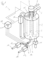
- FIG. 1 schematically depicts an electrode steam humidifier 1 in accordance with the present invention.
- the electrode steam humidifier comprises a steam container 1 comprises a steam container 2 in the form of a steam cylinder.
- the steam container 2 comprises an intake opening 3 as well as a drainage opening 4 with a controllable drainage pump 4' in its bottom.
- At the top there is a steam outlet 5, that leads to any other appliance at least temporarily requiring steam (not shown), e. g. climate control units.
- each electrode 6 is disposed evenly spaced around the circumference. These electrodes 6 are configured to allow boiling up water with limited conductivity, thus having a large surface facing each other, in the present case approx. 20 cm 2 /A each. While the electrodes 6 are depicted as simple plate electrodes, they might have a somewhat more elaborate design, e. g. V-shaped, resulting in the surfaces of two adjacent electrodes 6 to show a constant distance over the whole area.
- the electrodes 6 are individually electrically connected to a power distribution unit 7 connected to an external power source, e. g. a power grid (not shown), via connection line 8.
- Power distribution unit 7 is configured to supply the electrode with either direct or alternating voltage in a way that the potential of two adjacent electrodes 6 is different. Furthermore, the power distribution unit 7 measures the total electrical current flowing between the electrodes 6 and provides the facility to limit the current flow - and thus the electrical power consumed by the electrodes 6, assuming constant voltage - to an externally supplied setpoint.
- intake opening 3 is connected to two separate water inlets 10, 11, the throughflow thereto being controllable by, in this example, solenoid valves 12, 13.
- the first water inlet 10 is intended for mineralized water, usually tap water, while the other water inlet 11 is intended for demineralized water.
- a conductivity sensor 14 is provided to measure the conductivity of the water flowing through said connection.
- the steam container 2 is also provided with a sensor electrode 15, protruding thereinto from the top by a predetermined length. Said sensor electrodes 15 indicates whether its tip is immersed into water or not.
- a water level detector 16 is provided.
- the water level detector 16 which is connected to the steam container 2 via communicating tubes, is a capacitive water level sensor, e. g. as disclosed in DE 20 2016 005 944 U1 , and allows to precisely determine the water level within the steam container 2 in a range around the water level prescribed by the sensor electrode 15. The range is mainly defined by the length of the water level detector 16.
- All sensor devices i.e., the conductivity sensor 14, the sensor electrode 15, the water level detector 16 and the power distribution unit 7 in its capacity to measure the total electrical current, as well as all controllable devices, i.e., the various valves 12 and 13, the drainage pump 4' as well as power distribution unit 7 in respect to its power limiting functionalities, are connected to a controller 20, which also comprises an observation module 21.
- the steam container 2 is initially filled with water of a prescribed conductivity up to the water level prescribed by the sensor electrode 15 by opening the two solenoid valves 12, 13 of the two water inlets 10, 11, wherein the controller 20 opens each of the valves 12, 13 to an extent required to achieve a mixture with the desired conductivity.
- the prescribed conductivity of the inflowing water during the filling up is constantly monitored by via the conductivity sensor 14.
- the controller 20 is configured to adjust the valves 12, 13 and thus the mixture of mineralized and demineralized water to reach the desired conductivity.
- the electrodes 6 are electrically energized by the power distribution unit 7 so that adjacent electrodes 6 are each of different potential to cause an electric current in the water due to its conductivity.
- the overall electric current is measured by the power distribution unit 7 and reported to the controller 20.
- the water Due to the electric current running trough the water, the water is heated up to boiling, thus generating steam that is output via the steam outlet 5. While heating up, the conductivity of the water increases, which is registrable by the power distribution unit 7 and the controller 20 by an increase in electric currents though the electrodes 6.
- the water level within the steam container 2 decreases, which is noticeable by the sensor electrode 15 and/or the water level detector 16, and also generally leads to a decrease in electric current.
- the decrease in water level is registered by the controller 20 either by a combination of the sensor electrode 15 reporting the water level being below its tip and a decrease in electric currents by a predetermined amount or by the water level detector 16 and is generally countered by replenishing the steam container 2 with water from the first and/or second water inlet 10, 11.
- the controller 20 is configured to purposefully adjust the conductivity of the water inflow in order to control the conductivity of the resulting water mixture within the steam container 2.
- the controller 20 comprises an observer module 21 that is configured to assess the conductivity of the water within the steam container 2.
- the observer module 21 may observe the maximum electric current reached each time after the steam container 2 has been replenished with water as indicated by sensor electrode 15, which the maximum electric current reached after having heated up the water within the steam container 2 to boiling temperature. Any deviation from, e. g. the electric current measured during an initial heating cycle (see above), which might be regarded as a reference response of the system of the electrode steam humidifier 1, may be interpreted as a deviation of the conductivity of the water within the steam container 2, which may be countered by the controller 20 by adjusting the mixture of mineralized and demineralized water used for replenishing in according with a characteristic curve stored in the controller 20.
- the conductivity of the water within the steam container 2 might also be derived from the electric currents measured by the power distribution unit 7 and the water level detected by the water level detector 16. These findings might be compared to an expected standard system response stored within the controller and any deviation may be interpreted in a deviation from the desired conductivity of the water within the steam container 2. Again, said deviation may be countered by the controller 20 by adjusting the mixture of mineralized and demineralized water used for replenishing in according with a characteristic curve stored in the controller 20.
- the controller 20 and/or the observer module 21 might apply a machine learning algorithm based on said measures conductivity and the effects on the conductivity assessed for the water in the steam container 2.
- the controller 20 generally achieves a constant level of mineralization of the water within the steam container 2 throughout operation of the electrode steam humidifier 1.
- the controller 20 might activate the drainage pump 4' to syphon the water from the steam container 2 through the drainage opening 4. Once the steam container 2 is emptied, said drainage pump 4' is deactivated and the steam container 2 is refilled with water as described above.
- the electrode steam humidifier 1 as shown in figure 1 may provide additional advantages: Using both disclosed techniques of assessing the water level or at least the meeting of a prescribed water level, i. e. via the sensor electrode 15 and the water level detector 16, any foam formation within the steam container 2 can be detected since foam in the steam container 2 will usually trigger the sensor electrode 15 before the actual water level as detectable by the water level detector 16, which is generally not affected by foam forming in the steam container 2, has reached the tip of the sensor electrode 15.
- the forming of foam in the steam container 2 might indicate impurities or low quality of the water - often of the mineralized water, which is typically tap water - that might require more frequent maintenance and/or cleaning of the electrode steam humidifier 1 and especially the steam container 2 and the electrodes 6 to ensure long operation times of the electrode steam humidifier 1.
- the controller 20 may also be configured to mitigate the increase in electric power that is conducted through the electrodes 6 by sending suitable control commands to the power distribution unit 7 as well as utilizing the water level detector 16 to keep the water level within the steam container 2 as close as possible to the desired water level as e. g. prescribed by the sensor electrode 15. Both measures help to keep the steam production of the electrode steam humidifier 1 more constant.
Landscapes
- Engineering & Computer Science (AREA)
- Mechanical Engineering (AREA)
- General Engineering & Computer Science (AREA)
- Chemical & Material Sciences (AREA)
- Combustion & Propulsion (AREA)
- Life Sciences & Earth Sciences (AREA)
- Sustainable Development (AREA)
- Sustainable Energy (AREA)
- Physics & Mathematics (AREA)
- Thermal Sciences (AREA)
- Air Humidification (AREA)
- Control Of Resistance Heating (AREA)
Priority Applications (10)
| Application Number | Priority Date | Filing Date | Title |
|---|---|---|---|
| HRP20241541TT HRP20241541T1 (hr) | 2022-02-16 | 2022-02-16 | Parni ovlaživač sa elektrodom i način njegovog rada |
| EP22157010.4A EP4230907B1 (fr) | 2022-02-16 | 2022-02-16 | Humidificateur à vapeur à électrode et son procédé de fonctionnement |
| PL22157010.4T PL4230907T3 (pl) | 2022-02-16 | 2022-02-16 | Elektrodowy nawilżacz parowy i sposób jego eksploatacji |
| ES22157010T ES2992658T3 (en) | 2022-02-16 | 2022-02-16 | Electrode steam humidifier and method for its operation |
| CN202380034334.8A CN118946760A (zh) | 2022-02-16 | 2023-02-16 | 电极蒸汽加湿器及其操作方法 |
| CA3243976A CA3243976A1 (fr) | 2022-02-16 | 2023-02-16 | Humidificateur à vapeur à électrodes et procédé pour son fonctionnement |
| PCT/EP2023/053827 WO2023156496A1 (fr) | 2022-02-16 | 2023-02-16 | Humidificateur à vapeur à électrodes et procédé pour son fonctionnement |
| JP2024548782A JP2025506254A (ja) | 2022-02-16 | 2023-02-16 | 電極式蒸気加湿器とその操作方法 |
| US18/838,828 US20250164126A1 (en) | 2022-02-16 | 2023-02-16 | Electrode steam humidifier and method for its operation |
| MX2024010064A MX2024010064A (es) | 2022-02-16 | 2024-08-15 | Humidificador de vapor de electrodo y metodo para su operacion |
Applications Claiming Priority (1)
| Application Number | Priority Date | Filing Date | Title |
|---|---|---|---|
| EP22157010.4A EP4230907B1 (fr) | 2022-02-16 | 2022-02-16 | Humidificateur à vapeur à électrode et son procédé de fonctionnement |
Publications (3)
| Publication Number | Publication Date |
|---|---|
| EP4230907A1 true EP4230907A1 (fr) | 2023-08-23 |
| EP4230907B1 EP4230907B1 (fr) | 2024-10-02 |
| EP4230907C0 EP4230907C0 (fr) | 2024-10-02 |
Family
ID=80683079
Family Applications (1)
| Application Number | Title | Priority Date | Filing Date |
|---|---|---|---|
| EP22157010.4A Active EP4230907B1 (fr) | 2022-02-16 | 2022-02-16 | Humidificateur à vapeur à électrode et son procédé de fonctionnement |
Country Status (10)
| Country | Link |
|---|---|
| US (1) | US20250164126A1 (fr) |
| EP (1) | EP4230907B1 (fr) |
| JP (1) | JP2025506254A (fr) |
| CN (1) | CN118946760A (fr) |
| CA (1) | CA3243976A1 (fr) |
| ES (1) | ES2992658T3 (fr) |
| HR (1) | HRP20241541T1 (fr) |
| MX (1) | MX2024010064A (fr) |
| PL (1) | PL4230907T3 (fr) |
| WO (1) | WO2023156496A1 (fr) |
Cited By (1)
| Publication number | Priority date | Publication date | Assignee | Title |
|---|---|---|---|---|
| WO2025132352A1 (fr) * | 2023-12-19 | 2025-06-26 | Shell Internationale Research Maatschappij B.V. | Chaudière à électrodes de génération de vapeur |
Citations (4)
| Publication number | Priority date | Publication date | Assignee | Title |
|---|---|---|---|---|
| CN101216199A (zh) * | 2007-12-27 | 2008-07-09 | 于郡东 | 一种电极式加湿器和加湿控制方法 |
| DE202016005944U1 (de) | 2016-09-27 | 2016-11-17 | Hygromatik Gmbh | Dampfluftbefeuchter |
| CN108195010A (zh) * | 2017-12-28 | 2018-06-22 | 青岛海尔空调电子有限公司 | 电极加湿器的控制方法 |
| WO2021057292A1 (fr) * | 2019-09-27 | 2021-04-01 | 青岛海尔空调电子有限公司 | Procédé de commande d'humidificateur à électrodes et humidificateur à électrodes |
Family Cites Families (10)
| Publication number | Priority date | Publication date | Assignee | Title |
|---|---|---|---|---|
| CN201289180Y (zh) * | 2008-06-26 | 2009-08-12 | 上海约顿机房设备有限公司 | 一种电极式加湿器系统 |
| KR20140064862A (ko) * | 2011-08-16 | 2014-05-28 | 우드 스톤 아이디어즈, 엘엘시 | 증기발생 시스템 |
| JP5987286B2 (ja) * | 2011-09-15 | 2016-09-07 | 栗田工業株式会社 | 水処理方法 |
| CN208667334U (zh) * | 2018-07-11 | 2019-03-29 | 重庆太和空调自控有限公司 | 实验室恒温恒湿空调加湿纯水器 |
| CN109373502B (zh) * | 2018-09-21 | 2021-03-09 | 国网山东省电力公司莒县供电公司 | 一种机房精密空调加湿器电导控制装置及控制方法 |
| US12540085B2 (en) * | 2019-12-13 | 2026-02-03 | Mitsubishi Electric Corporation | Water-using apparatus |
| CN211925937U (zh) * | 2019-12-27 | 2020-11-13 | 重庆太和空调自控有限公司 | 实验室恒温恒湿空调加湿器的排污系统 |
| CN212657831U (zh) * | 2020-08-05 | 2021-03-05 | 中国工商银行股份有限公司 | 用于加湿设备的液体处理设备和加湿系统 |
| WO2022168152A1 (fr) * | 2021-02-02 | 2022-08-11 | 三菱電機株式会社 | Humidificateur |
| CN115435424B (zh) * | 2022-09-09 | 2024-09-10 | 南京天加环境科技有限公司 | 一种用于高水电导率的电极加湿器及其控制方法 |
-
2022
- 2022-02-16 EP EP22157010.4A patent/EP4230907B1/fr active Active
- 2022-02-16 ES ES22157010T patent/ES2992658T3/es active Active
- 2022-02-16 PL PL22157010.4T patent/PL4230907T3/pl unknown
- 2022-02-16 HR HRP20241541TT patent/HRP20241541T1/hr unknown
-
2023
- 2023-02-16 JP JP2024548782A patent/JP2025506254A/ja active Pending
- 2023-02-16 CN CN202380034334.8A patent/CN118946760A/zh active Pending
- 2023-02-16 WO PCT/EP2023/053827 patent/WO2023156496A1/fr not_active Ceased
- 2023-02-16 CA CA3243976A patent/CA3243976A1/fr active Pending
- 2023-02-16 US US18/838,828 patent/US20250164126A1/en active Pending
-
2024
- 2024-08-15 MX MX2024010064A patent/MX2024010064A/es unknown
Patent Citations (4)
| Publication number | Priority date | Publication date | Assignee | Title |
|---|---|---|---|---|
| CN101216199A (zh) * | 2007-12-27 | 2008-07-09 | 于郡东 | 一种电极式加湿器和加湿控制方法 |
| DE202016005944U1 (de) | 2016-09-27 | 2016-11-17 | Hygromatik Gmbh | Dampfluftbefeuchter |
| CN108195010A (zh) * | 2017-12-28 | 2018-06-22 | 青岛海尔空调电子有限公司 | 电极加湿器的控制方法 |
| WO2021057292A1 (fr) * | 2019-09-27 | 2021-04-01 | 青岛海尔空调电子有限公司 | Procédé de commande d'humidificateur à électrodes et humidificateur à électrodes |
Cited By (1)
| Publication number | Priority date | Publication date | Assignee | Title |
|---|---|---|---|---|
| WO2025132352A1 (fr) * | 2023-12-19 | 2025-06-26 | Shell Internationale Research Maatschappij B.V. | Chaudière à électrodes de génération de vapeur |
Also Published As
| Publication number | Publication date |
|---|---|
| JP2025506254A (ja) | 2025-03-07 |
| CN118946760A (zh) | 2024-11-12 |
| EP4230907B1 (fr) | 2024-10-02 |
| US20250164126A1 (en) | 2025-05-22 |
| ES2992658T3 (en) | 2024-12-16 |
| EP4230907C0 (fr) | 2024-10-02 |
| WO2023156496A1 (fr) | 2023-08-24 |
| HRP20241541T1 (hr) | 2025-01-03 |
| CA3243976A1 (fr) | 2023-08-24 |
| PL4230907T3 (pl) | 2025-03-03 |
| MX2024010064A (es) | 2024-11-08 |
Similar Documents
| Publication | Publication Date | Title |
|---|---|---|
| EP1166698B1 (fr) | Bouilloire et cuiseur à vapeur avec une telle bouilloire | |
| CN112050179B (zh) | 蒸汽发生器自适应控制方法及蒸汽发生系统 | |
| EP4230907B1 (fr) | Humidificateur à vapeur à électrode et son procédé de fonctionnement | |
| US8758627B2 (en) | Twin tank water treatment method | |
| WO2020074476A1 (fr) | Appareil domestique de cuisson à la vapeur et procédé pour faire fonctionner un appareil domestique de cuisson à la vapeur | |
| CN113832498B (zh) | 便于检测水电解制氢装置中电极或隔膜性能的检测装置 | |
| CN204023192U (zh) | 具有上染率在线反馈功能的染色机 | |
| CN104020800A (zh) | 一种染色在线反馈控制系统及其方法 | |
| CN102295354A (zh) | 一种中低压锅炉磷酸盐加药控制方法 | |
| JP2025506254A5 (fr) | ||
| US20250146660A1 (en) | Steam Generator | |
| KR101726303B1 (ko) | 살균수 생성 제어 시스템 및 그의 제어 방법 | |
| CN119713243B (zh) | 一种贯流锅炉的水质控制方法及系统 | |
| EP2362008B1 (fr) | Technique de réglage pour un procédé de lavage à plusieurs étapes utilisant une pluralité de produits chimiques | |
| KR101131144B1 (ko) | 액튜에이터 시험장치 | |
| RU133270U1 (ru) | Автоматизированная система мониторинга и управления физико-химическими процессами градирни | |
| CN212183760U (zh) | 一种电加热器 | |
| CN113149174A (zh) | 一种炉水的磷酸盐控制系统、方法及乙烯装置 | |
| EP4488671B1 (fr) | Dispositif d'analyse d'ammonium | |
| US11391492B2 (en) | Dry tank detection method for a water heater appliance | |
| KR100495067B1 (ko) | 세탁기 전극센서의 오동작 감지 방법 | |
| JPH109507A (ja) | ボイラの間欠ブロー制御方法 | |
| JP2024081820A (ja) | 電解水生成装置 | |
| JPH0459537B2 (fr) | ||
| KR20250124504A (ko) | 스팀공급장치 및 방법 |
Legal Events
| Date | Code | Title | Description |
|---|---|---|---|
| REG | Reference to a national code |
Ref country code: HR Ref legal event code: TUEP Ref document number: P20241541T Country of ref document: HR |
|
| PUAI | Public reference made under article 153(3) epc to a published international application that has entered the european phase |
Free format text: ORIGINAL CODE: 0009012 |
|
| STAA | Information on the status of an ep patent application or granted ep patent |
Free format text: STATUS: THE APPLICATION HAS BEEN PUBLISHED |
|
| AK | Designated contracting states |
Kind code of ref document: A1 Designated state(s): AL AT BE BG CH CY CZ DE DK EE ES FI FR GB GR HR HU IE IS IT LI LT LU LV MC MK MT NL NO PL PT RO RS SE SI SK SM TR |
|
| STAA | Information on the status of an ep patent application or granted ep patent |
Free format text: STATUS: REQUEST FOR EXAMINATION WAS MADE |
|
| 17P | Request for examination filed |
Effective date: 20240126 |
|
| RBV | Designated contracting states (corrected) |
Designated state(s): AL AT BE BG CH CY CZ DE DK EE ES FI FR GB GR HR HU IE IS IT LI LT LU LV MC MK MT NL NO PL PT RO RS SE SI SK SM TR |
|
| GRAP | Despatch of communication of intention to grant a patent |
Free format text: ORIGINAL CODE: EPIDOSNIGR1 |
|
| STAA | Information on the status of an ep patent application or granted ep patent |
Free format text: STATUS: GRANT OF PATENT IS INTENDED |
|
| INTG | Intention to grant announced |
Effective date: 20240517 |
|
| GRAS | Grant fee paid |
Free format text: ORIGINAL CODE: EPIDOSNIGR3 |
|
| GRAA | (expected) grant |
Free format text: ORIGINAL CODE: 0009210 |
|
| STAA | Information on the status of an ep patent application or granted ep patent |
Free format text: STATUS: THE PATENT HAS BEEN GRANTED |
|
| AK | Designated contracting states |
Kind code of ref document: B1 Designated state(s): AL AT BE BG CH CY CZ DE DK EE ES FI FR GB GR HR HU IE IS IT LI LT LU LV MC MK MT NL NO PL PT RO RS SE SI SK SM TR |
|
| REG | Reference to a national code |
Ref country code: GB Ref legal event code: FG4D |
|
| REG | Reference to a national code |
Ref country code: CH Ref legal event code: EP |
|
| REG | Reference to a national code |
Ref country code: IE Ref legal event code: FG4D |
|
| REG | Reference to a national code |
Ref country code: DE Ref legal event code: R096 Ref document number: 602022006442 Country of ref document: DE |
|
| U01 | Request for unitary effect filed |
Effective date: 20241030 |
|
| U07 | Unitary effect registered |
Designated state(s): AT BE BG DE DK EE FI FR IT LT LU LV MT NL PT RO SE SI Effective date: 20241111 |
|
| REG | Reference to a national code |
Ref country code: ES Ref legal event code: FG2A Ref document number: 2992658 Country of ref document: ES Kind code of ref document: T3 Effective date: 20241216 |
|
| REG | Reference to a national code |
Ref country code: HR Ref legal event code: T1PR Ref document number: P20241541 Country of ref document: HR |
|
| REG | Reference to a national code |
Ref country code: HR Ref legal event code: ODRP Ref document number: P20241541 Country of ref document: HR Payment date: 20250205 Year of fee payment: 4 |
|
| U20 | Renewal fee for the european patent with unitary effect paid |
Year of fee payment: 4 Effective date: 20250220 |
|
| PG25 | Lapsed in a contracting state [announced via postgrant information from national office to epo] |
Ref country code: IS Free format text: LAPSE BECAUSE OF FAILURE TO SUBMIT A TRANSLATION OF THE DESCRIPTION OR TO PAY THE FEE WITHIN THE PRESCRIBED TIME-LIMIT Effective date: 20250202 |
|
| PG25 | Lapsed in a contracting state [announced via postgrant information from national office to epo] |
Ref country code: GR Free format text: LAPSE BECAUSE OF FAILURE TO SUBMIT A TRANSLATION OF THE DESCRIPTION OR TO PAY THE FEE WITHIN THE PRESCRIBED TIME-LIMIT Effective date: 20250103 |
|
| PG25 | Lapsed in a contracting state [announced via postgrant information from national office to epo] |
Ref country code: CZ Free format text: LAPSE BECAUSE OF FAILURE TO SUBMIT A TRANSLATION OF THE DESCRIPTION OR TO PAY THE FEE WITHIN THE PRESCRIBED TIME-LIMIT Effective date: 20241002 |
|
| PG25 | Lapsed in a contracting state [announced via postgrant information from national office to epo] |
Ref country code: RS Free format text: LAPSE BECAUSE OF FAILURE TO SUBMIT A TRANSLATION OF THE DESCRIPTION OR TO PAY THE FEE WITHIN THE PRESCRIBED TIME-LIMIT Effective date: 20250102 |
|
| PG25 | Lapsed in a contracting state [announced via postgrant information from national office to epo] |
Ref country code: SM Free format text: LAPSE BECAUSE OF FAILURE TO SUBMIT A TRANSLATION OF THE DESCRIPTION OR TO PAY THE FEE WITHIN THE PRESCRIBED TIME-LIMIT Effective date: 20241002 |
|
| PG25 | Lapsed in a contracting state [announced via postgrant information from national office to epo] |
Ref country code: SK Free format text: LAPSE BECAUSE OF FAILURE TO SUBMIT A TRANSLATION OF THE DESCRIPTION OR TO PAY THE FEE WITHIN THE PRESCRIBED TIME-LIMIT Effective date: 20241002 |
|
| PLBE | No opposition filed within time limit |
Free format text: ORIGINAL CODE: 0009261 |
|
| STAA | Information on the status of an ep patent application or granted ep patent |
Free format text: STATUS: NO OPPOSITION FILED WITHIN TIME LIMIT |
|
| 26N | No opposition filed |
Effective date: 20250703 |
|
| PG25 | Lapsed in a contracting state [announced via postgrant information from national office to epo] |
Ref country code: MC Free format text: LAPSE BECAUSE OF FAILURE TO SUBMIT A TRANSLATION OF THE DESCRIPTION OR TO PAY THE FEE WITHIN THE PRESCRIBED TIME-LIMIT Effective date: 20241002 |
|
| REG | Reference to a national code |
Ref country code: CH Ref legal event code: U11 Free format text: ST27 STATUS EVENT CODE: U-0-0-U10-U11 (AS PROVIDED BY THE NATIONAL OFFICE) Effective date: 20260301 |
|
| REG | Reference to a national code |
Ref country code: HR Ref legal event code: ODRP Ref document number: P20241541 Country of ref document: HR Payment date: 20260210 Year of fee payment: 5 |
|
| U20 | Renewal fee for the european patent with unitary effect paid |
Year of fee payment: 5 Effective date: 20260223 |
|
| PGFP | Annual fee paid to national office [announced via postgrant information from national office to epo] |
Ref country code: GB Payment date: 20260219 Year of fee payment: 5 |
|
| PGFP | Annual fee paid to national office [announced via postgrant information from national office to epo] |
Ref country code: ES Payment date: 20260319 Year of fee payment: 5 |
|
| PGFP | Annual fee paid to national office [announced via postgrant information from national office to epo] |
Ref country code: NO Payment date: 20260217 Year of fee payment: 5 Ref country code: IE Payment date: 20260218 Year of fee payment: 5 |
|
| PGFP | Annual fee paid to national office [announced via postgrant information from national office to epo] |
Ref country code: HR Payment date: 20260210 Year of fee payment: 5 |
|
| PGFP | Annual fee paid to national office [announced via postgrant information from national office to epo] |
Ref country code: TR Payment date: 20260212 Year of fee payment: 5 |
|
| PGFP | Annual fee paid to national office [announced via postgrant information from national office to epo] |
Ref country code: CH Payment date: 20260301 Year of fee payment: 5 |
|
| PGFP | Annual fee paid to national office [announced via postgrant information from national office to epo] |
Ref country code: PL Payment date: 20260206 Year of fee payment: 5 |