EP4230940A1 - Hochleistungswärmedämmung eines wärmebehandlungsofens zum glühen eines kontinuierlich laufenden bandes - Google Patents
Hochleistungswärmedämmung eines wärmebehandlungsofens zum glühen eines kontinuierlich laufenden bandes Download PDFInfo
- Publication number
- EP4230940A1 EP4230940A1 EP22157736.4A EP22157736A EP4230940A1 EP 4230940 A1 EP4230940 A1 EP 4230940A1 EP 22157736 A EP22157736 A EP 22157736A EP 4230940 A1 EP4230940 A1 EP 4230940A1
- Authority
- EP
- European Patent Office
- Prior art keywords
- furnace
- graphite
- modules
- heating elements
- lintels
- Prior art date
- Legal status (The legal status is an assumption and is not a legal conclusion. Google has not performed a legal analysis and makes no representation as to the accuracy of the status listed.)
- Withdrawn
Links
Images


Classifications
-
- C—CHEMISTRY; METALLURGY
- C21—METALLURGY OF IRON
- C21D—MODIFYING THE PHYSICAL STRUCTURE OF FERROUS METALS; GENERAL DEVICES FOR HEAT TREATMENT OF FERROUS OR NON-FERROUS METALS OR ALLOYS; MAKING METAL MALLEABLE, e.g. BY DECARBURISATION OR TEMPERING
- C21D9/00—Heat treatment, e.g. annealing, hardening, quenching or tempering, adapted for particular articles; Furnaces therefor
- C21D9/52—Heat treatment, e.g. annealing, hardening, quenching or tempering, adapted for particular articles; Furnaces therefor for wires; for strips ; for rods of unlimited length
- C21D9/54—Furnaces for treating strips or wire
- C21D9/56—Continuous furnaces for strip or wire
- C21D9/562—Details
-
- C—CHEMISTRY; METALLURGY
- C21—METALLURGY OF IRON
- C21D—MODIFYING THE PHYSICAL STRUCTURE OF FERROUS METALS; GENERAL DEVICES FOR HEAT TREATMENT OF FERROUS OR NON-FERROUS METALS OR ALLOYS; MAKING METAL MALLEABLE, e.g. BY DECARBURISATION OR TEMPERING
- C21D1/00—General methods or devices for heat treatment, e.g. annealing, hardening, quenching or tempering
- C21D1/34—Methods of heating
-
- C—CHEMISTRY; METALLURGY
- C21—METALLURGY OF IRON
- C21D—MODIFYING THE PHYSICAL STRUCTURE OF FERROUS METALS; GENERAL DEVICES FOR HEAT TREATMENT OF FERROUS OR NON-FERROUS METALS OR ALLOYS; MAKING METAL MALLEABLE, e.g. BY DECARBURISATION OR TEMPERING
- C21D1/00—General methods or devices for heat treatment, e.g. annealing, hardening, quenching or tempering
- C21D1/74—Methods of treatment in inert gas, controlled atmosphere, vacuum or pulverulent material
- C21D1/76—Adjusting the composition of the atmosphere
-
- C—CHEMISTRY; METALLURGY
- C21—METALLURGY OF IRON
- C21D—MODIFYING THE PHYSICAL STRUCTURE OF FERROUS METALS; GENERAL DEVICES FOR HEAT TREATMENT OF FERROUS OR NON-FERROUS METALS OR ALLOYS; MAKING METAL MALLEABLE, e.g. BY DECARBURISATION OR TEMPERING
- C21D9/00—Heat treatment, e.g. annealing, hardening, quenching or tempering, adapted for particular articles; Furnaces therefor
- C21D9/52—Heat treatment, e.g. annealing, hardening, quenching or tempering, adapted for particular articles; Furnaces therefor for wires; for strips ; for rods of unlimited length
- C21D9/54—Furnaces for treating strips or wire
- C21D9/56—Continuous furnaces for strip or wire
- C21D9/561—Continuous furnaces for strip or wire with a controlled atmosphere or vacuum
-
- C—CHEMISTRY; METALLURGY
- C21—METALLURGY OF IRON
- C21D—MODIFYING THE PHYSICAL STRUCTURE OF FERROUS METALS; GENERAL DEVICES FOR HEAT TREATMENT OF FERROUS OR NON-FERROUS METALS OR ALLOYS; MAKING METAL MALLEABLE, e.g. BY DECARBURISATION OR TEMPERING
- C21D9/00—Heat treatment, e.g. annealing, hardening, quenching or tempering, adapted for particular articles; Furnaces therefor
- C21D9/52—Heat treatment, e.g. annealing, hardening, quenching or tempering, adapted for particular articles; Furnaces therefor for wires; for strips ; for rods of unlimited length
- C21D9/54—Furnaces for treating strips or wire
- C21D9/56—Continuous furnaces for strip or wire
- C21D9/62—Continuous furnaces for strip or wire with direct resistance heating
-
- F—MECHANICAL ENGINEERING; LIGHTING; HEATING; WEAPONS; BLASTING
- F27—FURNACES; KILNS; OVENS; RETORTS
- F27D—DETAILS OR ACCESSORIES OF FURNACES, KILNS, OVENS OR RETORTS, IN SO FAR AS THEY ARE OF KINDS OCCURRING IN MORE THAN ONE KIND OF FURNACE
- F27D1/00—Casings; Linings; Walls; Roofs
- F27D1/0003—Linings or walls
- F27D1/0006—Linings or walls formed from bricks or layers with a particular composition or specific characteristics
- F27D1/0009—Comprising ceramic fibre elements
-
- F—MECHANICAL ENGINEERING; LIGHTING; HEATING; WEAPONS; BLASTING
- F27—FURNACES; KILNS; OVENS; RETORTS
- F27D—DETAILS OR ACCESSORIES OF FURNACES, KILNS, OVENS OR RETORTS, IN SO FAR AS THEY ARE OF KINDS OCCURRING IN MORE THAN ONE KIND OF FURNACE
- F27D1/00—Casings; Linings; Walls; Roofs
- F27D1/0003—Linings or walls
- F27D1/0036—Linings or walls comprising means for supporting electric resistances in the furnace
Definitions
- the present invention relates to a specific insulation structure for lining furnaces such as a furnace in continuous bright annealing lines (BAL), which can be vertical or horizontal. More particularly, the insulation structure is intended to improve the thermal insulation performance of the annealing furnace and to ensure high quality of the steel.
- BAL continuous bright annealing lines
- the present invention is more generally applicable in technical field of continuous processing lines for strips of steel or aluminium, such as continuous annealing lines.
- bright annealing is an annealing process performed in a controlled atmosphere generally containing an inert gas and hydrogen.
- This controlled atmosphere reduces the surface oxidation to a minimum which results in a brighter surface mirror finish.
- hydrogen should always be present in the furnace atmosphere, preferably with a content greater than 75%, the rest being inert gas such as nitrogen or argon.
- inert gas such as nitrogen or argon.
- hydrogen content can be lower than 75%.
- the heating section of furnace is made in general of a stack of casing modules, comprising refractory bricks and an additional insulation.
- the traditional refractory bricks are often high purity bricks comprising 99% of alumina (Al 2 O 3 ), made from bubble alumina, and typically with a bulk density of about 1800 kg/m 3 and a porosity of 55%.
- the thermal conductivity of these traditional refractory bricks is typically 1.4 W/m°C at 1200°C, for a maximum service temperature of 1850°C.
- the additional insulation can be made from kaowool (ceramic) bulk fibres of silica and alumina, the composition of bulk fibres being for example of 53% of SiO 2 and 47% of Al 2 O 3 .
- a classic thickness of bricks l additional fibre insulation is comprised between 200 and 250mm.
- Such a particular stack of casing modules is a proven technical solution comprising a lot of advantages, as the low maintenance and the facility to support scaffolding for this maintenance. Furthermore, it is easy to fix the heating elements thanks to embedded molybdenum anchors, and to provide protruding shield bricks to protect the heating elements. This is also a robust solution against strip breakage.
- Unifrax LLC (Tonawanda NY 14150, USA) has provided furnace lining (temperatures up to 1300°C) under the form of polycrystalline fibre modules (Saffil ® M-Fil Anchor-Loc ® Modules), for example in forging applications.
- Document US 2005/055940 A1 discloses a lining for a furnace, the lining having insulating material attached to an inside wall of the furnace, the insulating material in use having a hot face which faces inwardly of the furnace and a cold face at or adjacent the furnace wall, wherein a protective element is provided at least partially to cover the hot face, the protective element being secured relative to the hot face by a securing means which co-operates with a member which is embedded in the insulating material, and wherein the securing means is adapted to engage the member after the member is embedded in the insulating material.
- the furnace lining includes a plurality of individual blocks or modules of insulating material, each attached at the inside wall of the furnace, each module including a ceramic blanket which is folded to a block-like shape with the folds extending transversely to the furnace wall.
- the protective element is made at least substantially of one or more of a ceramic material, a blanket of silica free insulation, a high-temperature resistant textile material, and a higher temperature resistant high alumina insulation than other insulation material of the lining.
- Is also disclosed a fixing attached by one or more fasteners to the furnace wall made of a steel panel, the fixing having a hooked part which is embedded in the fibres of the module in a position where fixing rods (or tubes) are inserted through the folds to co-operate with the hooked part.
- the rods may co-operate with a plurality of fixings attaching modules to the inside of the furnace wall.
- the present invention aims to provide an insulated wall structure for e.g. a vertical bright annealing furnace which does not present the drawbacks of the above-mentioned prior art structures, and which optimizes both thermal insulation performances and thermal inertia, while ensuring high quality of the thermally-treated steel strip.
- the aimed low thermal inertia of the structure of the present invention should provide a more flexible furnace temperature with a shorter response time, allowing to recover expected operating conditions more quickly and the possibility to quickly switch off the furnace if necessary.
- the invention also aims to provide an innovative solution, having elements which are light and fast to erect.
- the structure of the present invention should allow to avoid the risk of cracks related to the use of insulating bricks, and of pieces of bricks and dust falling in the vertical furnace and thus minimize possible damage on the strip when it is travelling.
- the present invention aims at replacing the insulating bricks in their role of mechanical support of the heating elements, also considering that the new support should not react with the hydrogen atmosphere in the furnace.
- the present invention relates to a furnace for performing a thermal treatment of a continuously moving metal strip, preferably under hydrogen protective atmosphere, having :
- the furnace is further limited by one of the following features or by a suitable combination thereof:
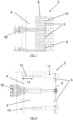
- the present invention relates to a new wall structure 2 for a vertical bright annealing furnace 1.
- This specific structure comprises a stack of insulating polycrystalline fibre modules 3 as illustrated by Figures 3 to 6 . Once the modules 3 are assembled and fixed to form the wall 2, an additional fibre blanket 4 can be added in the furnace 1 between the polycrystalline fibre modules 3 and the casing.
- Each module 3 has preferably a thickness between 400 and 500 mm, and more preferably of 450 mm.
- the additional fibre blanket 4 has preferably a thickness between 20 and 50mm, and more preferably of 25 mm.
- the insulating polycrystalline fibre modules 3 preferably comprise fibre with at least 95-97% of Al 2 O 3 .
- electric heating elements 6 are provided inside the furnace 1.
- the heating elements 6 are fixed to the modules 3 by an anchoring system 5.
- graphite lintels 11 are provided, preferably provided with chicanes.
- Graphite lintels 11 are fixed in the wall 2 between and/or within modules 3, and are cantilevered just above each heating element 6 (see Figures 6 and 8 ). This is more detailed in the following sections of the description.
- the wall 2 obtained with the modules 3 of the present invention exhibits an improved thermal insulation and thermal inertia offering a more flexible furnace temperature.
- This new solution will give the opportunity to have a wall lighter and easier to build, with no risk of cracks or fire in operation.
- Polycrystalline fibre modules 3 of the present invention can be for example a polycrystalline Saffil ® M-Fil prefabricated modules (source: Unifrax documentation).
- Saffil ® M-Fil modules 3 are manufactured from polycrystalline wool into a standard edge-stacked construction format. The modules are made of fibre compressed with cardboard (ou wooden) side plates with banding straps. These prefabricated modules 3 are specifically designed to meet the thermal insulation requirements of industrial furnaces.
- Saffil modules can be produced with various anchoring systems 14, 16, known per se of the skilled person and often commercially available, to enable quick, easy and efficient installation for most lining applications.
- polycrystalline alumina fibre modules can be replaced by a stack of graphite rigid felt boards 7, preferably horizontally arranged.
- This material has a carbon content of 99.5% and is very light (bulk density of about 0.2 g/cm 3 ).
- Polycrystalline fibre modules and heating elements assembly and anchoring method
- Polycrystalline fibre modules 3 according to the present invention can be assembled and fixed according different fixing methods known from prior art (see for example Unifrax documentation).
- RX2 anchoring system is a patented metal support in 321 stainless steel, which provides rapid attachment of the module 3 to the furnace casing via the external side fastener which is screwed onto a pre-welded stud. Rail, washer, nut, stud and ceramic arc shield are supplied (see US 2005/055940 A1 , ref. 14, 15, 18).
- Thread Lock (TL) anchoring system 14 and illustrated in Figure 11 , is attached to the furnace casing 15 by a central anchor in 304 stainless steel. Threaded studs 16 are pre-welded on the internal side of the furnace casing and the module anchor 14 is screwed on the stud by using a tool 20 such as a ratchet drive.
- the module anchor 14 has two wings terminated each with a hole 17 for supporting an assembly tube or rod linked in the same manner to adjacent module anchors.
- TL anchoring system has been especially designed for three reasons:
- shield bricks 10 containing 99% Al 2 O 3 are provided to protect the heating elements 6.
- These shield bricks are easy to implement, because they are refractory bricks 8 being placed so that they protrude inside the furnace 1, just above the vertical heating elements 6. In this manner, the travelling strip is prevented to hit the heating elements 6 being below the shield bricks 10.
- the fibre modules 3 per se do not allow to protect the heating elements 6 while forming the walls 2 of the furnace 1. Another shielding solution is therefore needed.
- Graphite lintels 11 can be advantageously obtained from machinable extruded graphite.
- Graphite is dense, has high temperature resistance and does not react with hydrogen. See example of data sheet below (mechanical data : "with the grain") : Bulk density g /cm3 1.7 Open porosity % 17 Young modulus GPa 10 Flexural strength MPa 18 Compressive strength MPa 39 Tensile strength Mpa 13
- the graphite lintels 11 advantageously protrude from a vertical wall line inside the furnace 1 to protect the heating elements 6. Additionally, the graphite lintels 11 have also the function of supporting and guiding the heating elements 6, via an anchoring system 5, for example under the form of molybdenum hooks.
- the heating elements 6 are preferably electric heating elements arranged according to a planar serpentine connected at each of its two ends to an insulated connector 30 going through the wall lining 2 and the external casing 15 of the furnace 1 to the power supply.
- the graphite lintels 11 are arranged in horizontal rows and are provided with anchoring system 5 made of vertical hooks, preferably made of molybdenum, so that adjacent vertical hooks located in two vertically adjacent lintel rows are respectively supporting the lower and upper successive loops of the heating element.
- supporting tubes 12 are welded to the casing 15 of the furnace in order to support the graphite lintels 11 in the insulation assembly. Further, a space 13 is provided between the back of the lintel 11 and the casing 15 of the furnace. This space 13 encloses the tube 12 supporting the lintel 11, and can be filled with bulk fibres known per se of the skilled person.
- the wall lining 2 comprises boards of graphite rigid felt, said boards are supported by the horizontal layers of graphite lintels 11 and attached to the casing with usual anchoring means (such as for bricks).
- Such as polycrystalline alumina fibre modules, graphite lintels 11 do not have the defects of the shield bricks 10 of prior art, such as cracks or breaks prone to occur in the bricks, possibly leading to pieces of brick and dust falling in the vertical furnace, and possibly damaging the strip or causing fire at the outlet of the furnace.
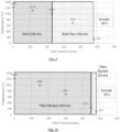
- the performances of the polycrystalline fibre modules 3 of the present invention are compared to the stack of casing modules of prior art, comprising refractory bricks and additional insulation.
- the results are illustrated in Figure 9 representing the temperature distribution in the thickness of a wall of the vertical bright annealing furnace of prior art, and in Figure 10 representing the temperature distribution in the thickness of a wall of the bright annealing furnace with the structure of the present invention.
- the wall of the bright annealing furnace of prior art comprises stack of casing modules with refractory bricks 8 and additional insulation 9 (made of bulk fibres).
- the wall of a bright annealing furnace according to the present invention comprises a structure with polycrystalline fibre modules 3 having a thickness of 450 mm and an additional fibre blanket (backup layer faced with aluminium foil, e.g. Insulfrax ® S blanket, documentation Unifrax) having a thickness of 25 mm.
- the external casing temperature of the furnace is 132°C, leading to a thermal flux of 1460 W/m2.
- the external casing temperature of the furnace is 115°C, leading to a thermal flux of 1122 W/m2.
- the lining of the furnace walls in the present invention allows a reduction of external casing temperature of 17°C and of thermal flux of 23%.
Landscapes
- Chemical & Material Sciences (AREA)
- Engineering & Computer Science (AREA)
- Mechanical Engineering (AREA)
- Physics & Mathematics (AREA)
- Thermal Sciences (AREA)
- Crystallography & Structural Chemistry (AREA)
- Materials Engineering (AREA)
- Metallurgy (AREA)
- Organic Chemistry (AREA)
- General Engineering & Computer Science (AREA)
- Ceramic Engineering (AREA)
- Furnace Housings, Linings, Walls, And Ceilings (AREA)
Priority Applications (8)
| Application Number | Priority Date | Filing Date | Title |
|---|---|---|---|
| EP22157736.4A EP4230940A1 (de) | 2022-02-21 | 2022-02-21 | Hochleistungswärmedämmung eines wärmebehandlungsofens zum glühen eines kontinuierlich laufenden bandes |
| CA3250049A CA3250049A1 (en) | 2022-02-21 | 2023-02-15 | HIGH-PERFORMANCE THERMAL INSULATION OF A HEAT TREATMENT OVEN FOR ANNEALING A CONTINUOUSLY MOVING BELD |
| EP23704186.8A EP4483115A1 (de) | 2022-02-21 | 2023-02-15 | Hochleistungs-wärmeisolierung eines wärmebehandlungsofens zum glühen eines kontinuierlich bewegten bandes |
| KR1020247022707A KR20240153972A (ko) | 2022-02-21 | 2023-02-15 | 연속적으로 이동하는 스트립의 어닐링을 위한 열처리 용광로의 고성능 단열재 |
| US18/839,446 US20250163534A1 (en) | 2022-02-21 | 2023-02-15 | High performance thermal insulation of a heat treatment furnace for annealing a continuously moving strip |
| CN202380016976.5A CN118541578A (zh) | 2022-02-21 | 2023-02-15 | 用于对连续移动的条带进行退火的热处理炉的高性能隔热 |
| PCT/EP2023/053691 WO2023156418A1 (en) | 2022-02-21 | 2023-02-15 | High performance thermal insulation of a heat treatment furnace for annealing a continuously moving strip |
| ZA2024/05494A ZA202405494B (en) | 2022-02-21 | 2024-07-15 | High performance thermal insulation of a heat treatment furnace for annealing a continuously moving strip |
Applications Claiming Priority (1)
| Application Number | Priority Date | Filing Date | Title |
|---|---|---|---|
| EP22157736.4A EP4230940A1 (de) | 2022-02-21 | 2022-02-21 | Hochleistungswärmedämmung eines wärmebehandlungsofens zum glühen eines kontinuierlich laufenden bandes |
Publications (1)
| Publication Number | Publication Date |
|---|---|
| EP4230940A1 true EP4230940A1 (de) | 2023-08-23 |
Family
ID=80628507
Family Applications (2)
| Application Number | Title | Priority Date | Filing Date |
|---|---|---|---|
| EP22157736.4A Withdrawn EP4230940A1 (de) | 2022-02-21 | 2022-02-21 | Hochleistungswärmedämmung eines wärmebehandlungsofens zum glühen eines kontinuierlich laufenden bandes |
| EP23704186.8A Pending EP4483115A1 (de) | 2022-02-21 | 2023-02-15 | Hochleistungs-wärmeisolierung eines wärmebehandlungsofens zum glühen eines kontinuierlich bewegten bandes |
Family Applications After (1)
| Application Number | Title | Priority Date | Filing Date |
|---|---|---|---|
| EP23704186.8A Pending EP4483115A1 (de) | 2022-02-21 | 2023-02-15 | Hochleistungs-wärmeisolierung eines wärmebehandlungsofens zum glühen eines kontinuierlich bewegten bandes |
Country Status (7)
| Country | Link |
|---|---|
| US (1) | US20250163534A1 (de) |
| EP (2) | EP4230940A1 (de) |
| KR (1) | KR20240153972A (de) |
| CN (1) | CN118541578A (de) |
| CA (1) | CA3250049A1 (de) |
| WO (1) | WO2023156418A1 (de) |
| ZA (1) | ZA202405494B (de) |
Families Citing this family (1)
| Publication number | Priority date | Publication date | Assignee | Title |
|---|---|---|---|---|
| CN120738455B (zh) * | 2025-09-02 | 2026-01-06 | 江苏甬金金属科技有限公司 | 一种附带全纤维结构的立式光亮退火炉 |
Citations (8)
| Publication number | Priority date | Publication date | Assignee | Title |
|---|---|---|---|---|
| US4088825A (en) * | 1976-08-04 | 1978-05-09 | General Electric Company | Electric furnace wall construction |
| EP0052840A1 (de) * | 1980-11-24 | 1982-06-02 | Kennecott Corporation | Halterungsanlage oder Abstützung für elektrische Heizelemente in Öfen oder Einrichtungen, die mit keramischen Fasern isoliert sind |
| US4341916A (en) * | 1980-10-30 | 1982-07-27 | Manville Service Corporation | Electric furnace insulation module |
| US4486888A (en) * | 1981-08-17 | 1984-12-04 | Sevink Theodor J | Furnace, especially a ceramic or heating furnace |
| US4489920A (en) * | 1983-05-20 | 1984-12-25 | Jones William R | Hot zone chamber wall arrangement for use in vacuum furnaces |
| US20050055940A1 (en) | 1998-07-24 | 2005-03-17 | F.C.S. Dixon Limited | Furnace lining |
| CN203336969U (zh) * | 2013-05-28 | 2013-12-11 | 武汉钢铁(集团)公司 | 全纤维节能炉衬外罩 |
| CN109341353A (zh) * | 2018-09-28 | 2019-02-15 | 武汉钢铁有限公司 | 热轧加热炉低散热炉衬结构 |
-
2022
- 2022-02-21 EP EP22157736.4A patent/EP4230940A1/de not_active Withdrawn
-
2023
- 2023-02-15 EP EP23704186.8A patent/EP4483115A1/de active Pending
- 2023-02-15 CN CN202380016976.5A patent/CN118541578A/zh active Pending
- 2023-02-15 WO PCT/EP2023/053691 patent/WO2023156418A1/en not_active Ceased
- 2023-02-15 CA CA3250049A patent/CA3250049A1/en active Pending
- 2023-02-15 KR KR1020247022707A patent/KR20240153972A/ko active Pending
- 2023-02-15 US US18/839,446 patent/US20250163534A1/en active Pending
-
2024
- 2024-07-15 ZA ZA2024/05494A patent/ZA202405494B/en unknown
Patent Citations (8)
| Publication number | Priority date | Publication date | Assignee | Title |
|---|---|---|---|---|
| US4088825A (en) * | 1976-08-04 | 1978-05-09 | General Electric Company | Electric furnace wall construction |
| US4341916A (en) * | 1980-10-30 | 1982-07-27 | Manville Service Corporation | Electric furnace insulation module |
| EP0052840A1 (de) * | 1980-11-24 | 1982-06-02 | Kennecott Corporation | Halterungsanlage oder Abstützung für elektrische Heizelemente in Öfen oder Einrichtungen, die mit keramischen Fasern isoliert sind |
| US4486888A (en) * | 1981-08-17 | 1984-12-04 | Sevink Theodor J | Furnace, especially a ceramic or heating furnace |
| US4489920A (en) * | 1983-05-20 | 1984-12-25 | Jones William R | Hot zone chamber wall arrangement for use in vacuum furnaces |
| US20050055940A1 (en) | 1998-07-24 | 2005-03-17 | F.C.S. Dixon Limited | Furnace lining |
| CN203336969U (zh) * | 2013-05-28 | 2013-12-11 | 武汉钢铁(集团)公司 | 全纤维节能炉衬外罩 |
| CN109341353A (zh) * | 2018-09-28 | 2019-02-15 | 武汉钢铁有限公司 | 热轧加热炉低散热炉衬结构 |
Also Published As
| Publication number | Publication date |
|---|---|
| EP4483115A1 (de) | 2025-01-01 |
| CA3250049A1 (en) | 2023-08-24 |
| WO2023156418A1 (en) | 2023-08-24 |
| KR20240153972A (ko) | 2024-10-24 |
| US20250163534A1 (en) | 2025-05-22 |
| ZA202405494B (en) | 2025-12-17 |
| CN118541578A (zh) | 2024-08-23 |
Similar Documents
| Publication | Publication Date | Title |
|---|---|---|
| US4246852A (en) | Industrial furnace with ceramic insulating modules | |
| EP2952844B1 (de) | Monolithische feuerfeste struktur | |
| KR20160024845A (ko) | 다중 층 냉각 패널 및 전기 아크로 | |
| EP4230940A1 (de) | Hochleistungswärmedämmung eines wärmebehandlungsofens zum glühen eines kontinuierlich laufenden bandes | |
| EP0097482A1 (de) | Feuerfeste Überzüge zur Anwendung bei Transporteinrichtungen für Fluide | |
| JPH02116635A (ja) | 加熱容器の耐火物被覆蓋 | |
| JP2000248305A (ja) | ステーブクーラー | |
| US3820947A (en) | Insulation for water cooled pipes in a reheating furnace | |
| US4290457A (en) | Truncated triangular insulator | |
| US4704155A (en) | Heating vessel lid construction for a glass melting furnace | |
| WO2010131213A1 (en) | Refractory lining of cooled pipes | |
| CN117287979A (zh) | 一种全纤维复合炉顶结构 | |
| JP3040208B2 (ja) | 焼成炉の炉壁装置 | |
| KR100833000B1 (ko) | 열팽창에 의한 내화물 파손이 방지되는 래들 | |
| JP2765449B2 (ja) | 高炉炉体冷却装置 | |
| JP2007240053A (ja) | 雰囲気炉の吊り天井構造 | |
| JP2757751B2 (ja) | 竪形マツフル炉 | |
| JP2524669B2 (ja) | 連続鋼片加熱炉 | |
| JP2008045816A (ja) | 焼成炉炉体構造 | |
| JPH0432689A (ja) | 工業窯炉天井の構造とその施工方法 | |
| JPS6236847Y2 (de) | ||
| CN210036276U (zh) | 一种高温炉窑复合耐火纤维模块 | |
| JPH0718651B2 (ja) | 耐熱ブロツク | |
| JPH07280456A (ja) | 炉壁構造 | |
| JPS63150578A (ja) | 窯炉断熱ライニング方法 |
Legal Events
| Date | Code | Title | Description |
|---|---|---|---|
| PUAI | Public reference made under article 153(3) epc to a published international application that has entered the european phase |
Free format text: ORIGINAL CODE: 0009012 |
|
| STAA | Information on the status of an ep patent application or granted ep patent |
Free format text: STATUS: THE APPLICATION HAS BEEN PUBLISHED |
|
| AK | Designated contracting states |
Kind code of ref document: A1 Designated state(s): AL AT BE BG CH CY CZ DE DK EE ES FI FR GB GR HR HU IE IS IT LI LT LU LV MC MK MT NL NO PL PT RO RS SE SI SK SM TR |
|
| 18D | Application deemed to be withdrawn |
Effective date: 20240224 |