EP4231032B1 - Cellule à vapeur atomique, dispositif atomique/photonique intégré et appareil comprenant la cellule à vapeur atomique et procédé de fabrication d'une cellule à vapeur atomique - Google Patents
Cellule à vapeur atomique, dispositif atomique/photonique intégré et appareil comprenant la cellule à vapeur atomique et procédé de fabrication d'une cellule à vapeur atomique Download PDFInfo
- Publication number
- EP4231032B1 EP4231032B1 EP22382127.3A EP22382127A EP4231032B1 EP 4231032 B1 EP4231032 B1 EP 4231032B1 EP 22382127 A EP22382127 A EP 22382127A EP 4231032 B1 EP4231032 B1 EP 4231032B1
- Authority
- EP
- European Patent Office
- Prior art keywords
- atomic
- chamber
- host substrate
- reservoir
- atomic vapor
- Prior art date
- Legal status (The legal status is an assumption and is not a legal conclusion. Google has not performed a legal analysis and makes no representation as to the accuracy of the status listed.)
- Active
Links
Images


Classifications
-
- B—PERFORMING OPERATIONS; TRANSPORTING
- B81—MICROSTRUCTURAL TECHNOLOGY
- B81B—MICROSTRUCTURAL DEVICES OR SYSTEMS, e.g. MICROMECHANICAL DEVICES
- B81B1/00—Devices without movable or flexible elements, e.g. microcapillary devices
-
- G—PHYSICS
- G01—MEASURING; TESTING
- G01R—MEASURING ELECTRIC VARIABLES; MEASURING MAGNETIC VARIABLES
- G01R33/00—Arrangements or instruments for measuring magnetic variables
- G01R33/20—Arrangements or instruments for measuring magnetic variables involving magnetic resonance
- G01R33/24—Arrangements or instruments for measuring magnetic variables involving magnetic resonance for measuring direction or magnitude of magnetic fields or magnetic flux
- G01R33/26—Arrangements or instruments for measuring magnetic variables involving magnetic resonance for measuring direction or magnitude of magnetic fields or magnetic flux using optical pumping
-
- B—PERFORMING OPERATIONS; TRANSPORTING
- B81—MICROSTRUCTURAL TECHNOLOGY
- B81B—MICROSTRUCTURAL DEVICES OR SYSTEMS, e.g. MICROMECHANICAL DEVICES
- B81B7/00—Microstructural systems ; Auxiliary parts of microstructural devices or systems
- B81B7/02—Microstructural systems ; Auxiliary parts of microstructural devices or systems containing distinct electrical or optical devices of particular relevance for their function, e.g. microelectro-mechanical systems [MEMS]
-
- B—PERFORMING OPERATIONS; TRANSPORTING
- B81—MICROSTRUCTURAL TECHNOLOGY
- B81C—PROCESSES OR APPARATUS SPECIALLY ADAPTED FOR THE MANUFACTURE OR TREATMENT OF MICROSTRUCTURAL DEVICES OR SYSTEMS
- B81C1/00—Manufacture or treatment of devices or systems in or on a substrate
- B81C1/00015—Manufacture or treatment of devices or systems in or on a substrate for manufacturing microsystems
- B81C1/00023—Manufacture or treatment of devices or systems in or on a substrate for manufacturing microsystems without movable or flexible elements
- B81C1/00047—Cavities
-
- G—PHYSICS
- G01—MEASURING; TESTING
- G01R—MEASURING ELECTRIC VARIABLES; MEASURING MAGNETIC VARIABLES
- G01R33/00—Arrangements or instruments for measuring magnetic variables
- G01R33/0052—Manufacturing aspects; Manufacturing of single devices, i.e. of semiconductor magnetic sensor chips
-
- G—PHYSICS
- G01—MEASURING; TESTING
- G01R—MEASURING ELECTRIC VARIABLES; MEASURING MAGNETIC VARIABLES
- G01R33/00—Arrangements or instruments for measuring magnetic variables
- G01R33/02—Measuring direction or magnitude of magnetic fields or magnetic flux
- G01R33/032—Measuring direction or magnitude of magnetic fields or magnetic flux using magneto-optic devices, e.g. Faraday or Cotton-Mouton effect
-
- G—PHYSICS
- G01—MEASURING; TESTING
- G01R—MEASURING ELECTRIC VARIABLES; MEASURING MAGNETIC VARIABLES
- G01R33/00—Arrangements or instruments for measuring magnetic variables
- G01R33/20—Arrangements or instruments for measuring magnetic variables involving magnetic resonance
- G01R33/44—Arrangements or instruments for measuring magnetic variables involving magnetic resonance using nuclear magnetic resonance [NMR]
- G01R33/46—NMR spectroscopy
-
- G—PHYSICS
- G04—HOROLOGY
- G04F—TIME-INTERVAL MEASURING
- G04F5/00—Apparatus for producing preselected time intervals for use as timing standards
- G04F5/14—Apparatus for producing preselected time intervals for use as timing standards using atomic clocks
-
- G—PHYSICS
- G04—HOROLOGY
- G04F—TIME-INTERVAL MEASURING
- G04F5/00—Apparatus for producing preselected time intervals for use as timing standards
- G04F5/14—Apparatus for producing preselected time intervals for use as timing standards using atomic clocks
- G04F5/145—Apparatus for producing preselected time intervals for use as timing standards using atomic clocks using Coherent Population Trapping
-
- G—PHYSICS
- G01—MEASURING; TESTING
- G01N—INVESTIGATING OR ANALYSING MATERIALS BY DETERMINING THEIR CHEMICAL OR PHYSICAL PROPERTIES
- G01N24/00—Investigating or analyzing materials by the use of nuclear magnetic resonance, electron paramagnetic resonance or other spin effects
- G01N24/006—Investigating or analyzing materials by the use of nuclear magnetic resonance, electron paramagnetic resonance or other spin effects using optical pumping
Definitions
- the present invention generally relates, in a first aspect, to an atomic vapor cell, for atomic or molecular spectroscopy, optical pumping (for sensing or non-sensing applications) and/or spin-based atomic sensing, and particularly to an atomic vapor cell comprising a laser written buried or non-buried chamber with either planar or three-dimensional geometry.
- a second aspect of the present invention relates to an integrated atomic/photonic device, comprising the atomic vapor cell of the first aspect.
- a third aspect of the present invention relates to an apparatus, comprising the atomic vapor cell of the first aspect and/or the integrated atomic/photonic device of the second aspect.
- a fourth aspect of the present invention relates to a method for fabricating the atomic vapor cell of the first aspect, for atomic or molecular spectroscopy, optical pumping and/or spin-based atomic sensing.
- An atomic vapor cell for atomic or molecular spectroscopy, optical pumping and/or spin-based atomic sensing, including the features defined in the preamble of claim 1 Is known in the prior art, i.e., a cell comprising a host substrate and defined there within a chamber for containing an atomic vapor.
- vapor cells suffer from different drawbacks or limitations such as, but not only, the planar geometry of the chambers or surface microchannels, which cannot be fabricated at a desired depth and size in three dimensions, or the need of using masks or photoresists, or the lack of freedom for the selection of the host material, particularly of the need of including non-transparent walls and thus limit the locations and quantity of optical accesses enabled thereby.
- the present invention relates, in a first aspect, to an atomic vapor cell, for atomic or molecular spectroscopy, optical pumping and/or spin-based atomic sensing, comprising a host substrate and defined there within a chamber for containing an atomic
- the atomic vapor cell in accordance with the invention is defined in claim 1.
- the chamber is a buried or non-buried chamber with either planar or three-dimensional geometry, laser written in the host substrate, i.e., without the need of a mask or photoresist.
- the host substrate and chamber are configured and arranged to enable multiple optical access to an atomic interaction area of the chamber along at least two optical axes.
- the atomic vapor cell of the first aspect of the present invention further comprises, also laser written in the host substrate, a buried or non-buried reservoir and connecting channels fluidically communicating the chamber with the reservoir, wherein the reservoir is a planar or three-dimensional reservoir.
- the reservoir has at least one open end defined at a face of the host substrate and the vapor cell further comprises a sealing substrate bonded to said face of the host substrate to seal said at least one open end, wherein said at least one open end was made to remove excess material from the laser writing process therethrough and to fill the reservoir with said atomic vapor or with a source of material originating said atomic vapor.
- the chamber comprises at least an inlet connection to fill the same with the atomic vapor from the exterior of the atomic vapor cell, and, for a variant of that embodiment, also an outlet connection to make the atomic vapor enter the chamber through the input connection, flow through the chamber, and exit the chamber through the outlet connection.
- At least the host substrate is transparent to a determined wavelength of a light beam used for a single or multiple optical access to the chamber for performing the above mentioned atomic or molecular spectroscopy, optical pumping, and/or spin-based atomic sensing.
- the chamber has at least a pair of respective opposite ends adjacent to respective opposite side facets of the host substrate, so that optical access along one dimension of the chamber is enabled for a light beam entering the chamber through one of said opposite ends and exits the same through the other of said opposite ends.
- the chamber has at least two pairs of respective opposite ends adjacent to respective opposite side facets of pairs of opposite side facets of the host substrate, so that multiple optical access along two respective transversal dimensions of the chamber is enabled for two respective light beams, each entering the chamber through one of the opposite ends of a respective pair and exits the same through the other of said opposite ends.
- the chamber for example, a cubic-shaped chamber
- the chamber has three pairs of respective opposite ends adjacent to respective opposite side facets of pairs of opposite side facets of the host substrate, so that multiple optical access along three respective transversal dimensions of the chamber is enabled for three respective light beams, each entering the chamber through one of the opposite ends of a respective pair and exits the same through the other of said opposite ends.
- the reservoir and the chamber further contain a buffer gas and/or are internally treated with the addition of a diffusion barrier to prevent atomic depolarizing collisions.
- This treatment is, for an implementation of that embodiment, a deposition of nanolayers (one or more layers with a thickness of tens of nanometers) of a non-depolarizing material, like aluminum oxide, onto the non-buried laser written chambers.
- the atomic vapor cell comprises a plurality of planar or three-dimensional chambers, fabricated like the one described above, with the same or a different shape (elongate shape, prismatic shape, etc.), and/or one or more buried or non-buried laser written chambers, where non-fluidically connected to each other, or some or all of them fluidically connected with each other, depending on the embodiment.
- the present invention also relates, in a second aspect, to an integrated atomic/photonic device, comprising the atomic vapor cell of the first aspect and at least one further photonic component defined or arranged on the host substrate or on a further host substrate.
- the at least one further photonic component is either a planar or non-planar waveguide-based photonic component laser written in the host substrate or in the further host substrate, or placed in a slot laser written in the host substrate or in the further host substrate.
- planar and/or non-planar waveguide-based photonic components are included in the integrated atomic/photonic device of the second aspect of the present invention: a linear waveguide, a waveplate waveguide, a beam splitter waveguide, and optical components like microlenses, e.g., GRIN (Gradient-Index) lenses, etc., or a combination thereof.
- GRIN Gradient-Index
- the present invention relates to an apparatus, comprising the atomic vapor cell of the first aspect and/or the integrated atomic/photonic device of the second aspect.
- the apparatus is at least one of the following apparatuses: a system for saturated absorption spectroscopy (SAS), an atomic spectroscopy/frequency reference, an atomic clock, a single-beam or two beams optically-pumped-magnetometer, a magnetic microscope, a spin-based atomic sensor, and an atomic gyroscope.
- SAS saturated absorption spectroscopy
- atomic spectroscopy/frequency reference an atomic clock
- a single-beam or two beams optically-pumped-magnetometer a magnetic microscope
- a spin-based atomic sensor a spin-based atomic sensor
- an atomic gyroscope an atomic gyroscope
- the apparatus of the third aspect of the present invention further comprises optical fibres joint/glued to the vapor cell or to the atomic/photonic device so that laser light of one or multiple laser beams can input through at least one of said optical fibres, propagate through the chamber, and then output therefrom, after atomic interaction, though at least one other of said optical fibres.
- the method of the fourth aspect of the present invention is adapted, for an embodiment, to fabricate the atomic vapor cell of the first aspect of the present invention.
- the method of the fourth aspect of the present invention further comprises:
- the atomic vapor cell comprises a chamber 102, a reservoir 103 and connecting channels 104 which are directly-written by laser-irradiation (with laser source L, represented in the left-top view) on a solid host material or substrate 101 in a non-planar geometry.
- the chamber 102, the reservoir 103 and the connecting channels 104 are empty since the substrate material is removed in a second step after irradiation, for example through immersion in a chemical etchant solution.
- the solid host substrate 101 is made of a transparent material like fused silica or borofloat in a preferred embodiment, but it is made of a different material, such as silicon nitride, ceramics, crystals, and polymers, in other embodiments. While, for the illustrated embodiments, the chamber 102 and the connecting channels 104 are completely buried within the host material, the reservoir 103 reaches an open facet or open end, in order to remove material, e.g., with a chemical etchant, and to fill the cell.
- the reservoir 103 is at a different depth with respect to the chamber 102, while, for another embodiment, such as that of the three bottom views of Figure 1 , the reservoir 103b is at a side of the chamber 102.
- chamber 102, connecting channels 104 and reservoir 103 are laser written in a planar non-buried configuration on the top surface of the solid host substrate 101.
- the cell is then filled with a source of evaporable material 1104 that is a solid state dispenser in one embodiment, a liquid solution containing alkali metal, e.g., alkali-metal azide in another embodiment, and pure alkali metal in another embodiment.
- a source of evaporable material 1104 that is a solid state dispenser in one embodiment, a liquid solution containing alkali metal, e.g., alkali-metal azide in another embodiment, and pure alkali metal in another embodiment.
- the reservoir 103, 103b is filled with the evaporable material 1104 through its respective open end, and the evaporable material 1104 reaches the chamber 102 by diffusion, as shown by the cloud of points represented in the right, top and bottom, views of Figure 1 .
- sealing substrate 105 covers the whole bottom face of the host substrate 104, while sealing substrate 105b is disc-shaped and covers only the open end of the reservoir 103b.
- any of those sealing substrates 105, 105b has a different shape than that illustrated and/or cover only the open end of the reservoir 103, 103b, or partly or completely the face of the host substrate 104 reached by that open end.
- the bonding of the sealing substrate 105, 105b occurs with UV curing glue, while in another embodiment the bonding consists in glass-to-glass bonding, e.g., optical contact bonding, or glass-silicon-glass bonding.
- the evaporable material or compound 1104 contains alkali metals like rubidium, cesium, or potassium, in natural abundance, in an embodiment, or pure isotopes in another embodiment. These are released with an activation process after bonding, like UV reaction in one embodiment, or laser activation in another embodiment.
- the filling of the dispenser 1104 occurs in vacuum chambers or with addition of noble gases as buffer gas (with pressures higher than 100 Torr) to prevent atomic depolarizing collisions, like nitrogen in one embodiment or mixture of nitrogen and argon in another embodiment, or other noble gases like 3 He and 129 Xe in another embodiment, depending on the sensing and spectroscopy application.
- noble gases like buffer gas (with pressures higher than 100 Torr) to prevent atomic depolarizing collisions, like nitrogen in one embodiment or mixture of nitrogen and argon in another embodiment, or other noble gases like 3 He and 129 Xe in another embodiment, depending on the sensing and spectroscopy application.
- the atomic vapor or compound continuously diffuses through inlet and outlet connections, like in lab-on-chip microfluidics, into the written chamber(s) 102, which are heated at temperature above 80 C.
- the reservoir 103, 103b is connected to a glass system and filled with glassblowing techniques before sealing.
- FIG. 2 different views of the LWVC of the present invention are shown, illustrating LWVCs exemplary dimensions, for different embodiments. Particularly, an embodiment is represented by the three top views of the figure, another embodiment by the two left, middle and bottom, views of the figure, and two further embodiments by the middle and right bottom views of the figure.
- the direct laser-writing has 3D versatility so the chamber/channel 102 is, for an embodiment, buried within the host at depth 108/108b, i.e., distanced from the top facet of the host material substrate 101 (according to the depicted position), ranging from mm down to ten nanometres, depending on the application.
- the depth 108, 108b is, for an embodiment, the stand-off distance of the atomic sensor from a sample and it is, for an embodiment, reduced down to the nanometre scale.
- the distance from the cell wall 109/109b is, for an embodiment, minimized to reduce optical losses.
- the side facets are, for an embodiment, further polished to minimize transmission losses.
- the reservoir 103/103b can have a diameter 115, 115b as small as the evaporable source, and a height 112 as short as the same.
- SAES Getters commercial alkali metal dispensers
- micron-sized dispensers are, for an embodiment, produced so that the reservoir 103, 103b can have accordingly micron-sized diameter and height.
- Each of the outer dimensions 106, 107 of the host substrate 101 can vary from 1 cm in one embodiment to sub-mm size in another embodiment, depending on the application.
- the sealing substrate 105/105b can also have a thickness 113, 113b ranging from a few mm (where "few" means at least 2) down to tens or hundreds micron.
- the connecting channels 104 can have a cross section down to tens of micron and variable length 111 and shape to connect reservoir 103, 103b and chamber 102.
- the chamber 102 is a squared or cylindrical channel in two different embodiments, although any other kind of non-planar shape is also possible, for other embodiments.
- Its cross section 110, 110b is 1 mm x 1 mm in one embodiment or having sub-mm dimension in another embodiment, e.g., 100 micron x 100 micron, where chamber(s) 102 are then microchannels.
- the chamber 102b is a cubic or cylindrical cavity with width 114b and thickness of few mm (where "few” means at least 1 mm), similarly to MEMS cells, to increase the atomic interaction volume and to reduce depolarizing collisions by the walls.
- a laser beam can then be collimated or focused into the microchannel/chamber 102, 102b, depending on its size and length.
- the length 114 is 1 cm in one preferred embodiment, but the length 114b is reduced to a mm side in another embodiment.
- the physics chamber i.e., the chamber 102
- the chamber 102 can actually be squared or cubic depending on double or triple optical access (not shown).
- the distance between the chamber 102 and the host side facet 116/116b, as well as the outer host substrate's dimension 107 and 107b is, for an embodiment, reduced to match reservoir 103, 103b and chamber 102, 102b dimensions to minimize the host substrate 101 total volume.
- FIG 3 schematically illustrates the device of the second aspect of the present invention, also called below LWVC device, for different embodiments, for free space probing and integration of LWVCs with photonic waveguides, optical components, fibres and, more generally, with any waveguide-based photonic structure in non-planar geometry.
- the LWVC is, for an embodiment, used with laser light in free space, as shown in the left view of Figure 3 where a laser beam 117 propagates along the channel/chamber 102 in the LWVC.
- the LWVC can otherwise be integrated with photonic waveguides 118 and 119 laser-written with the same technique on a separated host material in one embodiment, and in the same host substrate 101 of the LWVC in another embodiment.
- the input laser-written waveguide 118 is, for an embodiment, a polarization rotator that can polarize the input light beam circularly or linearly.
- the waveguide output directly propagates through the chamber 102 of the LWVC.
- the mode of the input waveguide 118 is, for an embodiment, expanded and collimated through an optical element 120 to the physics channel or chamber 102.
- the fibres are single-mode in an embodiment or multi-mode in another embodiment.
- the output fibre 123 is a fiberized mirror that reflects light back after atomic interaction, so that light is coupled back into the same input fibre 122 after double pass atomic interaction.
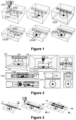
- Figure 6 shows SAS spectra for both the LWVC and the conventional reference cell. These resolve all sub-Doppler and crossover resonances for both 85Rb and 87Rb isotopes.
- SNR signal-to-noise ratio
- the present inventors performed measurements of zero-field magnetic resonance (ZFR) using an elliptically polarized single beam.
- the experimental setup is shown in the bottom view of Figure 5 .
- the laser beam is partially circularly polarized by a quarter-wave-plate QWV so that the atomic ensemble is optically-pumped with a non-zero electron spin polarization P Z along the z-axis.
- the linearly polarized component of the same beam undergoes paramagnetic Faraday self-rotation, which is detected by a polarimeter, consisting of a half-wave-plate HWP, a PBS and a differential photo-detector BPD with switchable gain (Thorlabs PDB450A).
- a polarimeter consisting of a half-wave-plate HWP, a PBS and a differential photo-detector BPD with switchable gain (Thorlabs PDB450A).
- a polarimeter consisting of a half-wave-plate HWP, a PBS and a differential photo-detector BPD with switchable gain (Thorlabs PDB450A).
- different DFB lasers were used at either 795 nm or 780 nm, tuned near the central D1 or D2 lines of 85Rb, respectively.
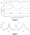
- Figures 7(a) and 7(b) show zero-field magnetic resonances for the D1 and D2 Rb lines when the transverse magnetic field B X is scanned over a range of about 100 ⁇ T.
- These experimental resonances demonstrate that optical pumping is, for an embodiment, performed in the laser-written atomic vapor cells (LWVCs) of the present invention, and that atomic sensors based on atomic spin coherence is, for an embodiment, realized with this manufacturing technique.
- views a) and b) show rotation signals versus transverse field for D2 and D1 lines, respectively, acquired with 3.5 mW of probe power.
- Solid lines show experimental data, dashed lines show prediction of Eq. (1) explained below.
- V. Shah et al "Spin-exchange relaxation-free magnetometry using elliptically polarized light," Phys. Rev. A 80, 013416 (2009 ).
- the LWVC of the present invention is, for an embodiment, used either with laser optics in free space, as described above, or integrated into the integrated atomic/photonic device of the second aspect of the invention, as described above, for several applications in atomic and molecular spectroscopy as well as for atomic quantum sensing.
- the integration with optical waveguides and fibres can enable a plug-and-play operation of the disclosed LWVCs.
- FIG. 8 top view, depicts a typical spectroscopy application where light from a laser source 135, near resonant with the atomic or molecular compound 104 in the reservoir 103 of the LWVC 134, is fibre coupled 137, propagates through the LWVC and it is detected with a photodetector 138 after atomic or molecular interaction.
- the LWVC device is heated with a heater element 134b to reach the desired density of the evaporable source 104.
- the heater 134b is, for an embodiment, a Kapton adhesive underneath the LWVC in one embodiment, a bonded resistive serpentine in another embodiment or a transparent ITO heater in yet another embodiment, where it could be used to close bond the reservoir 103 too.
- the LWVC is, for an embodiment, heated by hot air or with fiberized light heaters. If the laser source is scanned with an appropriate modulation controller 136, an absorption spectrum is detected at 138. In another embodiment light can propagate in free space through the laser-written atomic/molecular channel/interaction area.
- a different application is shown, particularly an application of the LWVC device for laser frequency stabilization.
- the transmitted beam is reflected back with a planar mirror 139 and does not change its polarization by double pass in a quarter-wave-plate (QWP) 140, as described in the SAS experiments described above.
- QWP quarter-wave-plate
- Light is coupled back into the LWVC after reflection and, after double pass through the LWVC, is detected with a photodiode 138b.
- the laser 135 current or phase is, for an embodiment, modulated with a local oscillator 143 so that the saturated-absorption-spectroscopy signal is, for an embodiment, demodulated at the same frequency to get an error signal, e.g., with a Pound-Drever-Hall (PDH) circuit 141 and a Servo system 142 is used to give feedback to the laser 135 to stabilize its frequency.
- the laser power is, for an embodiment, adjusted with a half-waveplate 144 and a polarizing beam splitter 145.
- the reflection mirror 139 is fiberized and the QWP 140 integrated in the device.
- anti-reflection coating is applied to one side of the LWVC to reflect back the transmitted light.
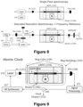
- FIG 9 depicts an application of a LWVC 134 for a chip-scale atomic clock.
- a coherence population trapping (CPT) atomic clock is shown.
- the frequency of a laser source 135 is modulated with a RF Synthesizer 147 at frequency given by a main local oscillator 146.
- a longitudinal magnetic field is generated with magnetic coils 148 and the system is enclosed in a magnetic shielding 149.
- Laser light is fibre coupled (FC 137) into the waveguide written in the LWVC and the optical mode is expanded and collimated with elements 118 and 120, as described above with reference to Figure 3 .
- the laser light is, for an embodiment, circularly polarized before the fibre or the waveguide 118, for example with a polarization rotator, a quarter waveplate 150 for the illustrated embodiment, or another polarization element for another embodiment (not shown).
- the LWVC device is, for an embodiment, heated with a heater element 134b to reach the desired density of the atomic ensemble/compound.
- a microwave cavity generates the atomic coherence instead of laser modulation.
- light can propagate in free space through the laser-written chambers.
- FIG 10 top view, depicts the application of a LWVC 134 for an optically-pumped-magnetometer (OPM), apart from the single beam scheme in free space, demonstrated above with reference to Figure 7 .
- OPM optically-pumped-magnetometer
- a resonant pump laser 154 modulated at frequency given by a local oscillator 156) and a near-resonance probe laser 153 are coupled into the same optical mode 155 and to the LWVC input waveguide.
- An integrated waveguide-based element 118/157 e.g., a multi-order waveplate, circularly polarize the pump beam while keeping linearly polarized the probe beam light.
- the LWVC device is heated with a heater element 134b to reach the desired density of the atomic ensemble/compound 104.
- Atomic polarization is generated in the LWVC sensing channel/chamber 102 by optical pumping.
- the atomic spins precess at Larmor frequency. This precession translates into paramagnetic Faraday rotation for the probe light, whose output is fiber coupled (158), spectrally filtered to block the pump light by an interference filter (159) and detected through a balanced polarimeter, which consists of a half-waveplate 160, a polarizing beam splitter 160b, two photodiodes 161/161b and a transimpedance amplifier 162.
- the differential rotation signal is processed with a data acquisition system (magnetic signal processing unit 163) and the Larmor frequency is extracted to give the magnetic field magnitude.
- the magnetic signal processing consists in frequency counters that do not need calibration.
- a cross configuration with pump and probe beam mutually orthogonal are used, with a LWVC described in Fig. 11 below.
- one pump beam and two probe beams interact with the same laser-written interaction area to give a vector magnetometer.
- three LWVCs are combined with orthogonal channels orientation, to give a 3-axis vector magnetometer.
- a magnetic sample is placed on the top facet of the LWVC 134.
- the magnetic sample 164 is placed in a microfluidic channel with inlet 164a and outlet 164b within the same material hosting the LWVC. This sample is, for an embodiment, a biological, liquid or an organ-on-chip that generates electromagnetic signals.
- the magnetic microscope depicted in the bottom view Figure 10 One particular application of OPMs using LWVCs and microchannels is the magnetic microscope depicted in the bottom view Figure 10 .
- the magnetic sample 164 that is, for an embodiment, biological or a material, is placed at stand-off distance D 167 from the laser-written microchannels, i.e., from the chamber(s) 102. D can go down to nanometre scale, so that the atomic sensor gets very close to the sample 164.
- the LWVC is used as an OPM, to give information about the magnetic field with sub-mm spatial resolution at 163 (as explained above with reference to the top view of Figure 10 )
- microscopy 165 or imaging 166 information is, for an embodiment, obtained from the top of the sample 164.
- An array of LWVCs can also be used for magnetic imaging.
- light can propagate in free space through the laser-written chambers 102.
- Atomic gyroscope
- FIG 11 depicts the application of LWVC for an atomic NMR gyroscope.
- the LWVC 134 can contain alkali atoms and noble gases in an embodiment, and alkali isotopes and noble gases in another embodiment, i.e., in a comagnetometer scheme.
- the LWVC device is heated with a heater element 134b to reach the desired density of the atomic ensemble/compound 104.
- Atomic polarization of the alkali vapor is generated by a pump beam 169 which is fibre coupled 170b and circularly polarized by an integrated QWP 118/173.
- a noble gas with non-zero nuclear spins also gets polarized by spin-exchange collisions with the alkali atoms.
- Both a static and an oscillating magnetic fields are generated by magnetic coils 171 and the system is enclosed in a magnetic shielding 172.
- the alkali spins precess about a total field, given by the sum of a static field B 0 and a field induced by the magnetization of the precessing nuclear spins of the noble gas, e.g., Xe.
- Longitudinal magnetic coils 171 drive the precession of the alkali atoms about the total field precession at much higher frequency.
- a probe beam 168 is fibre coupled 170a to the LWVC input waveguide and monitors the precession of alkali atoms with a detection via balanced polarimetry, which consists of HWP 173, PBS 175a, photodiodes 175b/175c, after passing through fibre couple 170c.
- the differential signal amplified by a TIA 176, has a double modulation at the high Larmor frequency of the alkali atoms and by the lower one of the noble gas.
- the change in precession frequency i.e., the gyro signal 178, is, for an embodiment, measured with high sensitivity.
- light can propagate in free space through the laser-written chambers 102.
Landscapes
- Physics & Mathematics (AREA)
- Engineering & Computer Science (AREA)
- General Physics & Mathematics (AREA)
- Condensed Matter Physics & Semiconductors (AREA)
- Manufacturing & Machinery (AREA)
- Microelectronics & Electronic Packaging (AREA)
- Chemical & Material Sciences (AREA)
- Analytical Chemistry (AREA)
- Computer Hardware Design (AREA)
- Spectroscopy & Molecular Physics (AREA)
- High Energy & Nuclear Physics (AREA)
- Power Engineering (AREA)
- Life Sciences & Earth Sciences (AREA)
- Ecology (AREA)
- Lasers (AREA)
Claims (15)
- Cellule à vapeur atomique, pour la spectroscopie atomique ou moléculaire, le pompage optique et/ou la détection atomique basée sur le spin, comprenant un substrat hôte (101) et définie en son sein une chambre (102) pour contenir une vapeur atomique, dans laquelle ladite chambre (102) est une chambre laser enfouie ou non enfouie inscrite dans ledit substrat hôte (101) sans avoir besoin d'un masque ou d'une photorésine, ladite chambre (102) présentant une géométrie plane ou tridimensionnelle, et dans laquelle ladite cellule à vapeur atomique est remplie de ladite vapeur atomique ou d'une source de matériau provenant de ladite vapeur atomique.
- Cellule à vapeur atomique selon la revendication 1, dans laquelle le substrat hôte (101) et la chambre (102) sont configurés et agencés pour permettre un accès optique multiple à une zone d'interaction atomique de la chambre (102) le long d'au moins deux axes optiques.
- Cellule à vapeur atomique selon la revendication 1 ou 2, comprenant en outre, également inscrite au laser dans le substrat hôte (101), un réservoir enfoui ou non enfoui (103) et des canaux de connexion (104) mettant en communication fluidique la chambre (102) et ledit réservoir (103), dans laquelle le réservoir (103) est un réservoir plan ou tridimensionnel (103).
- Cellule à vapeur atomique selon la revendication 3, dans laquelle le réservoir (103) présente au moins une extrémité ouverte définie au niveau d'une face du substrat hôte (101) et la cellule à vapeur comprend en outre un substrat de scellement (105) lié à ladite face du substrat hôte (101) pour sceller ladite au moins une extrémité ouverte, dans laquelle ladite au moins une extrémité ouverte a été réalisée pour éliminer le matériau en excès provenant du processus d'inscription au laser à travers celle-ci et pour remplir le réservoir (103) avec ladite vapeur atomique ou avec une source de matériau provenant de ladite vapeur atomique.
- Cellule à vapeur atomique selon l'une quelconque des revendications précédentes, dans laquelle au moins le substrat hôte (101) est transparent par rapport à une longueur d'onde déterminée d'un faisceau de lumière utilisé pour un accès optique unique ou multiple à la chambre (102) pour effectuer ladite spectroscopie atomique ou moléculaire, ledit pompage optique et/ou ladite détection atomique à base de spin.
- Cellule à vapeur atomique selon la revendication 5, dans laquelle la chambre (102) présente au moins une paire d'extrémités opposées respectives adjacentes à des facettes latérales opposées respectives du substrat hôte (101), de sorte qu'un accès optique le long d'une dimension de la chambre (102) est permis pour un faisceau de lumière entrant dans la chambre (102) par l'une desdites extrémités opposées et qui sort de celle-ci par l'autre desdites extrémités opposées.
- Cellule à vapeur atomique selon la revendication 5, dans laquelle la chambre (102) présente au moins deux paires d'extrémités opposées respectives adjacentes à des facettes latérales opposées respectives de paires de facettes latérales opposées du substrat hôte (101), de sorte qu'un accès optique multiple le long de deux dimensions transversales respectives de la chambre (102) est permis pour deux faisceaux de lumière respectifs, chacun entrant dans la chambre (102) par l'une des extrémités opposées d'une paire respective et sortant par l'autre desdites extrémités opposées.
- Cellule à vapeur atomique selon l'une quelconque des revendications 3, 4 ou 5 à 7 lorsqu'elles dépendent des revendications 3 ou 4, respectivement, dans laquelle le réservoir (103) et la chambre (102) contiennent en outre un gaz tampon et/ou sont traités de manière interne avec un ajout d'une barrière de diffusion pour empêcher des collisions de dépolarisation atomique.
- Dispositif atomique/photonique intégré, comprenant la cellule à vapeur atomique selon l'une quelconque des revendications précédentes et au moins un composant photonique supplémentaire défini ou agencé sur ledit substrat hôte (101) ou sur un substrat hôte supplémentaire.
- Dispositif atomique/photonique intégré selon la revendication 9, dans lequel ledit au moins un composant photonique supplémentaire est soit un laser à composant photonique à base de guide d'onde plan ou non plan inscrit dans ledit substrat hôte (101) ou dans ledit substrat hôte supplémentaire, soit placé dans un laser à fente inscrit dans ledit substrat hôte (101) ou dans ledit substrat hôte supplémentaire.
- Appareil, comprenant la cellule à vapeur atomique selon l'une quelconque des revendications 1 à 8 et/ou le dispositif atomique/photonique intégré selon les revendications 9 ou 10.
- Appareil selon la revendication 11, dans lequel l'appareil est au moins un des appareils suivants : un système de spectroscopie d'absorption saturée (SAS), une spectroscopie atomique/référence de fréquence, une horloge atomique, un magnétomètre à pompage optique, un microscope magnétique, un capteur atomique à base de spin et un gyroscope atomique.
- Appareil selon la revendication 11 ou 12, comprenant en outre des fibres optiques jointes/liées à la cellule à vapeur ou au dispositif atomique/photonique de sorte que la lumière laser d'un ou de plusieurs faisceaux laser peut entrer à travers au moins une desdites fibres optiques, se propager à travers la chambre (102), puis sortir de celle-ci, après une interaction atomique, à travers au moins une autre desdites fibres optiques.
- Procédé de fabrication d'une cellule à vapeur atomique, pour une spectroscopie atomique ou moléculaire, un pompage optique et/ou une détection atomique basée sur le spin, comprenant une fourniture d'un substrat hôte (101) et une définition en son sein d'une chambre (102) pour contenir une vapeur atomique, le procédé comprenant les étapes consistant à
inscrire au laser la chambre (102) dans ledit substrat hôte (101) sans avoir besoin d'un masque ou d'une photorésine, sous la forme d'une chambre enfouie ou non enfouie (102) avec une géométrie plane ou tridimensionnelle, et remplir ladite cellule à vapeur atomique avec ladite vapeur atomique ou avec une source de matériau provenant de la vapeur atomique. - Procédé selon la revendication 14, comprenant en outre les étapes consistant à :- Inscrire au laser dans le substrat hôte (101) :- un réservoir (103) et des canaux de connexion (104) mettant en communication fluidique la chambre (102) avec ledit réservoir (103), dans lequel le réservoir (103) se présente sous la forme d'un réservoir tridimensionnel non plan (103) et présente au moins une extrémité ouverte définie au niveau d'une face du substrat hôte (101), et/ou- une ou plusieurs chambres enfouies et/ou non enfouies (102), des réservoirs (103) et/ou des canaux de connexion (104) sur une surface supérieure ou inférieure du substrat hôte (101) ;- retirer le matériau en excès provenant du processus d'écriture au laser d'au moins ladite chambre enfouie (102) à travers ladite au moins une extrémité ouverte du réservoir (103) et/ou polir les une ou plusieurs chambres non enfouies (102), les réservoirs (103) et/ou les canaux de connexion (104) à travers une extrémité ouverte de ceux-ci ;- ajouter un dépôt d'une barrière de diffusion aux parois internes des chambres (102) et/ou remplir les chambres d'un gaz tampon, pour empêcher des collisions de dépolarisation atomique ;- remplir le réservoir (103) avec ladite vapeur atomique ou avec une source de matière provenant de ladite vapeur atomique ;- lier un substrat d'étanchéité (105) sur ladite face du substrat hôte (101) pour sceller ladite au moins une extrémité ouverte du réservoir (103) et/ou lier un substrat d'étanchéité sur le dessus ou le fond du substrat hôte (101) si une ou plusieurs chambres non enfouis (102), un ou plusieurs réservoirs (103) et/ou un ou plusieurs canaux de connexion (104) ont été inscrits au laser sur la surface supérieure ou inférieure du substrat hôte (101) ; et- diffuser la vapeur atomique pour atteindre la chambre (102).
Priority Applications (4)
| Application Number | Priority Date | Filing Date | Title |
|---|---|---|---|
| EP22382127.3A EP4231032B1 (fr) | 2022-02-16 | 2022-02-16 | Cellule à vapeur atomique, dispositif atomique/photonique intégré et appareil comprenant la cellule à vapeur atomique et procédé de fabrication d'une cellule à vapeur atomique |
| ES22382127T ES3037452T3 (en) | 2022-02-16 | 2022-02-16 | An atomic vapor cell, an integrated atomic/photonic device and apparatus comprising the atomic vapor cell, and a method for fabricating an atomic vapor cell |
| CN202310121479.3A CN116605827A (zh) | 2022-02-16 | 2023-02-15 | 原子蒸汽单元、包括原子蒸汽单元的集成原子/光子器件和设备,以及用于制造原子蒸汽单元的方法 |
| US18/110,638 US12181541B2 (en) | 2022-02-16 | 2023-02-16 | Atomic vapor cell, an integrated atomic/photonic device and apparatus comprising the atomic vapor cell, and a method for fabricating an atomic vapor cell |
Applications Claiming Priority (1)
| Application Number | Priority Date | Filing Date | Title |
|---|---|---|---|
| EP22382127.3A EP4231032B1 (fr) | 2022-02-16 | 2022-02-16 | Cellule à vapeur atomique, dispositif atomique/photonique intégré et appareil comprenant la cellule à vapeur atomique et procédé de fabrication d'une cellule à vapeur atomique |
Publications (3)
| Publication Number | Publication Date |
|---|---|
| EP4231032A1 EP4231032A1 (fr) | 2023-08-23 |
| EP4231032C0 EP4231032C0 (fr) | 2025-05-14 |
| EP4231032B1 true EP4231032B1 (fr) | 2025-05-14 |
Family
ID=80624073
Family Applications (1)
| Application Number | Title | Priority Date | Filing Date |
|---|---|---|---|
| EP22382127.3A Active EP4231032B1 (fr) | 2022-02-16 | 2022-02-16 | Cellule à vapeur atomique, dispositif atomique/photonique intégré et appareil comprenant la cellule à vapeur atomique et procédé de fabrication d'une cellule à vapeur atomique |
Country Status (4)
| Country | Link |
|---|---|
| US (1) | US12181541B2 (fr) |
| EP (1) | EP4231032B1 (fr) |
| CN (1) | CN116605827A (fr) |
| ES (1) | ES3037452T3 (fr) |
Families Citing this family (5)
| Publication number | Priority date | Publication date | Assignee | Title |
|---|---|---|---|---|
| WO2025180707A1 (fr) * | 2024-02-29 | 2025-09-04 | British Telecommunications Public Limited Company | Dispositif comprenant un circuit intégré photonique et son procédé de fabrication |
| CN119246968B (zh) * | 2024-08-30 | 2025-11-04 | 中国科学院大学 | 一种提高里德堡原子微波传感器瞬态带宽的系统和方法 |
| CN121864205A (zh) * | 2024-10-11 | 2026-04-14 | 华为技术有限公司 | 一种通信方法及相关装置 |
| DE102024132477A1 (de) | 2024-11-07 | 2026-05-07 | Arda Atomics Gmbh | Laserbasiertes Atomsensorsystem, umfassend einen Fabry-Pérot-Resonator |
| JP7832289B1 (ja) * | 2024-12-18 | 2026-03-17 | 浜松ホトニクス株式会社 | 光励起磁気センサ |
Family Cites Families (1)
| Publication number | Priority date | Publication date | Assignee | Title |
|---|---|---|---|---|
| WO2013072967A1 (fr) * | 2011-11-18 | 2013-05-23 | 株式会社日立製作所 | Appareil de mesure de champ magnétique et son procédé de fabrication |
-
2022
- 2022-02-16 EP EP22382127.3A patent/EP4231032B1/fr active Active
- 2022-02-16 ES ES22382127T patent/ES3037452T3/es active Active
-
2023
- 2023-02-15 CN CN202310121479.3A patent/CN116605827A/zh active Pending
- 2023-02-16 US US18/110,638 patent/US12181541B2/en active Active
Non-Patent Citations (1)
| Title |
|---|
| R. OSELLAME ET AL: "Femtosecond laser microstructuring: an enabling tool for optofluidic lab-on-chips", LASER & PHOTONICS REVIEWS, vol. 5, no. 3, 2 May 2011 (2011-05-02), DE, pages 442 - 463, XP055338652, ISSN: 1863-8880, DOI: 10.1002/lpor.201000031 * |
Also Published As
| Publication number | Publication date |
|---|---|
| US20230273278A1 (en) | 2023-08-31 |
| ES3037452T3 (en) | 2025-10-02 |
| US12181541B2 (en) | 2024-12-31 |
| EP4231032C0 (fr) | 2025-05-14 |
| EP4231032A1 (fr) | 2023-08-23 |
| CN116605827A (zh) | 2023-08-18 |
Similar Documents
| Publication | Publication Date | Title |
|---|---|---|
| EP4231032B1 (fr) | Cellule à vapeur atomique, dispositif atomique/photonique intégré et appareil comprenant la cellule à vapeur atomique et procédé de fabrication d'une cellule à vapeur atomique | |
| JP4875218B2 (ja) | チップスケールの原子ジャイロスコープ | |
| US9995800B1 (en) | Atomic magnetometer with multiple spatial channels | |
| JP5178187B2 (ja) | 原子磁気センサ、及び磁気センシング方法 | |
| US10184796B2 (en) | Chip-scale atomic gyroscope | |
| CN112556677B (zh) | 一种基于多反射腔的核磁共振原子陀螺仪及实现方法 | |
| US20140247094A1 (en) | High-precision ghz clock generation using spin states in diamond | |
| Jiménez-Martínez et al. | Microfabricated optically-pumped magnetometers | |
| Makarov et al. | Observation of the strong magneto-optical rotation of the polarization of light in rubidium vapor for applications in atomic magnetometry | |
| Dyer et al. | Micro-fabricated caesium vapor cell with 5 mm optical path length | |
| Yang et al. | Atomic magnetometry using a metasurface polarizing beamsplitter in silicon-on-sapphire | |
| SUTER et al. | Laser excitation and detection of magnetic resonance | |
| Zanoni et al. | Picotesla optically pumped magnetometer using a laser-written vapor cell with sub-mm cross section | |
| Zhang et al. | Phase-gradient metasurface enables atomic spin chirality detection for elliptically polarized laser-pumped atomic magnetometer | |
| US9541398B2 (en) | Chip-scale atomic gyroscope | |
| CN214470903U (zh) | 一种基于多反射腔的核磁共振原子陀螺仪 | |
| WO2015156841A1 (fr) | Gyroscope automatique à échelle de puce | |
| US12481008B2 (en) | Cavity cell for an optically-pumped atomic magnetometer and a magnetic gradiometer, and a system comprising the gradiometer and a microscopy system | |
| Krelman et al. | Laser offset stabilization with chip-scale atomic diffractive elements | |
| US20250327887A1 (en) | Cell for an optically-pumped atomic magnetic gradiometer, an optically-pumped atomic magnetic gradiometer, and a system comprising the gradiometer and a microscopy system | |
| Knappe et al. | Chip-scale atomic devices at NIST | |
| Lucivero et al. | Deliverable D4. 4 Micro-optical OPM physics package and encapsulation report | |
| Amiryan | Formation of narrow optical resonances in thin atomic vapor layers of Cs, Rb, K and applications. | |
| Ma et al. | COMS-Integrated Atomic Vapor Cells with Ultra-long Optical Access for Highly Sensitive and Scalable Quantum Sensors | |
| Couillard | Study and Development of Whispering Gallery Mode Resonators for Technological Applications |
Legal Events
| Date | Code | Title | Description |
|---|---|---|---|
| PUAI | Public reference made under article 153(3) epc to a published international application that has entered the european phase |
Free format text: ORIGINAL CODE: 0009012 |
|
| STAA | Information on the status of an ep patent application or granted ep patent |
Free format text: STATUS: THE APPLICATION HAS BEEN PUBLISHED |
|
| AK | Designated contracting states |
Kind code of ref document: A1 Designated state(s): AL AT BE BG CH CY CZ DE DK EE ES FI FR GB GR HR HU IE IS IT LI LT LU LV MC MK MT NL NO PL PT RO RS SE SI SK SM TR |
|
| STAA | Information on the status of an ep patent application or granted ep patent |
Free format text: STATUS: REQUEST FOR EXAMINATION WAS MADE |
|
| 17P | Request for examination filed |
Effective date: 20240223 |
|
| RBV | Designated contracting states (corrected) |
Designated state(s): AL AT BE BG CH CY CZ DE DK EE ES FI FR GB GR HR HU IE IS IT LI LT LU LV MC MK MT NL NO PL PT RO RS SE SI SK SM TR |
|
| STAA | Information on the status of an ep patent application or granted ep patent |
Free format text: STATUS: EXAMINATION IS IN PROGRESS |
|
| 17Q | First examination report despatched |
Effective date: 20240722 |
|
| GRAP | Despatch of communication of intention to grant a patent |
Free format text: ORIGINAL CODE: EPIDOSNIGR1 |
|
| STAA | Information on the status of an ep patent application or granted ep patent |
Free format text: STATUS: GRANT OF PATENT IS INTENDED |
|
| RIC1 | Information provided on ipc code assigned before grant |
Ipc: G04F 5/14 20060101ALN20250129BHEP Ipc: G01R 33/00 20060101ALN20250129BHEP Ipc: G01N 24/00 20060101ALN20250129BHEP Ipc: G01R 33/032 20060101ALI20250129BHEP Ipc: G01R 33/26 20060101AFI20250129BHEP |
|
| INTG | Intention to grant announced |
Effective date: 20250210 |
|
| GRAS | Grant fee paid |
Free format text: ORIGINAL CODE: EPIDOSNIGR3 |
|
| GRAA | (expected) grant |
Free format text: ORIGINAL CODE: 0009210 |
|
| STAA | Information on the status of an ep patent application or granted ep patent |
Free format text: STATUS: THE PATENT HAS BEEN GRANTED |
|
| AK | Designated contracting states |
Kind code of ref document: B1 Designated state(s): AL AT BE BG CH CY CZ DE DK EE ES FI FR GB GR HR HU IE IS IT LI LT LU LV MC MK MT NL NO PL PT RO RS SE SI SK SM TR |
|
| REG | Reference to a national code |
Ref country code: GB Ref legal event code: FG4D |
|
| REG | Reference to a national code |
Ref country code: CH Ref legal event code: EP |
|
| REG | Reference to a national code |
Ref country code: IE Ref legal event code: FG4D |
|
| REG | Reference to a national code |
Ref country code: DE Ref legal event code: R096 Ref document number: 602022014629 Country of ref document: DE |
|
| U01 | Request for unitary effect filed |
Effective date: 20250613 |
|
| U07 | Unitary effect registered |
Designated state(s): AT BE BG DE DK EE FI FR IT LT LU LV MT NL PT RO SE SI Effective date: 20250624 |
|
| REG | Reference to a national code |
Ref country code: ES Ref legal event code: FG2A Ref document number: 3037452 Country of ref document: ES Kind code of ref document: T3 Effective date: 20251002 |
|
| PG25 | Lapsed in a contracting state [announced via postgrant information from national office to epo] |
Ref country code: NO Free format text: LAPSE BECAUSE OF FAILURE TO SUBMIT A TRANSLATION OF THE DESCRIPTION OR TO PAY THE FEE WITHIN THE PRESCRIBED TIME-LIMIT Effective date: 20250814 Ref country code: GR Free format text: LAPSE BECAUSE OF FAILURE TO SUBMIT A TRANSLATION OF THE DESCRIPTION OR TO PAY THE FEE WITHIN THE PRESCRIBED TIME-LIMIT Effective date: 20250815 |
|
| REG | Reference to a national code |
Ref country code: CH Ref legal event code: R17 Free format text: ST27 STATUS EVENT CODE: U-0-0-R10-R17 (AS PROVIDED BY THE NATIONAL OFFICE) Effective date: 20251013 |
|
| PG25 | Lapsed in a contracting state [announced via postgrant information from national office to epo] |
Ref country code: PL Free format text: LAPSE BECAUSE OF FAILURE TO SUBMIT A TRANSLATION OF THE DESCRIPTION OR TO PAY THE FEE WITHIN THE PRESCRIBED TIME-LIMIT Effective date: 20250514 |
|
| PG25 | Lapsed in a contracting state [announced via postgrant information from national office to epo] |
Ref country code: HR Free format text: LAPSE BECAUSE OF FAILURE TO SUBMIT A TRANSLATION OF THE DESCRIPTION OR TO PAY THE FEE WITHIN THE PRESCRIBED TIME-LIMIT Effective date: 20250514 |
|
| PG25 | Lapsed in a contracting state [announced via postgrant information from national office to epo] |
Ref country code: RS Free format text: LAPSE BECAUSE OF FAILURE TO SUBMIT A TRANSLATION OF THE DESCRIPTION OR TO PAY THE FEE WITHIN THE PRESCRIBED TIME-LIMIT Effective date: 20250814 |
|
| PG25 | Lapsed in a contracting state [announced via postgrant information from national office to epo] |
Ref country code: IS Free format text: LAPSE BECAUSE OF FAILURE TO SUBMIT A TRANSLATION OF THE DESCRIPTION OR TO PAY THE FEE WITHIN THE PRESCRIBED TIME-LIMIT Effective date: 20250914 |
|
| PG25 | Lapsed in a contracting state [announced via postgrant information from national office to epo] |
Ref country code: SM Free format text: LAPSE BECAUSE OF FAILURE TO SUBMIT A TRANSLATION OF THE DESCRIPTION OR TO PAY THE FEE WITHIN THE PRESCRIBED TIME-LIMIT Effective date: 20250514 |
|
| PG25 | Lapsed in a contracting state [announced via postgrant information from national office to epo] |
Ref country code: CZ Free format text: LAPSE BECAUSE OF FAILURE TO SUBMIT A TRANSLATION OF THE DESCRIPTION OR TO PAY THE FEE WITHIN THE PRESCRIBED TIME-LIMIT Effective date: 20250514 |
|
| PG25 | Lapsed in a contracting state [announced via postgrant information from national office to epo] |
Ref country code: SK Free format text: LAPSE BECAUSE OF FAILURE TO SUBMIT A TRANSLATION OF THE DESCRIPTION OR TO PAY THE FEE WITHIN THE PRESCRIBED TIME-LIMIT Effective date: 20250514 |
|
| U20 | Renewal fee for the european patent with unitary effect paid |
Year of fee payment: 5 Effective date: 20260119 |
|
| REG | Reference to a national code |
Ref country code: CH Ref legal event code: U11 Free format text: ST27 STATUS EVENT CODE: U-0-0-U10-U11 (AS PROVIDED BY THE NATIONAL OFFICE) Effective date: 20260301 |
|
| PLBE | No opposition filed within time limit |
Free format text: ORIGINAL CODE: 0009261 |
|
| STAA | Information on the status of an ep patent application or granted ep patent |
Free format text: STATUS: NO OPPOSITION FILED WITHIN TIME LIMIT |
|
| REG | Reference to a national code |
Ref country code: CH Ref legal event code: L10 Free format text: ST27 STATUS EVENT CODE: U-0-0-L10-L00 (AS PROVIDED BY THE NATIONAL OFFICE) Effective date: 20260325 |
|
| PGFP | Annual fee paid to national office [announced via postgrant information from national office to epo] |
Ref country code: GB Payment date: 20260223 Year of fee payment: 5 |
|
| PGFP | Annual fee paid to national office [announced via postgrant information from national office to epo] |
Ref country code: ES Payment date: 20260303 Year of fee payment: 5 |
|
| 26N | No opposition filed |
Effective date: 20260217 |
|
| PGFP | Annual fee paid to national office [announced via postgrant information from national office to epo] |
Ref country code: CH Payment date: 20260301 Year of fee payment: 5 |