EP4231042B1 - Radarsystem, vorrichtung mit einem radarsystem und verfahren zum betrieb eines radarsystems - Google Patents
Radarsystem, vorrichtung mit einem radarsystem und verfahren zum betrieb eines radarsystems Download PDFInfo
- Publication number
- EP4231042B1 EP4231042B1 EP22158073.1A EP22158073A EP4231042B1 EP 4231042 B1 EP4231042 B1 EP 4231042B1 EP 22158073 A EP22158073 A EP 22158073A EP 4231042 B1 EP4231042 B1 EP 4231042B1
- Authority
- EP
- European Patent Office
- Prior art keywords
- radar
- reflector
- radar system
- antenna
- radar sensor
- Prior art date
- Legal status (The legal status is an assumption and is not a legal conclusion. Google has not performed a legal analysis and makes no representation as to the accuracy of the status listed.)
- Active
Links
Images





Classifications
-
- G—PHYSICS
- G01—MEASURING; TESTING
- G01S—RADIO DIRECTION-FINDING; RADIO NAVIGATION; DETERMINING DISTANCE OR VELOCITY BY USE OF RADIO WAVES; LOCATING OR PRESENCE-DETECTING BY USE OF THE REFLECTION OR RERADIATION OF RADIO WAVES; ANALOGOUS ARRANGEMENTS USING OTHER WAVES
- G01S7/00—Details of systems according to groups G01S13/00, G01S15/00, G01S17/00
- G01S7/02—Details of systems according to groups G01S13/00, G01S15/00, G01S17/00 of systems according to group G01S13/00
- G01S7/027—Constructional details of housings, e.g. form, type, material or ruggedness
- G01S7/028—Miniaturisation, e.g. surface mounted device [SMD] packaging or housings
-
- G—PHYSICS
- G01—MEASURING; TESTING
- G01S—RADIO DIRECTION-FINDING; RADIO NAVIGATION; DETERMINING DISTANCE OR VELOCITY BY USE OF RADIO WAVES; LOCATING OR PRESENCE-DETECTING BY USE OF THE REFLECTION OR RERADIATION OF RADIO WAVES; ANALOGOUS ARRANGEMENTS USING OTHER WAVES
- G01S13/00—Systems using the reflection or reradiation of radio waves, e.g. radar systems; Analogous systems using reflection or reradiation of waves whose nature or wavelength is irrelevant or unspecified
- G01S13/003—Bistatic radar systems; Multistatic radar systems
-
- G—PHYSICS
- G01—MEASURING; TESTING
- G01S—RADIO DIRECTION-FINDING; RADIO NAVIGATION; DETERMINING DISTANCE OR VELOCITY BY USE OF RADIO WAVES; LOCATING OR PRESENCE-DETECTING BY USE OF THE REFLECTION OR RERADIATION OF RADIO WAVES; ANALOGOUS ARRANGEMENTS USING OTHER WAVES
- G01S13/00—Systems using the reflection or reradiation of radio waves, e.g. radar systems; Analogous systems using reflection or reradiation of waves whose nature or wavelength is irrelevant or unspecified
- G01S13/02—Systems using reflection of radio waves, e.g. primary radar systems; Analogous systems
- G01S13/06—Systems determining position data of a target
- G01S13/08—Systems for measuring distance only
- G01S13/32—Systems for measuring distance only using transmission of continuous waves, whether amplitude-, frequency-, or phase-modulated, or unmodulated
-
- G—PHYSICS
- G01—MEASURING; TESTING
- G01S—RADIO DIRECTION-FINDING; RADIO NAVIGATION; DETERMINING DISTANCE OR VELOCITY BY USE OF RADIO WAVES; LOCATING OR PRESENCE-DETECTING BY USE OF THE REFLECTION OR RERADIATION OF RADIO WAVES; ANALOGOUS ARRANGEMENTS USING OTHER WAVES
- G01S13/00—Systems using the reflection or reradiation of radio waves, e.g. radar systems; Analogous systems using reflection or reradiation of waves whose nature or wavelength is irrelevant or unspecified
- G01S13/02—Systems using reflection of radio waves, e.g. primary radar systems; Analogous systems
- G01S13/50—Systems of measurement based on relative movement of target
-
- G—PHYSICS
- G01—MEASURING; TESTING
- G01S—RADIO DIRECTION-FINDING; RADIO NAVIGATION; DETERMINING DISTANCE OR VELOCITY BY USE OF RADIO WAVES; LOCATING OR PRESENCE-DETECTING BY USE OF THE REFLECTION OR RERADIATION OF RADIO WAVES; ANALOGOUS ARRANGEMENTS USING OTHER WAVES
- G01S13/00—Systems using the reflection or reradiation of radio waves, e.g. radar systems; Analogous systems using reflection or reradiation of waves whose nature or wavelength is irrelevant or unspecified
- G01S13/88—Radar or analogous systems specially adapted for specific applications
- G01S13/93—Radar or analogous systems specially adapted for specific applications for anti-collision purposes
-
- G—PHYSICS
- G01—MEASURING; TESTING
- G01S—RADIO DIRECTION-FINDING; RADIO NAVIGATION; DETERMINING DISTANCE OR VELOCITY BY USE OF RADIO WAVES; LOCATING OR PRESENCE-DETECTING BY USE OF THE REFLECTION OR RERADIATION OF RADIO WAVES; ANALOGOUS ARRANGEMENTS USING OTHER WAVES
- G01S7/00—Details of systems according to groups G01S13/00, G01S15/00, G01S17/00
- G01S7/02—Details of systems according to groups G01S13/00, G01S15/00, G01S17/00 of systems according to group G01S13/00
- G01S7/03—Details of HF subsystems specially adapted therefor, e.g. common to transmitter and receiver
-
- G—PHYSICS
- G01—MEASURING; TESTING
- G01S—RADIO DIRECTION-FINDING; RADIO NAVIGATION; DETERMINING DISTANCE OR VELOCITY BY USE OF RADIO WAVES; LOCATING OR PRESENCE-DETECTING BY USE OF THE REFLECTION OR RERADIATION OF RADIO WAVES; ANALOGOUS ARRANGEMENTS USING OTHER WAVES
- G01S7/00—Details of systems according to groups G01S13/00, G01S15/00, G01S17/00
- G01S7/02—Details of systems according to groups G01S13/00, G01S15/00, G01S17/00 of systems according to group G01S13/00
- G01S7/28—Details of pulse systems
- G01S7/282—Transmitters
-
- G—PHYSICS
- G01—MEASURING; TESTING
- G01S—RADIO DIRECTION-FINDING; RADIO NAVIGATION; DETERMINING DISTANCE OR VELOCITY BY USE OF RADIO WAVES; LOCATING OR PRESENCE-DETECTING BY USE OF THE REFLECTION OR RERADIATION OF RADIO WAVES; ANALOGOUS ARRANGEMENTS USING OTHER WAVES
- G01S7/00—Details of systems according to groups G01S13/00, G01S15/00, G01S17/00
- G01S7/02—Details of systems according to groups G01S13/00, G01S15/00, G01S17/00 of systems according to group G01S13/00
- G01S7/28—Details of pulse systems
- G01S7/285—Receivers
-
- H—ELECTRICITY
- H01—ELECTRIC ELEMENTS
- H01Q—ANTENNAS, i.e. RADIO AERIALS
- H01Q19/00—Combinations of primary active antenna elements and units with secondary devices, e.g. with quasi-optical devices, for giving the antenna a desired directional characteristic
- H01Q19/10—Combinations of primary active antenna elements and units with secondary devices, e.g. with quasi-optical devices, for giving the antenna a desired directional characteristic using reflecting surfaces
- H01Q19/102—Combinations of primary active antenna elements and units with secondary devices, e.g. with quasi-optical devices, for giving the antenna a desired directional characteristic using reflecting surfaces wherein the surfaces are of convex toroïdal shape
-
- H—ELECTRICITY
- H01—ELECTRIC ELEMENTS
- H01Q—ANTENNAS, i.e. RADIO AERIALS
- H01Q19/00—Combinations of primary active antenna elements and units with secondary devices, e.g. with quasi-optical devices, for giving the antenna a desired directional characteristic
- H01Q19/10—Combinations of primary active antenna elements and units with secondary devices, e.g. with quasi-optical devices, for giving the antenna a desired directional characteristic using reflecting surfaces
- H01Q19/106—Combinations of primary active antenna elements and units with secondary devices, e.g. with quasi-optical devices, for giving the antenna a desired directional characteristic using reflecting surfaces using two or more intersecting plane surfaces, e.g. corner reflector antennas
-
- G—PHYSICS
- G01—MEASURING; TESTING
- G01S—RADIO DIRECTION-FINDING; RADIO NAVIGATION; DETERMINING DISTANCE OR VELOCITY BY USE OF RADIO WAVES; LOCATING OR PRESENCE-DETECTING BY USE OF THE REFLECTION OR RERADIATION OF RADIO WAVES; ANALOGOUS ARRANGEMENTS USING OTHER WAVES
- G01S13/00—Systems using the reflection or reradiation of radio waves, e.g. radar systems; Analogous systems using reflection or reradiation of waves whose nature or wavelength is irrelevant or unspecified
- G01S13/02—Systems using reflection of radio waves, e.g. primary radar systems; Analogous systems
- G01S13/04—Systems determining presence of a target
-
- G—PHYSICS
- G01—MEASURING; TESTING
- G01S—RADIO DIRECTION-FINDING; RADIO NAVIGATION; DETERMINING DISTANCE OR VELOCITY BY USE OF RADIO WAVES; LOCATING OR PRESENCE-DETECTING BY USE OF THE REFLECTION OR RERADIATION OF RADIO WAVES; ANALOGOUS ARRANGEMENTS USING OTHER WAVES
- G01S13/00—Systems using the reflection or reradiation of radio waves, e.g. radar systems; Analogous systems using reflection or reradiation of waves whose nature or wavelength is irrelevant or unspecified
- G01S13/02—Systems using reflection of radio waves, e.g. primary radar systems; Analogous systems
- G01S13/50—Systems of measurement based on relative movement of target
- G01S13/52—Discriminating between fixed and moving objects or between objects moving at different speeds
- G01S13/56—Discriminating between fixed and moving objects or between objects moving at different speeds for presence detection
-
- G—PHYSICS
- G01—MEASURING; TESTING
- G01S—RADIO DIRECTION-FINDING; RADIO NAVIGATION; DETERMINING DISTANCE OR VELOCITY BY USE OF RADIO WAVES; LOCATING OR PRESENCE-DETECTING BY USE OF THE REFLECTION OR RERADIATION OF RADIO WAVES; ANALOGOUS ARRANGEMENTS USING OTHER WAVES
- G01S7/00—Details of systems according to groups G01S13/00, G01S15/00, G01S17/00
- G01S7/02—Details of systems according to groups G01S13/00, G01S15/00, G01S17/00 of systems according to group G01S13/00
- G01S7/03—Details of HF subsystems specially adapted therefor, e.g. common to transmitter and receiver
- G01S7/032—Constructional details for solid-state radar subsystems
Definitions
- the present disclosure relates to radar.
- Examples relate to a radar system, a device comprising a radar system and a method for operating a radar system.
- the arrangement comprises a movable element, a radiation source and a deflecting element along a central axis.
- the movable element comprises a MEMS mirror which is rotatable and/or tiltable with respect to the central axis.
- the radiation source can be integrated into the movable integrated in the movable element.
- DE 23 48 155 A1 proposes an omnidirectional antenna system for a radar device monitoring movement of an object in an area under surveillance comprising a dielectric rod projecting from a waveguide horn, the projecting end of the rod carrying a conical reflector whose tip is directed towards the horn, the edge of the horn having a flange at whose periphery there is a frusto-conical surface extending away from the reflector, the flange and surface forming part of the housing of the device.
- Said rod is graduated in step-wise manner within the waveguide and extends out of the horn in a portion which is of circular cross-section. At the free end of the rod there is a conical reflector.
- a radar system typically has a limited field of view which does not cover a detection range of more than 120° around the radar system with a single radar sensor. Besides, some applications may require a radar system to exclude certain parts of the field of view from detection. Hence, there may be a demand for improved radar sensing.
- An example relates to a radar system comprising a radar sensor.
- the radar sensor comprises an antenna configured to emit a radar beam towards a predefined region.
- the radar system further comprises a reflector spaced apart from the radar sensor and symmetrical with respect to a line of symmetry or a plane of symmetry.
- the line of symmetry or the plane of symmetry is parallel to a beam axis of the radar beam.
- the line of symmetry or the plane of symmetry is displaced with respect to a phase center of the antenna.
- the reflector is configured to redirect at least part of the radar beam towards a target region different from the predefined region.
- the reflector is further configured to redirect a reflection of the radar beam originating from the target region onto the radar sensor.
- Another example relates to an electronic device comprising a radar system as described herein and control circuitry configured to control an operation of the electronic device based on an output signal of the radar system.
- Fig. 1a and Fig. 1b illustrate a schematic representation of an example of a radar system 100.
- the radar system 100 comprises a radar sensor 110.
- the radar sensor 110 may be any device suitable for emitting and receiving a radio-frequency electromagnetic signal, i.e., a radar transceiver.
- the radar sensor 110 comprises an antenna 115 for radiating a radar beam 120.
- the antenna 115 may be a conductor of any kind capable of converting wire-bound electric energy into a free-propagating radar wave.
- the antenna 115 may be a patch-antenna integrated into the radar sensor 110.
- the antenna 115 is configured to emit the radar beam 120 towards a predefined region.
- the antenna 115 may be a directional antenna such as a phased-array antenna, which allows the radiation power to be concentrated onto a certain direction, yielding an increased radar signal strength in a certain area (the predefined region) extending along the said direction.
- the predefined region may correspond to a field of view of the radar sensor 110 when operated as a standalone system. In other words, the predefined region may be considered a detection zone for which the radar sensor 110 per se (without the reflector explained below) exhibits a sufficient sensitivity to accomplish a certain radar task.
- the radar beam 120 emitted by the antenna 115 shall not be understood as a beam in an optical sense.
- the radar beam 120 may rather correspond to a main lobe of the radar radiation, thus, describe a portion of the entire radar radiation emitted by the antenna 115 with a higher field strength compared to other lobes which appear in a radiation pattern of the antenna 115.
- the radar beam 120 may exhibit any three-dimensional shape. For instance, the radar beam 120 may exhibit a conical shape or a cone section through which the radar radiation propagates.
- the antenna 115 may exhibit a phase center or apparent phase center from which the radar beam 120 spreads spherically outward.
- Fig. 1a illustrates an exemplary transmission path of the radar beam 120
- Fig. 1b illustrates an exemplary receiving path of a reflection of the radar beam 120.
- An exemplary first trajectory 120-1 of the radar beam 120 is illustrated by the transmission path of Fig. 1a .
- the first trajectory 120-1 in the sense of the present disclosure may be considered a field vector of a partial energy flow of the radar beam 120 which is perpendicular to a radar wavefront of the radar beam 120.
- the first trajectory 120-1 emanates from a phase center of the antenna 115 and points to a direction towards the predefined region.
- the radar system 100 further comprises a reflector 130 spaced apart from the radar sensor 110.
- the distance between the antenna 115 and the reflector 130 may be selected according to requirements of the target application, e.g., according to an operating frequency of the radar sensor 110.
- a maximum distance e.g., 5cm
- the reflector 130 may be arranged relative to the antenna 115 such that a minimum distance between the antenna 115 and the reflector 130 is met.
- This minimum distance may be required to ensure that the reflector 130 is placed in the far field of the antenna 115, i.e., to ensure that the radar beam 120 propagates in a certain free space without disturbance.
- the minimum distance may depend on the operating frequency of the radar sensor 110 and physical dimensions of the antenna 115.
- the reflector 130 may be any structure with a surface reflective for a partial or entire radar frequency range of the radar beam 120.
- the reflector 130 may be selected according to a desired reflection behavior of its surface.
- the reflector 130 may comprise an outer surface configured to redirect the at least part of the radar beam 120.
- At least the outer surface of the reflector 130 may be metallic.
- the surface may be metallic to cause a reflection of an incident part of the radar beam 120.
- the reflector 130 may be formed as a solid metal piece.
- the reflector 130 may be fabricated of any material such as a polymer by, e.g., 3D-printing or injection molding, and covered by a metallic coating or foil. This may reduce the weight and the production cost of the reflector 130.
- the (outer) surface of the reflector 130 may preferably be even for improving the reflection behavior.
- the surface of the reflector 130 may exhibit a metallic grid structure. This may be advantageous for applications where the reflector 130 is required to be partly optical transparent, e.g., in cases where the reflector 130 is implemented into a layer of a display.
- the reflector 130 is configured to redirect at least part of the radar beam 120 towards a target region different from the predefined region.
- the reflector 130 redirects such parts of the beam which impinge on a surface of the reflector 130.
- the share of radiation power being redirected by the reflector 130 may depend, among other things, on at least one of the extent of the reflector 130, the distance between the reflector 130 and the phase center of the antenna 115, and the beam width of the radar beam 120. For instance, in cases where the reflector 130 - different from the one shown in Fig. 1a and Fig.
- the reflector 130 may redirect only a certain portion of the radar beam 120 towards the target region, such as at least 80% or 90% of the entire power of the radar beam 120, and let pass the remaining portion of the radar beam 120 towards the predefined region. This may lead to a remaining sensitivity of the radar system 100 for the predefined region which may be advantageous for applications where a target object located in the predefined region or the target region shall be detectable.
- a target object located in the predefined region or the target region shall be detectable.
- some examples such as the example shown in Fig. 1 and Fig.
- the reflector 130 spatially extends over an entire beamwidth of the radar beam 120 and may, therefore, redirect substantially the entire radar beam 120 towards the target region.
- the latter may especially be beneficial for applications where objects in the predefined region shall be explicitly excluded from detection or where the radiation power spread over the target region shall be increased.
- the redirection of the radar beam 120 is based on reflection at a surface of the reflector 130, thus, an angle of reflection between the surface of the reflector 130 and a redirected trajectory may correspond to an angle of incidence between the surface of the reflector 130 and an impinging trajectory. Consequently, the shape of the reflector 130 and the position of the reflector 130 relative to the radar beam 120 may be selected according to a desired shape and position of the target region.
- the selection of the reflector 130 for matching a certain application may be independent of an operating frequency of the radar sensor 110.
- the reflector 130 may, therefore, introduce no limitations regarding a bandwidth and may be used in wideband operations.
- the design of the reflector 130 may easily be transferred to any other configuration of a radar system according to the present disclosure.
- the shape of the reflector 130 may be independent of a specific antenna type.
- the radar system 100 may be adjustable to a wide variety of applications requiring different operation frequencies or antenna types.
- the reflector 130 is illustrated by a triangular symbol in Fig. 1a and Fig. 1b . It is to be noted that, independently from the illustration of Fig. 1a and Fig. 1b , the reflector 130 may be of any shape suitable for redirecting the radar beam 120 to the target region. In some examples, the reflector 130 tapers towards the radar sensor 110. The reflector 130 may taper in an apex or edge towards the radar sensor 110 such that, ideally, no part of the initial radar beam 120 or only a negligibly small portion of the radar beam 120 (e.g., less than 1%) impinging on the surface of the reflector 130 is directly reflected back to the radar sensor 110.
- an angle of incidence between the radar beam 120 and the surface of the reflector 130 may differ, e.g., by more than 0,1% from 90°. This may prevent direct reflections and, thus, a potentially undesirable increase of sensitivity of the radar system 100 to false targets or vibrations, or a reduction of sensitivity to the actual target.
- the reflector 130 or, in particular, a surface of the reflector 130 may be symmetrical with respect to a line of symmetry or a plane of symmetry.
- the reflector 130 may exhibit a shape of, e.g., a cone, pyramid, or prism with a symmetrical base plane such as provided by a regular pyramid, a regular prism, or a circular cone.
- the line of symmetry or the plane of symmetry may run through a point of symmetry of the base plane and an apex or edge of the reflector 130.
- the line of symmetry or the plane of symmetry is parallel to a beam axis of the radar beam 120.
- the beam axis may be understood as imaginary line through the phase center of the antenna 115 and the centroid of a wavefront of the radar beam 120.
- Such a symmetrical structure of the reflector 130 may enable a uniform distribution of radiation power over the target region.
- An orientation or position of the reflector 130 differs from the one shown in Fig. 1a or Fig. 1b , i.e., a line of symmetry or plane of symmetry of the reflector 130 is displaced with respect to the phase center of the antenna 115.
- the latter may lead to a spreading of radiation power outwards from a certain side of the apex or edge of the reflector 130, i.e., the target region may be restricted to said side.
- any feature of the radar system 100 referring to a geometric concept, such as symmetry, parallelism, orthogonality, flatness, straightness, or to a geometric shape is to be understood within the limits of manufacturing or mounting tolerances.
- the target region may be considered a synthetic field of view of the radar system 100 which differs from the original field of view of the radar sensor 110.
- the synthetic field of view results from the redirection of the part of the radar beam 120.
- the redirection of the radar beam 120 may enable a spatial shift of the detectable region of the radar sensor 110.
- the target region may be considered a detection zone for which the radar sensor 110 in combination with the reflector 130 exhibits a desirable sensitivity or accuracy for accomplishing a certain radar task.
- the radar system 100 may maintain a sensitivity for at least part of the original field of view of the radar sensor 110.
- the second trajectory 120-2 is tilted by approximately 120° with respect to the first trajectory 120-1 which may lead to a thereto corresponding spatial shift of the target region.
- an imaginary line between the phase center of the antenna 115 and the tip of the first trajectory 120-1 (pointing towards the predefined region) may be tilted by approximately 30° degrees with respect to an imaginary line between the phase center and the tip of the second trajectory 120-1 (pointing towards the target region).
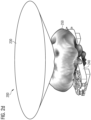
- the radiation pattern 250 for the radar system 200 with the reflector 230 is shown.
- the radiation pattern 250 is a spherical segment centered above the phase center and cut off by the surface of the reflector 230, i.e., the radiation pattern 250 forms a ring which circulates the phase center and is opened upwards.
- the field strength is highest in a horizontal plane through the tip of the reflector 230 and decreases with increasing distance to said horizontal plane. Since the reflector 230 has a rotationally symmetrical shape, the radiation power of the radar beam is distributed (nearly) uniformly over an angular range of 360° along the horizontal plane viewed from the phase center.
- a direction of the reflected radar signal and, consequently, a position and shape of the target region may be mainly dependent on a shape and position of the reflector 230.
- the shape and position of the reflector 230 may be modified to obtain an intended radiation pattern.
- the tilt angle between a trajectory outgoing from the reflector 230 and a trajectory of the initial radar beam is approximately 90°, resulting in a target region mainly extending along a horizontal plane around the radar sensor 210.
- the preferred tilt angle may differ from 90°.
- the opening angle of the tapering is bigger, which causes the reflected radar signal 325 to be tilted towards a plane along the emitting surface (more downwards).
- the tapering is more pointed than that of Fig. 3a , i.e., the opening angle of the tapering is smaller, which causes the reflected radar signal 325 to be tilted away from the plane along the emitting surface (more upwards).
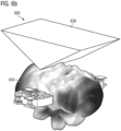
- Fig. 6a and Fig. 6b illustrate an oblique top view of an example of a radar system 600.
- the radar system 600 comprises a radar sensor 610 comprising an antenna configured to emit a radar beam towards a predefined region.
- the radar system 600 comprises a reflector 630 configured to redirect at least part of the radar beam towards a target region different from the predefined region.
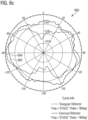
- the first directive gain 662 shows an approximately uniform distribution of the radiation power over the entire angular range whereas the second directive gain 664 exhibits two opposing lobes with an angular range from approximately -30° to -150° and from +30° to +150°, respectively, thus, an angular range from -30° to +30° and from + 150 to -150° (clockwise) is excluded from detection.
- Fig. 7 illustrates an electronic device 700 comprising a radar system 710 and control circuitry 720 configured to control an operation of the electronic device 700 based on an output signal of the radar system 710.
- the radar system 710 comprises a radar sensor and a reflector as described above, e.g., with reference to Fig. 1a and Fig. 1b .
- the radar sensor is configured to emit a radar beam to a predefined region.
- the reflector is configured to redirect at least part of the radar beam towards a target region.
- the control circuitry 720 may be a single dedicated processor, a single shared processor, or a plurality of individual processors, some of which or all of which may be shared, a digital signal processor (DSP) hardware, an application specific integrated circuit (ASIC) or a field programmable gate array (FPGA).
- DSP digital signal processor
- ASIC application specific integrated circuit
- FPGA field programmable gate array
- the control circuitry 720 may optionally be coupled to, e.g., read only memory (ROM) for storing software, random access memory (RAM) and/or non-volatile memory.
- ROM read only memory
- RAM random access memory
- non-volatile memory e.g., compact flash memory
- the radar system 710 may be configured to determine the at least one of presence, the movement, and the distance of the object in an immediate surrounding of the electronic device 700, e.g., in a distance of up to a few meters (e.g., 4 or 5 meters) to the electronic device 700.
- the radar system 710 may be configured to detect presence of a user of the electronic device 700. For instance, the radar system 710 may be configured to determine whether a person is present in a certain area around the electronic device 700 and, optionally, determine whether that person approaches the electronic device 700 or moves away from the electronic device 700.
- the control circuitry 720 may control the operation of the electronic device 700, e.g., by activating or deactivating a certain function of the electronic device 700 based on the output signal, e.g., a certain function may be activated if it is determined that a user of the electronic device 700 is present. For instance, the control circuitry 720 may, if it is determined that a user is close, skip key word activation or automatically play music, activate air-conditioning, heating or alike. The control circuitry 720 may monitor a distance to a user based on the output signal (follow-me function).
- the electronic device 700 may have a (wireless) connection to other electronic devices in its surrounding and communicate the distance to the other electronic devices in order to determine which of the electronic devices is closest to the user, e.g., for connecting a microphone of the determined electronic device with a mobile phone of the user for phone calls.
- the electronic device 700 may be a speaker and be connected to other speakers in its surrounding to enable a dynamic handover of an audio output to one of the speakers closest to the user.
- the electronic device 700 may have a fixed orientation, e.g., a certain surface area of the electronic device 700 may be designed for an orientation to a certain direction, e.g., vertically upwards or downwards, or horizontally to a certain side.
- the orientation may be dependent on a surrounding where the electronic device 700 is operated, e.g., the electronic device 700 may be designed for an orientation away from an obstacle such as a wall or towards an area of interest inside a room.
- the radar system 710 may be integrated into a certain side of the electronic device 700, thus, the fixed orientation of the electronic device 700 may imply a similarly fixed orientation of the radar sensor.
- the integration of the radar system 710 may be selected according to design considerations which may be opposed to the radar function, i.e., the orientation of the radar sensor may, per se, be impractical for the radar application.
- the radar system 710 may be integrated into a top side of the electronic device 700 resulting in an upward orientation of the radar sensor even though objects lateral to the electronic device 700 shall be detected.
- the radar function may require a target region differing from a field of view of the radar sensor, e.g., with an angular range of more than 120°.
- the radar system 710 may overcome a limitation of a conventional radar system by providing the possibility to freely define the target region for matching the requirements of the radar function.
- the radar system 710 may be configured to detect presence of a user in a proximity to the electronic device 700.
- the radar system 710 may be integrated into a top side of the electronic device 700, i.e., facing upwards.
- the reflector of the radar system 710 may provide a coverage of 360° around the electronic device 700, i.e., it may be capable of detecting a user lateral to the electronic device 700 in any direction.
- a position of the electronic device 700 may be intended to be mostly fixed and a limited target region in front of the electronic device 700 may be relevant for monitoring presence of a user.
- the electronic device 700 may be expected to be placed centered inside a room or, potentially, be moved with respect to its position and orientation.
- the radar system 710 may provide a suitable method for detection of an object in an area of interest without the use of multiple sensors, reducing costs and power consumption of the electronic device 700.
- the radar system 710 may also prevent unwanted detection of objects by excluding certain regions around the electronic device 700 from detection. For instance, the radar system 710 may suppress an unwanted detection of movements of, e.g., a fan on the ceiling or a cleaning robot and pet on the floor, without extensive data processing effort or efficiency loss.
- the radar system 710 may allow immunity to detection of objects in an original field of view of the radar sensor. Besides, the radar system 710 may increase a sensitivity of the radar sensor for a desired target region different from a field of view of the radar sensor.
Landscapes
- Engineering & Computer Science (AREA)
- Remote Sensing (AREA)
- Radar, Positioning & Navigation (AREA)
- Physics & Mathematics (AREA)
- Computer Networks & Wireless Communication (AREA)
- General Physics & Mathematics (AREA)
- Electromagnetism (AREA)
- Aerials With Secondary Devices (AREA)
- Radar Systems Or Details Thereof (AREA)
Claims (11)
- Radarsystem (100), umfassend:einen Radarsensor (110), der eine Antenne umfasst, die dazu ausgelegt ist, einen Radarstrahl (120) in Richtung eines vordefinierten Gebiets zu emittieren; undeinen Reflektor (130), der von dem Radarsystem (110) beabstandet und bezüglich einer Symmetrielinie oder einer Symmetrieebene symmetrisch ist, wobei die Symmetrielinie oder die Symmetrieebene parallel zu einer Strahlachse des Radarstrahls (120) ist, wobei der Reflektor (130) ausgelegt ist zum:Umlenken zumindest eines Teils des Radarstrahls (120) in Richtung eines Zielgebiets, das sich von dem vordefinierten Gebiet unterscheidet; undUmlenken einer Reflexion des Radarstrahls (120), die vom Zielgebiet stammt, auf den Radarsensor (110);wobei das Radarsystem (100) dadurch gekennzeichnet ist, dass die Symmetrielinie oder die Symmetrieebene bezüglich eines Phasenzentrums der Antenne versetzt ist.
- Radarsystem (100) nach Anspruch 1, wobei der Radarsensor (110) ein monostatischer Radarsensor ist, und wobei der Reflektor (130) die Reflexion des Radarstrahls (120) auf die Antenne umlenkt.
- Radarsystem (100) nach Anspruch 1 oder 2, wobei sich der Reflektor (130) in Richtung des Radarsensors (110) verjüngt.
- Radarsystem (100) nach einem der vorstehenden Ansprüche, wobei sich der Reflektor (130) in Richtung einer Spitze oder einer Kante, die in Richtung des Radarsensors (110) orientiert ist, verjüngt.
- Radarsystem (100) nach einem der vorstehenden Ansprüche, wobei der Reflektor (130) eine Außenfläche umfasst, die dazu ausgelegt ist, den zumindest Teil des Radarstrahls (120) und die Reflexion des Radarstrahls (120) umzulenken, und
wobei zumindest die Außenfläche des Reflektors (130) metallisch ist. - Radarsystem (100) nach einem der vorstehenden Ansprüche, wobei sich der Reflektor (130) räumlich über eine gesamte Strahlbreite des Radarstrahls (120) erstreckt.
- Radarsystem (100) nach einem der vorstehenden Ansprüche, wobei eine imaginäre Linie zwischen einem Phasenzentrum der Antenne und einem beliebigen Grenzpunkt des vordefinierten Gebiets um mindestens 10 Grad bezüglich einer imaginären Linie zwischen dem Phasenzentrum und einem beliebigen Grenzpunkt des Zielgebiets geneigt ist.
- Radarsystem (100) nach einem der vorstehenden Ansprüche, wobei die Antenne eine emittierende Oberfläche umfasst, die dazu ausgelegt ist, den Radarstrahl (120) zu emittieren, und
wobei sich das Zielgebiet über mindestens 120 Grad entlang einer Ebene parallel zu der emittierenden Oberfläche erstreckt, wenn von einem Phasenzentrum der Antenne aus gesehen. - Radarsystem (100) nach einem der vorstehenden Ansprüche, wobei der Radarsensor (110) dazu ausgelegt ist, basierend auf der Reflexion des Radarstrahls (120) mindestens eines von einem Vorhandensein, einer Bewegung und einer Entfernung eines Objekts in einer Umgebung des Radarsystems (100) zu bestimmen.
- Elektronische Vorrichtung (700), umfassend:ein Radarsystem (710) nach einem der Ansprüche 1 bis 9; undeine Steuerschaltungsanordnung (720), die dazu ausgelegt ist, einen Betrieb der elektronischen Vorrichtung (700) basierend auf einem Ausgangssignal des Radarsystems (710) zu steuern.
- Verfahren (800) zum Betreiben eines Radarsystems nach Anspruch 1,
wobei das Verfahren (800) umfasst:Emittieren (810), an der Antenne des Radarsensors, eines Radarstrahls in Richtung eines vordefinierten Gebiets,wobei die Symmetrielinie oder die Symmetrieebene parallel zu einer Strahlachse des Radarstrahls ist;Umlenken (820), unter Verwendung des Reflektors, des Radarstrahls in Richtung eines Zielgebiets, das sich von dem vordefinierten Gebiet unterscheidet; undUmlenken (830), unter Verwendung des Reflektors, einer Reflexion des Radarstrahls, die von dem Zielgebiet stammt, auf den Radarsensor.
Priority Applications (6)
| Application Number | Priority Date | Filing Date | Title |
|---|---|---|---|
| EP22158073.1A EP4231042B1 (de) | 2022-02-22 | 2022-02-22 | Radarsystem, vorrichtung mit einem radarsystem und verfahren zum betrieb eines radarsystems |
| EP23152765.6A EP4231043A3 (de) | 2022-02-22 | 2023-01-20 | Radarsystem, vorrichtung mit einem radarsystem und verfahren zum betreiben eines radarsystems |
| US18/162,309 US20230266454A1 (en) | 2022-02-22 | 2023-01-31 | Radar system, device comprising a radar system and method for operating a radar system |
| US18/169,465 US20230266437A1 (en) | 2022-02-22 | 2023-02-15 | Radar System, Device Comprising a Radar System and Method for Operating a Radar System |
| CN202310144741.6A CN116643261A (zh) | 2022-02-22 | 2023-02-21 | 雷达系统、包括雷达系统的设备和操作雷达系统的方法 |
| CN202310142369.5A CN116643260A (zh) | 2022-02-22 | 2023-02-21 | 雷达系统、包括雷达系统的设备和操作雷达系统的方法 |
Applications Claiming Priority (1)
| Application Number | Priority Date | Filing Date | Title |
|---|---|---|---|
| EP22158073.1A EP4231042B1 (de) | 2022-02-22 | 2022-02-22 | Radarsystem, vorrichtung mit einem radarsystem und verfahren zum betrieb eines radarsystems |
Publications (2)
| Publication Number | Publication Date |
|---|---|
| EP4231042A1 EP4231042A1 (de) | 2023-08-23 |
| EP4231042B1 true EP4231042B1 (de) | 2025-07-09 |
Family
ID=80447187
Family Applications (2)
| Application Number | Title | Priority Date | Filing Date |
|---|---|---|---|
| EP22158073.1A Active EP4231042B1 (de) | 2022-02-22 | 2022-02-22 | Radarsystem, vorrichtung mit einem radarsystem und verfahren zum betrieb eines radarsystems |
| EP23152765.6A Pending EP4231043A3 (de) | 2022-02-22 | 2023-01-20 | Radarsystem, vorrichtung mit einem radarsystem und verfahren zum betreiben eines radarsystems |
Family Applications After (1)
| Application Number | Title | Priority Date | Filing Date |
|---|---|---|---|
| EP23152765.6A Pending EP4231043A3 (de) | 2022-02-22 | 2023-01-20 | Radarsystem, vorrichtung mit einem radarsystem und verfahren zum betreiben eines radarsystems |
Country Status (3)
| Country | Link |
|---|---|
| US (2) | US20230266454A1 (de) |
| EP (2) | EP4231042B1 (de) |
| CN (2) | CN116643261A (de) |
Families Citing this family (1)
| Publication number | Priority date | Publication date | Assignee | Title |
|---|---|---|---|---|
| GB202319726D0 (en) * | 2023-12-21 | 2024-02-07 | Oxford Rf Solutions Ltd | Multi-directional transducer system |
Family Cites Families (9)
| Publication number | Priority date | Publication date | Assignee | Title |
|---|---|---|---|---|
| CH557544A (de) * | 1972-10-17 | 1974-12-31 | Siemens Ag Albis | Radareinrichtung zum feststellen einer bewegung eines objektes in einem zu ueberwachenden bereich. |
| GB2331185B (en) * | 1983-03-05 | 1999-09-22 | Emi Ltd | Antenna arrangement |
| CN202395161U (zh) * | 2011-12-26 | 2012-08-22 | 上海磁浮交通发展有限公司 | 一种二段结构高功率波束赋形车载天线 |
| US20160306034A1 (en) * | 2014-12-23 | 2016-10-20 | Infineon Technologies Ag | RF System with an RFIC and Antenna System |
| KR20180121372A (ko) * | 2017-04-28 | 2018-11-07 | 엘에스엠트론 주식회사 | 차량용 안테나 장치 |
| DE102017218823A1 (de) * | 2017-10-20 | 2019-04-25 | Fraunhofer-Gesellschaft zur Förderung der angewandten Forschung e.V. | Antennenanordnung zum Abtasten eines Raumes mittels sichtbarer oder unsichtbarer Strahlung |
| JP6590264B2 (ja) * | 2017-11-27 | 2019-10-16 | パナソニックIpマネジメント株式会社 | アンテナ装置 |
| CN113519089A (zh) * | 2019-03-18 | 2021-10-19 | 株式会社自动网络技术研究所 | 移动体用天线装置及通信装置 |
| GB202102538D0 (en) * | 2021-02-23 | 2021-04-07 | Oxford Rf Solutions Ltd | Multi-directional transducer system and method |
-
2022
- 2022-02-22 EP EP22158073.1A patent/EP4231042B1/de active Active
-
2023
- 2023-01-20 EP EP23152765.6A patent/EP4231043A3/de active Pending
- 2023-01-31 US US18/162,309 patent/US20230266454A1/en active Pending
- 2023-02-15 US US18/169,465 patent/US20230266437A1/en not_active Abandoned
- 2023-02-21 CN CN202310144741.6A patent/CN116643261A/zh active Pending
- 2023-02-21 CN CN202310142369.5A patent/CN116643260A/zh active Pending
Also Published As
| Publication number | Publication date |
|---|---|
| US20230266437A1 (en) | 2023-08-24 |
| CN116643260A (zh) | 2023-08-25 |
| EP4231042A1 (de) | 2023-08-23 |
| CN116643261A (zh) | 2023-08-25 |
| EP4231043A3 (de) | 2023-10-25 |
| US20230266454A1 (en) | 2023-08-24 |
| EP4231043A2 (de) | 2023-08-23 |
Similar Documents
| Publication | Publication Date | Title |
|---|---|---|
| US8854257B2 (en) | Conformal array, luneburg lens antenna system | |
| JP7271507B2 (ja) | 一次元での受信アンテナの分散配置によって二次元での物体の角度を判断するための受信アレイを有するイメージングレーダシステム | |
| US12487324B2 (en) | Systems and methods for providing wide beam radar arrays | |
| US12021304B2 (en) | Multi-beam antenna module | |
| JP2018061112A (ja) | アンテナ、センサ及び車載システム | |
| JP2022543045A (ja) | 屈折率分布型レンズに基づく通信システム | |
| EP4231042B1 (de) | Radarsystem, vorrichtung mit einem radarsystem und verfahren zum betrieb eines radarsystems | |
| US7453411B2 (en) | Antenna device and radar apparatus including the same | |
| US20210313701A1 (en) | Antenna for transmitting and/or receiving an electromagnetic wave, and system comprising this antenna | |
| CN102820528B (zh) | 一种雷达天线以及雷达系统 | |
| CN102820526B (zh) | 一种雷达天线以及雷达系统 | |
| KR102147952B1 (ko) | 패턴이 형성된 혼 안테나 및 이를 구비한 안테나 장치 | |
| US4631547A (en) | Reflector antenna having sidelobe suppression elements | |
| US8618999B2 (en) | Microwave motion sensor with a reflector | |
| CN102820529B (zh) | 一种雷达天线以及雷达系统 | |
| CN102820527A (zh) | 一种雷达天线以及雷达系统 | |
| GB2044006A (en) | Radar antenna | |
| RU2713034C1 (ru) | Многослойная диэлектрическая тороидальная антенна | |
| WO2020183016A1 (en) | Antenna for 2d electronical beam-steering using multiple pre-shaped beams | |
| KR100983406B1 (ko) | 안테나 장치 | |
| TWI828161B (zh) | 多波束天線模組 | |
| US20260029526A1 (en) | Microwave imaging radar sensor | |
| Younis et al. | A parallel-Plate luneburg lens sensor concept for automatic cruise control applications | |
| JPH04113286A (ja) | レンズアンテナ |
Legal Events
| Date | Code | Title | Description |
|---|---|---|---|
| PUAI | Public reference made under article 153(3) epc to a published international application that has entered the european phase |
Free format text: ORIGINAL CODE: 0009012 |
|
| STAA | Information on the status of an ep patent application or granted ep patent |
Free format text: STATUS: EXAMINATION IS IN PROGRESS |
|
| 17P | Request for examination filed |
Effective date: 20221221 |
|
| AK | Designated contracting states |
Kind code of ref document: A1 Designated state(s): AL AT BE BG CH CY CZ DE DK EE ES FI FR GB GR HR HU IE IS IT LI LT LU LV MC MK MT NL NO PL PT RO RS SE SI SK SM TR |
|
| REG | Reference to a national code |
Ref country code: DE Ref legal event code: R079 Free format text: PREVIOUS MAIN CLASS: G01S0007020000 Ipc: G01S0007030000 Ref document number: 602022017152 Country of ref document: DE |
|
| GRAP | Despatch of communication of intention to grant a patent |
Free format text: ORIGINAL CODE: EPIDOSNIGR1 |
|
| STAA | Information on the status of an ep patent application or granted ep patent |
Free format text: STATUS: GRANT OF PATENT IS INTENDED |
|
| RIC1 | Information provided on ipc code assigned before grant |
Ipc: G01S 13/56 20060101ALN20250122BHEP Ipc: G01S 13/04 20060101ALN20250122BHEP Ipc: H01Q 15/14 20060101ALI20250122BHEP Ipc: H01Q 15/18 20060101ALI20250122BHEP Ipc: H01Q 15/16 20060101ALI20250122BHEP Ipc: H01Q 19/10 20060101ALI20250122BHEP Ipc: G01S 7/02 20060101ALI20250122BHEP Ipc: G01S 13/00 20060101ALI20250122BHEP Ipc: G01S 7/03 20060101AFI20250122BHEP |
|
| INTG | Intention to grant announced |
Effective date: 20250207 |
|
| GRAS | Grant fee paid |
Free format text: ORIGINAL CODE: EPIDOSNIGR3 |
|
| P01 | Opt-out of the competence of the unified patent court (upc) registered |
Free format text: CASE NUMBER: APP_20517/2025 Effective date: 20250429 |
|
| GRAA | (expected) grant |
Free format text: ORIGINAL CODE: 0009210 |
|
| STAA | Information on the status of an ep patent application or granted ep patent |
Free format text: STATUS: THE PATENT HAS BEEN GRANTED |
|
| AK | Designated contracting states |
Kind code of ref document: B1 Designated state(s): AL AT BE BG CH CY CZ DE DK EE ES FI FR GB GR HR HU IE IS IT LI LT LU LV MC MK MT NL NO PL PT RO RS SE SI SK SM TR |
|
| REG | Reference to a national code |
Ref country code: GB Ref legal event code: FG4D |
|
| REG | Reference to a national code |
Ref country code: CH Ref legal event code: EP |
|
| REG | Reference to a national code |
Ref country code: IE Ref legal event code: FG4D |
|
| REG | Reference to a national code |
Ref country code: DE Ref legal event code: R096 Ref document number: 602022017152 Country of ref document: DE |
|
| REG | Reference to a national code |
Ref country code: NL Ref legal event code: MP Effective date: 20250709 |
|
| PG25 | Lapsed in a contracting state [announced via postgrant information from national office to epo] |
Ref country code: PT Free format text: LAPSE BECAUSE OF FAILURE TO SUBMIT A TRANSLATION OF THE DESCRIPTION OR TO PAY THE FEE WITHIN THE PRESCRIBED TIME-LIMIT Effective date: 20251110 |
|
| PG25 | Lapsed in a contracting state [announced via postgrant information from national office to epo] |
Ref country code: NL Free format text: LAPSE BECAUSE OF FAILURE TO SUBMIT A TRANSLATION OF THE DESCRIPTION OR TO PAY THE FEE WITHIN THE PRESCRIBED TIME-LIMIT Effective date: 20250709 |
|
| REG | Reference to a national code |
Ref country code: AT Ref legal event code: MK05 Ref document number: 1812294 Country of ref document: AT Kind code of ref document: T Effective date: 20250709 |
|
| PG25 | Lapsed in a contracting state [announced via postgrant information from national office to epo] |
Ref country code: IS Free format text: LAPSE BECAUSE OF FAILURE TO SUBMIT A TRANSLATION OF THE DESCRIPTION OR TO PAY THE FEE WITHIN THE PRESCRIBED TIME-LIMIT Effective date: 20251109 |
|
| PG25 | Lapsed in a contracting state [announced via postgrant information from national office to epo] |
Ref country code: NO Free format text: LAPSE BECAUSE OF FAILURE TO SUBMIT A TRANSLATION OF THE DESCRIPTION OR TO PAY THE FEE WITHIN THE PRESCRIBED TIME-LIMIT Effective date: 20251009 |
|
| REG | Reference to a national code |
Ref country code: LT Ref legal event code: MG9D |
|
| PG25 | Lapsed in a contracting state [announced via postgrant information from national office to epo] |
Ref country code: AT Free format text: LAPSE BECAUSE OF FAILURE TO SUBMIT A TRANSLATION OF THE DESCRIPTION OR TO PAY THE FEE WITHIN THE PRESCRIBED TIME-LIMIT Effective date: 20250709 |
|
| PG25 | Lapsed in a contracting state [announced via postgrant information from national office to epo] |
Ref country code: FI Free format text: LAPSE BECAUSE OF FAILURE TO SUBMIT A TRANSLATION OF THE DESCRIPTION OR TO PAY THE FEE WITHIN THE PRESCRIBED TIME-LIMIT Effective date: 20250709 |
|
| PG25 | Lapsed in a contracting state [announced via postgrant information from national office to epo] |
Ref country code: HR Free format text: LAPSE BECAUSE OF FAILURE TO SUBMIT A TRANSLATION OF THE DESCRIPTION OR TO PAY THE FEE WITHIN THE PRESCRIBED TIME-LIMIT Effective date: 20250709 |
|
| PG25 | Lapsed in a contracting state [announced via postgrant information from national office to epo] |
Ref country code: GR Free format text: LAPSE BECAUSE OF FAILURE TO SUBMIT A TRANSLATION OF THE DESCRIPTION OR TO PAY THE FEE WITHIN THE PRESCRIBED TIME-LIMIT Effective date: 20251010 |
|
| PG25 | Lapsed in a contracting state [announced via postgrant information from national office to epo] |
Ref country code: SE Free format text: LAPSE BECAUSE OF FAILURE TO SUBMIT A TRANSLATION OF THE DESCRIPTION OR TO PAY THE FEE WITHIN THE PRESCRIBED TIME-LIMIT Effective date: 20250709 |
|
| PG25 | Lapsed in a contracting state [announced via postgrant information from national office to epo] |
Ref country code: LV Free format text: LAPSE BECAUSE OF FAILURE TO SUBMIT A TRANSLATION OF THE DESCRIPTION OR TO PAY THE FEE WITHIN THE PRESCRIBED TIME-LIMIT Effective date: 20250709 |
|
| PG25 | Lapsed in a contracting state [announced via postgrant information from national office to epo] |
Ref country code: PL Free format text: LAPSE BECAUSE OF FAILURE TO SUBMIT A TRANSLATION OF THE DESCRIPTION OR TO PAY THE FEE WITHIN THE PRESCRIBED TIME-LIMIT Effective date: 20250709 Ref country code: BG Free format text: LAPSE BECAUSE OF FAILURE TO SUBMIT A TRANSLATION OF THE DESCRIPTION OR TO PAY THE FEE WITHIN THE PRESCRIBED TIME-LIMIT Effective date: 20250709 |
|
| PG25 | Lapsed in a contracting state [announced via postgrant information from national office to epo] |
Ref country code: RS Free format text: LAPSE BECAUSE OF FAILURE TO SUBMIT A TRANSLATION OF THE DESCRIPTION OR TO PAY THE FEE WITHIN THE PRESCRIBED TIME-LIMIT Effective date: 20251009 |
|
| PG25 | Lapsed in a contracting state [announced via postgrant information from national office to epo] |
Ref country code: ES Free format text: LAPSE BECAUSE OF FAILURE TO SUBMIT A TRANSLATION OF THE DESCRIPTION OR TO PAY THE FEE WITHIN THE PRESCRIBED TIME-LIMIT Effective date: 20250709 |
|
| PG25 | Lapsed in a contracting state [announced via postgrant information from national office to epo] |
Ref country code: SM Free format text: LAPSE BECAUSE OF FAILURE TO SUBMIT A TRANSLATION OF THE DESCRIPTION OR TO PAY THE FEE WITHIN THE PRESCRIBED TIME-LIMIT Effective date: 20250709 |
|
| PGFP | Annual fee paid to national office [announced via postgrant information from national office to epo] |
Ref country code: GB Payment date: 20260220 Year of fee payment: 5 |
|
| PG25 | Lapsed in a contracting state [announced via postgrant information from national office to epo] |
Ref country code: DK Free format text: LAPSE BECAUSE OF FAILURE TO SUBMIT A TRANSLATION OF THE DESCRIPTION OR TO PAY THE FEE WITHIN THE PRESCRIBED TIME-LIMIT Effective date: 20250709 |
|
| PG25 | Lapsed in a contracting state [announced via postgrant information from national office to epo] |
Ref country code: IT Free format text: LAPSE BECAUSE OF FAILURE TO SUBMIT A TRANSLATION OF THE DESCRIPTION OR TO PAY THE FEE WITHIN THE PRESCRIBED TIME-LIMIT Effective date: 20250709 |