EP4231079A1 - Système d'objectif, unité de capture d'image et dispositif électronique - Google Patents
Système d'objectif, unité de capture d'image et dispositif électronique Download PDFInfo
- Publication number
- EP4231079A1 EP4231079A1 EP22174468.3A EP22174468A EP4231079A1 EP 4231079 A1 EP4231079 A1 EP 4231079A1 EP 22174468 A EP22174468 A EP 22174468A EP 4231079 A1 EP4231079 A1 EP 4231079A1
- Authority
- EP
- European Patent Office
- Prior art keywords
- lens
- lens group
- image
- group
- counted
- Prior art date
- Legal status (The legal status is an assumption and is not a legal conclusion. Google has not performed a legal analysis and makes no representation as to the accuracy of the status listed.)
- Pending
Links
Images







Classifications
-
- G—PHYSICS
- G02—OPTICS
- G02B—OPTICAL ELEMENTS, SYSTEMS OR APPARATUS
- G02B13/00—Optical objectives specially designed for the purposes specified below
- G02B13/001—Miniaturised objectives for electronic devices, e.g. portable telephones, webcams, PDAs, small digital cameras
- G02B13/0015—Miniaturised objectives for electronic devices, e.g. portable telephones, webcams, PDAs, small digital cameras characterised by the lens design
- G02B13/002—Miniaturised objectives for electronic devices, e.g. portable telephones, webcams, PDAs, small digital cameras characterised by the lens design having at least one aspherical surface
- G02B13/004—Miniaturised objectives for electronic devices, e.g. portable telephones, webcams, PDAs, small digital cameras characterised by the lens design having at least one aspherical surface having four lenses
-
- G—PHYSICS
- G02—OPTICS
- G02B—OPTICAL ELEMENTS, SYSTEMS OR APPARATUS
- G02B7/00—Mountings, adjusting means, or light-tight connections, for optical elements
- G02B7/02—Mountings, adjusting means, or light-tight connections, for optical elements for lenses
- G02B7/021—Mountings, adjusting means, or light-tight connections, for optical elements for lenses for more than one lens
-
- G—PHYSICS
- G02—OPTICS
- G02B—OPTICAL ELEMENTS, SYSTEMS OR APPARATUS
- G02B13/00—Optical objectives specially designed for the purposes specified below
- G02B13/001—Miniaturised objectives for electronic devices, e.g. portable telephones, webcams, PDAs, small digital cameras
- G02B13/0015—Miniaturised objectives for electronic devices, e.g. portable telephones, webcams, PDAs, small digital cameras characterised by the lens design
- G02B13/002—Miniaturised objectives for electronic devices, e.g. portable telephones, webcams, PDAs, small digital cameras characterised by the lens design having at least one aspherical surface
- G02B13/0045—Miniaturised objectives for electronic devices, e.g. portable telephones, webcams, PDAs, small digital cameras characterised by the lens design having at least one aspherical surface having five or more lenses
-
- G—PHYSICS
- G02—OPTICS
- G02B—OPTICAL ELEMENTS, SYSTEMS OR APPARATUS
- G02B13/00—Optical objectives specially designed for the purposes specified below
- G02B13/001—Miniaturised objectives for electronic devices, e.g. portable telephones, webcams, PDAs, small digital cameras
- G02B13/0015—Miniaturised objectives for electronic devices, e.g. portable telephones, webcams, PDAs, small digital cameras characterised by the lens design
- G02B13/002—Miniaturised objectives for electronic devices, e.g. portable telephones, webcams, PDAs, small digital cameras characterised by the lens design having at least one aspherical surface
- G02B13/003—Miniaturised objectives for electronic devices, e.g. portable telephones, webcams, PDAs, small digital cameras characterised by the lens design having at least one aspherical surface having two lenses
-
- G—PHYSICS
- G02—OPTICS
- G02B—OPTICAL ELEMENTS, SYSTEMS OR APPARATUS
- G02B13/00—Optical objectives specially designed for the purposes specified below
- G02B13/001—Miniaturised objectives for electronic devices, e.g. portable telephones, webcams, PDAs, small digital cameras
- G02B13/0055—Miniaturised objectives for electronic devices, e.g. portable telephones, webcams, PDAs, small digital cameras employing a special optical element
- G02B13/0065—Miniaturised objectives for electronic devices, e.g. portable telephones, webcams, PDAs, small digital cameras employing a special optical element having a beam-folding prism or mirror
-
- G—PHYSICS
- G02—OPTICS
- G02B—OPTICAL ELEMENTS, SYSTEMS OR APPARATUS
- G02B13/00—Optical objectives specially designed for the purposes specified below
- G02B13/001—Miniaturised objectives for electronic devices, e.g. portable telephones, webcams, PDAs, small digital cameras
- G02B13/009—Miniaturised objectives for electronic devices, e.g. portable telephones, webcams, PDAs, small digital cameras having zoom function
-
- G—PHYSICS
- G02—OPTICS
- G02B—OPTICAL ELEMENTS, SYSTEMS OR APPARATUS
- G02B13/00—Optical objectives specially designed for the purposes specified below
- G02B13/18—Optical objectives specially designed for the purposes specified below with lenses having one or more non-spherical faces, e.g. for reducing geometrical aberration
-
- G—PHYSICS
- G02—OPTICS
- G02B—OPTICAL ELEMENTS, SYSTEMS OR APPARATUS
- G02B9/00—Optical objectives characterised both by the number of the components and their arrangements according to their sign, i.e. + or -
- G02B9/04—Optical objectives characterised both by the number of the components and their arrangements according to their sign, i.e. + or - having two components only
Definitions
- the present disclosure relates to a photographing lens system, an image capturing unit and an electronic device, more particularly to a photographing lens system and an image capturing unit applicable to an electronic device.
- a photographing lens system includes, in order from an object side to an image side along an optical path, a front lens group and a rear lens group.
- the front lens group includes four lens elements
- the rear lens group includes four lens elements.
- Each of the four lens elements of the front lens group and the four lens elements of the rear lens group has an object-side surface facing toward the object side and an image-side surface facing toward the image side.
- a second lens element counted from the image side in the front lens group has negative refractive power.
- the image-side surface of a first lens element counted from the image side in the front lens group is convex in a paraxial region thereof.
- a second lens element counted from the object side in the rear lens group has negative refractive power.
- the object-side surface of a first lens element counted from the image side in the rear lens group is concave in a paraxial region thereof. At least one of the object-side surface and the image-side surface of at least one lens element in the rear lens group is aspheric.
- an Abbe number of the first lens element counted from the image side in the rear lens group is Vrr1
- an Abbe number of a second lens element counted from the image side in the rear lens group is Vrr2
- an axial distance between the image-side surface of the first lens element counted from the image side in the front lens group and the object-side surface of a first lens element counted from the object side in the rear lens group is TGfGr
- a central thickness of the first lens element counted from the image side in the front lens group is Tfrl
- a photographing lens system includes, in order from an object side to an image side along an optical path, a front lens group and a rear lens group.
- the front lens group includes one lens element
- the rear lens group includes four lens elements.
- Each of the one lens element of the front lens group and the four lens elements of the rear lens group has an object-side surface facing toward the object side and an image-side surface facing toward the image side.
- the object-side surface of a first lens element counted from the object side in the front lens group is convex in a paraxial region thereof.
- a second lens element counted from the object side in the rear lens group has negative refractive power.
- the object-side surface of the second lens element counted from the object side in the rear lens group is concave in a paraxial region thereof.
- the object-side surface of a second lens element counted from the image side in the rear lens group is convex in a paraxial region thereof.
- a first lens element counted from the image side in the rear lens group has negative refractive power.
- At least one of the object-side surface and the image-side surface of at least one lens element in the rear lens group is aspheric.
- an Abbe number of the first lens element counted from the image side in the rear lens group is Vrr1
- an Abbe number of the second lens element counted from the image side in the rear lens group is Vrr2
- an axial distance between the image-side surface of a first lens element counted from the image side in the front lens group and the object-side surface of a first lens element counted from the object side in the rear lens group is TGfGr
- a central thickness of the first lens element counted from the image side in the front lens group is Tfrl
- a photographing lens system includes a first front lens group, a second front lens group, a rear lens group and an optical path switching mechanism.
- the optical path switching mechanism is configured for the photographing lens system to be switched between a first optical path state and a second optical path state.
- the photographing lens system When the photographing lens system is in the first optical path state, the photographing lens system includes, in order from an object side to an image side along a first optical path, the first front lens group and the rear lens group.
- the photographing lens system When the photographing lens system is in the second optical path state, the photographing lens system includes, in order from the object side to the image side along a second optical path, the second front lens group and the rear lens group.
- the first front lens group includes at least three lens elements
- the second front lens group includes at least one lens element
- the rear lens group includes at least two lens elements.
- Each of the at least three lens elements of the first front lens group, the at least one lens element of the second front lens group and the at least two lens elements of the rear lens group has an object-side surface facing toward the object side and an image-side surface facing toward the image side. At least one of the object-side surface and the image-side surface of at least one lens element in the rear lens group is aspheric.
- a focal length of the photographing lens system in the first optical path state is FS1
- a focal length of the photographing lens system in the second optical path state is FS2
- a minimum value among Abbe numbers of all lens elements in the rear lens group is minVGr
- an image capturing unit includes one of the aforementioned photographing lens systems and an image sensor, wherein the image sensor is disposed on an image surface of the photographing lens system.
- an electronic device includes the aforementioned image capturing unit.
- a photographing lens system includes, in order from an object side to an image side along an optical path, a front lens group and a rear lens group.
- the front lens group includes at least one lens element
- the rear lens group includes at least two lens elements. Therefore, such configuration is favorable for improving image quality.
- each of the lens elements of the front lens group and the rear lens group has an object-side surface facing toward the object side and an image-side surface facing toward the image side.
- the photographing lens system can include at least one reflector, and the reflector can be, for example, a prism or a flat mirror having a reflection surface. Therefore, the reflector is configured to fold the optical path, so that the mechanical arrangement can be more flexible. Moreover, the reflector can be disposed in the front lens group. Therefore, it is favorable for adjusting the arrangement of lens elements so as to improve image quality. Moreover, the reflector can be disposed between the front lens group and the rear lens group. Therefore, it is favorable for adjusting the arrangement of lens elements so as to obtain a balance between the size distribution and image quality. Moreover, the reflector can be applied to, for example, systems having switchable optical paths so as to reduce the mechanical size.
- the front lens group includes one lens element. Therefore, it is favorable for balancing the field of view, size and image quality.
- the front lens group can include at least two lens elements. Therefore, it is favorable for improving image quality and forming a long-focus configuration.
- the front lens group can also include at least three lens elements.
- the front lens group can also include at least four lens elements. In some configurations, the front lens group can include four lens elements. Therefore, it is favorable for balancing the field of view, size and image quality.
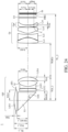
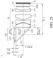
- Fig. 24 and Fig. 25 show schematic views of the photographing lens system respectively in the first optical path state and the second optical path state according to the 1st embodiment of the present disclosure.
- a first lens element counted from the object side in the front lens group is a first front group first lens element Lf11
- a second lens element counted from the object side in the front lens group is a first front group second lens element Lf12
- a second lens element counted from the image side in the front lens group is a first front group third lens element Lf13
- a first lens element counted from the image side in the front lens group is a first front group fourth lens element Lf14.
- a first lens element counted from the object side in the front lens group is a second front group first lens element Lf21
- a first lens element counted from the image side in the front lens group is the second front group first lens element Lf21.
- the first lens element counted from the object side in the front lens group can have positive refractive power. Therefore, it is favorable for reducing the size of the front lens group.
- the object-side surface of the first lens element counted from the object side in the front lens group can be convex in a paraxial region thereof. Therefore, it is favorable for adjusting the traveling direction of light into the photographing lens system so as to reduce the outer diameter of the front lens group.
- the second lens element counted from the image side in the front lens group can have negative refractive power. Therefore, it is favorable for balancing the refractive power of the front lens group so as to correct aberrations.
- the image-side surface of the second lens element counted from the image side in the front lens group can be concave in a paraxial region thereof. Therefore, it is favorable for adjusting the traveling direction of light so as to reduce the outer diameter of the front lens group.
- the first lens element counted from the image side in the front lens group can have positive refractive power. Therefore, it is favorable for collaborating with the rear lens group so as to reduce the outer diameter of the photographing lens system.
- the object-side surface of the first lens element counted from the image side in the front lens group can be concave in a paraxial region thereof. Therefore, it is favorable for collaborating with the other lens elements so as to correct aberrations.
- the image-side surface of the first lens element counted from the image side in the front lens group can be convex in a paraxial region thereof. Therefore, it is favorable for adjusting the traveling direction of light so as to adjust the distance between the front and rear lens groups in a proper range.
- the rear lens group can include at least three lens elements. Therefore, it is favorable for improving image quality and forming a long-focus configuration. Moreover, the rear lens group can also include at least four lens elements. In some configurations, the rear lens group can include four lens elements. Therefore, it is favorable for balancing the field of view, size and image quality.
- At least one of the object-side surface and the image-side surface of at least one lens element in the rear lens group is aspheric. Therefore, it is favorable for increasing the shape variation of the lens element so as to correct aberrations and reduce the size of the lens element.
- a first lens element counted from the object side in the rear lens group is a rear group first lens element Lr1
- a second lens element counted from the object side in the rear lens group is a rear group second lens element Lr2
- a second lens element counted from the image side in the rear lens group is a rear group third lens element Lr3
- a first lens element counted from the image side in the rear lens group is a rear group fourth lens element Lr4.
- the first lens element counted from the object side in the rear lens group can have positive refractive power. Therefore, it is favorable for reducing the size of the rear lens group.
- the object-side surface of the first lens element counted from the object side in the rear lens group can be convex in a paraxial region thereof. Therefore, it is favorable for adjusting the traveling direction of light into the rear lens group so as to reduce the outer diameter of the rear lens group.
- the image-side surface of the first lens element counted from the object side in the rear lens group can be convex in a paraxial region thereof. Therefore, it is favorable for adjusting the surface shape and refractive power of the first lens element counted from the object side in the rear lens group so as to reduce the length of the rear lens group.
- the second lens element counted from the object side in the rear lens group can have negative refractive power. Therefore, it is favorable for collaborating with the first lens element counted from the object side in the rear lens group so as to balance the refractive power distribution and thus correct aberrations, such as spherical aberration.
- the object-side surface of the second lens element counted from the object side in the rear lens group can be concave in a paraxial region thereof. Therefore, it is favorable for collaborating with the first lens element counted from the object side in the rear lens group so as to correct aberrations.
- the second lens element counted from the image side in the rear lens group can have positive refractive power. Therefore, it is favorable for collaborating with the first lens element counted from the image side in the rear lens group so as to correct aberrations.
- the object-side surface of the second lens element counted from the image side in the rear lens group can be convex in a paraxial region thereof. Therefore, it is favorable for adjusting the surface shape and refractive power of the second lens element counted from the image side in the rear lens group so as to reduce the outer diameter of the rear lens group.
- the first lens element counted from the image side in the rear lens group can have negative refractive power. Therefore, it is favorable for adjusting the back focal length in a proper range.
- the object-side surface of the first lens element counted from the image side in the rear lens group can be concave in a paraxial region thereof. Therefore, it is favorable for adjusting the surface shape and refractive power of the first lens element counted from the image side in the rear lens group so as to correct aberrations.
- the object-side surface of the first lens element counted from the image side in the rear lens group can have at least one critical point in an off-axis region thereof. Therefore, it is favorable for correcting off-axis aberrations, such as field curvature.
- the object-side surface of the first lens element counted from the image side in the rear lens group can have at least one critical point in the off-axis region thereof satisfying the following condition: 0.50 ⁇ YCrrlf/Yrrlf ⁇ 0.90. Therefore, it is favorable for correcting aberrations. Please refer to Fig.
- FIG. 24 which shows a schematic view of YCrrlf, Yrrlf and the critical point C in the off-axis region of the object-side surface of the rear group fourth lens element Lr4 according to the 1st embodiment.
- the critical point C in the off-axis region of the object-side surface of the rear group fourth lens element Lr4 in Fig. 24 is only exemplary. In this and other embodiments of the present disclosure, the object-side surface and the image-side surface of each lens element can have one or more non-axial critical points.
- the photographing lens system can include two front lens groups, which are a first front lens group and a second front lens group.
- the first front lens group includes four lens elements
- the second front lens group includes one lens element
- the rear lens group includes four lens elements.
- the photographing lens system can further include an optical path switching mechanism configured for the photographing lens system to be switched between a first optical path state and a second optical path state.
- the photographing lens system includes, in order from the object side to the image side along a first optical path, the first front lens group and the rear lens group.
- the photographing lens system When the photographing lens system is in the second optical path state, the photographing lens system includes, in order from the object side to the image side along a second optical path, the second front lens group and the rear lens group. Therefore, by sharing a rear lens group in both optical path states, the space occupied by the two optical paths can be reduced. According to the present disclosure, a focal length of the photographing lens system in the first optical path state can be larger than a focal length of the photographing lens system in the second optical path state. Please refer to Fig. 1, Fig. 2 , Fig. 5 and Fig. 6 to Fig. 8 . Fig. 1 and Fig.
- FIG 5 show schematic views of the image capturing unit when the photographing lens system is in the first optical path state according to the 1st embodiment of the present disclosure
- Fig. 2 and Fig. 6 to Fig. 8 show schematic views of various examples of the image capturing unit when the photographing lens system is in the second optical path state according to the 1st embodiment of the present disclosure.
- the photographing lens system can include at least two reflectors, and the at least two reflectors can include a first reflector and a second reflector.
- the first reflector can be disposed in the first front lens group.
- the second reflector can be located between the second front lens group and the rear lens group in the second optical path. Therefore, it is favorable for adjusting the arrangement of lens elements so as to improve image quality and obtain a balance between the size distribution and image quality.
- the optical path switching mechanism can include at least one reflector, and the at least one reflector is movable or rotatable relative to the first front lens group, the second front lens group or the rear lens group. Therefore, it is favorable for simplifying the design of the optical path switching mechanism and reducing the space occupied by the photographing lens system.
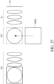
- Fig. 26 and Fig. 27 Fig. 26 is a schematic side view of a configuration of an optical path switching mechanism in a photographing lens system according to one embodiment of the present disclosure
- Fig. 27 is a schematic top view of another configuration of an optical path switching mechanism in a photographing lens system according to one embodiment of the present disclosure.
- the optical path switching mechanism includes a reflector SRM, and the reflector SRM is, for example, a flat mirror.
- the reflector SRM is rotatable relative to the first front lens group Gf1, the second front lens group Gf2, the rear lens group Gr and the image sensor IS.
- the optical path switching mechanism is configured for the photographing lens system to be switched between the first optical path state and the second optical path state by rotating the reflector SRM.
- the reflector SRM of the optical path switching mechanism can be rotated to a position (as shown by the dotted line) located between the second front lens group Gf2 and the rear lens group Gr in the second optical path so as to switch the photographing lens system from the first optical path state to the second optical path state, or the reflector SRM can be rotated away from the position between the second front lens group Gf2 and the rear lens group Gr so as to switch the photographing lens system from the second optical path state to the first optical path state.
- the optical path switching mechanism includes a reflector SRM, and the reflector SRM is movable relative to the first front lens group Gf1, the second front lens group Gf2, the rear lens group Gr and the image sensor IS.
- the optical path switching mechanism is configured for the photographing lens system to be switched between the first optical path state and the second optical path state by moving the reflector SRM.
- the reflector SRM of the optical path switching mechanism can be moved to a position (as shown by the dotted line) located between the second front lens group Gf2 and the rear lens group Gr in the second optical path so as to switch the photographing lens system from the first optical path state to the second optical path state, or the reflector SRM can be moved away from the position between the second front lens group Gf2 and the rear lens group Gr so as to switch the photographing lens system from the second optical path state to the first optical path state.
- Fig. 26 and Fig. 27 show that the optical path switching mechanism switches optical paths by moving or rotating the reflector, but the present disclosure is not limited thereto.
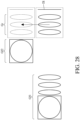
- Fig. 28 and Fig. 29 are schematic top view of another configuration of an optical path switching mechanism in a photographing lens system according to one embodiment of the present disclosure
- Fig. 29 is a schematic top view of another configuration of an optical path switching mechanism in a photographing lens system according to one embodiment of the present disclosure.
- the optical path switching mechanism includes the rear lens group Gr and the image sensor IS, and the rear lens group Gr and the image sensor IS are movable relative to the first front lens group Gf1 and the second front lens group Gf2.
- the optical path switching mechanism is configured for the photographing lens system to be switched between the first optical path state and the second optical path state by moving the rear lens group Gr and the image sensor IS.
- the rear lens group Gr and the image sensor IS of the optical path switching mechanism can be moved from a position (as shown by the solid line) where the rear lens group Gr and the image sensor IS correspond to the first front lens group Gf1 in the first optical path to a position (as shown by the dotted line) where the rear lens group Gr and the image sensor IS correspond to the second front lens group Gf2 in the second optical path so as to switch the photographing lens system from the first optical path state to the second optical path state.
- the optical path switching mechanism includes the first front lens group Gf1 and the second front lens group Gf2, and the first front lens group Gf1 and the second front lens group Gf2 are movable relative to the rear lens group Gr and the image sensor IS.
- the optical path switching mechanism is configured for the photographing lens system to be switched between the first optical path state and the second optical path state by moving the first front lens group Gf1 and the second front lens group Gf2.
- the first front lens group Gf1 and the second front lens group Gf2 of the optical path switching mechanism can be moved from a position (as shown by the solid line) where the first front lens group Gf1 corresponds to the rear lens group Gr to a position (as shown by the dotted line) where the second front lens group Gf2 corresponds to the rear lens group Gr so as to switch the photographing lens system from the first optical path state to the second optical path state.
- the optical path switching mechanism switches optical paths by moving or rotating some components (e.g., lens elements or reflector).
- some components e.g., lens elements or reflector
- the type, number and arrangement of components included in the optical path switching mechanism can be altered according to actual requirements, and the present disclosure is not limited thereto.
- the rear lens group can include a movable lens subgroup, and the movable lens subgroup includes at least one lens element. Therefore, it is favorable for focusing so as to improve image quality.
- the movable lens subgroup can include the first lens element counted from the image side in the rear lens group. Therefore, it is favorable for simplifying the mechanical design.
- the movable lens subgroup can be moved along the optical axis. Therefore, it is favorable for reducing the required number of lens elements for achieving the same zoom ratio so as to reduce the size of the photographing lens system.
- the movable lens subgroup can be moved towards the image side along the optical axis.
- the movable lens subgroup can have negative refractive power. Therefore, it is favorable for reducing the total length of the rear lens group.
- a focal length of the movable lens subgroup is FGm
- a central thickness of the movable lens subgroup is TGm
- the following condition can be satisfied: -50.0 ⁇ FGm/TGm ⁇ -10.0. Therefore, it is favorable for adjusting the arrangement of the movable lens subgroup so as to reduce the size of the movable lens subgroup.
- the following condition can also be satisfied: -40.0 ⁇ FGm/TGm ⁇ -13.0.
- the following condition can also be satisfied: -30.0 ⁇ FGm/TGm ⁇ -16.0. Please refer to Fig.
- Said focal length of the movable lens subgroup is a composite focal length of all lens elements in the movable lens subgroup.
- Said central thickness of the movable lens subgroup is an axial distance between the object-side surface of the first lens element counted from the object side in the movable lens subgroup and the image-side surface of the first lens element counted from the image side in the movable lens subgroup.
- said focal length of the movable lens subgroup is the focal length of the one lens element
- said central thickness of the movable lens subgroup is the central thickness of the one lens element.
- the following condition can also be satisfied: 2.4 ⁇ TGfGr/Tfrl. Moreover, the following condition can also be satisfied: 3.2 ⁇ TGfGr/Tfrl. Moreover, the following condition can also be satisfied: 4.0 ⁇ TGfGr/Tfrl. Moreover, the following condition can also be satisfied: TGfGr/Tfrl ⁇ 50. Therefore, it is favorable for adjusting the arrangement of the lens groups so as to reduce the space occupied by the lens groups. Moreover, the following condition can also be satisfied: TGfGr/Tfrl ⁇ 35. Moreover, the following condition can also be satisfied: TGfGr/Tfrl ⁇ 25.
- Fig. 24 shows a schematic view of TGfGr and Tfr1 according to the 1st embodiment
- Fig. 25 shows a schematic view of TGfGr_1, TGfGr_2 and Tfr1 according to the 1st embodiment. As shown in Fig.
- an axial distance between the image-side surface of the first lens element counted from the image side in the second front lens group Gf2 (i.e., the image-side surface of the second front group first lens element Lf21) and the reflection surface E2S of the reflection mirror E2 (i.e., the reflector) is TGfGr_1
- an axial distance between the reflection surface E2S of the reflection mirror E2 and the object-side surface of the first lens element counted from the object side in the rear lens group Gr i.e., the object-side surface of the rear group first lens element Lr1
- Fig. 24 shows a schematic view of TGf_1, TGf_2, Tfflff2_1 and Tff1ff2_2 according to the 1st embodiment. As shown in Fig.
- an axial distance between the object-side surface of the first lens element counted from the object side in the first front lens group Gf1 (i.e., the object-side surface of the first front group first lens element Lf11) and the reflection surface E1S of the prism E1 (i.e., the reflector) is TGf_1
- an axial distance between the reflection surface E1S of the prism E1 and the image-side surface of the first lens element counted from the image side in the first front lens group Gf1 i.e., the image-side surface of the first front group fourth lens element Lf14
- an axial distance between the image-side surface of the first lens element counted from the object side in the first front lens group Gf1 (i.e., the image-side surface of the first front group first lens element Lf11) and the reflection surface E1S of the prism E1 is Tff1ff2
- a focal length of the first lens element counted from the object side in the rear lens group is Frfl
- a focal length of the second lens element counted from the object side in the rear lens group is Frf2
- a focal length of the second lens element counted from the image side in the rear lens group is Frr2
- a focal length of the first lens element counted from the image side in the rear lens group is Frr1
- the following condition can be satisfied: -2.0 ⁇ (Frf2+Frr1)/(Frf1+Frr2) ⁇ -0.50. Therefore, it is favorable for adjusting the refractive power distribution of the rear lens group so as to correct aberrations and reduce the length of the rear lens group.
- the following condition can also be satisfied: -1.6 ⁇ (Frf2+Frr1)/(Frf1+Frr2) ⁇ -0.75. Moreover, the following condition can also be satisfied: -1.4 ⁇ (Frf2+Frr1)/(Frf1+Frr2) ⁇ -0.95.
- the following condition can be satisfied: 3.0 degrees ⁇ HFOV ⁇ 18.0 degrees. Therefore, it is favorable for obtaining a telephoto configuration in the photographing lens system. Moreover, the following condition can also be satisfied: 5.0 degrees ⁇ HFOV ⁇ 15.0 degrees.
- a maximum effective radius of the object-side surface of the first lens element counted from the object side in the front lens group is Yfflf
- a maximum effective radius of the image-side surface of the first lens element counted from the image side in the front lens group is Yfrlr
- the following condition can be satisfied: 0.80 ⁇ Yfflf/Yfrlr ⁇ 1.2. Therefore, it is favorable for adjusting the traveling direction of light so as to reduce the outer diameter of the front lens group.
- Fig. 24 and Fig. 25 show schematic views of Yfflf and Yfrlr according to the 1st embodiment.
- a maximum effective radius of the image-side surface of the first lens element counted from the image side in the rear lens group is Yrrlr
- the following condition can be satisfied: 0.70 ⁇ Yfflf/Yrrlr ⁇ 1.4. Therefore, it is favorable for adjusting the traveling direction of light so as to balance the field of view, the size of the image surface and the size distribution of the photographing lens system.
- Fig. 24 shows a schematic view of Yfflf and Yrrlr according to the 1st embodiment.
- a maximum effective radius of the object-side surface of the first lens element counted from the object side in the rear lens group is Yrflf
- the maximum effective radius of the image-side surface of the first lens element counted from the image side in the rear lens group is Yrrlr
- the following condition can be satisfied: 0.70 ⁇ Yrflf/Yrrlr ⁇ 1.4. Therefore, it is favorable for adjusting the traveling direction of light so as to reduce the outer diameter of the rear lens group.
- Fig. 24 shows a schematic view of Yrflf and Yrrlr according to the 1st embodiment.
- a focal length of the first lens element counted from the object side in the front lens group is Fff1
- a central thickness of the first lens element counted from the object side in the front lens group Tff1
- the following condition can be satisfied: 0 ⁇ Fff1/Tff1 ⁇ 35.0. Therefore, it is favorable for adjusting the surface shape and refractive power of the first lens element counted from the object side in the front lens group so as to reduce the size of the front lens group.
- the following condition can also be satisfied: 10.0 ⁇ Fff1/Tff1 ⁇ 25.0. Please refer to Fig. 24 and Fig. 25 , which show schematic views of Tff1 according to the 1st embodiment.
- a focal length of the first lens element counted from the image side in the front lens group is Ffrl
- a focal length of the second lens element counted from the image side in the front lens group is Ffr2
- the following condition can be satisfied: -2.0 ⁇ Ffr1/Ffr2 ⁇ -1.0. Therefore, it is favorable for the refractive power of the lens elements of the front lens group to collaborate with one another so as to correct aberrations.
- the following condition can also be satisfied: -1.7 ⁇ Ffr1/Ffr2 ⁇ -1.3.
- an Abbe number of the first lens element counted from the object side in the rear lens group is Vrfl
- an Abbe number of the second lens element counted from the object side in the rear lens group is Vrf2
- the Abbe number of the second lens element counted from the image side in the rear lens group is Vrr2
- the Abbe number of the first lens element counted from the image side in the rear lens group is Vrr1
- the following condition can be satisfied: 1.8 ⁇ (Vrf1+Vrr1)/(Vrf2+Vrr2) ⁇ 6.0. Therefore, it is favorable for adjusting the material arrangement of the rear lens group so as to correct aberrations, such as chromatic aberration.
- the following condition can also be satisfied: 2.1 ⁇ (Vrf1+Vrr1)/(Vrf2+Vrr2) ⁇ 4.5.
- a focal length of a lens group is a composite focal length of all lens elements in the lens group.
- a maximum effective radius of the object-side surface of the first lens element counted from the object side in the front lens group is Yfflf
- a maximum image height of the photographing lens system (which can be half of a diagonal length of an effective photosensitive area of the image sensor)
- ImgH the maximum effective radius of the object-side surface of the first lens element counted from the object side in the front lens group
- the following condition can be satisfied: 0.70 ⁇ Yfflf/ImgH ⁇ 1.4. Therefore, it is favorable for obtaining a balance between reducing the outer diameter of the lens element and enlarging the image surface, and it is favorable for adjusting the field of view.
- Fig. 24 show a schematic view of Yfflf and ImgH according to the 1st embodiment.
- the following condition can be satisfied: 8.0 ⁇ minVGr ⁇ 26.5. Therefore, it is favorable for adjusting the material distribution of the lens elements in the rear lens group so as to correct chromatic aberration. Moreover, the following condition can also be satisfied: 10.0 ⁇ minVGr ⁇ 23.0. Moreover, the following condition can also be satisfied: 12.0 ⁇ minVGr ⁇ 20.0.
- a focal length of the photographing lens system in the first optical path state is FS1
- a focal length of the photographing lens system in the second optical path state is FS2
- the following condition can be satisfied: 1.2 ⁇ FS1/FS2. Therefore, it is favorable for adjusting the focal lengths of the photographing lens system in the first optical path state and the second optical path state so as to increase the zoom ratio.
- the following condition can also be satisfied: 1.4 ⁇ FS1/FS2 ⁇ 5.5. Therefore, it is favorable for preventing too much space being occupied by the photographing lens system due to an overly large zoom ratio.
- the following condition can also be satisfied: 1.6 ⁇ FS1/FS2 ⁇ 4.3.
- the following condition can also be satisfied: 1.8 ⁇ FS1/FS2 ⁇ 3.1.
- a focal length of the first front lens group is FGf1
- a focal length of the second front lens group is FGf2
- the following condition can be satisfied: 1.2 ⁇ FGf1/FGf2 ⁇ 2.0. Therefore, it is favorable for adjusting the focal length of the first front lens group and that of the second front lens group so as to balance the zoom ratio and the occupied space.
- the lens elements of the photographing lens system can be made of either glass or plastic material.
- the refractive power distribution of the photographing lens system may be more flexible, and the influence on imaging caused by external environment temperature change may be reduced.
- the glass lens element can either be made by grinding or molding.
- the lens elements are made of plastic material, the manufacturing costs can be effectively reduced.
- surfaces of each lens element can be arranged to be spherical or aspheric. Spherical lens elements are simple in manufacture. Aspheric lens element design allows more control variables for eliminating aberrations thereof and reducing the required number of lens elements, and the total track length of the photographing lens system can therefore be effectively shortened. Additionally, the aspheric surfaces may be formed by plastic injection molding or glass molding.
- a lens surface when a lens surface is aspheric, it means that the lens surface has an aspheric shape throughout its optically effective area, or a portion(s) thereof.
- one or more of the lens elements' material may optionally include an additive which alters the lens elements' transmittance in a specific range of wavelength for a reduction in unwanted stray light or color deviation.
- the additive may optionally filter out light in the wavelength range of 600 nm to 800 nm to reduce excessive red light and/or near infrared light; or may optionally filter out light in the wavelength range of 350 nm to 450 nm to reduce excessive blue light and/or near ultraviolet light from interfering the final image.
- the additive may be homogeneously mixed with a plastic material to be used in manufacturing a mixed-material lens element by injection molding.
- the additive may be coated on the lens surfaces to provide the abovementioned effects.
- each of an object-side surface and an image-side surface has a paraxial region and an off-axis region.
- the paraxial region refers to the region of the surface where light rays travel close to the optical axis
- the off-axis region refers to the region of the surface away from the paraxial region.
- a critical point is a non-axial point of the lens surface where its tangent is perpendicular to the optical axis.
- the image surface of the photographing lens system can be flat or curved, especially a curved surface being concave facing towards the object side of the photographing lens system.
- an image correction unit such as a field flattener
- a field flattener can be optionally disposed between the lens element closest to the image side of the photographing lens system along the optical path and the image surface for correction of aberrations such as field curvature.
- the optical properties of the image correction unit such as curvature, thickness, index of refraction, position and surface shape (convex or concave surface with spherical, aspheric, diffractive or Fresnel types), can be adjusted according to the design of the image capturing unit.
- a preferable image correction unit is, for example, a thin transparent element having a concave object-side surface and a planar image-side surface, and the thin transparent element is disposed near the image surface.
- At least one light-folding element such as a prism or a mirror, can be optionally disposed between an imaged object and the image surface on the imaging optical path, such that the photographing lens system can be more flexible in space arrangement, and therefore the dimensions of an electronic device is not restricted by the total track length of the photographing lens system.
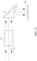
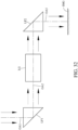
- Fig. 30 shows a schematic view of a configuration of a light-folding element in a photographing lens system according to one embodiment of the present disclosure
- Fig. 31 shows a schematic view of another configuration of a light-folding element in a photographing lens system according to one embodiment of the present disclosure.
- the photographing lens system can have, in order from an imaged object (not shown in the figures) to an image surface IMG along an optical path, a first optical axis OA1, a light-folding element LF and a second optical axis OA2.
- the light-folding element LF can be disposed between the imaged object and a lens group LG of the photographing lens system as shown in Fig. 30 or disposed between a lens group LG of the photographing lens system and the image surface IMG as shown in Fig. 31 .
- Fig. 32 shows a schematic view of a configuration of two light-folding elements in a photographing lens system according to one embodiment of the present disclosure. In Fig.
- the photographing lens system can have, in order from an imaged object (not shown in the figure) to an image surface IMG along an optical path, a first optical axis OA1, a first light-folding element LF1, a second optical axis OA2, a second light-folding element LF2 and a third optical axis OA3.
- the first light-folding element LF1 is disposed between the imaged object and a lens group LG of the photographing lens system
- the second light-folding element LF2 is disposed between the lens group LG of the photographing lens system and the image surface IMG
- the travelling direction of light on the first optical axis OA1 can be the same direction as the travelling direction of light on the third optical axis OA3 as shown in Fig. 32 .
- the photographing lens system can be optionally provided with three or more light-folding elements, and the present disclosure is not limited to the type, amount and position of the light-folding elements of the embodiments disclosed in the aforementioned figures.
- the photographing lens system can include at least one stop, such as an aperture stop, a glare stop or a field stop. Said glare stop or said field stop is set for eliminating the stray light and thereby improving image quality thereof.
- an aperture stop can be configured as a front stop or a middle stop.
- a front stop disposed between an imaged object and the first lens element can provide a longer distance between an exit pupil of the photographing lens system and the image surface to produce a telecentric effect, and thereby improves the image-sensing efficiency of an image sensor (for example, CCD or CMOS).
- a middle stop disposed between the first lens element and the image surface is favorable for enlarging the viewing angle of the photographing lens system and thereby provides a wider field of view for the same.
- the photographing lens system can include an aperture control unit.
- the aperture control unit may be a mechanical component or a light modulator, which can control the size and shape of the aperture through electricity or electrical signals.
- the mechanical component can include a movable member, such as a blade assembly or a light shielding sheet.
- the light modulator can include a shielding element, such as a filter, an electrochromic material or a liquid-crystal layer.
- the aperture control unit controls the amount of incident light or exposure time to enhance the capability of image quality adjustment.
- the aperture control unit can be the aperture stop of the present disclosure, which changes the f-number to obtain different image effects, such as the depth of field or lens speed.
- the object side and image side are defined in accordance with the direction of the optical axis, and the axial parameters are calculated along the optical axis. Furthermore, if the optical axis is folded by a light-folding element (e.g., a flat mirror and a prism), the axial parameters are also calculated along the folded optical axis.
- a light-folding element e.g., a flat mirror and a prism
- the i-th lens element counted from the object side in one lens group refers to the i-th lens element counted from the object side to the image side along the optical axis among all lens elements in the lens group
- the i-th lens element counted from the image side in one lens group refers to the i-th lens element counted from the image side to the object side along the optical axis among all lens elements in the lens group.
- Similar parameters include TGf (i.e., the axial distance between the object-side surface of the first lens element counted from the object side in the front lens group and the image-side surface of the first lens element counted from the image side in the front lens group), Tfflff2 (i.e., the axial distance between the image-side surface of the first lens element counted from the object side in the front lens group and the object-side surface of the second lens element counted from the object side in the front lens group), and TL (i.e., the axial distance between the object-side surface of the first lens element counted from the object side in the front lens group and the image surface).
- TGf i.e., the axial distance between the object-side surface of the first lens element counted from the object side in the front lens group and the image-side surface of the first lens element counted from the image side in the front lens group
- Tfflff2 i.e., the axial distance between the image-side surface
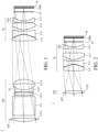
- Fig. 1 is a schematic view of an image capturing unit when a photographing lens system is in a first optical path state according to the 1st embodiment of the present disclosure.
- Fig. 2 is a schematic view of the image capturing unit when the photographing lens system is in a second optical path state according to the 1st embodiment.
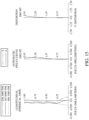
- Fig. 3 shows, in order from left to right, spherical aberration curves, astigmatic field curves and a distortion curve of the image capturing unit when the photographing lens system is in the first optical path state according to the 1st embodiment.
- Fig. 1 is a schematic view of an image capturing unit when a photographing lens system is in a first optical path state according to the 1st embodiment of the present disclosure.
- Fig. 2 is a schematic view of the image capturing unit when the photographing lens system is in a second optical path state according to the 1st embodiment.
- Fig. 3 shows, in order from left to right, spherical aberration curves, astig
- the image capturing unit 1 includes the photographing lens system (its reference numeral is omitted) of the present disclosure and an image sensor IS.
- the photographing lens system includes a first front lens group Gf1, a second front lens group Gf2, a rear lens group Gr and an optical path switching mechanism.
- the optical path switching mechanism is configured for the photographing lens system to be switched between a first optical path state and a second optical path state. As shown in Fig.
- the photographing lens system when the photographing lens system is in the first optical path state, the photographing lens system includes, in order from an object side to an image side along a first optical path, the first front lens group Gf1 and the rear lens group Gr.
- the photographing lens system when the photographing lens system is in the second optical path state, the photographing lens system includes, in order from the object side to the image side along a second optical path, the second front lens group Gf2 and the rear lens group Gr.
- the first front lens group Gf1 includes four lens elements which are, in order from the object side to the image side along the first optical path, a first front group first lens element Lf11, a first front group second lens element Lf12, a first front group third lens element Lf13 and a first front group fourth lens element Lf14, and there is no additional lens element disposed between each of the adjacent four lens elements.
- the second front lens group Gf2 includes one lens element which is a second front group first lens element Lf21.
- the rear lens group Gr includes four lens elements which are, in order from the object side to the image side along the optical path, a rear group first lens element Lr1, a rear group second lens element Lr2, a rear group third lens element Lr3 and a rear group fourth lens element Lr4, and there is no additional lens element disposed between each of the adjacent four lens elements.
- the rear lens group Gr includes a movable lens subgroup Gm, and the movable lens subgroup Gm can be moved along an optical axis when the photographing lens system is switched between the first optical path state and the second optical path state.
- the movable lens subgroup Gm includes one lens element, which is the rear group fourth lens element Lr4, and the movable lens subgroup Gm has negative refractive power.
- the movable lens subgroup Gm is moved towards the image side along the optical axis.
- the photographing lens system further includes an aperture stop ST1, a prism E1, a stop S1, an aperture stop ST2, a filter E3 and an image surface IMG.
- the photographing lens system when the photographing lens system is in the first optical path state, the photographing lens system includes, in order from the object side to the image side along the first optical path, the aperture stop ST1, the first front group first lens element Lf11, the prism E1, the first front group second lens element Lf12, the first front group third lens element Lf13, the stop S1, the first front group fourth lens element Lf14, the rear group first lens element Lr1, the rear group second lens element Lr2, the rear group third lens element Lr3, the rear group fourth lens element Lr4, the filter E3 and the image surface IMG.
- the photographing lens system when the photographing lens system is in the second optical path state, includes, in order from the object side to the image side along the second optical path, the aperture stop ST2, the second front group first lens element Lf21, the rear group first lens element Lr1, the rear group second lens element Lr2, the rear group third lens element Lr3, the rear group fourth lens element Lr4, the filter E3 and the image surface IMG.
- each of the optical paths of the image capturing unit 1 can be folded by a reflector (e.g., the prism E1, a reflection mirror E2, a reflection mirror E2b, or a prism E2c).
- a reflector e.g., the prism E1, a reflection mirror E2, a reflection mirror E2b, or a prism E2c.
- the prism E1 is configured to reflect incident light rays so that the first optical path is folded at the prism E1
- the reflection mirror E2 is configured to reflect incident light rays so that the second optical path is folded at the reflection mirror E2.
- FIG. 5 is a schematic view of a first optical path being folded by a reflector in the image capturing unit according to the 1st embodiment.
- the prism E1 is made of glass material and has a reflection surface E1S
- the prism E1 is disposed in the first front lens group Gf1
- the first optical path is folded by the reflection surface E1S of the prism E1.
- Fig. 6 is a schematic view of one example of a second optical path being folded by a reflector in the image capturing unit according to the 1st embodiment.
- Fig. 5 the prism E1 is made of glass material and has a reflection surface E1S
- the prism E1 is disposed in the first front lens group Gf1
- the first optical path is folded by the reflection surface E1S of the prism E1.
- Fig. 6 is a schematic view of one example of a second optical path being folded by a reflector in the image capturing unit according to the 1st embodiment. As shown in Fig.
- the reflection mirror E2 is a flat mirror having a reflection surface E2S
- the reflection mirror E2 is disposed between the second front lens group Gf2 and the rear lens group Gr
- the second optical path is folded by the reflection surface E2S of the reflection mirror E2.
- Fig. 7 is a schematic view of another example of the second optical path being folded by a reflector in the image capturing unit according to the 1st embodiment.
- the reflection mirror E2b is a flat mirror having a reflection surface
- the reflection mirror E2 is disposed on the object side of the second front lens group Gf2
- the second optical path is folded by the reflection surface of the reflection mirror E2b.
- FIG. 8 is a schematic view of another example of the second optical path being folded by a reflector in the image capturing unit according to the 1st embodiment.
- the prism E2c has a reflection surface
- the prism E2c is disposed on the object side of the second front lens group Gf2
- the second optical path is folded by the reflection surface of the prism E2c.
- the type, number and arrangement of components configured to fold the optical path can be altered according to actual requirements, and the present disclosure is not limited thereto.
- the arrangement of the optical path switching mechanism can be similar to the configurations as shown in Fig. 26 to Fig. 29 .
- the optical path switching mechanism can include at least one reflector (e.g., the reflection mirror E2, the reflection mirror E2b or the prism E2c) which is movable or rotatable relative to the first front lens group Gf1, the second front lens group Gf2 or the rear lens group Gr.
- the reflection mirror E2b the reflection mirror E2b or the prism E2c
- the optical path switching mechanism includes the reflection mirror E2, which is a flat mirror having the reflection surface E2S, and the reflection mirror E2 is movable or rotatable relative to the first front lens group Gf1, the second front lens group Gf2, the rear lens group Gr or the image sensor IS, so that the optical path switching mechanism enables the photographing lens system to be switched between the first optical path state and the second optical path state by moving or rotating the reflection mirror E2.
- the reflection mirror E2 of the optical path switching mechanism is located between the second front lens group Gf2 and the rear lens group Gr in the second optical path, and the second optical path is folded by the reflection mirror E2.
- the optical path switching mechanism enables the photographing lens system to be switched from the first optical path state to the second optical path state by moving or rotating the reflection mirror E2 to a position between the second front lens group Gf2 and the rear lens group Gr in the second optical path, or enables the photographing lens system to be switched from the second optical path state to the first optical path state by moving or rotating the reflection mirror E2 away from the position between the second front lens group Gf2 and the rear lens group.
- the optical path switching mechanism includes the reflection mirror E2b and the second front lens group Gf2.
- the reflection mirror E2b is located on the object side of the second front lens group Gf2 in the second optical path, and the reflection mirror E2b is a flat mirror having a reflection surface.
- the reflection mirror E2b and the second front lens group Gf2 of the optical path switching mechanism are movable or rotatable relative to the first front lens group Gf1, the rear lens group Gr and the image sensor IS, so that the optical path switching mechanism enables the photographing lens system to be switched between the first optical path state and the second optical path state by moving or rotating the reflection mirror E2b and the second front lens group Gf2.
- the optical path switching mechanism enables the photographing lens system to be switched from the first optical path state to the second optical path state by moving or rotating the reflection mirror E2b and the second front lens group Gf2 to a position between the first front lens group Gf1 and the rear lens group Gr, or enables the photographing lens system to be switched from the second optical path state to the first optical path state by moving or rotating the reflection mirror E2b and the second front lens group Gf2 away from the position between the first front lens group Gf1 and the rear lens group Gr.
- the optical path switching mechanism in Fig. 8 is similar to the optical path switching mechanism in Fig. 7 , and they are different from each other in that the reflector (i.e., the prism E2c) of the optical path switching mechanism in Fig.
- the optical path switching mechanism includes the prism E2c and the second front lens group Gf2.
- the prism E2c is located on the object side of the second front lens group Gf2 in the second optical path, and the prism E2c is a prism having a reflection surface.
- the prism E2c and the second front lens group Gf2 of the optical path switching mechanism are movable or rotatable relative to the first front lens group Gf1, the rear lens group Gr and the image sensor IS, so that the optical path switching mechanism enables the photographing lens system to be switched between the first optical path state and the second optical path state by moving or rotating the prism E2c and the second front lens group Gf2.
- the type, number and arrangement of components included in the optical path switching mechanism can be altered according to actual requirements, and the present disclosure is not limited thereto.
- the first front group first lens element Lf11 with positive refractive power has an object-side surface being convex in a paraxial region thereof and an image-side surface being convex in a paraxial region thereof.
- the first front group first lens element Lf11 is made of plastic material and has the object-side surface and the image-side surface being both aspheric.
- the first front group second lens element Lf12 with negative refractive power has an object-side surface being convex in a paraxial region thereof and an image-side surface being concave in a paraxial region thereof.
- the first front group second lens element Lf12 is made of plastic material and has the object-side surface and the image-side surface being both aspheric.
- the first front group third lens element Lf13 with negative refractive power has an object-side surface being convex in a paraxial region thereof and an image-side surface being concave in a paraxial region thereof.
- the first front group third lens element Lf13 is made of plastic material and has the object-side surface and the image-side surface being both aspheric.
- the first front group fourth lens element Lf14 with positive refractive power has an object-side surface being concave in a paraxial region thereof and an image-side surface being convex in a paraxial region thereof.
- the first front group fourth lens element Lf14 is made of plastic material and has the object-side surface and the image-side surface being both aspheric.
- the second front group first lens element Lf21 with positive refractive power has an object-side surface being convex in a paraxial region thereof and an image-side surface being planar in a paraxial region thereof.
- the second front group first lens element Lf21 is made of plastic material and has the object-side surface and the image-side surface being both aspheric.
- the rear group first lens element Lr1 with positive refractive power has an object-side surface being convex in a paraxial region thereof and an image-side surface being convex in a paraxial region thereof.
- the rear group first lens element Lr1 is made of plastic material and has the object-side surface and the image-side surface being both aspheric.
- the rear group second lens element Lr2 with negative refractive power has an object-side surface being concave in a paraxial region thereof and an image-side surface being convex in a paraxial region thereof.
- the rear group second lens element Lr2 is made of plastic material and has the object-side surface and the image-side surface being both aspheric.
- the rear group third lens element Lr3 with positive refractive power has an object-side surface being convex in a paraxial region thereof and an image-side surface being concave in a paraxial region thereof.
- the rear group third lens element Lr3 is made of plastic material and has the object-side surface and the image-side surface being both aspheric.
- the rear group fourth lens element Lr4 with negative refractive power has an object-side surface being concave in a paraxial region thereof and an image-side surface being convex in a paraxial region thereof.
- the rear group fourth lens element Lr4 is made of plastic material and has the object-side surface and the image-side surface being both aspheric.
- the object-side surface of the rear group fourth lens element Lr4 has one critical point in an off-axis region thereof.
- the filter E3 is made of glass material and located between the rear group fourth lens element Lr4 and the image surface IMG, and will not affect the focal length of the photographing lens system.
- the image sensor IS is disposed on or near the image surface IMG of the photographing lens system.
- a focal length of the photographing lens system is F
- a focal length of the front lens group i.e., the first front lens group Gf1 or the second front lens group Gf2
- FGf a focal length of the front lens group
- FGr a focal length of the rear lens group
- an f-number of the photographing lens system is Fno
- half of a maximum field of view of the photographing lens system is HFOV.
- front lens group refers to the first front lens group Gf1 when the photographing lens system is in the first optical path state, and refers to the second front lens group Gf2 when the photographing lens system is in the second optical path state.
- optical path refers to the first optical path when the photographing lens system is in the first optical path state, and refers to the second optical path when the photographing lens system is in the second optical path state.
- An axial distance between the object-side surface of the first lens element counted from the object side in the front lens group and the image-side surface of the first lens element counted from the image side in the front lens group is TGf.
- An axial distance between the object-side surface of the first lens element counted from the object side in the rear lens group Gr and the image-side surface of the first lens element counted from the image side in the rear lens group Gr is TGr.
- An axial distance between the image-side surface of the first lens element counted from the object side in the front lens group and the object-side surface of the second lens element counted from the object side in the front lens group is Tfflff2.
- a central thickness of the first lens element counted from the image side in the front lens group is Tfr1.
- the axial distance between the image-side surface of the first front group fourth lens element Lf14 and the object-side surface of the rear group first lens element Lr1 is TGfGr
- the central thickness of the first front group fourth lens element Lf14 is Tfrl
- the axial distance between the image-side surface of the second front group first lens element Lf21 and the object-side surface of the rear group first lens element Lr1 is TGfGr
- the central thickness of the second front group first lens element Lf21 is Tfrl
- An axial distance between the object-side surface of the first lens element counted from the object side in the front lens group and the image surface IMG is TL.
- a focal length of the first lens element counted from the object side in the front lens group is Fff1
- a central thickness of the first lens element counted from the object side in the front lens group is Tff1.
- the focal length of the second front group first lens element Lf21 is Fff1
- the central thickness of the second front group first lens element Lf21 is Tff1
- Fff1/Tff1 21.28.
- a focal length of the first lens element counted from the image side in the front lens group is Ffrl
- a focal length of the second lens element counted from the image side in the front lens group is Ffr2.
- 0.28.
- the focal length of the second front lens group Gf2 is FGf
- the focal length of the rear lens group Gr is FGr
- 0.38.
- An entrance pupil diameter of the photographing lens system is EPD
- a maximum effective radius of the object-side surface of the first lens element counted from the object side in the front lens group is Yfflf.
- the entrance pupil diameter of the photographing lens system is EPD
- a maximum image height of the photographing lens system is ImgH.
- the maximum effective radius of the object-side surface of the first front group first lens element Lf11 is Yfflf
- the maximum image height of the photographing lens system is ImgH
- the maximum effective radius of the object-side surface of the second front group first lens element Lf21 is Yfflf
- a maximum effective radius of the image-side surface of the first lens element counted from the image side in the front lens group is Yfrlr.
- the maximum effective radius of the object-side surface of the second front group first lens element Lf21 is Yfflf
- the maximum effective radius of the image-side surface of the second front group first lens element Lf21 is Yfrlr
- a maximum effective radius of the image-side surface of the first lens element counted from the image side in the rear lens group Gr is Yrrlr.
- the maximum effective radius of the object-side surface of the second front group first lens element Lf21 is Yfflf
- the maximum effective radius of the image-side surface of the rear group fourth lens element Lr4 Yrrlr
- a maximum effective radius of the object-side surface of the first lens element counted from the object side in the rear lens group Gr is Yrflf.
- the maximum effective radius of the object-side surface of the rear group first lens element Lr1 is Yrflf
- the maximum effective radius of the object-side surface of the rear group first lens element Lr1 is Yrflf
- the maximum effective radius of the image-side surface of the rear group fourth lens element Lr4 Yrrlr
- a maximum value among maximum effective radii of all lens surfaces of lens elements in the photographing lens system is Ymax, and a minimum value among maximum effective radii of all lens surfaces of lens elements in the photographing lens system is Ymin.
- Ymax/Ymin 1.28.
- Ymax/Ymin 1.27.
- a vertical distance between a non-axial critical point on the object-side surface of the first lens element counted from the image side in the rear lens group and the optical axis is YCrrlf, and a maximum effective radius of the object-side surface of the first lens element counted from the image side of the rear lens group Gr is Yrrlf.
- the vertical distance between the non-axial critical point on the object-side surface of the rear group fourth lens element Lr4 and the optical axis is YCrrlf
- the maximum effective radius of the object-side surface of the rear group fourth lens element Lr4 is Yrrlf
- the vertical distance between the non-axial critical point on the object-side surface of the rear group fourth lens element Lr4 and the optical axis is YCrrlf
- the maximum effective radius of the object-side surface of the rear group fourth lens element Lr4 is Yrrlf
- An Abbe number of the first lens element counted from the object side in the rear lens group Gr is Vrfl
- an Abbe number of the second lens element counted from the object side in the rear lens group Gr is Vrf2
- an Abbe number of the second lens element counted from the image side in the rear lens group Gr is Vrr2
- an Abbe number of the first lens element counted from the image side in the rear lens group Gr is Vrr1.
- the Abbe number of the rear group first lens element Lr1 is Vrfl
- the Abbe number of the rear group second lens element Lr2 is Vrf2
- the Abbe number of the rear group third lens element Lr3 is Vrr2
- the Abbe number of the rear group fourth lens element Lr4 is Vrr1
- minVGr 19.5.
- the Abbe number of the rear group second lens element Lr2 and the Abbe number of the rear group third lens element Lr3 are the same and smaller than the Abbe numbers of the other lens elements in the rear lens group Gr, and minVGr is equal to the Abbe number of the rear group second lens element Lr2 and the Abbe number of the rear group third lens element Lr3.
- a focal length of the first lens element counted from the object side in the rear lens group Gr is Frfl
- a focal length of the second lens element counted from the object side in the rear lens group Gr is Frf2
- a focal length of the second lens element counted from the image side in the rear lens group Gr is Frr2
- a focal length of the first lens element counted from the image side in the rear lens group Gr is Frr1.
- the focal length of the rear group first lens element Lr1 is Frfl
- the focal length of the rear group second lens element Lr2 is Frf2
- the focal length of the rear group third lens element Lr3 is Frr2
- the focal length of the rear group fourth lens element Lr4 is Frr1
- a focal length of the photographing lens system in the first optical path state is FS1
- a focal length of the photographing lens system in the second optical path state is FS2
- An effective radius of the stop S1 (Surface Gf1-S10) is 2.900 mm.
- the reflector is disposed in the first front lens group Gf1.
- the reflector is the prism E1 having the reflection surface E1S.
- F 12.23 mm
- Fno 2.45
- HFOV 13.5 deg.
- a reflector (e.g., E2, E2b or E2c) is further included.
- the reflector can be disposed between the second front lens group Gf2 and the rear lens group Gr.
- the reflector can be disposed on the object side of the second front lens group Gf2.
- the reflector is a prism or a flat mirror having a reflection surface.
- the photographing lens system is in the first optical path state, the curvature radius, the thickness and the focal length are shown in millimeters (mm), and surface numbers O-S0 to O-S3 represent the surfaces sequentially arranged from the object side to the image side along the first optical axis.
- the photographing lens system is in the second optical path state, the curvature radius, the thickness and the focal length are shown in millimeters, and surface numbers O-S0 to O-S3 represent the surfaces sequentially arranged from the object side to the image side along the second optical axis.
- k represents the conic coefficient of the equation of the aspheric surface profiles.
- A4-A22 represent the aspheric coefficients ranging from the 4th order to the 22nd order.
- Fig. 9 is a schematic view of an image capturing unit when a photographing lens system is in a first optical path state according to the 2nd embodiment of the present disclosure.
- Fig. 10 is a schematic view of the image capturing unit when the photographing lens system is in a second optical path state according to the 2nd embodiment.
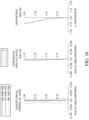
- Fig. 11 shows, in order from left to right, spherical aberration curves, astigmatic field curves and a distortion curve of the image capturing unit when the photographing lens system is in the first optical path state according to the 2nd embodiment.
- Fig. 9 is a schematic view of an image capturing unit when a photographing lens system is in a first optical path state according to the 2nd embodiment of the present disclosure.
- Fig. 10 is a schematic view of the image capturing unit when the photographing lens system is in a second optical path state according to the 2nd embodiment.
- Fig. 11 shows, in order from left to right, spherical aberration curves, astigmatic field curves and
- the image capturing unit 2 includes the photographing lens system (its reference numeral is omitted) of the present disclosure and an image sensor IS.
- the photographing lens system includes a first front lens group Gf1, a second front lens group Gf2, a rear lens group Gr and an optical path switching mechanism.
- the optical path switching mechanism is configured for the photographing lens system to be switched between a first optical path state and a second optical path state. As shown in Fig.
- the photographing lens system when the photographing lens system is in the first optical path state, the photographing lens system includes, in order from an object side to an image side along a first optical path, the first front lens group Gf1 and the rear lens group Gr. As shown in Fig. 10 , when the photographing lens system is in the second optical path state, the photographing lens system includes, in order from the object side to the image side along a second optical path, the second front lens group Gf2 and the rear lens group Gr.
- the first front lens group Gf1 includes four lens elements which are, in order from the object side to the image side along the first optical path, a first front group first lens element Lf11, a first front group second lens element Lf12, a first front group third lens element Lf13 and a first front group fourth lens element Lf14, and there is no additional lens element disposed between each of the adjacent four lens elements.
- the second front lens group Gf2 includes one lens element which is a second front group first lens element Lf21.
- the rear lens group Gr includes four lens elements which are, in order from the object side to the image side along the optical path, a rear group first lens element Lr1, a rear group second lens element Lr2, a rear group third lens element Lr3 and a rear group fourth lens element Lr4, and there is no additional lens element disposed between each of the adjacent four lens elements.
- the rear lens group Gr includes a movable lens subgroup Gm, and the movable lens subgroup Gm can be moved along an optical axis when the photographing lens system is switched between the first optical path state and the second optical path state.
- the movable lens subgroup Gm includes one lens element, which is the rear group fourth lens element Lr4, and the movable lens subgroup Gm has negative refractive power.
- the movable lens subgroup Gm is moved towards the image side along the optical axis.
- the photographing lens system further includes an aperture stop ST1, a prism E1, a stop S1, an aperture stop ST2, a filter E3 and an image surface IMG.
- the photographing lens system when the photographing lens system is in the first optical path state, the photographing lens system includes, in order from the object side to the image side along the first optical path, the aperture stop ST1, the first front group first lens element Lf11, the prism E1, the first front group second lens element Lf12, the first front group third lens element Lf13, the stop S1, the first front group fourth lens element Lf14, the rear group first lens element Lr1, the rear group second lens element Lr2, the rear group third lens element Lr3, the rear group fourth lens element Lr4, the filter E3 and the image surface IMG.
- the photographing lens system when the photographing lens system is in the second optical path state, includes, in order from the object side to the image side along the second optical path, the aperture stop ST2, the second front group first lens element Lf21, the rear group first lens element Lr1, the rear group second lens element Lr2, the rear group third lens element Lr3, the rear group fourth lens element Lr4, the filter E3 and the image surface IMG.
- the prism E1 is made of glass material and has a reflection surface, the prism E1 is disposed in the first front lens group Gf1, and the first optical path is folded by the reflection surface of the prism E1.
- the optical paths respectively shown in Fig. 9 and Fig. 10 are not folded by a reflector (e.g., the prism E1).
- the arrangement of light-folding element(s) of the image capturing unit 2 can be similar to the configurations as shown in Fig. 5 to Fig. 8 of the 1st embodiment, and the arrangement of the optical path switching mechanism can be similar to the configurations as shown in Fig. 26 to Fig. 29 , and the present disclosure is not limited thereto.
- the first front group first lens element Lf11 with positive refractive power has an object-side surface being convex in a paraxial region thereof and an image-side surface being concave in a paraxial region thereof.
- the first front group first lens element Lf11 is made of plastic material and has the object-side surface and the image-side surface being both aspheric.
- the first front group second lens element Lf12 with positive refractive power has an object-side surface being convex in a paraxial region thereof and an image-side surface being convex in a paraxial region thereof.
- the first front group second lens element Lf12 is made of plastic material and has the object-side surface and the image-side surface being both aspheric.
- the first front group third lens element Lf13 with negative refractive power has an object-side surface being concave in a paraxial region thereof and an image-side surface being concave in a paraxial region thereof.
- the first front group third lens element Lf13 is made of plastic material and has the object-side surface and the image-side surface being both aspheric.
- the first front group fourth lens element Lf14 with positive refractive power has an object-side surface being concave in a paraxial region thereof and an image-side surface being convex in a paraxial region thereof.
- the first front group fourth lens element Lf14 is made of plastic material and has the object-side surface and the image-side surface being both aspheric.
- the second front group first lens element Lf21 with positive refractive power has an object-side surface being convex in a paraxial region thereof and an image-side surface being concave in a paraxial region thereof.
- the second front group first lens element Lf21 is made of plastic material and has the object-side surface and the image-side surface being both aspheric.
- the rear group first lens element Lr1 with positive refractive power has an object-side surface being convex in a paraxial region thereof and an image-side surface being convex in a paraxial region thereof.
- the rear group first lens element Lr1 is made of plastic material and has the object-side surface and the image-side surface being both aspheric.
- the rear group second lens element Lr2 with negative refractive power has an object-side surface being concave in a paraxial region thereof and an image-side surface being convex in a paraxial region thereof.
- the rear group second lens element Lr2 is made of plastic material and has the object-side surface and the image-side surface being both aspheric.
- the rear group third lens element Lr3 with positive refractive power has an object-side surface being convex in a paraxial region thereof and an image-side surface being concave in a paraxial region thereof.
- the rear group third lens element Lr3 is made of plastic material and has the object-side surface and the image-side surface being both aspheric.
- the rear group fourth lens element Lr4 with negative refractive power has an object-side surface being concave in a paraxial region thereof and an image-side surface being convex in a paraxial region thereof.
- the rear group fourth lens element Lr4 is made of plastic material and has the object-side surface and the image-side surface being both aspheric.
- the object-side surface of the rear group fourth lens element Lr4 has one critical point in an off-axis region thereof.
- the filter E3 is made of glass material and located between the rear group fourth lens element Lr4 and the image surface IMG, and will not affect the focal length of the photographing lens system.
- the image sensor IS is disposed on or near the image surface IMG of the photographing lens system.
- An effective radius of the stop S1 (Surface Gf1-S10) is 2.880 mm.
- the reflector is disposed in the first front lens group Gf1.
- the reflector is the prism E1 having a reflection surface.
- a reflector can be further included.
- the reflector can be disposed between the second front lens group Gf2 and the rear lens group Gr.
- the reflector can be disposed on the object side of the second front lens group Gf2.
- the reflector is a prism or a flat mirror having a reflection surface.
- the equation of the aspheric surface profiles of the aforementioned lens elements is the same as the equation of the 1st embodiment. Also, the definitions of these parameters shown in the following table are the same as those stated in the 1st embodiment with corresponding values for the 2nd embodiment, so an explanation in this regard will not be provided again.
- Fig. 13 is a schematic view of an image capturing unit when a photographing lens system is in a first optical path state according to the 3rd embodiment of the present disclosure.
- Fig. 14 is a schematic view of the image capturing unit when the photographing lens system is in a second optical path state according to the 3rd embodiment.
- Fig. 15 shows, in order from left to right, spherical aberration curves, astigmatic field curves and a distortion curve of the image capturing unit when the photographing lens system is in the first optical path state according to the 3rd embodiment.
- Fig. 13 is a schematic view of an image capturing unit when a photographing lens system is in a first optical path state according to the 3rd embodiment of the present disclosure.
- Fig. 14 is a schematic view of the image capturing unit when the photographing lens system is in a second optical path state according to the 3rd embodiment.
- Fig. 15 shows, in order from left to right, spherical aberration curves, astig
- the image capturing unit 3 includes the photographing lens system (its reference numeral is omitted) of the present disclosure and an image sensor IS.
- the photographing lens system includes a first front lens group Gf1, a second front lens group Gf2, a rear lens group Gr and an optical path switching mechanism.
- the optical path switching mechanism is configured for the photographing lens system to be switched between a first optical path state and a second optical path state. As shown in Fig.
- the photographing lens system when the photographing lens system is in the first optical path state, the photographing lens system includes, in order from an object side to an image side along a first optical path, the first front lens group Gf1 and the rear lens group Gr.
- the photographing lens system when the photographing lens system is in the second optical path state, the photographing lens system includes, in order from the object side to the image side along a second optical path, the second front lens group Gf2 and the rear lens group Gr.
- the first front lens group Gf1 includes four lens elements which are, in order from the object side to the image side along the first optical path, a first front group first lens element Lf11, a first front group second lens element Lf12, a first front group third lens element Lf13 and a first front group fourth lens element Lf14, and there is no additional lens element disposed between each of the adjacent four lens elements.
- the second front lens group Gf2 includes one lens element which is a second front group first lens element Lf21.
- the rear lens group Gr includes four lens elements which are, in order from the object side to the image side along the optical path, a rear group first lens element Lr1, a rear group second lens element Lr2, a rear group third lens element Lr3 and a rear group fourth lens element Lr4, and there is no additional lens element disposed between each of the adjacent four lens elements.
- the rear lens group Gr includes a movable lens subgroup Gm, and the movable lens subgroup Gm can be moved along an optical axis when the photographing lens system is switched between the first optical path state and the second optical path state.
- the movable lens subgroup Gm includes one lens element, which is the rear group fourth lens element Lr4, and the movable lens subgroup Gm has negative refractive power.
- the movable lens subgroup Gm is moved towards the image side along the optical axis.
- the photographing lens system further includes an aperture stop ST1, a prism E1, a stop S1, an aperture stop ST2, a filter E3 and an image surface IMG.
- the photographing lens system when the photographing lens system is in the first optical path state, the photographing lens system includes, in order from the object side to the image side along the first optical path, the aperture stop ST1, the first front group first lens element Lf11, the prism E1, the first front group second lens element Lf12, the first front group third lens element Lf13, the stop S1, the first front group fourth lens element Lf14, the rear group first lens element Lr1, the rear group second lens element Lr2, the rear group third lens element Lr3, the rear group fourth lens element Lr4, the filter E3 and the image surface IMG.
- the photographing lens system when the photographing lens system is in the second optical path state, includes, in order from the object side to the image side along the second optical path, the aperture stop ST2, the second front group first lens element Lf21, the rear group first lens element Lr1, the rear group second lens element Lr2, the rear group third lens element Lr3, the rear group fourth lens element Lr4, the filter E3 and the image surface IMG.
- the prism E1 is made of glass material and has a reflection surface, the prism E1 is disposed in the first front lens group Gf1, and the first optical path is folded by the reflection surface of the prism E1.
- the optical paths respectively shown in Fig. 13 and Fig. 14 are not folded by a reflector (e.g., the prism E1).
- the arrangement of light-folding element(s) of the image capturing unit 3 can be similar to the configurations as shown in Fig. 5 to Fig. 8 of the 1st embodiment, and the arrangement of the optical path switching mechanism can be similar to the configurations as shown in Fig. 26 to Fig. 29 , and the present disclosure is not limited thereto.
- the first front group first lens element Lf11 with positive refractive power has an object-side surface being convex in a paraxial region thereof and an image-side surface being convex in a paraxial region thereof.
- the first front group first lens element Lf11 is made of plastic material and has the object-side surface and the image-side surface being both aspheric.
- the first front group second lens element Lf12 with negative refractive power has an object-side surface being concave in a paraxial region thereof and an image-side surface being concave in a paraxial region thereof.
- the first front group second lens element Lf12 is made of plastic material and has the object-side surface and the image-side surface being both aspheric.
- the first front group third lens element Lf13 with negative refractive power has an object-side surface being convex in a paraxial region thereof and an image-side surface being concave in a paraxial region thereof.
- the first front group third lens element Lf13 is made of plastic material and has the object-side surface and the image-side surface being both aspheric.
- the first front group fourth lens element Lf14 with positive refractive power has an object-side surface being concave in a paraxial region thereof and an image-side surface being convex in a paraxial region thereof.
- the first front group fourth lens element Lf14 is made of plastic material and has the object-side surface and the image-side surface being both aspheric.
- the second front group first lens element Lf21 with positive refractive power has an object-side surface being convex in a paraxial region thereof and an image-side surface being convex in a paraxial region thereof.
- the second front group first lens element Lf21 is made of plastic material and has the object-side surface and the image-side surface being both aspheric.
- the rear group first lens element Lr1 with positive refractive power has an object-side surface being convex in a paraxial region thereof and an image-side surface being convex in a paraxial region thereof.
- the rear group first lens element Lr1 is made of glass material and has the object-side surface and the image-side surface being both aspheric.
- the rear group second lens element Lr2 with negative refractive power has an object-side surface being concave in a paraxial region thereof and an image-side surface being convex in a paraxial region thereof.
- the rear group second lens element Lr2 is made of plastic material and has the object-side surface and the image-side surface being both aspheric.
- the rear group third lens element Lr3 with positive refractive power has an object-side surface being convex in a paraxial region thereof and an image-side surface being concave in a paraxial region thereof.
- the rear group third lens element Lr3 is made of plastic material and has the object-side surface and the image-side surface being both aspheric.
- the rear group fourth lens element Lr4 with negative refractive power has an object-side surface being concave in a paraxial region thereof and an image-side surface being convex in a paraxial region thereof.
- the rear group fourth lens element Lr4 is made of plastic material and has the object-side surface and the image-side surface being both aspheric.
- the object-side surface of the rear group fourth lens element Lr4 has one critical point in an off-axis region thereof.
- the filter E3 is made of glass material and located between the rear group fourth lens element Lr4 and the image surface IMG, and will not affect the focal length of the photographing lens system.
- the image sensor IS is disposed on or near the image surface IMG of the photographing lens system.
- An effective radius of the stop S1 (Surface Gf1-S10) is 2.890 mm.
- the reflector is disposed in the first front lens group Gf1.
- the reflector is the prism E1 having a reflection surface.
- F 12.85 mm
- Fno 2.57
- HFOV 13.0 deg.
- a reflector can be further included.
- the reflector can be disposed between the second front lens group Gf2 and the rear lens group Gr.
- the reflector can be disposed on the object side of the second front lens group Gf2.
- the reflector is a prism or a flat mirror having a reflection surface.
- the equation of the aspheric surface profiles of the aforementioned lens elements is the same as the equation of the 1st embodiment. Also, the definitions of these parameters shown in the following table are the same as those stated in the 1st embodiment with corresponding values for the 3rd embodiment, so an explanation in this regard will not be provided again.
- these parameters can be calculated from Table 7, Table 8 and Table 9 as the following values and satisfy the following conditions: 3rd Embodiment 1st optical path state 2nd optical path state 1st optical path state 2nd optical path state F [mm] 25.47 12.85 EPD/Yfflf 2.00 2.00 FGf [mm] 30.70 18.08 Yfflf/ImgH 1.20 0.85 FGr [mm] 334.88 83.77 Yfflf/Yfrlr 1.08 0.97 Fno 3.62 2.57 Yfflf/Yrrlr 1.22 0.91 HFOV [deg.] 6.5 13.0 Yrflf/Yrrlr 1.21 1.10 TGf [mm] 12.639 0.936 Ymax/Ymin 1.28 1.22 TGr [mm] 6.109 7.311 YCrrlf/Yrrlf 0.68 0.73 TGfGr [mm] 11.461 5.947 (Vrf1+Vr
- Fig. 17 is a schematic view of an image capturing unit when a photographing lens system is in a first optical path state according to the 4th embodiment of the present disclosure.
- Fig. 18 is a schematic view of the image capturing unit when the photographing lens system is in a second optical path state according to the 4th embodiment.
- Fig. 19 shows, in order from left to right, spherical aberration curves, astigmatic field curves and a distortion curve of the image capturing unit when the photographing lens system is in the first optical path state according to the 4th embodiment.
- Fig. 17 is a schematic view of an image capturing unit when a photographing lens system is in a first optical path state according to the 4th embodiment of the present disclosure.
- Fig. 18 is a schematic view of the image capturing unit when the photographing lens system is in a second optical path state according to the 4th embodiment.
- Fig. 19 shows, in order from left to right, spherical aberration curves, astigmatic field curves and
- the image capturing unit 4 includes the photographing lens system (its reference numeral is omitted) of the present disclosure and an image sensor IS.
- the photographing lens system includes a first front lens group Gf1, a second front lens group Gf2, a rear lens group Gr and an optical path switching mechanism (not shown in the figure).
- the optical path switching mechanism is configured for the photographing lens system to be switched between a first optical path state and a second optical path state. As shown in Fig.
- the photographing lens system when the photographing lens system is in the first optical path state, the photographing lens system includes, in order from an object side to an image side along a first optical path, the first front lens group Gf1 and the rear lens group Gr. As shown in Fig. 18 , when the photographing lens system is in the second optical path state, the photographing lens system includes, in order from the object side to the image side along a second optical path, the second front lens group Gf2 and the rear lens group Gr.
- the first front lens group Gf1 includes four lens elements which are, in order from the object side to the image side along the first optical path, a first front group first lens element Lf11, a first front group second lens element Lf12, a first front group third lens element Lf13 and a first front group fourth lens element Lf14, and there is no additional lens element disposed between each of the adjacent four lens elements.
- the second front lens group Gf2 includes one lens element which is a second front group first lens element Lf21.
- the rear lens group Gr includes four lens elements which are, in order from the object side to the image side along the optical path, a rear group first lens element Lr1, a rear group second lens element Lr2, a rear group third lens element Lr3 and a rear group fourth lens element Lr4, and there is no additional lens element disposed between each of the adjacent four lens elements.
- the rear lens group Gr includes a movable lens subgroup Gm, and the movable lens subgroup Gm can be moved along an optical axis when the photographing lens system is switched between the first optical path state and the second optical path state.
- the movable lens subgroup Gm includes one lens element, which is the rear group fourth lens element Lr4, and the movable lens subgroup Gm has negative refractive power.
- the movable lens subgroup Gm is moved towards the image side along the optical axis.
- the photographing lens system further includes an aperture stop ST1, a prism E1, a stop S1, an aperture stop ST2, a prism E4, a filter E3 and an image surface IMG.
- the photographing lens system when the photographing lens system is in the first optical path state, the photographing lens system includes, in order from the object side to the image side along the first optical path, the aperture stop ST1, the first front group first lens element Lf11, the prism E1, the first front group second lens element Lf12, the first front group third lens element Lf13, the stop S1, the first front group fourth lens element Lf14, the rear group first lens element Lr1, the rear group second lens element Lr2, the rear group third lens element Lr3, the rear group fourth lens element Lr4, the filter E3 and the image surface IMG.
- the photographing lens system when the photographing lens system is in the second optical path state, includes, in order from the object side to the image side along the second optical path, the aperture stop ST2, the second front group first lens element Lf21, the prism E4, the rear group first lens element Lr1, the rear group second lens element Lr2, the rear group third lens element Lr3, the rear group fourth lens element Lr4, the filter E3 and the image surface IMG.
- the prism E1 is made of glass material and has a reflection surface
- the prism E1 is disposed in the first front lens group Gf1, and the first optical path is folded by the reflection surface of the prism E1.
- the prism E4 is made of glass material and has a reflection surface
- the prism E4 is disposed between the second front lens group Gf2 and the rear lens group Gr, and the second optical path is folded by the reflection surface of the prism E4.
- the optical paths respectively shown in Fig. 17 and Fig. 18 are not folded by a reflector (e.g., the prism E1 and the prism E4).
- the arrangement of light-folding element(s) of the image capturing unit 4 can be similar to the configurations as shown in Fig. 5 to Fig. 8 of the 1st embodiment, and the arrangement of the optical path switching mechanism can be similar to the configurations as shown in Fig. 26 to Fig. 29 , and the present disclosure is not limited thereto.
- the first front group first lens element Lf11 with positive refractive power has an object-side surface being convex in a paraxial region thereof and an image-side surface being concave in a paraxial region thereof.
- the first front group first lens element Lf11 is made of plastic material and has the object-side surface and the image-side surface being both aspheric.
- the first front group second lens element Lf12 with positive refractive power has an object-side surface being concave in a paraxial region thereof and an image-side surface being convex in a paraxial region thereof.
- the first front group second lens element Lf12 is made of plastic material and has the object-side surface and the image-side surface being both aspheric.
- the first front group third lens element Lf13 with negative refractive power has an object-side surface being concave in a paraxial region thereof and an image-side surface being concave in a paraxial region thereof.
- the first front group third lens element Lf13 is made of plastic material and has the object-side surface and the image-side surface being both aspheric.
- the first front group fourth lens element Lf14 with positive refractive power has an object-side surface being concave in a paraxial region thereof and an image-side surface being convex in a paraxial region thereof.
- the first front group fourth lens element Lf14 is made of plastic material and has the object-side surface and the image-side surface being both aspheric.
- the second front group first lens element Lf21 with positive refractive power has an object-side surface being convex in a paraxial region thereof and an image-side surface being concave in a paraxial region thereof.
- the second front group first lens element Lf21 is made of plastic material and has the object-side surface and the image-side surface being both aspheric.
- the rear group first lens element Lr1 with positive refractive power has an object-side surface being convex in a paraxial region thereof and an image-side surface being convex in a paraxial region thereof.
- the rear group first lens element Lr1 is made of plastic material and has the object-side surface and the image-side surface being both aspheric.
- the rear group second lens element Lr2 with negative refractive power has an object-side surface being concave in a paraxial region thereof and an image-side surface being concave in a paraxial region thereof.
- the rear group second lens element Lr2 is made of plastic material and has the object-side surface and the image-side surface being both aspheric.
- the rear group third lens element Lr3 with positive refractive power has an object-side surface being convex in a paraxial region thereof and an image-side surface being convex in a paraxial region thereof.
- the rear group third lens element Lr3 is made of plastic material and has the object-side surface and the image-side surface being both aspheric.
- the rear group fourth lens element Lr4 with negative refractive power has an object-side surface being concave in a paraxial region thereof and an image-side surface being concave in a paraxial region thereof.
- the rear group fourth lens element Lr4 is made of plastic material and has the object-side surface and the image-side surface being both aspheric.
- the object-side surface of the rear group fourth lens element Lr4 has one critical point in an off-axis region thereof.
- the filter E3 is made of glass material and located between the rear group fourth lens element Lr4 and the image surface IMG, and will not affect the focal length of the photographing lens system.
- the image sensor IS is disposed on or near the image surface IMG of the photographing lens system.
- An effective radius of the stop S1 (Surface Gf1-S10) is 2.937 mm.
- the reflector is disposed in the first front lens group Gf1.
- the reflector is the prism E1 having a reflection surface.
- the reflector is disposed between the second front lens group Gf2 and the rear lens group Gr.
- the reflector is the prism E4 having a reflection surface.
- the equation of the aspheric surface profiles of the aforementioned lens elements is the same as the equation of the 1st embodiment. Also, the definitions of these parameters shown in the following table are the same as those stated in the 1st embodiment with corresponding values for the 4th embodiment, so an explanation in this regard will not be provided again.
- Fig. 21 is one perspective view of an electronic device according to the 5th embodiment of the present disclosure.
- Fig. 22 is another perspective view of the electronic device in Fig. 21 .
- an electronic device 200 is a smartphone including an image capturing unit 100, an image capturing unit 100a, an image capturing unit 100b, an image capturing unit 100c, an image capturing unit 100d, an image capturing unit 100e, a flash module 201, a display unit 202, a focus assist module, an image signal processor and an image software processor.
- the image capturing unit 100, the image capturing unit 100a, and the image capturing unit 100b are disposed on the same side of the electronic device 200
- the image capturing unit 100c, the image capturing unit 100d, the image capturing unit 100e, and the display unit 202 are disposed on the opposite side of the electronic device 200.
- the image capturing unit 100 is a camera module with dual optical paths, and the image capturing unit 100 includes a lens unit, a driving device, an image sensor and an image stabilizer.
- the lens unit includes the photographing lens system of the present disclosure, a barrel and a holder member.
- the photographing lens system includes two front lens groups, a rear lens group and an optical path switching mechanism, and the image capturing unit 100 can switch optical paths through the optical path switching mechanism for optical zoom.
- the two front lens groups are respectively a first front lens group and a second front lens group
- the optical path switching mechanism is configured for the photographing lens system to be switched between a first optical path state and a second optical path state.
- the image capturing unit 100 is a telephoto image capturing unit having a light-folding element configuration, and a reflector of the image capturing unit 100 can change the traveling direction of imaging light (e.g., folding the optical path), such that the total track length of the image capturing unit 100 and the thickness of the electronic device 200 are not restricted by each other.
- the arrangement of light-folding element(s) of the image capturing unit 100 can be similar to, for example, the configurations of the above described embodiments, and the arrangement of the optical path switching mechanism can be similar to the configurations as shown in Fig. 26 to Fig. 29 , so an explanation in this regard will not be provided again.
- the lens unit may be provided with the photographing lens system as disclosed in one of the above described embodiments, and the present disclosure is not limited thereto.
- the imaging light converges in the lens unit of the image capturing unit 100 to generate an image with the driving device utilized for image zooming or focusing on the image sensor, and the generated image is then digitally transmitted to other electronic component for further processing.
- the driving device can have zooming functionality or auto focusing functionality, and different driving configurations can be obtained through the usages of screws, voice coil motors (VCM) such as spring type or ball type, micro electro-mechanical systems (MEMS), piezoelectric systems, or shape memory alloy materials.
- VCM voice coil motors
- MEMS micro electro-mechanical systems
- the driving device is favorable for obtaining a better imaging position of the lens unit, so that a clear image of the imaged object can be captured by the lens unit with different object distances.
- the image sensor for example, CCD or CMOS
- CCD or CMOS which can feature high photosensitivity and low noise, is disposed on the image surface of the photographing lens system to provide higher image quality.
- the image stabilizer such as an accelerometer, a gyro sensor and a Hall Effect sensor, is configured to work with the driving device to provide optical image stabilization (OIS).
- OIS optical image stabilization
- the driving device working with the image stabilizer is favorable for compensating for pan and tilt of the lens unit to reduce blurring associated with motion during exposure.
- the compensation can be provided by electronic image stabilization (EIS) with image processing software, thereby improving image quality while in motion or low-light conditions.
- EIS electronic image stabilization
- the image capturing unit 100 is a telephoto image capturing unit configured with a light-folding element (e.g., a reflector), the image capturing unit 100a is a wide angle image capturing unit, and the image capturing unit 100b is an ultra-wide angle image capturing unit.
- the image capturing units 100, 100a, 100b have different fields of view, such that the electronic device 200 can have a larger zoom ratio for more applications.
- the abovementioned electronic device 200 has the three image capturing units 100, 100a, and 100b on the same side, but the present disclosure is not limited thereto. In other configurations, the electronic device may have at least two image capturing units disposed on the same side or have at least three image capturing units disposed on the same side.
- the image capturing unit 100c is a wide angle image capturing unit
- the image capturing unit 100d is an ultra-wide angle image capturing unit
- the image capturing unit 100e is a ToF (time of flight) image capturing unit.
- the image capturing unit 100e can determine depth information of the imaged object.
- the image capturing units 100c, 100d, 100e and the display unit 202 are disposed on the same side of the electronic device 200, such that the image capturing units 100c, 100d, 100e can be front-facing cameras of the electronic device 200 for taking selfies, but the present disclosure is not limited thereto.
- the light rays When a user captures images of an object, the light rays converge in the image capturing units 100, 100a or 100b to generate an image(s), and the flash module 201 is activated for light supplement.
- the focus assist module detects the object distance of the imaged object to achieve fast auto focusing.
- the image signal processor is configured to optimize the captured image to improve image quality.
- the light beam emitted from the focus assist module can be either conventional infrared or laser.
- the light rays may converge in the image capturing units 100c, 100d or 100e to generate an image(s).
- the display unit 202 can be a touch screen, and the user is able to interact with the display unit 202 and the image software processor having multiple functions to capture images and complete image processing. Alternatively, the user may capture images via a physical button.
- the image processed by the image software processor can be displayed on the display unit 202.
- the electronic device 200 includes multiple image capturing units 100, 100a, 100b, 100c, 100d, 100e, but the present disclosure is not limited to the number and arrangement of image capturing units.
- Fig. 23 is one perspective view of an electronic device according to the 6th embodiment of the present disclosure.
- an electronic device 300 is a smartphone including an image capturing unit 100f, an image capturing unit 100g, an image capturing unit 100h, an image capturing unit 100i, an image capturing unit 100j, an image capturing unit 100k, an image capturing unit 100m, an image capturing unit 100n, an image capturing unit 100p, a flash module 301, a focus assist module, an image signal processor, a display unit and an image software processor (not shown).
- the image capturing units 100f, 100g, 100h, 100i, 100j, 100k, 100m, 100n, 100p are disposed on the same side of the electronic device 300, and the display unit is disposed on the opposite side of the electronic device 300.
- the image capturing unit 100f is a camera module with dual optical paths, and the image capturing unit 100f includes a lens unit, a driving device, an image sensor and an image stabilizer.
- the lens unit includes the photographing lens system of the present disclosure, a barrel and a holder member.
- the photographing lens system includes two front lens groups, a rear lens group and an optical path switching mechanism, and the image capturing unit 100f can switch optical paths through the optical path switching mechanism for optical zoom.
- the two front lens groups are respectively a first front lens group and a second front lens group
- the optical path switching mechanism is configured for the photographing lens system to be switched between a first optical path state and a second optical path state.
- imaging light passes through the first front lens group and the rear lens group in sequence. Further, when the photographing lens system is in the second optical path state, imaging the passes through the second front lens group and the rear lens group in sequence.
- the image capturing units 100f and 100g are telephoto image capturing units configured with light-folding element(s) (e.g., reflector(s)), the image capturing units 100h and 100i are telephoto image capturing units, the image capturing units 100j and 100k are wide angle image capturing units, the image capturing units 100m and 100n are ultra-wide-angle image capturing units, and the image capturing unit lOOp is a ToF image capturing unit.
- the arrangement of light-folding element(s) of the image capturing unit 100f can be similar to, for example, the configurations of the above described embodiments, and the arrangement of the optical path switching mechanism can be similar to the configurations as shown in Fig. 26 to Fig. 29 .
- the image capturing unit 100g with light-folding element(s) may have a configuration, for example, similar to that as shown in Fig. 30 , Fig. 31 or Fig. 32 , and a description in this regard will not be provided again.
- the image capturing units 100f, 100g, 100h, 100i, 100j, 100k, 100m, 100n, 100p have different fields of view, such that the electronic device 300 has various magnification ratios so as to meet the requirement of optical zoom functionality.
- the electronic device 300 includes multiple image capturing units 100f, 100g, 100h, 100i, 100j, 100k, 100m, 100n, 100p, but the present disclosure is not limited to the number and arrangement of image capturing units.
- the smartphone in this embodiment is only exemplary for showing the image capturing unit of the present disclosure installed in an electronic device, and the present disclosure is not limited thereto.
- the image capturing unit can be optionally applied to optical systems with a movable focus.
- the photographing lens system of the image capturing unit features good capability in aberration corrections and high image quality, and can be applied to 3D (three-dimensional) image capturing applications, in products such as digital cameras, mobile devices, digital tablets, smart televisions, network surveillance devices, dashboard cameras, vehicle backup cameras, multi-camera devices, image recognition systems, motion sensing input devices, wearable devices and other electronic imaging devices.
Landscapes
- Physics & Mathematics (AREA)
- General Physics & Mathematics (AREA)
- Optics & Photonics (AREA)
- Lenses (AREA)
Applications Claiming Priority (1)
| Application Number | Priority Date | Filing Date | Title |
|---|---|---|---|
| TW111105634A TWI836347B (zh) | 2022-02-16 | 2022-02-16 | 影像擷取鏡片系統組、取像裝置及電子裝置 |
Publications (1)
| Publication Number | Publication Date |
|---|---|
| EP4231079A1 true EP4231079A1 (fr) | 2023-08-23 |
Family
ID=81750775
Family Applications (1)
| Application Number | Title | Priority Date | Filing Date |
|---|---|---|---|
| EP22174468.3A Pending EP4231079A1 (fr) | 2022-02-16 | 2022-05-20 | Système d'objectif, unité de capture d'image et dispositif électronique |
Country Status (4)
| Country | Link |
|---|---|
| US (1) | US12287463B2 (fr) |
| EP (1) | EP4231079A1 (fr) |
| CN (1) | CN116643385B (fr) |
| TW (1) | TWI836347B (fr) |
Families Citing this family (2)
| Publication number | Priority date | Publication date | Assignee | Title |
|---|---|---|---|---|
| KR20240086323A (ko) * | 2022-12-09 | 2024-06-18 | 삼성전기주식회사 | 촬상 광학계 |
| CN119291887B (zh) * | 2024-10-11 | 2025-11-18 | 昆山丘钛微电子科技股份有限公司 | 降低高度的手机长焦镜头 |
Citations (4)
| Publication number | Priority date | Publication date | Assignee | Title |
|---|---|---|---|---|
| EP2400334A2 (fr) * | 2010-06-24 | 2011-12-28 | Ricoh Company, Ltd. | Lentille de formation d'image, appareil d'imagerie et dispositif d'information utilisant la lentille de formation d'image |
| US20170353645A1 (en) * | 2015-01-03 | 2017-12-07 | Corephotonics Ltd. | Miniature telephoto lens module and a camera utilizing such a lens module |
| US20210157105A1 (en) * | 2015-08-11 | 2021-05-27 | Largan Precision Co., Ltd. | Photographing optical lens system, image capturing unit and electronic device |
| CN113296246A (zh) * | 2021-06-28 | 2021-08-24 | 浙江舜宇光学有限公司 | 光学成像镜头 |
Family Cites Families (64)
| Publication number | Priority date | Publication date | Assignee | Title |
|---|---|---|---|---|
| US2578574A (en) | 1948-05-12 | 1951-12-11 | Croix Optical Company | Optical system for variable power galilean telescopes |
| US2878724A (en) | 1956-11-10 | 1959-03-24 | Isco Optische Werke Gmbh | Asymmetrical photographic or cinematographic objective with large angle of view |
| JPS59216114A (ja) | 1983-05-23 | 1984-12-06 | Canon Inc | レトロフオ−カス型広角レンズ |
| US4815831A (en) | 1985-07-11 | 1989-03-28 | U.S. Precision Lens, Incorporated | Projection lens with color correction |
| US4770513A (en) | 1985-11-01 | 1988-09-13 | Nippon Kogaku K. K. | Projection lens |
| JPH0750245B2 (ja) | 1987-03-31 | 1995-05-31 | 松下電器産業株式会社 | 投影レンズ |
| JPH02280108A (ja) | 1989-04-21 | 1990-11-16 | Hitachi Ltd | 投写レンズ |
| JPH06194583A (ja) | 1992-12-24 | 1994-07-15 | Canon Inc | 接眼レンズ及びそれを用いた付加光学系 |
| JPH0843728A (ja) | 1994-07-27 | 1996-02-16 | Nec Corp | 液晶プロジェクター用投写レンズおよび液晶プロジェクター装置 |
| JP3467086B2 (ja) | 1994-08-29 | 2003-11-17 | オリンパス光学工業株式会社 | ズームレンズを備えたカメラ |
| JP2002287021A (ja) | 2001-03-28 | 2002-10-03 | Fuji Photo Optical Co Ltd | 標準写真レンズ |
| JP5125009B2 (ja) * | 2006-07-20 | 2013-01-23 | 株式会社ニコン | ズームレンズ、撮像装置、ズームレンズの防振方法、ズームレンズの変倍方法 |
| TWI317819B (en) * | 2006-11-02 | 2009-12-01 | Young Optics Inc | Zoom lens |
| JP4293291B2 (ja) | 2007-02-19 | 2009-07-08 | コニカミノルタオプト株式会社 | 撮像レンズ及び撮像装置並びに携帯端末 |
| WO2008102776A1 (fr) | 2007-02-19 | 2008-08-28 | Konica Minolta Opto, Inc. | Lentille et dispositif d'imagerie, terminal portable et procédé de fabrication de lentille d'imagerie |
| JP4022246B1 (ja) | 2007-05-09 | 2007-12-12 | マイルストーン株式会社 | 撮像レンズ |
| KR101720770B1 (ko) * | 2009-12-15 | 2017-03-28 | 삼성전자주식회사 | 렌즈 광학계 및 이를 구비하는 디지털 카메라 모듈 |
| JP5582913B2 (ja) | 2010-08-06 | 2014-09-03 | キヤノン株式会社 | 防振機能を有する単焦点レンズ |
| JP5463265B2 (ja) * | 2010-11-17 | 2014-04-09 | 株式会社タムロン | 広角レンズ |
| TWI434064B (zh) | 2011-10-25 | 2014-04-11 | Largan Precision Co Ltd | 攝影光學鏡片系統 |
| CN103076665A (zh) * | 2011-10-26 | 2013-05-01 | 鸿富锦精密工业(深圳)有限公司 | 取像镜头 |
| KR20130069046A (ko) * | 2011-12-16 | 2013-06-26 | 삼성전자주식회사 | 망원렌즈 시스템 |
| TWI460492B (zh) | 2012-09-26 | 2014-11-11 | Sintai Optical Shenzhen Co Ltd | 薄型鏡頭 |
| CN103777317B (zh) | 2012-10-23 | 2016-12-21 | 信泰光学(深圳)有限公司 | 薄型镜头 |
| JP5872123B2 (ja) | 2013-10-03 | 2016-03-01 | 日立マクセル株式会社 | 撮像レンズ系及び撮像装置 |
| KR102360175B1 (ko) * | 2014-07-04 | 2022-02-08 | 삼성전자주식회사 | 촬영 렌즈 및 이를 포함한 촬영 장치 |
| JP6555342B2 (ja) | 2015-05-01 | 2019-08-07 | 株式会社ニコン | 撮像レンズおよび撮像装置 |
| TWI613479B (zh) | 2015-08-28 | 2018-02-01 | 先進光電科技股份有限公司 | 光學成像系統(四) |
| TWI604243B (zh) | 2015-08-28 | 2017-11-01 | 先進光電科技股份有限公司 | 光學成像系統(三) |
| US10557943B2 (en) | 2016-08-22 | 2020-02-11 | Apple Inc. | Optical systems |
| CN108319015B (zh) | 2017-04-21 | 2023-02-10 | 北京耐德佳显示技术有限公司 | 视网膜投影式近眼显示装置 |
| CN107193102A (zh) | 2017-06-30 | 2017-09-22 | 广东欧珀移动通信有限公司 | 镜头模组、相机模组及电子装置 |
| CN107783266B (zh) | 2017-10-11 | 2019-06-07 | 信利光电股份有限公司 | 一种变焦透镜组件、变焦镜头及变焦方法 |
| JP2019132919A (ja) * | 2018-01-30 | 2019-08-08 | キヤノン株式会社 | ズームレンズ及びそれを有する撮像装置 |
| CN208110149U (zh) | 2018-04-27 | 2018-11-16 | 南昌欧菲精密光学制品有限公司 | 潜望式镜头、成像模组和电子装置 |
| CN108427185B (zh) | 2018-05-15 | 2023-07-14 | 嘉兴中润光学科技股份有限公司 | 可旋转光学系统 |
| US11635596B2 (en) | 2018-08-22 | 2023-04-25 | Corephotonics Ltd. | Two-state zoom folded camera |
| EP3850427B1 (fr) | 2018-09-11 | 2024-12-25 | Canon Kabushiki Kaisha | Appareil formant objectif, appareil de capture d'image, appareil de traitement et appareil de prise de vues |
| CN109683282B (zh) | 2019-01-17 | 2021-02-26 | 广东奥普特科技股份有限公司 | 一种低畸变广角定焦线扫机器视觉镜头光学系统 |
| CN111983778B (zh) | 2019-05-24 | 2022-12-09 | 宁波舜宇车载光学技术有限公司 | 光学镜头及成像设备 |
| CN112130303B (zh) | 2019-06-24 | 2021-12-14 | Oppo广东移动通信有限公司 | 变焦镜头、变焦方法及存储介质 |
| CN112578541B (zh) | 2019-09-30 | 2022-09-23 | 华为技术有限公司 | 一种摄像头模组及电子设备 |
| CN110703546B (zh) | 2019-10-12 | 2025-02-28 | 苏州优纳科技有限公司 | 一种短焦投影镜头及投影成像系统 |
| CN112505904A (zh) | 2020-03-31 | 2021-03-16 | 江西联益光学有限公司 | 潜望式变焦镜头和电子设备 |
| CN111474809B (zh) | 2020-04-30 | 2021-08-20 | Oppo广东移动通信有限公司 | 电子设备 |
| CN111538145B (zh) | 2020-05-12 | 2022-08-16 | Oppo广东移动通信有限公司 | 变焦镜头、相机模组和电子装置 |
| CN111443469B (zh) | 2020-05-20 | 2025-01-28 | 威海世高光电子有限公司 | 超短物距成像镜头及电子设备 |
| JP7527844B2 (ja) * | 2020-05-25 | 2024-08-05 | キヤノン株式会社 | ズームレンズおよび撮像装置 |
| CN113777738A (zh) | 2020-06-08 | 2021-12-10 | 华为技术有限公司 | 变焦镜组、镜头组件、摄像装置、电子设备及变焦方法 |
| EP4249979A4 (fr) | 2021-01-04 | 2024-05-15 | Samsung Electronics Co., Ltd. | Ensemble lentille et dispositif électronique le comprenant |
| TWI755297B (zh) | 2021-03-08 | 2022-02-11 | 大陸商廣州立景創新科技有限公司 | 可切換鏡頭模組以及感測裝置 |
| CN112859278A (zh) | 2021-03-08 | 2021-05-28 | 广州立景创新科技有限公司 | 可切换镜头模块以及感测装置 |
| CN113031234B (zh) | 2021-03-10 | 2022-07-22 | 南昌欧菲光电技术有限公司 | 光学系统、摄像模组及电子设备 |
| CN112817131B (zh) | 2021-03-11 | 2025-03-07 | 长春瑞实光电科技有限责任公司 | 大视场光学成像镜头及其构成的光学系统 |
| CN117425848A (zh) | 2021-06-02 | 2024-01-19 | 华为技术有限公司 | 一种变焦镜头及其光学系统 |
| CN117377898A (zh) | 2021-06-02 | 2024-01-09 | Oppo广东移动通信有限公司 | 成像透镜组件、摄像头模组和成像设备 |
| CN113467048A (zh) | 2021-06-29 | 2021-10-01 | 江西晶浩光学有限公司 | 光学镜头、摄像模组及电子设备 |
| WO2023000142A1 (fr) | 2021-07-19 | 2023-01-26 | Guangdong Oppo Mobile Telecommunications Corp., Ltd. | Ensemble lentille d'imagerie, module de caméra et dispositif d'imagerie |
| CN216210186U (zh) | 2021-10-25 | 2022-04-05 | 张能义 | 一种12mm和16mm共用镜片工业镜头系统 |
| CN216848316U (zh) | 2021-10-25 | 2022-06-28 | 张能义 | 一种共用镜片工业镜头系统 |
| WO2023087146A1 (fr) | 2021-11-16 | 2023-05-25 | Guangdong Oppo Mobile Telecommunications Corp., Ltd. | Ensemble lentille d'imagerie, module de caméra et dispositif d'imagerie |
| CN114035306B (zh) * | 2021-11-26 | 2022-05-27 | 东莞市融光光学有限公司 | 一种水下广角透镜成像系统 |
| CN114236760A (zh) | 2021-12-16 | 2022-03-25 | 江西凤凰光学科技有限公司 | 一种长焦大相对孔径双光谱微光镜头 |
| CN114488508B (zh) | 2021-12-29 | 2023-08-15 | 中国人民解放军63921部队 | 一种长焦距大口径紧凑型空间望远成像系统及成像装置 |
-
2022
- 2022-02-16 TW TW111105634A patent/TWI836347B/zh active
- 2022-03-24 CN CN202210293252.2A patent/CN116643385B/zh active Active
- 2022-05-18 US US17/747,909 patent/US12287463B2/en active Active
- 2022-05-20 EP EP22174468.3A patent/EP4231079A1/fr active Pending
Patent Citations (4)
| Publication number | Priority date | Publication date | Assignee | Title |
|---|---|---|---|---|
| EP2400334A2 (fr) * | 2010-06-24 | 2011-12-28 | Ricoh Company, Ltd. | Lentille de formation d'image, appareil d'imagerie et dispositif d'information utilisant la lentille de formation d'image |
| US20170353645A1 (en) * | 2015-01-03 | 2017-12-07 | Corephotonics Ltd. | Miniature telephoto lens module and a camera utilizing such a lens module |
| US20210157105A1 (en) * | 2015-08-11 | 2021-05-27 | Largan Precision Co., Ltd. | Photographing optical lens system, image capturing unit and electronic device |
| CN113296246A (zh) * | 2021-06-28 | 2021-08-24 | 浙江舜宇光学有限公司 | 光学成像镜头 |
Also Published As
| Publication number | Publication date |
|---|---|
| CN116643385A (zh) | 2023-08-25 |
| US12287463B2 (en) | 2025-04-29 |
| TW202334698A (zh) | 2023-09-01 |
| US20230258912A1 (en) | 2023-08-17 |
| CN116643385B (zh) | 2026-05-05 |
| BR102023001735A2 (pt) | 2023-09-26 |
| TWI836347B (zh) | 2024-03-21 |
Similar Documents
| Publication | Publication Date | Title |
|---|---|---|
| US12085695B2 (en) | Optical imaging lens system including ten lenses of ++−++−+−+−, ++−++−−−+−, ++−+−+−+−−, ++−+++−+−−, −+−+++−+−−, ++−++−−++−, ++−+−−+−+−, or ++−+−−−−+− refractive powers, image capturing unit and electronic device | |
| CN114200639B (zh) | 电子装置 | |
| EP4105701B1 (fr) | Ensemble lentille de capture d'imagerie optique, unité de capture d'images et dispositif électronique | |
| US11774728B2 (en) | Photographing optical lens system, image capturing unit and electronic device | |
| US11487088B2 (en) | Imaging lens assembly including seven lenses of ++−+−+− or ++−−−+− refractive powers, image capturing unit and electronic device | |
| EP4089459B1 (fr) | Système de lentille optique d'imagerie, unité de capture d'image et dispositif électronique | |
| EP4109162B1 (fr) | Système d'imagerie optique, unité de capture d'image et dispositif électronique | |
| US12287463B2 (en) | Photographing lens system, image capturing unit and electronic device | |
| EP4209818B1 (fr) | Système de capture d'images | |
| EP4328643B1 (fr) | Ensemble lentille d'imagerie optique, unité de capture d'image et dispositif électronique | |
| EP4177658A1 (fr) | Système de photographie optique, unité de capture d'images et dispositif électronique | |
| EP4296743B1 (fr) | Ensemble lentille d'imagerie, unité de capture d'images et dispositif électronique | |
| EP4286913A1 (fr) | Système de lentille optique d'imagerie, unité de capture d'image et dispositif électronique | |
| EP4254033B1 (fr) | Système de lentille d'imagerie optique, unité de capture d'image et dispositif électronique | |
| EP4369071A1 (fr) | Ensemble lentille d'imagerie, unité de capture d'image et dispositif électronique | |
| EP4300157B1 (fr) | Ensemble lentille de système d'imagerie, unité de capture d'image et dispositif électronique | |
| EP4597193A2 (fr) | Ensemble lentille optique | |
| EP4191314B1 (fr) | Système d'imagerie optique, unité de capture d'image et dispositif électronique | |
| EP4585984A2 (fr) | Système de lentille optique d'imagerie, unité de capture d'image et dispositif électronique | |
| EP4556979A1 (fr) | Ensemble lentille de photographie optique, unité de capture d'image et dispositif électronique | |
| EP4303635B1 (fr) | Ensemble lentille optique photographique, unité de capture d'images et dispositif électronique | |
| EP4459351A1 (fr) | Ensemble lentille photographique, unité de capture d'image et dispositif électronique | |
| EP4345526A1 (fr) | Ensemble lentille de système d'image, unité de capture d'image et dispositif électronique | |
| CN117170060A (zh) | 影像系统透镜组、取像装置及电子装置 | |
| CN116974037A (zh) | 摄影光学系统镜组、取像装置及电子装置 |
Legal Events
| Date | Code | Title | Description |
|---|---|---|---|
| PUAI | Public reference made under article 153(3) epc to a published international application that has entered the european phase |
Free format text: ORIGINAL CODE: 0009012 |
|
| STAA | Information on the status of an ep patent application or granted ep patent |
Free format text: STATUS: REQUEST FOR EXAMINATION WAS MADE |
|
| 17P | Request for examination filed |
Effective date: 20220520 |
|
| AK | Designated contracting states |
Kind code of ref document: A1 Designated state(s): AL AT BE BG CH CY CZ DE DK EE ES FI FR GB GR HR HU IE IS IT LI LT LU LV MC MK MT NL NO PL PT RO RS SE SI SK SM TR |
|
| RBV | Designated contracting states (corrected) |
Designated state(s): AL AT BE BG CH CY CZ DE DK EE ES FI FR GB GR HR HU IE IS IT LI LT LU LV MC MK MT NL NO PL PT RO RS SE SI SK SM TR |
|
| STAA | Information on the status of an ep patent application or granted ep patent |
Free format text: STATUS: EXAMINATION IS IN PROGRESS |
|
| 17Q | First examination report despatched |
Effective date: 20250514 |
|
| GRAP | Despatch of communication of intention to grant a patent |
Free format text: ORIGINAL CODE: EPIDOSNIGR1 |
|
| STAA | Information on the status of an ep patent application or granted ep patent |
Free format text: STATUS: GRANT OF PATENT IS INTENDED |
|
| RIC1 | Information provided on ipc code assigned before grant |
Ipc: G02B 13/00 20060101AFI20251222BHEP Ipc: G02B 13/18 20060101ALI20251222BHEP |
|
| INTG | Intention to grant announced |
Effective date: 20260123 |
|
| GRAS | Grant fee paid |
Free format text: ORIGINAL CODE: EPIDOSNIGR3 |
|
| GRAA | (expected) grant |
Free format text: ORIGINAL CODE: 0009210 |
|
| STAA | Information on the status of an ep patent application or granted ep patent |
Free format text: STATUS: THE PATENT HAS BEEN GRANTED |