EP4231128A2 - Dispositif d'affichage pour machines agricoles - Google Patents
Dispositif d'affichage pour machines agricoles Download PDFInfo
- Publication number
- EP4231128A2 EP4231128A2 EP23178717.7A EP23178717A EP4231128A2 EP 4231128 A2 EP4231128 A2 EP 4231128A2 EP 23178717 A EP23178717 A EP 23178717A EP 4231128 A2 EP4231128 A2 EP 4231128A2
- Authority
- EP
- European Patent Office
- Prior art keywords
- visualization
- display
- areas
- area
- working machine
- Prior art date
- Legal status (The legal status is an assumption and is not a legal conclusion. Google has not performed a legal analysis and makes no representation as to the accuracy of the status listed.)
- Granted
Links
Images

Classifications
-
- G—PHYSICS
- G06—COMPUTING OR CALCULATING; COUNTING
- G06F—ELECTRIC DIGITAL DATA PROCESSING
- G06F3/00—Input arrangements for transferring data to be processed into a form capable of being handled by the computer; Output arrangements for transferring data from processing unit to output unit, e.g. interface arrangements
- G06F3/01—Input arrangements or combined input and output arrangements for interaction between user and computer
- G06F3/048—Interaction techniques based on graphical user interfaces [GUI]
- G06F3/0484—Interaction techniques based on graphical user interfaces [GUI] for the control of specific functions or operations, e.g. selecting or manipulating an object, an image or a displayed text element, setting a parameter value or selecting a range
- G06F3/04842—Selection of displayed objects or displayed text elements
-
- A—HUMAN NECESSITIES
- A01—AGRICULTURE; FORESTRY; ANIMAL HUSBANDRY; HUNTING; TRAPPING; FISHING
- A01D—HARVESTING; MOWING
- A01D41/00—Combines, i.e. harvesters or mowers combined with threshing devices
- A01D41/12—Details of combines
- A01D41/127—Control or measuring arrangements specially adapted for combines
-
- G—PHYSICS
- G06—COMPUTING OR CALCULATING; COUNTING
- G06F—ELECTRIC DIGITAL DATA PROCESSING
- G06F3/00—Input arrangements for transferring data to be processed into a form capable of being handled by the computer; Output arrangements for transferring data from processing unit to output unit, e.g. interface arrangements
- G06F3/01—Input arrangements or combined input and output arrangements for interaction between user and computer
- G06F3/048—Interaction techniques based on graphical user interfaces [GUI]
- G06F3/0487—Interaction techniques based on graphical user interfaces [GUI] using specific features provided by the input device, e.g. functions controlled by the rotation of a mouse with dual sensing arrangements, or of the nature of the input device, e.g. tap gestures based on pressure sensed by a digitiser
- G06F3/0488—Interaction techniques based on graphical user interfaces [GUI] using specific features provided by the input device, e.g. functions controlled by the rotation of a mouse with dual sensing arrangements, or of the nature of the input device, e.g. tap gestures based on pressure sensed by a digitiser using a touch-screen or digitiser, e.g. input of commands through traced gestures
- G06F3/04883—Interaction techniques based on graphical user interfaces [GUI] using specific features provided by the input device, e.g. functions controlled by the rotation of a mouse with dual sensing arrangements, or of the nature of the input device, e.g. tap gestures based on pressure sensed by a digitiser using a touch-screen or digitiser, e.g. input of commands through traced gestures for inputting data by handwriting, e.g. gesture or text
-
- G—PHYSICS
- G06—COMPUTING OR CALCULATING; COUNTING
- G06F—ELECTRIC DIGITAL DATA PROCESSING
- G06F3/00—Input arrangements for transferring data to be processed into a form capable of being handled by the computer; Output arrangements for transferring data from processing unit to output unit, e.g. interface arrangements
- G06F3/01—Input arrangements or combined input and output arrangements for interaction between user and computer
- G06F3/048—Interaction techniques based on graphical user interfaces [GUI]
- G06F3/0481—Interaction techniques based on graphical user interfaces [GUI] based on specific properties of the displayed interaction object or a metaphor-based environment, e.g. interaction with desktop elements like windows or icons, or assisted by a cursor's changing behaviour or appearance
- G06F3/04817—Interaction techniques based on graphical user interfaces [GUI] based on specific properties of the displayed interaction object or a metaphor-based environment, e.g. interaction with desktop elements like windows or icons, or assisted by a cursor's changing behaviour or appearance using icons
-
- G—PHYSICS
- G06—COMPUTING OR CALCULATING; COUNTING
- G06F—ELECTRIC DIGITAL DATA PROCESSING
- G06F3/00—Input arrangements for transferring data to be processed into a form capable of being handled by the computer; Output arrangements for transferring data from processing unit to output unit, e.g. interface arrangements
- G06F3/01—Input arrangements or combined input and output arrangements for interaction between user and computer
- G06F3/048—Interaction techniques based on graphical user interfaces [GUI]
- G06F3/0484—Interaction techniques based on graphical user interfaces [GUI] for the control of specific functions or operations, e.g. selecting or manipulating an object, an image or a displayed text element, setting a parameter value or selecting a range
- G06F3/0485—Scrolling or panning
-
- G—PHYSICS
- G06—COMPUTING OR CALCULATING; COUNTING
- G06F—ELECTRIC DIGITAL DATA PROCESSING
- G06F3/00—Input arrangements for transferring data to be processed into a form capable of being handled by the computer; Output arrangements for transferring data from processing unit to output unit, e.g. interface arrangements
- G06F3/01—Input arrangements or combined input and output arrangements for interaction between user and computer
- G06F3/048—Interaction techniques based on graphical user interfaces [GUI]
- G06F3/0484—Interaction techniques based on graphical user interfaces [GUI] for the control of specific functions or operations, e.g. selecting or manipulating an object, an image or a displayed text element, setting a parameter value or selecting a range
- G06F3/0486—Drag-and-drop
-
- G—PHYSICS
- G06—COMPUTING OR CALCULATING; COUNTING
- G06F—ELECTRIC DIGITAL DATA PROCESSING
- G06F3/00—Input arrangements for transferring data to be processed into a form capable of being handled by the computer; Output arrangements for transferring data from processing unit to output unit, e.g. interface arrangements
- G06F3/01—Input arrangements or combined input and output arrangements for interaction between user and computer
- G06F3/048—Interaction techniques based on graphical user interfaces [GUI]
- G06F3/0487—Interaction techniques based on graphical user interfaces [GUI] using specific features provided by the input device, e.g. functions controlled by the rotation of a mouse with dual sensing arrangements, or of the nature of the input device, e.g. tap gestures based on pressure sensed by a digitiser
- G06F3/0488—Interaction techniques based on graphical user interfaces [GUI] using specific features provided by the input device, e.g. functions controlled by the rotation of a mouse with dual sensing arrangements, or of the nature of the input device, e.g. tap gestures based on pressure sensed by a digitiser using a touch-screen or digitiser, e.g. input of commands through traced gestures
- G06F3/04886—Interaction techniques based on graphical user interfaces [GUI] using specific features provided by the input device, e.g. functions controlled by the rotation of a mouse with dual sensing arrangements, or of the nature of the input device, e.g. tap gestures based on pressure sensed by a digitiser using a touch-screen or digitiser, e.g. input of commands through traced gestures by partitioning the display area of the touch-screen or the surface of the digitising tablet into independently controllable areas, e.g. virtual keyboards or menus
-
- G—PHYSICS
- G06—COMPUTING OR CALCULATING; COUNTING
- G06F—ELECTRIC DIGITAL DATA PROCESSING
- G06F2203/00—Indexing scheme relating to G06F3/00 - G06F3/048
- G06F2203/048—Indexing scheme relating to G06F3/048
- G06F2203/04803—Split screen, i.e. subdividing the display area or the window area into separate subareas
-
- G—PHYSICS
- G06—COMPUTING OR CALCULATING; COUNTING
- G06F—ELECTRIC DIGITAL DATA PROCESSING
- G06F2203/00—Indexing scheme relating to G06F3/00 - G06F3/048
- G06F2203/048—Indexing scheme relating to G06F3/048
- G06F2203/04806—Zoom, i.e. interaction techniques or interactors for controlling the zooming operation
-
- G—PHYSICS
- G06—COMPUTING OR CALCULATING; COUNTING
- G06F—ELECTRIC DIGITAL DATA PROCESSING
- G06F2203/00—Indexing scheme relating to G06F3/00 - G06F3/048
- G06F2203/048—Indexing scheme relating to G06F3/048
- G06F2203/04808—Several contacts: gestures triggering a specific function, e.g. scrolling, zooming, right-click, when the user establishes several contacts with the surface simultaneously; e.g. using several fingers or a combination of fingers and pen
Definitions
- the invention relates to an electronic operating and display unit with a display designed as a touchscreen monitor and at least one operating unit according to the preamble of claim 1.
- a large number of generic display devices are known from the prior art, which are used for the visualization and editing of processes, for example on mobile agricultural machines.
- a method for controlling a user interface is known, in which an interactive user interface enables visualization of a large number of control windows.
- the already activated display window is reduced in size so that the content of all active display windows is visible.
- the main disadvantage of such systems is that a large amount of information is visualized directly on the screen even if it is not required to be monitored or edited at the moment.
- the touchscreen monitor assigned to the display of the electronic operating and display unit is divided into visualization areas and the visualization content of each visualization area can be edited independently of the visualization content of the other visualization areas using available touchscreen functions and that one or more visualization areas can be zoomed independently of the other visualization areas , wherein one or more visualization areas are divided into display areas and the touchscreen functions designed as a zoom function are used in these display areas independently of one another in the respective display area and that the display (18) can be operated in navigation levels (19, 20), the Display (18) within a navigation level (19, 20) is divided into visualization areas (32, 33, 37, 38, 46, 47) and at least some of the visualization areas (32, 33, 37, 38, 46, 47) relative to one another are movable, the mobility of the visualization areas (32, 33, 37, 38, 46, 47) relative to one another being a horizontal and/or vertical scrolling (34, 35) of the respective visualization area (32, 33, 37, 38, 46, 47 ) includes, it is ensured that initially only context-relevant Parameters are visualized and
- one advantageous embodiment of the invention provides that one or more visualization areas include a large number of visualized icons and a two-finger touch on the touchscreen monitor describing a circular movement results in a mirrored representation of the respective icon, whereby the original representation of the icon is preserved.
- the visualization areas shown on the display can contain such extensive information that it is not sensible or possible to visualize them on the display at the same time.
- a further advantageous embodiment of the invention proposes that two-finger horizontal or vertical scrolling of the respective visualization area increases the scrolling speed in the respective visualization area. This type of navigation can be used very flexibly if the two-finger horizontal or vertical scrolling can be done independently of each other in simultaneously visualized visualization areas.
- the electronic operating and display unit comprises at least one display with a large number of visualization areas and can be operated in navigation levels, with the display being divided into visualization areas within a navigation level and at least some of the visualization areas being movable relative to one another, it is ensured that only context-relevant parameters are visualized and the visualization leads to a quick orientation of the operator in the navigation levels according to a recurring pattern.
- the mobility of the visualization areas relative to one another is horizontal and/or vertical scrolling of the respective visualization area, the operator is confronted with an efficient, widespread navigation structure that is easy to master and quickly leads to the parameter to be selected on the display.
- the display comprises at least one "work phase” visualization area and a "tool menu” visualization area in a first navigation level, with the "work phase” visualization area being scrollable horizontally and the "tool menu” visualization area being able to be scrolled vertically the operator can see at a glance which are the available tools and which are the available working environments to which the available tools relate.
- the display structure is also designed in a further advantageous embodiment in such a way that a second navigation level has at least one "Tool Content” visualization area, a "Tool Menu” visualization area and a “Tool -Submenu” and all visualization areas can be scrolled vertically. Due to the fact that only vertical scrolling is possible in this navigation level, the user can immediately tell from the type of operation in which menu level he is currently navigating.
- a quick undoing or termination of a selected tool can be achieved in an expedient embodiment in that touching an activated visualization area outside of an icon describing the visualization area causes an activated menu window to be closed and/or changes made to be reset.
- a further advantageous embodiment of the invention provides that the configuration of the display can be edited in at least one of the available navigation levels.
- this free configurability can be ensured by using the available in the respective navigation level Visualization areas include a large number of configurable sub-areas and each of the sub-areas can be edited in such a way that the content of a tool stored in a visualization area can be dragged into the respective sub-area.
- open pop-up windows are closed quickly by opening one or more pop-up windows in the display and dragging an open pop-up window horizontally with two fingers closes this pop-up window.
- FIG 1 shows an example of an agricultural working machine 1 designed as a combine harvester 2 and its working units 3.
- the combine harvester 2 accommodates a cutterbar 4, which accepts the harvested crop 5, cuts it and transfers it to the downstream inclined conveyor 7 by means of a conveyor element 6.
- the harvested crop 5 is transferred in a manner known per se to the threshing elements, which in the present case consist of a first threshing drum 9 and a second threshing drum 10 arranged downstream of this, via the inclined conveyor 7 .
- the material flow is conveyed to a separating device 11, such as a straw shaker 12, and to a cleaning device 13, which consists essentially of a blower 14 and cleaning sieves 15, before the straw from the rear Area of the combine harvester 2 is promoted and deposited, for example, on the ground in a swath 16 or widely distributed.
- the driver of the combine harvester 2 can make adjustments to the various working units 3 in a manner known per se via an inventive electronic operating and display unit 8 to be described in more detail below, and in this way adapt the harvesting journey to the specific harvested crop conditions.
- the driver of the combine harvester 2 always has an overview of the machine and/or crop data visualized on the display 18 of the operating and display unit 8 arranged in the cab 17 .
- the agricultural working machine 1 shown here designed as a combine harvester 2
- the agricultural working machine 1 can also be designed as any agricultural working machine, for example as a forage harvester or tractor.
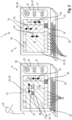
- FIG 2 shows a schematic representation of the operating and display unit 8 according to the invention, the left-hand representation showing the first navigation level 19, which will also be described in more detail, and the right-hand representation, the second navigation level 20, which will also be described in more detail, of the display 18 assigned to the operating and display unit 8.
- the operating and display unit 8 includes a first operating unit 22, which enables navigation within a menu level 19, 20, and at least one further operating unit 23, by means of which inputs can be made by the operator 24. It is within the scope of the invention that the first and second operating units 22, 23 can be combined in a single operating unit in a manner that is not shown.
- the display 18 embodied as a touchscreen monitor 21 has a display area 26 embodied as a so-called header menu bar 25 in its upper area, which is permanently visible at least in the first navigation level 19 .
- the header menu bar 25 includes the working phases 27 of the agricultural working machine 1, which are to be described in more detail below, with each of the working phases 27 being caused by horizontal scrolling of the header menu bar 25 by the operator 24 of the agricultural working machine 1 via the touchscreen function by horizontally dragging the header menu bar 25 is selectable.
- another display area 28, which is visible in all available navigation levels 19, 20, is assigned to it, which includes a "Favorites” display area 29 and a “Hotkey” display area 30, with the "Favorites " 29 permanently system-relevant information is visualized and in the display area "Hotkey” 30 information relevant to the navigation level can be visualized by activating the respective display area 29.
- the information relevant to the navigation level stored in the "Hotkey” button 30 can be activated either by touching this button on the display 18 designed as a touchscreen monitor 21 or by pressing the "Hotkey” button 31 arranged in the first operating unit 22 .
- the display 18 that can be operated according to the invention in navigation levels 19, 20 comprises, in a first navigation level 19, at least one “work phase” visualization area 32 and a “tool menu” visualization area 33, with the operator 24 of the agricultural working machine 1 being able to scroll horizontally 34 in the “work phase” visualization area. 32 and vertical scrolling 35 in the visualization area "tool menu” 33 in the respective visualization area 32, 33 can navigate. Since the display 18 is designed as a touchscreen monitor 21, the horizontal and vertical scrolling 34, 35 is effected by touching the display 18 and dragging the respective visualization area 32, 33 in the desired direction. So that the operator 24 is informed about the currently activated work phase 32 while scrolling in the "Work phase” 32 visualization area, another display field 36 is shown on the display 18, which shows all the selectable work phases 27, with the activated work phase 27a being visualized as highlighted.
- the display 18 comprises at least one "Tool Content” visualization area 37, the "Tool Menu” visualization area 33 and a "Tool Submenu” visualization area 38, wherein in each of these visualization areas 33, 37, 38 by vertical scrolling 35 can be navigated.
- the vertical scrolling 35 is achieved by touching the display 18 and dragging the respective visualization area 33, 37, 38 into the desired one direction effected.
- the second navigation level 20 it is possible to navigate between the visualization areas 33 , 37 , 38 and within each visualization area 33 , 37 , 38 using the operating elements 39 assigned to the first operating unit 22 .
- the first control unit 22 has a control element 39 designed as a rotary/push switch 40, when it is rotated it can be switched back and forth between the visualization areas 33, 37, 38 and it is possible to navigate within a visualization area 33, 37, 38 Press function of the rotary pushbutton switch 40 is used to confirm or select a selected function. Editing made with the rotary pushbutton switch 40 can be reset by means of the additional operating element 39 embodied as an escape key 41 .
- the display 18 can be operated in the described first and second navigation levels 19, 20, the display 18 being divided into visualization areas 32, 33, 37, 38 within a navigation level 19, 20 and at least part of the visualization areas 32, 33, 37, 38 can be moved relative to one another, a navigation option is created which enables the operator 24 of the agricultural working machine 1 to change machine parameters quickly and in a clear manner.
- Orientation within the available navigation levels 19, 20 is also increased by the fact that horizontal scrolling 34 is only possible in a first navigation level 19, while only vertical scrolling 35 is possible in the at least one further navigation level 20.
- the main effect of this is that the operator 24 of the agricultural working machine already recognizes from the movement of the visualization areas 32, 33, 37, 38 in which navigation level 19, 20 it is currently being navigated.
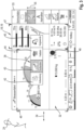
- FIG 3 shows a detailed view of the display 18 in the first navigation level 19.
- the display field 36 visualizing the available work phases includes the work phases “preparation” 42, "road travel” 43, “field travel” 44 and “headland” 45.
- the visualization area of each work phase is 42-45 structured in such a way that it comprises a "work phase content” visualization area 46 and at least one "tool view” visualization area 47 .
- the operator 24 by touching the display 48 18 with the finger or select the desired work phase 42-45 from a suitable object by either scrolling the “work phase” visualization area 32 in the horizontal direction 34 or by typing on the desired work phases 42-45 directly in the additional display field 36. Irrespective of this, the operator 24 can navigate in the first navigation level 19 in the “tool menu” 33 visualization area by vertical scrolling 35 in a manner yet to be described in more detail.
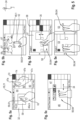
- figure 4 shows the example of an agricultural working machine 1 designed as a self-propelled forage harvester 49 changing the structure of the display 18 in the first navigation level 19.
- the change in the display structure is described below using the first navigation level 19, it is within the scope of the invention that the procedure to be described can also be used in an analogous manner to change the display structure in the second navigation level 20, so that a description of this procedure is omitted for reasons of simplification.
- the operator 24 of the forage harvester 49 has selected the “field travel” 44 work phase.
- Each of the visualization areas “work phase content” 46 and “tool view” 47 are subdivided into subareas 46a-b, 47ac, with the information visualized in the subareas 46a-b, 47a-c being interchangeable in subareas.
- the editing takes place in such a way that the operator 24 first selects a tool 50, here the tool "field navigation”, by touching 48 from the visualization area “tool menu” 33 and in one of the partial areas 46a-b, 47a-c of the visualization areas "Work Phase Content” 46 or “Tool View” 47 draws.
- the “field navigation” tool 50 is dragged into the lowermost subarea 47c of the “tool view” visualization area 47, with the activation of the subarea 47c being signaled by a border 51 highlighted in color. If the operator 24 interrupts the touch in this subarea 47c, a pop-up window 53 slides into the display from right to left in the horizontal direction 52 opens, which in the present case includes two alternative editing options 54, 55 for the "field navigation" tool 50. Because the operator 24 selects one of the alternative editing options 54, 55 from the pop-up window 53 that completely covers the visualization area "Tool View” 47 by touching 48, this editing option 55 initially becomes their symbol Selection optically highlighted, in the simplest case again by colored highlighting of the edge 51.
- the pop-up window 53 is closed again by moving 52 horizontally out of the display 18 and at the same time the selected editing option 55 has filled out the previously selected lowermost partial area 47c of the "Tool View” 47 visualization area.
- the selectable editing options 54, 55 are not limited to visual aspects but can also include various functions. At the same time, more than the 2 editing options 54, 55 described can be available, in which case navigating between the selectable editing options 54, 55 by vertical scrolling 35 in the opened pop-up window 53 becomes possible.
- a change from the first navigation level 19 to the further navigation level 20 is brought about after a desired work phase has been selected by the operator 24 touching one of the “work phase content” 46 or “tool view” 47 visualization areas. If the touch 48 takes place in the area of one of the icons 57 visualized on the display 18, the function or application linked to the touched icon 57 opens immediately. If an area between the icons 57 is touched, only the change between the navigation levels 19, 20 takes place, without this immediately leading to a change in the display structure.
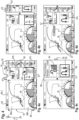
- FIG. 1 now shows the actuation scenarios according to the invention and to be explained in more detail for a display 18 designed as a touchscreen monitor 21.
- the display 18 is divided into different visualization areas 32, 33, 37, 38, 46, 47 within each navigation level 19, 20 , each visualization area 32, 33, 37, 38, 46, 47 being able to be assigned a large number of visualization contents 58.
- a visualization area 46, 47 according to Figure 5a is subdivided into display areas 60 which, in the simplest case, are connected to the partial areas 46a, b; 47a-c of the visualization areas “work phase content” 46 and “tool view” 47 correspond, the touchscreen functions 59 according to the invention can also be used independently of one another in these display areas 60.
- the touchscreen function 59 is configured as a zoom function 61, with each of the display areas 60 or each visualization area 32, 33, 37, 38, 46, 47 being independent of the other display or visualization areas 32, 33, 37, 38, 46, 47, 60 can be zoomed by the operator 24 using two-finger operation.
- the respective image section can be enlarged or reduced by moving the fingers 62 towards or away from one another, preferably the thumb and forefinger.
- the touchscreen monitor 21 can also be designed in such a way that, according to the representations c.) and d.).
- figure 5 a dragging touch 64 of the display 18 in the horizontal or vertical direction results in an increase in the speed of the vertical or horizontal scrolling 34,35.
- horizontal and vertical scrolling 64 can also be used as in figure 2 shown using the example of vertical scrolling 35 in the visualization areas 37, 38, 33 of the second navigation level 20, independently of one another in the most diverse visualization and display areas 32, 33, 37, 38, 46, 47, 60.
- Figure 5e can do the two-finger horizontal drag 64 in cases where one or more pop-up windows 53 are open, the pop-up window 53 touched in this way closes automatically.
- the agricultural working machine 1 that can be controlled by means of the operating and display unit 8 is not limited to an agricultural working machine 1 designed as a combine harvester 2 or forage harvester 49, but can be designed as desired, for example as a tractor-mounted implement combination .
- the parameters 64 that can be set with the operating and display unit 8 can be of any type and include, for example, machine parameters, quality parameters of the agricultural working machine, quality parameters of the harvested crop and harvested crop parameters.
Landscapes
- Engineering & Computer Science (AREA)
- General Engineering & Computer Science (AREA)
- Theoretical Computer Science (AREA)
- Human Computer Interaction (AREA)
- Physics & Mathematics (AREA)
- General Physics & Mathematics (AREA)
- Life Sciences & Earth Sciences (AREA)
- Environmental Sciences (AREA)
- User Interface Of Digital Computer (AREA)
- Management, Administration, Business Operations System, And Electronic Commerce (AREA)
- Navigation (AREA)
- Harvester Elements (AREA)
- Controls And Circuits For Display Device (AREA)
- Position Input By Displaying (AREA)
Applications Claiming Priority (2)
| Application Number | Priority Date | Filing Date | Title |
|---|---|---|---|
| DE102012107552.2A DE102012107552A1 (de) | 2012-08-17 | 2012-08-17 | Anzeigevorrichtung für Landmaschinen |
| EP13168250.2A EP2698701A3 (fr) | 2012-08-17 | 2013-05-17 | Dispositif d'affichage pour machines agricoles |
Related Parent Applications (1)
| Application Number | Title | Priority Date | Filing Date |
|---|---|---|---|
| EP13168250.2A Division EP2698701A3 (fr) | 2012-08-17 | 2013-05-17 | Dispositif d'affichage pour machines agricoles |
Publications (3)
| Publication Number | Publication Date |
|---|---|
| EP4231128A2 true EP4231128A2 (fr) | 2023-08-23 |
| EP4231128A3 EP4231128A3 (fr) | 2023-11-01 |
| EP4231128B1 EP4231128B1 (fr) | 2025-08-20 |
Family
ID=48482924
Family Applications (2)
| Application Number | Title | Priority Date | Filing Date |
|---|---|---|---|
| EP13168250.2A Ceased EP2698701A3 (fr) | 2012-08-17 | 2013-05-17 | Dispositif d'affichage pour machines agricoles |
| EP23178717.7A Active EP4231128B1 (fr) | 2012-08-17 | 2013-05-17 | Dispositif d'affichage pour machines agricoles |
Family Applications Before (1)
| Application Number | Title | Priority Date | Filing Date |
|---|---|---|---|
| EP13168250.2A Ceased EP2698701A3 (fr) | 2012-08-17 | 2013-05-17 | Dispositif d'affichage pour machines agricoles |
Country Status (6)
| Country | Link |
|---|---|
| US (1) | US9798451B2 (fr) |
| EP (2) | EP2698701A3 (fr) |
| CN (1) | CN103593135B (fr) |
| AR (1) | AR092163A1 (fr) |
| DE (1) | DE102012107552A1 (fr) |
| RU (1) | RU2631140C2 (fr) |
Families Citing this family (15)
| Publication number | Priority date | Publication date | Assignee | Title |
|---|---|---|---|---|
| US10318138B2 (en) * | 2011-03-11 | 2019-06-11 | Intelligent Agricultural Solutions Llc | Harvesting machine capable of automatic adjustment |
| US10321624B2 (en) | 2011-03-11 | 2019-06-18 | Intelligent Agriculture Solutions LLC | Air seeder manifold system |
| US20160062966A1 (en) * | 2014-08-26 | 2016-03-03 | Microsoft Corporation | Full screen pop-out of objects in editable form |
| AU2015314684B2 (en) | 2014-09-12 | 2020-09-03 | Precision Planting, Llc | Non-image-based grain quality sensor |
| USD789955S1 (en) * | 2014-11-04 | 2017-06-20 | Teenage Engineering Ab | Display screen or portion thereof with graphical user interface |
| US10058031B1 (en) | 2015-02-28 | 2018-08-28 | Hydro-Gear Limited Partnership | Lawn tractor with electronic drive and control system |
| US20170115843A1 (en) * | 2015-10-27 | 2017-04-27 | Cnh Industrial America Llc | Left hand area display for an agricultural system |
| DE102016007699A1 (de) * | 2016-06-23 | 2017-12-28 | Man Truck & Bus Ag | Bedienvorrichtung eines Kraftfahrzeugs |
| JP7274812B2 (ja) * | 2017-06-26 | 2023-05-17 | 株式会社クボタ | 作業機に備えられる表示装置 |
| US11042280B2 (en) * | 2018-03-05 | 2021-06-22 | Agco Corporation | Harvesting machine with visualization system |
| US10926768B1 (en) | 2018-06-18 | 2021-02-23 | Hydro-Gear Limited Partnership | Vehicle drive and control system |
| USD983219S1 (en) * | 2019-12-11 | 2023-04-11 | Prinoth S.P.A. | Display screen or a portion thereof with a graphical user interface |
| DE102020130449A1 (de) * | 2020-11-18 | 2022-05-19 | Claas E-Systems Gmbh | System zur Anzeige von Anzeigeobjekten |
| USD1054432S1 (en) * | 2022-01-04 | 2024-12-17 | Deere & Company | Display screen with a graphical user interface |
| USD1082806S1 (en) * | 2022-10-06 | 2025-07-08 | Tartan Aerial Sense Tech Private Limited | Display screen with transitional graphical user interface |
Citations (2)
| Publication number | Priority date | Publication date | Assignee | Title |
|---|---|---|---|---|
| DE10203370A1 (de) | 2002-01-29 | 2003-07-31 | Siemens Ag | Verfahren zur Steuerung einer fensterorientierten Bedienoberfläche und ein HMI Gerät zur Durchführung des Verfahrens |
| EP1650715A1 (fr) | 2004-09-30 | 2006-04-26 | CLAAS Selbstfahrende Erntemaschinen GmbH | Fenêtre de function échelonnable dans une unité d'affichage |
Family Cites Families (17)
| Publication number | Priority date | Publication date | Assignee | Title |
|---|---|---|---|---|
| US7469381B2 (en) * | 2007-01-07 | 2008-12-23 | Apple Inc. | List scrolling and document translation, scaling, and rotation on a touch-screen display |
| CA2559726C (fr) * | 2004-03-24 | 2015-10-20 | A9.Com, Inc. | Procede et systeme pour afficher des images dans un repertoire en ligne |
| US20060174212A1 (en) * | 2005-02-01 | 2006-08-03 | Eastman Kodak Company | Information presentation on wide-screen displays |
| US8078367B2 (en) * | 2007-01-08 | 2011-12-13 | Precision Planting, Inc. | Planter monitor system and method |
| US7697054B2 (en) * | 2007-03-29 | 2010-04-13 | Hewlett-Packard Development Company, L.P. | Image Manipulator for a camera |
| US7956869B1 (en) * | 2007-07-13 | 2011-06-07 | Adobe Systems Incorporated | Proximity based transparency of windows aiding in obscured window selection |
| US11126321B2 (en) * | 2007-09-04 | 2021-09-21 | Apple Inc. | Application menu user interface |
| CN101809531A (zh) * | 2007-10-02 | 2010-08-18 | 株式会社爱可信 | 终端装置、链接选择方法以及显示程序 |
| US8245155B2 (en) * | 2007-11-29 | 2012-08-14 | Sony Corporation | Computer implemented display, graphical user interface, design and method including scrolling features |
| KR101387527B1 (ko) * | 2007-12-06 | 2014-04-23 | 엘지전자 주식회사 | 단말기 및 그 메뉴 아이콘 디스플레이 방법 |
| US20100162181A1 (en) * | 2008-12-22 | 2010-06-24 | Palm, Inc. | Interpreting Gesture Input Including Introduction Or Removal Of A Point Of Contact While A Gesture Is In Progress |
| KR101640460B1 (ko) * | 2009-03-25 | 2016-07-18 | 삼성전자 주식회사 | 휴대 단말기의 분할 화면 운용 방법 및 이를 지원하는 휴대 단말기 |
| US9465532B2 (en) * | 2009-12-18 | 2016-10-11 | Synaptics Incorporated | Method and apparatus for operating in pointing and enhanced gesturing modes |
| US20110252357A1 (en) * | 2010-04-07 | 2011-10-13 | Imran Chaudhri | Device, Method, and Graphical User Interface for Managing Concurrently Open Software Applications |
| JP5617375B2 (ja) * | 2010-06-22 | 2014-11-05 | ソニー株式会社 | 画像表示装置、表示制御方法及びプログラム |
| KR101229699B1 (ko) * | 2011-05-12 | 2013-02-05 | 주식회사 케이티 | 애플리케이션 간의 콘텐츠 이동 방법 및 이를 실행하는 장치 |
| US20120289290A1 (en) * | 2011-05-12 | 2012-11-15 | KT Corporation, KT TECH INC. | Transferring objects between application windows displayed on mobile terminal |
-
2012
- 2012-08-17 DE DE102012107552.2A patent/DE102012107552A1/de not_active Ceased
-
2013
- 2013-05-17 EP EP13168250.2A patent/EP2698701A3/fr not_active Ceased
- 2013-05-17 EP EP23178717.7A patent/EP4231128B1/fr active Active
- 2013-08-08 US US13/962,258 patent/US9798451B2/en active Active
- 2013-08-15 RU RU2013138114A patent/RU2631140C2/ru active
- 2013-08-15 CN CN201310356060.2A patent/CN103593135B/zh active Active
- 2013-08-16 AR ARP130102925A patent/AR092163A1/es active IP Right Grant
Patent Citations (2)
| Publication number | Priority date | Publication date | Assignee | Title |
|---|---|---|---|---|
| DE10203370A1 (de) | 2002-01-29 | 2003-07-31 | Siemens Ag | Verfahren zur Steuerung einer fensterorientierten Bedienoberfläche und ein HMI Gerät zur Durchführung des Verfahrens |
| EP1650715A1 (fr) | 2004-09-30 | 2006-04-26 | CLAAS Selbstfahrende Erntemaschinen GmbH | Fenêtre de function échelonnable dans une unité d'affichage |
Also Published As
| Publication number | Publication date |
|---|---|
| EP4231128B1 (fr) | 2025-08-20 |
| DE102012107552A1 (de) | 2014-05-15 |
| CN103593135B (zh) | 2018-06-29 |
| AR092163A1 (es) | 2015-03-25 |
| EP4231128A3 (fr) | 2023-11-01 |
| US9798451B2 (en) | 2017-10-24 |
| CN103593135A (zh) | 2014-02-19 |
| RU2013138114A (ru) | 2015-02-20 |
| EP2698701A2 (fr) | 2014-02-19 |
| US20140053093A1 (en) | 2014-02-20 |
| EP2698701A3 (fr) | 2017-09-06 |
| RU2631140C2 (ru) | 2017-09-19 |
Similar Documents
| Publication | Publication Date | Title |
|---|---|---|
| EP2698054B1 (fr) | Dispositif d'affichage pour machines agricoles | |
| EP4231128B1 (fr) | Dispositif d'affichage pour machines agricoles | |
| EP4120056A1 (fr) | Dispositif d'affichage pour machines agricoles | |
| DE102008000001B4 (de) | Integrierte Hardware- und Softwarebenutzerschnittstelle | |
| DE69129265T2 (de) | Bildverschiebungssteuerung und Verfahren | |
| EP3378298A1 (fr) | Terminal agricole | |
| DE69937270T2 (de) | Multifunktioneller Joystick zur Kontrolle eines landwirtschaftlichen Fahrzeuges | |
| DE102020213211A1 (de) | System und Verfahren zur Rekonfiguration von Bedienersteuerungen | |
| EP1374027B1 (fr) | Positionnement de secteurs affiches sur une interface utilisateur | |
| EP2509470A1 (fr) | Appareil de cuisine | |
| DE102010048745A1 (de) | Benutzerschnittstelle und Verfahren zum Bedienen einer Benutzerschnittstelle | |
| EP3501255B1 (fr) | Machine de travail agricole destiné à traiter un processus de travail agricole | |
| DE102012220062A1 (de) | Einstellung mehrerer benutzereingabeparameter | |
| DE102014210893A1 (de) | Verfahren zum Betrieb einer Bildaufnahmeeinrichtung mit Touchscreen und Bildaufnahmeeinrichtung | |
| DE102013219194B4 (de) | Medizinsystem | |
| WO2010015303A1 (fr) | Procédé pour agrandir une zone de représentation sur un dispositif de représentation | |
| DE29516666U1 (de) | Bedieneinheit mit Bedienpult und elektronischer Anzeigeeinheit zum Steuern von Arbeitsgeräten an Nutzfahrzeugen | |
| DE102007026120B4 (de) | Verfahren zur selbsttätigen Steuerung eines Zeigerelements in graphischen Nutzerschnittstellen eines digitalen Bildinformationssystems | |
| EP3489067B1 (fr) | Système de fonctionnement pour un engin agricole | |
| DE10246629B4 (de) | Anordnung zur Menüsteuerung einer Set Top Box | |
| DE102013007495A1 (de) | Lebensmittelverarbeitungsvorrichtung mit einer Anzeige mit adaptivem Übersichtsfeld und Bedienfeld | |
| DE102016004630A1 (de) | Werkzeugmaschine sowie Verwendung eines berührempfindlichen Displays zur Ansteuerung eines Maschinenteils einer Werkzeugmaschine | |
| EP4006427A1 (fr) | Appareil électroménager doté d'une unité de commande et procédé d'affichage du contenu des sources de données externes | |
| WO2002087228A1 (fr) | Dispositif d'utilisation d'appareils de television | |
| EP3850637A1 (fr) | Dispositif d'affichage d'un dispositif de traitement médical |
Legal Events
| Date | Code | Title | Description |
|---|---|---|---|
| PUAI | Public reference made under article 153(3) epc to a published international application that has entered the european phase |
Free format text: ORIGINAL CODE: 0009012 |
|
| STAA | Information on the status of an ep patent application or granted ep patent |
Free format text: STATUS: THE APPLICATION HAS BEEN PUBLISHED |
|
| AC | Divisional application: reference to earlier application |
Ref document number: 2698701 Country of ref document: EP Kind code of ref document: P |
|
| AK | Designated contracting states |
Kind code of ref document: A2 Designated state(s): AL AT BE BG CH CY CZ DE DK EE ES FI FR GB GR HR HU IE IS IT LI LT LU LV MC MK MT NL NO PL PT RO RS SE SI SK SM TR |
|
| REG | Reference to a national code |
Ref country code: DE Ref legal event code: R079 Free format text: PREVIOUS MAIN CLASS: G06F0003048600 Ipc: G06F0003048830 Ref document number: 502013016606 Country of ref document: DE |
|
| P01 | Opt-out of the competence of the unified patent court (upc) registered |
Effective date: 20230823 |
|
| PUAL | Search report despatched |
Free format text: ORIGINAL CODE: 0009013 |
|
| AK | Designated contracting states |
Kind code of ref document: A3 Designated state(s): AL AT BE BG CH CY CZ DE DK EE ES FI FR GB GR HR HU IE IS IT LI LT LU LV MC MK MT NL NO PL PT RO RS SE SI SK SM TR |
|
| RIC1 | Information provided on ipc code assigned before grant |
Ipc: G06F 3/04817 20220101ALI20230922BHEP Ipc: G06F 3/0486 20130101ALI20230922BHEP Ipc: G06F 3/0485 20220101ALI20230922BHEP Ipc: G06F 3/0481 20220101ALI20230922BHEP Ipc: A01D 41/127 20060101ALI20230922BHEP Ipc: G06F 3/04886 20220101ALI20230922BHEP Ipc: G06F 3/04883 20220101AFI20230922BHEP |
|
| STAA | Information on the status of an ep patent application or granted ep patent |
Free format text: STATUS: REQUEST FOR EXAMINATION WAS MADE |
|
| 17P | Request for examination filed |
Effective date: 20240502 |
|
| RBV | Designated contracting states (corrected) |
Designated state(s): AL AT BE BG CH CY CZ DE DK EE ES FI FR GB GR HR HU IE IS IT LI LT LU LV MC MK MT NL NO PL PT RO RS SE SI SK SM TR |
|
| GRAP | Despatch of communication of intention to grant a patent |
Free format text: ORIGINAL CODE: EPIDOSNIGR1 |
|
| STAA | Information on the status of an ep patent application or granted ep patent |
Free format text: STATUS: GRANT OF PATENT IS INTENDED |
|
| INTG | Intention to grant announced |
Effective date: 20250331 |
|
| GRAS | Grant fee paid |
Free format text: ORIGINAL CODE: EPIDOSNIGR3 |
|
| GRAA | (expected) grant |
Free format text: ORIGINAL CODE: 0009210 |
|
| STAA | Information on the status of an ep patent application or granted ep patent |
Free format text: STATUS: THE PATENT HAS BEEN GRANTED |
|
| AC | Divisional application: reference to earlier application |
Ref document number: 2698701 Country of ref document: EP Kind code of ref document: P |
|
| AK | Designated contracting states |
Kind code of ref document: B1 Designated state(s): AL AT BE BG CH CY CZ DE DK EE ES FI FR GB GR HR HU IE IS IT LI LT LU LV MC MK MT NL NO PL PT RO RS SE SI SK SM TR |
|
| REG | Reference to a national code |
Ref country code: GB Ref legal event code: FG4D Free format text: NOT ENGLISH |
|
| REG | Reference to a national code |
Ref country code: CH Ref legal event code: EP |
|
| REG | Reference to a national code |
Ref country code: DE Ref legal event code: R096 Ref document number: 502013016606 Country of ref document: DE |
|
| REG | Reference to a national code |
Ref country code: IE Ref legal event code: FG4D Free format text: LANGUAGE OF EP DOCUMENT: GERMAN |
|
| REG | Reference to a national code |
Ref country code: NL Ref legal event code: MP Effective date: 20250820 |
|
| PG25 | Lapsed in a contracting state [announced via postgrant information from national office to epo] |
Ref country code: IS Free format text: LAPSE BECAUSE OF FAILURE TO SUBMIT A TRANSLATION OF THE DESCRIPTION OR TO PAY THE FEE WITHIN THE PRESCRIBED TIME-LIMIT Effective date: 20251220 |
|
| PG25 | Lapsed in a contracting state [announced via postgrant information from national office to epo] |
Ref country code: NO Free format text: LAPSE BECAUSE OF FAILURE TO SUBMIT A TRANSLATION OF THE DESCRIPTION OR TO PAY THE FEE WITHIN THE PRESCRIBED TIME-LIMIT Effective date: 20251120 |
|
| REG | Reference to a national code |
Ref country code: LT Ref legal event code: MG9D |
|
| PG25 | Lapsed in a contracting state [announced via postgrant information from national office to epo] |
Ref country code: PT Free format text: LAPSE BECAUSE OF FAILURE TO SUBMIT A TRANSLATION OF THE DESCRIPTION OR TO PAY THE FEE WITHIN THE PRESCRIBED TIME-LIMIT Effective date: 20251222 |
|
| PG25 | Lapsed in a contracting state [announced via postgrant information from national office to epo] |
Ref country code: FI Free format text: LAPSE BECAUSE OF FAILURE TO SUBMIT A TRANSLATION OF THE DESCRIPTION OR TO PAY THE FEE WITHIN THE PRESCRIBED TIME-LIMIT Effective date: 20250820 |
|
| PG25 | Lapsed in a contracting state [announced via postgrant information from national office to epo] |
Ref country code: NL Free format text: LAPSE BECAUSE OF FAILURE TO SUBMIT A TRANSLATION OF THE DESCRIPTION OR TO PAY THE FEE WITHIN THE PRESCRIBED TIME-LIMIT Effective date: 20250820 Ref country code: HR Free format text: LAPSE BECAUSE OF FAILURE TO SUBMIT A TRANSLATION OF THE DESCRIPTION OR TO PAY THE FEE WITHIN THE PRESCRIBED TIME-LIMIT Effective date: 20250820 |
|
| PG25 | Lapsed in a contracting state [announced via postgrant information from national office to epo] |
Ref country code: GR Free format text: LAPSE BECAUSE OF FAILURE TO SUBMIT A TRANSLATION OF THE DESCRIPTION OR TO PAY THE FEE WITHIN THE PRESCRIBED TIME-LIMIT Effective date: 20251121 |
|
| PG25 | Lapsed in a contracting state [announced via postgrant information from national office to epo] |
Ref country code: SE Free format text: LAPSE BECAUSE OF FAILURE TO SUBMIT A TRANSLATION OF THE DESCRIPTION OR TO PAY THE FEE WITHIN THE PRESCRIBED TIME-LIMIT Effective date: 20250820 |
|
| PG25 | Lapsed in a contracting state [announced via postgrant information from national office to epo] |
Ref country code: LV Free format text: LAPSE BECAUSE OF FAILURE TO SUBMIT A TRANSLATION OF THE DESCRIPTION OR TO PAY THE FEE WITHIN THE PRESCRIBED TIME-LIMIT Effective date: 20250820 |
|
| PG25 | Lapsed in a contracting state [announced via postgrant information from national office to epo] |
Ref country code: PL Free format text: LAPSE BECAUSE OF FAILURE TO SUBMIT A TRANSLATION OF THE DESCRIPTION OR TO PAY THE FEE WITHIN THE PRESCRIBED TIME-LIMIT Effective date: 20250820 Ref country code: BG Free format text: LAPSE BECAUSE OF FAILURE TO SUBMIT A TRANSLATION OF THE DESCRIPTION OR TO PAY THE FEE WITHIN THE PRESCRIBED TIME-LIMIT Effective date: 20250820 |
|
| PG25 | Lapsed in a contracting state [announced via postgrant information from national office to epo] |
Ref country code: RS Free format text: LAPSE BECAUSE OF FAILURE TO SUBMIT A TRANSLATION OF THE DESCRIPTION OR TO PAY THE FEE WITHIN THE PRESCRIBED TIME-LIMIT Effective date: 20251120 |
|
| PG25 | Lapsed in a contracting state [announced via postgrant information from national office to epo] |
Ref country code: ES Free format text: LAPSE BECAUSE OF FAILURE TO SUBMIT A TRANSLATION OF THE DESCRIPTION OR TO PAY THE FEE WITHIN THE PRESCRIBED TIME-LIMIT Effective date: 20250820 |
|
| PG25 | Lapsed in a contracting state [announced via postgrant information from national office to epo] |
Ref country code: SM Free format text: LAPSE BECAUSE OF FAILURE TO SUBMIT A TRANSLATION OF THE DESCRIPTION OR TO PAY THE FEE WITHIN THE PRESCRIBED TIME-LIMIT Effective date: 20250820 |
|
| PG25 | Lapsed in a contracting state [announced via postgrant information from national office to epo] |
Ref country code: DK Free format text: LAPSE BECAUSE OF FAILURE TO SUBMIT A TRANSLATION OF THE DESCRIPTION OR TO PAY THE FEE WITHIN THE PRESCRIBED TIME-LIMIT Effective date: 20250820 |
|
| PG25 | Lapsed in a contracting state [announced via postgrant information from national office to epo] |
Ref country code: CZ Free format text: LAPSE BECAUSE OF FAILURE TO SUBMIT A TRANSLATION OF THE DESCRIPTION OR TO PAY THE FEE WITHIN THE PRESCRIBED TIME-LIMIT Effective date: 20250820 |
|
| PG25 | Lapsed in a contracting state [announced via postgrant information from national office to epo] |
Ref country code: SK Free format text: LAPSE BECAUSE OF FAILURE TO SUBMIT A TRANSLATION OF THE DESCRIPTION OR TO PAY THE FEE WITHIN THE PRESCRIBED TIME-LIMIT Effective date: 20250820 Ref country code: EE Free format text: LAPSE BECAUSE OF FAILURE TO SUBMIT A TRANSLATION OF THE DESCRIPTION OR TO PAY THE FEE WITHIN THE PRESCRIBED TIME-LIMIT Effective date: 20250820 |