EP4231134A1 - Verfahren und system zur berechnung von punktprodukten - Google Patents
Verfahren und system zur berechnung von punktprodukten Download PDFInfo
- Publication number
- EP4231134A1 EP4231134A1 EP23155921.2A EP23155921A EP4231134A1 EP 4231134 A1 EP4231134 A1 EP 4231134A1 EP 23155921 A EP23155921 A EP 23155921A EP 4231134 A1 EP4231134 A1 EP 4231134A1
- Authority
- EP
- European Patent Office
- Prior art keywords
- numbers
- bits
- floating
- product
- exponent
- Prior art date
- Legal status (The legal status is an assumption and is not a legal conclusion. Google has not performed a legal analysis and makes no representation as to the accuracy of the status listed.)
- Pending
Links
Images



Classifications
-
- G—PHYSICS
- G06—COMPUTING OR CALCULATING; COUNTING
- G06F—ELECTRIC DIGITAL DATA PROCESSING
- G06F7/00—Methods or arrangements for processing data by operating upon the order or content of the data handled
- G06F7/38—Methods or arrangements for performing computations using exclusively denominational number representation, e.g. using binary, ternary, decimal representation
- G06F7/48—Methods or arrangements for performing computations using exclusively denominational number representation, e.g. using binary, ternary, decimal representation using non-contact-making devices, e.g. tube, solid state device; using unspecified devices
- G06F7/544—Methods or arrangements for performing computations using exclusively denominational number representation, e.g. using binary, ternary, decimal representation using non-contact-making devices, e.g. tube, solid state device; using unspecified devices for evaluating functions by calculation
- G06F7/5443—Sum of products
-
- G—PHYSICS
- G06—COMPUTING OR CALCULATING; COUNTING
- G06F—ELECTRIC DIGITAL DATA PROCESSING
- G06F7/00—Methods or arrangements for processing data by operating upon the order or content of the data handled
- G06F7/38—Methods or arrangements for performing computations using exclusively denominational number representation, e.g. using binary, ternary, decimal representation
- G06F7/48—Methods or arrangements for performing computations using exclusively denominational number representation, e.g. using binary, ternary, decimal representation using non-contact-making devices, e.g. tube, solid state device; using unspecified devices
- G06F7/483—Computations with numbers represented by a non-linear combination of denominational numbers, e.g. rational numbers, logarithmic number system or floating-point numbers
- G06F7/487—Multiplying; Dividing
- G06F7/4876—Multiplying
-
- G—PHYSICS
- G06—COMPUTING OR CALCULATING; COUNTING
- G06F—ELECTRIC DIGITAL DATA PROCESSING
- G06F17/00—Digital computing or data processing equipment or methods, specially adapted for specific functions
- G06F17/10—Complex mathematical operations
- G06F17/16—Matrix or vector computation, e.g. matrix-matrix or matrix-vector multiplication, matrix factorization
-
- G—PHYSICS
- G06—COMPUTING OR CALCULATING; COUNTING
- G06F—ELECTRIC DIGITAL DATA PROCESSING
- G06F7/00—Methods or arrangements for processing data by operating upon the order or content of the data handled
- G06F7/38—Methods or arrangements for performing computations using exclusively denominational number representation, e.g. using binary, ternary, decimal representation
- G06F7/48—Methods or arrangements for performing computations using exclusively denominational number representation, e.g. using binary, ternary, decimal representation using non-contact-making devices, e.g. tube, solid state device; using unspecified devices
- G06F7/483—Computations with numbers represented by a non-linear combination of denominational numbers, e.g. rational numbers, logarithmic number system or floating-point numbers
Definitions
- number formats typically in binary notation or base 2, for performing various computations. These number formats include fixed-point or floating-point number formats. Fixed point number formats can provide additional precision but is used to represent only a limited range of values. Therefore, floating point number formats are used in most of the modern computing systems to provide a trade-off between range and precision.
- a floating-point number comprises a mantissa ( m ) having a bit length of 'b' bits, an exponent ( e ) having a bit length of 'a' bits and optionally a sign bit ( s ) to represent a binary number.
- the exponent is biased (i.e. offset) by a value ( c ) so as to represent numbers smaller than 1 and is used to encode exceptional values at its end points.
- the floating-point number x is said to be normalized and the number x is represented as (-1) s 2 e - c (1 + 2 - b m ).
- floating point numbers can be used to represent very small or very large numbers precisely using scientific notation, in binary or in some other base.
- the use of floating-point numbers in arithmetic computations provides varying degrees of precision depending on the bit length or type of floating-point format used.
- a dot product unit 100 using this principle is shown in FIG.1 .
- the dot product unit 100 comprises a set of floating point multiplication units 102a, 102b, 102c and 102d, and a set of floating point adder units 104a, 104b and 104c.
- the dot product unit 100 is implemented as a tree of floating point multiplication units and addition units.
- the dot product unit 100 receives a first set of floating point numbers (a 1 , a 2 , a 3 , and a 4 ) and a second set of floating point numbers (b 1 , b 2 , b 3 , and b 4 ) as inputs.
- a first set of floating point numbers a 1 , a 2 , a 3 , and a 4
- second set of floating point numbers b 1 , b 2 , b 3 , and b 4
- Each floating point number a i in the first set of floating-point numbers is provided as a first input to a respective one of floating point multiplication units 102a, 102b, 102c and 102d.
- Each floating point number b i in a second set of floating-point numbers is provided as a second input to a respective one of floating point multiplication units 102a, 102b, 102c and 102d.
- Each floating point multiplication unit 102a, 102b, 102c and 102d performs the multiplication of floating point numbers a i and b i , to obtain a product c i .
- the results are accumulated by a series of adders in any dynamically or statically chosen order to obtain the output.
- the adders can be arranged in any order.
- the product c 1 and c 2 from two consecutive floating point multiplication units 102a and 102b are provided to a first floating point adder unit 104a to add the products (c 1 and c 2 ).
- the products c 3 and c 4 from the next two consecutive floating point multiplication units 102c and 102d are provided to a second floating point adder unit 104b to add the product (c 3 and c 4 ).
- the accumulated values are further provided as an input to a third floating point adder 104c to be accumulated to obtain the output y.
- the output from the multiplier or adder in each step is rounded, which causes a rounding error in the output generated by each step.
- the rounding error is a characteristic feature of floating-point calculations.
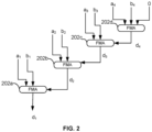
- a dot product unit 200 using this principle is shown in FIG. 2 .
- the dot product unit 200 comprises a set of Fused Multiply and Add (FMA) units 202a, 202b, 202c and 202d.
- FMA Fused Multiply and Add
- An FMA unit performs the floating point multiplication and addition in a single step with a single rounding.
- FMA improves the speed and accuracy of computation of dot product involving accumulation of products.
- the results of one fused multiply add unit is provided as an input to another fused multiply add unit such that the product of two numbers is added to the product of the next two numbers.
- the dot product unit 200 receives both sets of floating point numbers a i and b i as inputs.
- Each floating point number a i in the first set of floating-point numbers is provided as a first input to a respective one of FMA units 202a, 202b, 202c and 202d.
- Each floating point number b i in the second set of floating-point numbers is provided as a second input to a respective one of FMA units 202a, 202b, 202c and 202d.
- Each FMA 202a, 202b and 202c computes multiplication of numbers a i and b i and adds it with the results of a previous FMA with a single rounding (N.B.
- the FMA 202d receives the numbers a 4 and b 4 as the multiplicand inputs. Further a 0 input is provided as a third input. The FMA 202d multiplies a 4 and b 4 and adds the result with 0 to obtain the output d 4 . Further, the FMA 202c receives the numbers a 3 and b 3 as the multiplicand inputs and d 4 as a third input.
- the FMA 202c multiplies a 3 and b 3 and adds the result with d 4 to obtain the output d 3 .
- FMA 202b obtains the output d 3 by multiplying a 2 and b 2 and adding the result with d 3 .
- pairs of floating-point number a i and b i from both sets of floating point numbers are multiplied together and added to a previously calculated output to generate a new or cumulative output.
- the overall sum is performed as a sequence of multiplication and addition of numbers.
- a final output (y) generated after multiplying and adding all the floating-point numbers in the array is provided as the output.
- Either of the above described methods can be implemented iteratively looping through the same unit(s) or concurrently by using a parallel or sequential composition of units. Whether using the first dot product unit 100 or 200, the precision of the output cannot be guaranteed as different ordering of inputs may yield different results, due to the intermediate rounding operations. Further, there is a high delay introduced due to the number of logic gates in the critical path.
- a method of performing dot product of an array of ⁇ 2k' floating point numbers comprising two sets of k floating-point numbers a i and b i is disclosed.
- the method includes receiving both sets of 'k' floating point numbers and multiplying each floating point number a i with a floating point number b i to generate k product numbers (z i ), each product number (z i ) having a mantissa bit length of 'r+ log (k-1) +1' bits.
- the method further comprises creating a set of 'k' numbers (y i ) based on the k product numbers (z i ), the numbers (y i ) having a bit-length of 'n' bits.
- the method includes identifying a maximum exponent sum (e max ) among k exponent sums (eab i ) of each pair of floating point numbers a i and b i , aligning the magnitude bits of the numbers (y i ) based on the maximum exponent sum (e max ) and adding the set of 'k' numbers concurrently to obtain the dot product.
- each number in the first set of k floating-point numbers a 0 , a 1 ..., a k-1 comprises a mantissa (ma i ) and an exponent (ea i ) and each number in the second set of k floating-point numbers b 0 , b 1 ..., b k-1 comprises a mantissa (mb i ) and an exponent (eb i ), where each mantissa (ma i ) is having a bit length of ⁇ p' bits and each mantissa (mb i ) is having a bit length of 'q' bits.
- multiplying each floating point number a i with the corresponding floating point number b i comprises multiplying mantissa (ma i ) and mantissa (mb i ) to obtain an intermediate mantissa product (mab i ).
- generating k product numbers (z i ) having the mantissa bit length of 'r+ log (k-1) +1' bits comprises: rounding, the bits of the intermediate mantissa product (mab i ) to r+ log (k-1) +1 bits, if p+q+2>r+ log (k-1) +1 bits; or padding, extra least-significant bits to the bit length of the intermediate mantissa product (mab i ) to generate r+ log (k-1) +1 bits, if p+q+2 ⁇ r+ log (k-1) +1 bits.
- identifying a maximum exponent sum includes identifying the maximum value among k exponent sums (eab i ) where k exponent sums (eab i ) is obtained by summing exponent (ea i ) and exponent (eb i ).
- adding extra most-significant bits to the bit length 'r+ log (k-1) +1' of the product numbers (z i ) comprises adding at least ⁇ log 2 k ⁇ number of the most-significant bits.
- adding at least extra most-significant bits to the bit length of the product numbers (zi) further comprises adding one or more least-significant bits to the bit length of the product numbers (z i ).
- the method further comprises: calculating an output value by processing 'k' numbers (y i ); renormalizing the output value; and rounding the output value to represent the output value as a floating-point number.
- aligning the magnitude bits of the numbers (y i ) to be based on the maximum exponent (e max ) comprises the steps of, for each floating-point number (i): calculating the difference (e d ) between the maximum exponent sum (e max ) and each exponent sum (eab i ); and shifting the magnitude bits of the corresponding number (y i ), to the LSB side, based on the calculated difference (e d ).
- the method further comprises performing rounding or truncating the bits of the numbers that are shifted outside the bit-length of the number.
- the method further comprises determining a two's complement of the magnitude bits of the numbers, based on a sign bit (s i ) of each corresponding number, if the set of 'k' floating point numbers comprises signed floating-point numbers.
- a hardware implementation for performing dot product of an array of ⁇ 2k' floating point numbers, k ⁇ 3, the array comprising a first set of k floating-point numbers a 0 , a 1 ..., a k-1 , and a second set of k floating-point numbers b 0 , b 1 ...,b k-1 , wherein the hardware implementation comprises: a multiplication unit, a format conversion unit, a maximum exponent detection unit, an alignment unit and a processing unit.
- the multiplication unit comprising a plurality of multiplier configured to: receive both sets of 'k' floating point numbers; multiply each floating point number a i with a floating point number b i to generate k product numbers (z i ), each product number (z i ) having a mantissa bit length of 'r+ log (k-1) +1' bits.
- the format conversion unit configured to create a set of 'k' numbers (y i ) based on the k product numbers (z i ), the numbers (y i ) having a bit-length of 'n' bits obtained by adding at least extra most-significant bits to the bit length of the product numbers (z i ), wherein the 'n' bits comprises a number of magnitude bits, wherein 'n' is r + ⁇ log 2 k ⁇ + ⁇ log 2 k ⁇ 1 ⁇ + x bits, where x is an integer, and x ⁇ 2.
- the maximum exponent detection unit configured to identify a maximum exponent sum (e max ) among k exponent sums (eab i ), each exponent sum is the sum of exponents of the floating point number a i and the floating point number b i .
- the alignment unit configured to align the magnitude bits of the numbers based on the maximum exponent sum (e max ).
- the processing unit configured to add the set of 'k' numbers concurrently to generate an output value.
- the hardware implementation further comprises a renormalizing unit configured to: renormalize the output value; and round the output value to represent the output value as a floating-point number.
- a renormalizing unit configured to: renormalize the output value; and round the output value to represent the output value as a floating-point number.
- each number in the first set of k floating-point numbers a 0 , a 1 ..., a k-1 comprises a mantissa (ma i ) and an exponent (ea i ) and each number in the second set of k floating-point numbers b 0 , b 1 ..., b k-1 comprises a mantissa (mb j ) and an exponent (eb i ), where each mantissa (ma i ) is having a bit length of ⁇ p' bits and each mantissa (mb i ) is having a bit length of 'q' bits.
- the multiplication unit comprises a plurality of multiplier units configured to multiply concurrently each mantissa (ma i ) with corresponding mantissa (mb i ) to obtain an intermediate mantissa product (mab i ).
- the multiplication unit is configured to generate k product number (z i ) having the mantissa bit length of 'r+ log (k-1) +1' bits by: rounding, the bits of the intermediate mantissa product (mab i ) to r+ log (k-1) +1 bits, if p+q+2>r+ log (k-1) +1 bits; or padding, extra least-significant bits to the bit length of the intermediate mantissa product (mab i ) to generate r+ log (k-1) +1 bits, if p+q+2 ⁇ r+ log (k-1) +1 bits.
- the maximum exponent detection unit is configured to identify a maximum exponent sum (e max ) among k exponent sums (eab i ), where k exponent sums (eab i ) is obtained by summing exponent (ea i ) and exponent (eb i ).
- the alignment unit is configured to align the magnitude bits of the numbers to be based on the maximum exponent (e max ), wherein the alignment unit comprises: a plurality of subtraction units, wherein each subtraction unit is configured to calculate the difference (e d ) between the maximum exponent sum (e max ) and exponent sum (eab i ); and a plurality of shifter units, each shifter unit configured to shift the magnitude bits of the corresponding number, to the LSB side, based on the calculated difference (e d ).
- the alignment unit is configured to further truncate the bits of the numbers that are shifted outside of the bit length of the numbers.
- the alignment unit further comprises a plurality of complementing units configured to determine two's complement of the magnitude bits of each number, based on a sign bit (s i ) of the corresponding number, if the set of 'k' floating point numbers comprises signed floating point numbers.
- a hardware implementation for performing dot product of an array of ⁇ 2k' floating point numbers, k ⁇ 3, the array comprising a first set of k floating-point numbers a 0 , a 1 ..., a k-1 , and a second set of k floating-point numbers b 0 , b 1 ..., b k-1 , wherein the hardware implementation comprises a multiplication unit, a format conversion unit, a maximum exponent detection unit, an alignment unit and a processing unit.
- the multiplication unit comprising a plurality of multiplier configured to: receive both sets of 'k' floating point numbers; multiply each floating point number a i with a floating point number b i , each multiplication generating a first intermediate product number (z i ') and a second intermediate product numbers (z i "), thereby generating 2k product numbers comprising k first intermediate product numbers (z i ') and k second intermediate product numbers (z i "), each having a bit length of 'r+ log (k-1) +2' bits.
- the format conversion unit configured to: create a set of ⁇ 2k' numbers comprising k first numbers (y i ') and k second numbers (y i "), based on the 2k product numbers, each having a bit-length of 'n' bits obtained by adding extra most-significant bits to the bit length of the product numbers (z i and z i "), wherein the 'n' bits comprises a number of magnitude bits, wherein 'n' is r + 1 + ⁇ log 2 k ⁇ + ⁇ log 2 k ⁇ 1 ⁇ + x bits, where x is an integer, and x ⁇ 1.
- the maximum exponent detection unit configured to identify a maximum exponent sum (e max ) among k exponent sums (eab i ), each exponent sum is the sum of exponents of the floating point number a i and the floating point number b i .
- the alignment unit configured to align the magnitude bits of the numbers (y i ' and y i ") based on the maximum exponent sum (e max ).
- the processing unit configured to add the set of ⁇ 2k' numbers concurrently to generate an output value.
- the hardware implementation hardware implementation for performing dot product according to the first aspect discussed above may be embodied in hardware on an integrated circuit.
- a method of manufacturing at an integrated circuit manufacturing system, a hardware implementation for performing dot product.
- an integrated circuit definition dataset that, when processed in an integrated circuit manufacturing system, configures the system to manufacture a hardware implementation for performing dot product.
- a non-transitory computer readable storage medium having stored thereon a computer readable description of a hardware implementation for performing dot product that, when processed in an integrated circuit manufacturing system, causes the integrated circuit manufacturing system to manufacture an integrated circuit embodying a hardware implementation for performing dot product.
- an integrated circuit manufacturing system comprising: a non-transitory computer readable storage medium having stored thereon a computer readable description of the a hardware implementation for performing dot product according to the first aspect discussed above.; a layout processing system configured to process the computer readable description so as to generate a circuit layout description of an integrated circuit embodying the hardware implementation for performing dot product; and an integrated circuit generation system configured to manufacture the hardware implementation for performing dot product according to the circuit layout description.
- the conventional hardware for performing a dot product of two sets of numbers includes hardware implementing separate multiplication and addition units or one implementing fused multiplication and addition units.
- the multiplicands a i and b i from both sets of floating point numbers may be represented in an incoming format F comprising a mantissa and an exponent.
- the mantissa ma i and mb i each comprise a bit length of p bits when represented in the incoming format F.
- the output of the multiplication unit may have a floating point number format F'.
- the format F' need not be the same as format F, and may have a mantissa width large enough to hold the exact multiplication output - for example the mantissa product (c i ) may be twice as large as the mantissa bit length of the multiplicands a i and b i .
- the multiplicands a i and b i may be represented in different formats such that the mantissas of a i and b i may have different bit lengths.
- the multiplication output may have a floating point format F' where the mantissa product is the sum of the mantissa bitlength of a i and the mantissa bit length of b i .
- the dot product unit 100 using separate multiplication and addition described in FIG.1 has the same precision as the dot product unit 200 using fused multiplication and addition units, assuming no overflow or underflow, because there is no rounding required.
- the second format F' is not wide enough to hold the exact multiplication output then performing dot product using the dot product unit 200 implementing fused multiplication and addition unit is more precise.
- FIG. 1 shows a particular implementation of a network of floating point adders taking the outputs of the multiplication units 102a, 102b, 102c and 102d.
- the illustrated network of floating point adders in Fig. 1 is a balanced tree (or a balanced tree adder), for performing parallel summation and aimed at reducing latency.
- addition of 'n' floating-point numbers i.e. in Fig 1 , the multiplication outputs c i
- the tree adder need not be a balanced structure.
- the tree adder can instead add the floating-point numbers using a single adder at every different stage. For example, any two floating point numbers are added in a first stage to generate a first sum value. Further, the first sum value is added to another floating-point number in a second stage using a second adder to generate a second sum value and so on.
- the latency of the arrangement increases in this example compared to a balanced tree adder.
- the existing methods of processing floating point numbers such as performing dot product using separate multiplication and addition units as described in FIG.1 or using fused multiplication and addition units as described in FIG.2 generate output values of varying precision based on the order in which the numbers are provided as the input. That is, a certain order of providing the inputs generates the best result which is the closest approximation to the actual dot product of the numbers. Other orders of providing the inputs may generate results which are not so close to the actual dot product of the numbers. Thus, based on the order in which the inputs are provided, there could be a range of results obtained, around the actual dot product of the floating-point numbers.
- the method includes receiving the inputs in their incoming format, generating the output of the multiplication unit in a first (intermediate) format, and then converting the first format to a number in a second (intermediate) format for performing addition (the output of which may be in a further format that may or may not be the same as any of the previously mentioned formats). More precisely the method includes receiving a floating-point number from each set in an incoming format, generating a product number having a first format by performing mantissa multiplication and exponent summation concurrently while emulating the precision of a chosen conventional multiplier. Further, the method includes processing the numbers in the second format concurrently (e.g. obtaining a sum by performing a single sum over all the numbers in the set, in contrast to performing multiple sums across the set) to generate an output value.
- FIG. 3 is a block diagram illustrating an example of an implementation of an architecture for processing a set of k floating-point numbers.
- the architecture 300 is a dot product unit for performing multiplication and addition of a large array of 2k floating point numbers to generate an output value.
- the large array of 2k floating point numbers comprise a first set of k floating-point numbers (a 0 , a 1 , a 2 ... a k-1 ) and a second set of k floating-point numbers (b 0 , b 1 , b 2 ... b k-1 ).
- the architecture is particularly suitable for calculating the dot product of large arrays of numbers, but can be used to calculate the dot product of two, or more than two, numbers as required.
- the architecture 300 comprises a mantissa multiplication unit 301, a format conversion unit 302, an exponent addition unit 303, a maximum exponent detection unit 304, an alignment unit 306, a processing unit 308, and a re-normalizing unit 310.
- Each number in the first set of 'k' floating-point numbers comprises a mantissa ma i and an exponent ea i .
- Each number in the second set of 'k' floating-point numbers comprises a mantissa mb i and an exponent eb i .
- Each number in the first set of 'k' floating-point numbers is having a mantissa bit length of ⁇ p' bits and each number in the second set of 'k' floating-point numbers is having a mantissa bit length of 'q' bits.
- Both sets of 'k' floating-point numbers may be signed numbers or unsigned numbers. In the case of signed numbers, the numbers would also each comprise a sign bit (sa i or sb i ) as well as the mantissa and exponent. However, some floating-point formats (e.g. unsigned formats) may not include a sign bit.
- the first set of k floating-point numbers (a 0 , a 1 , a 2 ... a k-1 ) and the second set of k floating-point numbers (b 0 , b 1 , b 2 ... b k-1 ) can be received in an input unit (not shown in the figure).
- the input unit can be a storage or a memory unit that can store the received inputs.
- Both sets of 'k' floating-point numbers are stored in an incoming format. Both sets of 'k' floating-point numbers may be of the same format or of different incoming formats for example if p ⁇ q.
- the bit-length of the mantissa and exponent of the numbers in the incoming format is identified based on the type of the floating-point number format.
- the incoming format may be a predefined format that the architecture 300 is designed to receive, or may be identified on a task-by-task basis (e.g. by a controller, not shown).
- Examples of various types of the floating-point number formats include but are not limited to IEEE formats including half precision floating-point numbers (16 bit float), single precision floating-point numbers (float) and double precision floating-point numbers (double), or other formats such as a brain floating-point numbers (bfloat16).
- both the number a i in the first set and number b i in the second set to have the same incoming format as IEEE single precision floating-point format having a mantissa (ma i or mb i ) with a bit length of 23 bits and an exponent (ea i or eb i ) with a bit length of 8 bits.
- the informing formats of both the number a i in the first set and number b i in the second set may be different.
- IEEE single precision floating-point format as the incoming format of the number a i in the first set having a mantissa ma i with a bit length of 23 bits and an exponent ea i with a bit length of 8 bits
- brain floating-point format as the incoming format of the number b i in the first set having a mantissa mb i with a bit length of 7 bits and an exponent eb i with a bit length of 8 bits.
- the invention is not limited to these (combinations of) formats and a person skilled in the art would understand that the architecture 300 could be implemented to use numbers in any type of the floating-point number format to perform the method described herein.
- the mantissa ma i of each number in the first set of 'k' floating-point numbers and the mantissa mb i of each number in the second set of 'k' floating-point numbers stored in an incoming format is provided to a mantissa multiplication unit 301.
- the fractional part of the mantissa ma i having the bit length of ⁇ p' bits may be extended by the implicit leading bit to obtain a normalised mantissa of p+1 bits.
- the fractional part of the mantissa mb i having the bit length of 'q' bits may be extended by the implicit leading bit to obtain a normalised mantissa of q+1 bits.
- the mantissa multiplication unit 301 comprises a plurality of multiplier units configured to generate 'k' product numbers (z 0 , z 1 , z 2 ... z k-1 ) in a different, first, format, having a bit length of 'r' bits (where 'r' is an integer) as described in more detail below.
- the bit length of the full precision result obtained when performing the mantissa multiplication may be larger/smaller compared to r bits.
- mantissa multiplication unit 301 fits the output of the plurality of multipliers into a bit length of 'r' bits thereby generating product number z i in the first format.
- the output of each multiplier unit, mantissa product mab i is either rounded to r bits or padded with extra (zero) bits to fit the mantissa product into r bits.
- the value of bitlength 'r' is set based on the required precision of the dot product unit 300.
- 'r' can be (broadly) considered as accounting for the number of bits required to emulate the precision of the multiplication aspect of a conventional dot product unit. It will consist of a number of explicit leading bits and a number of fractional bits.
- the product number having bit length of r bits in the first format comprises two explicit leading bits (as the multiplication of two numbers between 1.0 inclusive and 2.0 exclusive may generate a number between 1.0 inclusive and 4.0 exclusive).
- the hardware implementation of a dot product unit 300 may emulate the precision of P bits obtained with the dot product unit 100 using separate multiplication and addition units.
- a precision of P bit means that the dot product unit 300 achieves a precision not less than the worst-case precision achieved by the (emulated) dot product unit 100 generating a final output having a mantissa of P bits.
- P is the bit length of the mantissa output when performing multiplication and mantissa input when performing addition when implementing separate multiplication and addition units to perform dot product.
- the actual precision of the dot product unit 100 (as already discussed, due to the accumulation aspect) will depend on the order in which the inputs are processed.
- the dot product unit 300 is configured to be at least as precise as the worst-case precision that the emulated dot product unit 100 might achieve.
- the hardware implementation of dot product unit 300 may emulate the precision of Q bits obtained with the dot product unit 200 using fused multiplication and addition units.
- a precision of Q bits means that the dot product unit 300 achieves a precision not less than the worst-case precision achieved by the (emulated) dot product 200 generating a final output having a mantissa of Q bits.
- Q is the bit length of the mantissa output and accumulation mantissa input when performing multiplication and addition when implementing fused multiply and add units to perform dot product.
- the actual precision of the dot product unit 200 (as already discussed, due to the accumulation aspect) will depend on the order in which the inputs are processed.
- the dot product unit 300 is configured to be at least as precise as the worst-case precision that the emulated dot product unit 200 might achieve.
- the mantissa product (mab i ) is faithfully rounded to r bits to obtain product number z i .
- Rounding the mantissa product can be achieved in many ways.
- the plurality of multiplier units can be implemented using a truncated multiplier. When using the truncated multiplier to perform mantissa multiplication, the truncated multiplier directly computes r bits of the mantissa product mab i by truncating the extra bits over 'r' bits thereby directly producing the product number z i in the first format.
- the plurality of multiplier units can be implemented using a full multiplier.
- the multiplier computes an intermediate mantissa product mab i , having a bit length of larger than 'r' bits which is further rounded to 'r' bits thereby generating the product number z i in the first format.
- the mantissa product (mab i ) is padded with extra least-significant bits to generate product numbers z i having r bits.
- the product number z i can be represented as a fixed point value mab i 2 -r+2 .
- the value of 'r' is greater than the full precision bit length of mantissa multiplication, i.e. p+q+2, by at least one position (if Q+2 ⁇ p+q+3) or more (if Q+2 ⁇ p+q+3).
- the mantissa product is padded with zeros to obtain the desired bit length.
- the exponent ea i of each number in the first set of 'k' floating-point numbers and the exponent eb i of each number in the second set of 'k' floating-point numbers stored in an incoming format is provided to an exponent addition unit 303.
- the format conversion unit 302 receives 'k' product number numbers (z 0 , z 1 , z 2 ... z k-1 ) from the mantissa multiplication unit 301.
- the format conversion unit 302 converts ⁇ k' product numbers (z 0 , z 1 , z 2 ... z k-1 ) in a first format to 'k' numbers in a different, second format (y 0 , y 1 , y 2 ... y k-1 ), as described in more detail below.
- the format conversion unit 302 converts the 'k' product numbers (z 0 , z 1 , z 2 ... z k-1 ) in the first format to numbers in the second format. This comprises converting each product number z i in the set of 'k' product numbers to a number 'y i '.
- the format conversion unit 302 converts the product numbers z i having a bit length of 'r' bits (in first format) to create the number 'y i ' with a bit length of 'n' bits (to represent a second format).
- bit length of 'n' bits is obtained by adding both one or more extra most-significant bits (MSBs) and one or more extra least-significant bits (LSB) to the product number z i (of bit length 'r' bits in the first format.
- MSBs most-significant bits
- LSB extra least-significant bits
- the representation of unsigned numbers created, with a bit length of 'n' bits includes n magnitude bits. If the sets of 'k' floating-point numbers received are signed floating point numbers, then the extra MSBs added to the mantissa of the first format can comprise a bit representing a sign bit. Thus, the representation of signed numbers created, with a bit length of 'n' bits includes a sign bit and (n-1) magnitude bits. The sign bits of the floating point numbers a i and b i are XORed to generate the sign bit of the corresponding number y i .
- the product numbers in the first format are converted to numbers in the second format based on the number of floating-point numbers (k) in the set. That is, the number of extra MSBs and LSBs added to the product numbers (z i ) of the first format is determined based on the number ⁇ k'.
- the bit length of the product numbers (z i ) is extended to the MSB side by at least a logarithmic amount of the number 'k' ⁇ log 2 k ⁇ bits and to the LSB side by at least a logarithmic amount of the number 'k-1' ⁇ log 2 k ⁇ 1 ⁇ bits to obtain the number 'y i '.
- An extra bit is added to the MSB to represent a sign bit if the input floating point numbers are signed floating point numbers. Therefore ⁇ log 2 k ⁇ + 1 extra MSBs and ⁇ log 2 k ⁇ 1 ⁇ + 1 LSBs are added on either side of the bit length 'r' of bit length of the product numbers (z i ). That is, one additional bit (other than the ⁇ log 2 k ⁇ ) bits) in the extra MSBs added is assigned for the sign bit s i .
- the sign bit is obtained by XORing the sign bits of the corresponding input floating point numbers a i and b i .
- the additional bit (other than the ⁇ log 2 k ⁇ 1 ⁇ ) bits) in the extra LSBs added is a precision bit, for obtaining extra precision.
- the extra MSBs and LSBs added prevent overflow or underflow of bits, while processing the set of 'k' numbers which is explained in detail later.
- the numbers of extra MSBs and LSBs added to each side could be the same or different in different examples.
- x is an integer and preferably x ⁇ 1, and where the value of x depends on the number of extra bits added to represent leading bit, sign bit and precision bits, if any.
- x may be as small as 1 when there are no sign bits in the original received numbers, or may be as small as 2 when the original received numbers do have a sign bit. In both cases, x may be larger to provide greater precision.
- the product number z i in the first format may comprise r + log (k-1) + 1 bits, instead of 'r' bits described in the above paragraphs, so that when performing the multiplication stage rounding (if p+q+2>r bits) as many bits as possible of the mantissa product are retained for addition.
- the format conversion unit 302 converts the product numbers z i having a bit length of 'r+ log (k-1) +1' bits (in first format) to create the number 'y i ' with a bit length of 'n' bits (to represent a second format).
- the bit length of 'n' bits is obtained by adding one or more extra most-significant bits (MSBs) to the product number z i of bit length 'r' bits in the first format.
- the bit length of the product numbers (z i ) is extended to the MSB side by at least a logarithmic amount of the number 'k' ⁇ log 2 k ⁇ bits.
- FIG. 4a illustrates the representation of a mantissa (either mantissa ma i or mb i ) in an incoming format in an example in which both sets of incoming numbers share a common format and
- FIG. 4b illustrates the representation of product numbers (z i ) in a first (intermediate) format.
- FIG. 4c illustrates the representation of signed numbers (y i ) in a second (intermediate) format.
- the incoming format is shown as a brain floating point number with a mantissa bit length (p) of 7 bits.
- FIG.4b shows the product numbers (z i ) represented in a first format having a bit length of 'r' bits.
- the output obtained by multiplying the mantissas (ma i ) having bit length of p bits and (mb i ), having bit length of q bits is truncated/ rounded to fit to r bits, if p+q+2>r.
- the output obtained by multiplying the mantissas (ma i ) and (mb i ) is padded with extra least-significant bits to generate product numbers z i having r bits.
- the value of r bits is 16 bits.
- the representation of the product number in the first format comprises two explicit leading bits (LB) as a part of the r bits.
- FIG. 4c illustrates the representation of signed numbers (y i ) in a third format.
- n 25 bits.
- the number 'y i ' represented in a second format comprises r bits which includes two bits assigned for representing the leading bits (LBs), a bit assigned for representing a sign bit (s i ), and a further ⁇ log 2 k ⁇ bits as extra MSBs, and ⁇ log 2 k ⁇ 1 ⁇ + 1 extra LSBs.
- the number 'y i ' of the second format is a signed number and comprises both a sign bit and magnitude bits (i.e. the bits indicating the absolute magnitude of the represented value).
- the sign bit is assigned as a '0' or '1' bit based on whether the number is a positive or negative number.
- the number 'y i ' comprises ⁇ log 2 k ⁇ 1 ⁇ + 1 extra LSBs added to the product numbers (z i ).
- the number 'y i ' could comprise ⁇ log 2 k ⁇ 1 ⁇ + u extra LSBs added to the mantissa (m i ), where u is any integer, u ⁇ 1.
- the number 'y i ' comprises ⁇ log 2 k ⁇ 1 ⁇ + 1 extra LSBs added to the product numbers (z i ).
- the extra LSBs added to the product numbers (z i ) increase the precision of the result obtained and reduce underflow of bits of the product number while aligning the number 'y i ' which is explained in detail below.
- the incoming format is a signed floating point number and the first format is a number that has two explicit leading bits
- at least ⁇ log 2 k ⁇ + 1 extra MSBs and ⁇ log 2 k ⁇ 1 ⁇ + 1 LSBs are added on either side of the bit length 'r' of product numbers z i to create the number 'y i ', thus making the number of additional bits x ⁇ 2.
- the incoming format is an unsigned floating point number and the first format is a number that has two explicit leading bits
- ⁇ log 2 k ⁇ extra MSBs and at least ⁇ log 2 k ⁇ 1 ⁇ + 1 extra LSBs are added on either side of the bit length 'r' of product numbers (z i ) to create the number 'y i ', thus making the number of the additional bits x ⁇ 1.
- the extra MSBs and LSBs added to the product numbers (z i ) other than the sign bit are initially assigned '0' bits in the second format.
- the sign bit is assigned as a '0' or '1' bit based on whether the number is a positive or negative number.
- the exponent sum 'eab i ' (eab 0 , eab 1 , eab 2 , eab 3 ...eab k-1 ) of each pair of floating point numbers ea i and eb i in the first incoming format is provided as an input to the maximum exponent detection unit 304.
- the input 'eab i ' to the maximum detection unit is provided from the exponent addition unit 303 as shown in FIG. 3 .
- the exponent sums may be passed through the format conversion unit 302 to the maximum exponent detection unit 304.
- the maximum exponent detection unit 304 identifies the maximum exponent sum (e max ) from the k exponent sums (eab 0 , eab 1 , eab 2 , eab 3 ...eab k-1 ).
- the maximum exponent detection unit 304 detects the maximum exponent sum using various methods or functions. An example of a method of identifying the maximum exponent sum is using a binary tree structure. A method of identifying the maximum exponent sum (e max ) is described in detail, below, with reference to FIG. 5 . However, which option is preferable may depend on the available resources (e.g. parallel processing may be faster overall, but more computationally intensive).
- the exponent sum values eab i are provided, from the exponent addition unit 303, as input to the alignment unit 306.
- the alignment unit 306 receives the exponent sums 'eab i ' of each pair of floating point numbers a i and b i as a first input.
- the alignment unit 306 further receives the maximum exponent sum (e max ) from the maximum exponent detection unit 304 as a second input and the number 'y i ' from the format conversion unit 302 as the third input.
- the alignment unit 306 may comprise the format conversion unit implemented as a part of the alignment unit rather than a separate unit.
- the alignment unit 306 receives the product number 'z i ' as an input and converts the product number 'z i ' into the number 'y i ' before shifting.
- the alignment unit 306 aligns the magnitude bits of each number 'y i ', thereby converting the number 'y i ' to a different number (or integer v i ) with a bit-length of n bits based on the maximum exponent.
- the method of aligning the number 'y i ' is explained in detail with reference to FIG.5 , but in summary the numbers in the second format are adjusted to be based on the maximum exponent, and the adjusted numbers (v 0 , v 1 , v 2 ...v k-1 ) are treated for convenience as integers for the subsequent processing in the processing unit 308.
- the processing unit 308 is an adder unit.
- the processing unit 308 processes the k integers (i.e. the k aligned numbers) concurrently. That is the processing unit performs a process on all the integers in the set at the same time rather than, for example, processing elements of the set sequentially.
- the processing unit 308 performs addition of the k integers to generate an output value o. It is noted that addition of a negative number to a positive number is equivalent to performing a subtraction, and so the term processing is used herein to cover the acts of both addition and subtraction, alone or in combination.
- the output value o from the processing unit 308 and the maximum exponent sum from the maximum exponent detection unit 304 is further provided into the re-normalizing unit 310.
- the renormalizing unit 310 converts the output value from the processing unit to a floating-point number with a mantissa mi and exponent 'ei'.
- the format of the output value can be selected depending on the desired precision (e.g. depending on whether the aim is to emulate the precision of an arrangement such as that of Fig. 1 or Fig. 2 ).
- the output unit 312 stores the converted output value (i.e. the output floating point number).
- FIG. 5 is a block diagram illustrating the different units in the implementation of the architecture 300 in FIG. 3 .
- the input unit (not shown in the figure) may receive a first set of three floating point numbers ai (a0, a1, a2) and a second set of three floating point numbers bi (b0, b1, b2) as input.
- the mantissa multiplication unit 301 receives the mantissas (ma 0 , ma 1 , ma 2 ) of the first set of three floating point numbers (a 0 , a 1 , a 2 ) and the (mb 0 , mb 1 , mb 2 ) of the second set of three floating point numbers b i (b 0 , b 1 , b 2 ) as input from the input unit.
- the mantissa multiplication unit 301 comprises a plurality of multiplier units 501a, 501b, and 501c. Each multiplier unit is configured to generate a product number z i having a bit length of 'r' bits.
- the multiplier unit 501a multiplies the mantissas mao and mbo of the floating point numbers a 0 and b 0 respectively to generate a product number z 0 .
- the multiplier unit 501b and 501c generate the product numbers z 1 and z 2 respectively.
- bitlength 'r' is set based on the required precision of the dot product unit 300.
- the plurality of multiplier units 501a, 501b and 501c may, in one example, be implemented using a truncated multiplier.
- the truncated multiplier When using the truncated multiplier to perform multiplication of the mantissas, the truncated multiplier directly computes r bits of the output by truncating the extra bits over 'r' bits thereby directly producing the product number zi in a first format.
- the plurality of multiplier units 501a, 501b and 501c may be implemented using a full multiplier.
- the multiplier computes an intermediate mantissa product mabi, having a bit length of larger than 'r' bits which is further rounded to 'r' bits thereby generating the product number zi in the first format.
- the mantissa product (mabi) is faithfully rounded to r bits. Further if p+q+2 ⁇ r bits, the mantissa product (mabi) is padded with extra least-significant bits to generate product numbers zi having r bits.
- the exponent addition unit 303 receives the exponents (ea 0 , ea 1 , ea 2 ) of the first set of three floating point numbers (a 0 , a 1 , a 2 ) and the (eb 0 , eb 1 , eb 2 ) of the second set of three floating point numbers (b 0 , b 1 , b 2 ) as input from the input unit.
- the exponent addition unit 303 comprises a plurality of adder units 503a, 503b and 503c.
- the adder unit 503a is configured to add the exponent eao of the floating point number a 0 and the exponent ebo of the floating point number b 0 to generate an exponent sum eab 0 .
- the adder units 503b and 503c generates exponent sums eab 1 and eab 2 respectively.
- the sign bits of the corresponding floating point numbers ai and bi are XORed to obtain the value of a sign bit s i (s 0 , s 1 , s 2 ) corresponding to the product numbers z i (z 0 , z 1 , z 2 ).
- the output of the mantissa multiplication unit 301 is further provided to the format conversion unit 302.
- the plurality of multiplier units 501a, 501b and 501c in the mantissa multiplication unit 301 provides the product numbers z 0 , z 1 and z 2 in the first format having a bit length of r bits to the format conversion unit 302.
- the sign bits s i (s 0 , s 1 , s 2 ) if any are also provided to the format conversion unit 302.
- the format conversion unit 302 converts the set of three numbers in the first format to three numbers y i in the second format as described with reference to FIG. 3 .
- both sets of 3 floating point numbers in the incoming format are signed numbers and the set of k product numbers in the first format comprises two explicit leading bits, holding the integer part of the mantissa. Therefore, the set of three floating point numbers are converted to three signed numbers having a bit-length of n bits including a sign bit s i and (n-1) magnitude bits f i including two explicit leading bits.
- both sets of three floating point numbers in the incoming format could be unsigned numbers.
- exponent sums 'eab i ' (eab 0 , eab 1 , eab 2 , and eab 3 ) from the exponent addition unit 303 are provided to the maximum exponent detection unit 304.
- the maximum exponent detection unit 304 in FIG. 5 may comprise two maximum function logics to identify the maximum exponent sum. This is by way of example only, and other implementations may have a different structure for finding the maximum exponent, or similar structures but with a different number of logics to account for a different number of inputs.
- the first maximum function logic may receive the exponent sums eab 0 and eab 1 .
- the first maximum function logic identifies the maximum exponent value among eab 0 and eab 1 .
- the output of the first maximum function logic and the exponent eab 2 are provided to the second maximum function logic.
- the second maximum function logic identifies the maximum exponent value among the output of the first maximum function logic and t exponent eab 2 to detect the e max i.e. the maximum exponent sum among the input exponent sums eab 0 , eab 1 , and eab 2 .
- maximum detection unit 304 can be implemented in different other ways.
- maximum detection unit 304 can be implemented using a binary search tree.
- the maximum exponent sum identified by the maximum detection unit 304 is provided as input to the alignment unit 306. Further, the exponent sums eab 0 , eab 1 , and eab 2 are provided as input to the alignment unit 306. Further the three signed numbers 'y i ' in the second format are provided as input to the alignment unit 306. The alignment unit 306 aligns the magnitude bits f i of each signed number 'y i ', based on the maximum exponent sum and the respective exponent sum of the exponents of the numbers generating the product number in the first format corresponding to the signed number.
- the magnitude bits of the signed numbers for which the corresponding product number did not already have the sum of exponents as the maximum exponent are shifted to account for the difference in exponent sum for the pair of numbers in both sets compared to the maximum exponent sum (effectively adding zeros before the first (or, at least, the first non-zero) magnitude bit, and removing trailing bits as required, to re-align the magnitude bits as appropriate).
- the alignment unit 306 thus converts each signed number ('y i ') to another integer (v i ) that is output by the alignment unit 306.
- the integer v i is considered as a fixed point number format.
- the alignment unit shifts the magnitude bits of the unsigned numbers based on the maximum exponent sum and the respective exponent sum of the numbers generating the product number in the first format corresponding to the unsigned number.
- the conversion of the signed number 'y i ' to an integer v i is illustrated with examples shown in FIG.6a- 6d . It will be appreciated, in describing this series of figures, that the starting point is the signed number 'y i ' in a second format number, as output by the format conversion unit 302, and the end point is the converted signed number v i (integer v i ) mentioned above. However, for ease of reference, the intermediary stages may also be referred to as signed numbers in the description below.
- each floating-point number in an incoming format with an implicit leading bit and a sign bit separate to the mantissa.
- Each number has a mantissa m i having a bit length of 7-bits in the first format (such as bfloat 16).
- FIG. 6a illustrates the signed number 'y i ' in the second format with a bit length of n bits.
- the alignment unit 306 comprises a plurality of subtraction modules 505.
- the alignment unit 306 further comprises a plurality of shifter units 506 and a plurality of complementing units 507.
- the alignment unit 306 receives an exponent sum eab i as a first input from exponent addition unit 303, the maximum exponent sum e max as a second input from the maximum exponent detection unit 304 and a signed number 'y i ' from the format conversion unit 302 as a third input.
- the format conversion unit 302 can, in one example, be implemented as a part of the alignment unit 306.
- the exponent addition unit 303 provides the exponent sum 'eab i ' of the three numbers to each subtraction module.
- Each of the subtraction modules receives an exponent sum eab i as a first input from exponent addition unit 303, the maximum exponent sum e max as a second input from the maximum exponent detection unit 304.
- Each subtraction module calculates a difference 'e di ' between the maximum exponent sum 'e max ' and the exponent sum 'eab i ' of two numbers number.
- a first subtraction module receives an exponent eab 0 of two first numbers from exponent addition unit 303 and the maximum exponent sum e max from the maximum exponent detection unit 304.
- the first subtraction module calculates a first difference referred to as e d0 in FIG.5 .
- each calculated difference e d0 , e d1 , and e d2 from the plurality of subtraction modules 505 is further provided to a corresponding shifter unit among the plurality of the shifter units 506.
- Each shifter unit among the plurality of shifter units 506 receives the calculated difference e di corresponding to a product number as a first input and the magnitude bits f i of the corresponding signed number 'y i ' as the second input. Further, each shifter unit among the plurality of shifter units 506 shifts the magnitude bits f i , of the signed number 'y i ' based on the corresponding calculated exponent difference. The magnitude bits f i (except the sign bit) are shifted to the least significant bit side (i.e. the right in the depicted format) by a number of positions equal to the calculated exponent difference.
- the magnitude bits f i of signed number 'y 0 ' of the first input include the 'r bits' corresponding to the bits of the product number in the first format, comprising two explicit leading bits.
- the remaining extra bits of the signed number 'y 0 ' are padded with '0' bits.
- the original 'r bits' as well as the explicit leading bits are shifted by the shifter unit.
- the sign bit of the signed number y 0 is assigned with a '1' bit indicating that the signed number y 0 is a negative number. The sign bit is not shifted by the shifter unit.
- a first shifter among the plurality of shifters 506 receives the first input (magnitude bits f 0 of the signed number y 0 ), from the format conversion unit 302. Further, the first shifter receives the calculated difference e d0 (in an example, for the first number having a mantissa (f 0 ) shown in FIG. 6a , consider that the calculated difference e d0 (difference e max and eab 0 ) is equal to 4) from the first subtraction module as the second input. Therefore, the first shifter unit shifts the magnitude bits f 0 of signed number y 0 by 4 positions to the right.
- FIG.6b illustrates the shifted number.
- the calculated difference e d is never a negative number.
- the magnitude bits f i are always shifted to the least significant bit side (i.e. to the right in the example) based on the calculated difference e d for each number, possibly by zero positions.
- the other shifter units among the plurality of shifter units 506 shift the magnitude bits (f 1 , f 2 and f 3 ) of the remaining three numbers based on the corresponding calculated differences e d1 , e d2 , and e d3 .
- all the shifter units in the plurality of shifter units 506 perform the shifting of magnitude bits f i in parallel whereas in most of the existing architectures for processing floating point numbers, the shifter shifts or aligns the mantissa in sequence as and when required which increases the delay to a considerable extent. Since, in the disclosed architecture, as the shifting or aligning of all the numbers occurs in parallel, the delay in processing could be significantly reduced as the number of floating-point numbers to be processed increases. In another implementation, it is possible that the plurality of shifter units 506 perform the shifting of magnitude bits f i in series despite the fact that delay is increased due to limitation on the available resources (e.g. parallel processing may be faster overall, but more computationally intensive).
- the shift of the magnitude bits results in 4 bits being shifted out of the bit-width of the signed number (and thus out of the stored representation of the number).
- the shifter units truncate the bits of the signed number that are shifted outside the bit length of n bits.
- the bits corresponding to the mantissa of the original number in the first format are shifted out of the bit length of 'n' bits when the calculated exponent difference for the corresponding number is greater than the number of extra LSBs added to the mantissa m i of the number in the first format when converting to the second format.
- the calculated difference is greater than the number of extra LSBs, it causes underflow of bits from the original (first format) mantissa.
- FIG. 6b shows the 4 bits that are moved out of the bit length of n bits, when the bits were shifted by 4 bits.
- FIG. 6c illustrates the signed number after performing truncation. It is evident from the figure that though the bits are shifted by 4 bits, only 1 bits of the actual number (i.e. 1 bit of the product number in the first format) is lost in this case, due to the extra LSBs that were added during conversion to the second format. Thus, the extra LSBs act to reduce the loss of precision that would occur if, for example, all numbers were shifted to use the same, maximum, exponent in the first format.
- the output from the each of shifter unit 506 is further provided to a corresponding complementing unit among the plurality of complementing units 507.
- the complementing units receive the aligned magnitude bits from the shifter units as a first input and the sign bit of the signed number 'y i ' as a second input.
- the function of the complementing unit could be performed before the function of the shifting unit or as a part of adder unit (processing unit 308).
- the complementing unit performs the two's complement of the magnitude bits f i for those numbers having a sign bit indicating a negative number.
- the shifted positive signed numbers in the set are provided to the processing unit 308 (adder 508 in FIG. 5 ) without complementing.
- the processing unit 308 receives the output from the plurality of complementing units 507 and processes the aligned signed numbers v i concurrently to generate the output.
- the output obtained from each complementing unit is an aligned number v i .
- FIG. 6d represents the number po obtained by complementing the mantissa as shown in FIG 6c .
- the alignment unit 306 aligns the magnitude bits of the number 'y i ' to generate a set of numbers (or integers) v i by performing the steps of shifting and truncating the magnitude bits f i of the number 'y i '.
- the alignment unit also converts to two's complement representation any numbers with a sign bit indicating the number is negative.
- the alignment unit performing the steps of shifting and truncating the magnitude bits f i of the number 'y i '. The only difference is that there is no need of performing the step of complementing in case of unsigned number.
- the alignment unit 306 is capable of processing each number in parallel for the steps of shifting, truncating and complementing the bits of the mantissa.
- the number v i obtained after conversion is an integer.
- the alignment unit 306 may perform a step of rounding up after shifting the magnitude bits f i of the number 'y i ' rather than truncating.
- the integer v i can be obtained by rounding up the magnitude bits f i of the number 'y i '.
- the step of rounding the number 'y i ' can be performed by implementing any rounding up or rounding down methods.
- the converted numbers i.e. the integers v 0 , v 1 , v 2 and v 3 are further provided to the adder 508 which is the processing unit 308.
- the signed integer v 0 thus generated by performing shifting, truncating, and complementing the magnitude bits f 0 of the signed number y 0 in the example is illustrated in FIG. 6d .
- the adder 508 is a carry save adder capable of adding 3 'n' bit integers.
- the value of the integer v i ranges between ⁇ 2 r + ⁇ log 2 k ⁇ + ⁇ log 2 k ⁇ 1 ⁇ + 1 and 2 r + ⁇ log 2 k ⁇ + ⁇ log 2 k ⁇ 1 ⁇ + 1 ⁇ 1 .
- the carry save adder performs the addition of 3 signed integers vi to generate a sum value o (output).
- the magnitude of the summands (i.e. the 3 integers v i ) is less than 2 r + ⁇ log 2 k ⁇ + ⁇ log 2 k ⁇ 1 ⁇ + 1 and hence the sum value will be less than 2 r + ⁇ log 2 k ⁇ + ⁇ log 2 k ⁇ 1 ⁇ + 1 and does not overflow the 'n' bits. That is, the largest possible value integer y i will have a 1 exactly one position from the MSB end (accounting for the sign bit), resulting in v i having a 1 at least ⁇ log 2 k ⁇ + 1 bits from the MSB end (again accounting for the sign bit), and the sum of k numbers of that value (i.e.
- the adder 508 processes the set of 'k' floating point numbers to generate the same output value irrespective of the order in which the set of 'k' floating point numbers are provided as inputs.
- the sum value o is further provided to the re-normalizing unit 310. It will be noted that in this example the value o, like the values v i , will be a signed integer in two's complement format.
- the normalizing unit 310 comprises a shifter 510a and a subtractor 510b.
- the shifter 510a shifts the bits of the sum value o to generate a normalized value (in general format).
- the shifter 510a represents the sum value o in a normalized format by counting the number of leading '0' bits or '1' bits (represented as ⁇ d') occurring continuously in the MSB's (i.e. including the sign bit).
- the shifter shifts the bits of the number to generate a normalized number (n k ) in a normalized format.
- the number (n k ) is further rounded to represent the normalized number (n k ) with a desired bit-length -
- the architecture 300 of the adder can be used to add any number of floating point numbers.
- the example shown in FIG. 5 is a specific example of the dot product unit 300 for performing dot product of a set of 3 floating point numbers. Further, additional number of elements can be added to each unit in the adder 500 in a similar manner, thereby expanding it to perform dot product of any number of floating-point numbers (for example 20 floating-point numbers or 50 floating-point numbers) concurrently.
- FIG. 7 is a flowchart illustrating a method of processing two sets of 'k' floating point numbers.
- the method includes performing dot product, using a hardware implementation of an architecture 300 for performing dot product multiplication.
- the method includes performing multiplication and addition operations on a large array of 2k floating point numbers to generate an output value.
- the large array of 2k floating point numbers comprises a first set of k floating-point numbers (a 0 , a 1 , a 2 ... a k-1 ) and a second set of k floating-point numbers (b 0 , b 1 , b 2 ... b k-1 ).
- the method includes receiving both sets of 'k' floating point numbers each in an incoming format.
- Each number in the first set of 'k' floating-point numbers comprises a mantissa ma i and an exponent ea i .
- Each number in the second set of 'k' floating-point numbers comprises a mantissa mb i and an exponent eb i .
- the mantissa ma i of the number a i is having a bit length of ⁇ p' bits and the mantissa mb i of the number b i is having a with a bit length of 'q' bits.
- Both sets of 'k' floating-point numbers may be signed numbers or unsigned numbers.
- the bit-length of the mantissa and the bit-length of the exponent (e i ) in the incoming format is identified based on the type of the floating-point number format. Further the floating-point numbers could be signed or unsigned number with an implicit or explicit leading bit.
- a single precision (32 bit) floating point number as an incoming format may typically be a signed number with an implicit leading bit that comprises a mantissa having a bit-length of 23 bits without including the leading bit, an exponent having bit length of 8 bits and an extra sign bit (s i ).
- a single precision (32 bit) floating point number in a first format may be a signed number with an explicit leading bit, and then the mantissa has a bit length of 23 bits including the explicit leading bit.
- the single precision (32 bit) floating point number in the incoming format is an unsigned number with an implicit leading bit there would not be any extra sign bit and the mantissa could be represented by a bit length of 24 bits (without including the leading bit). Further when the single precision (32 bit) floating point number in the incoming format is an unsigned number with an explicit leading bit, the bit length of 24 bits of mantissa includes an explicit leading bit. Both sets of 'k' floating-point numbers may be of the same incoming format or of different incoming format such as if p ⁇ q.
- the method On receiving the set of 'k' floating point numbers in the first format, at step 702, the method includes generating 'k' product number numbers (z 0 , z 1 , z 2 ... z k-1 ) in a different, first, format, having a bit length of 'r' bits.
- the fractional part of the mantissa ma i having the bit length of ⁇ p' bits may be extended by the implicit leading bit to obtain a normalised mantissa of p+1 bits.
- the fractional part of the mantissa mb i having the bit length of 'q' bits may be extended by the implicit leading bit to obtain a normalised mantissa of q+1 bits.
- the k product numbers are generated by performing a mantissa multiplication of corresponding mantissas ma i and mb i from the first set and second set of k floating point numbers and fitting the output of each mantissa multiplication into a bit length of 'r' bits.
- bitlength 'r' is set based on the required precision of the dot product unit 300 as explained earlier.
- the mantissa product (mab i ) is faithfully rounded to r bits to obtain product number z i . Further if p+q+2 ⁇ r bits, the mantissa product (mab i ) is padded with extra least-significant bits to generate product numbers z i having r bits.
- the method includes generating a sum eab i of the exponent ea i of a number in the first set of 'k' floating-point numbers and the exponent eb i of a corresponding number in the second set of 'k' floating-point numbers. This step could be performed before or after the step 702 or could be even performed in parallel to the step 702.
- the method includes converting the 'k' product numbers (z 0 , z 1 , z 2 ... z k-1 ) in a first format to 'k' numbers (y 0 , y 1 , y 2 ... y k-1 ) into a different, second format.
- the numbers (y i ) are obtained by adding both extra MSBs and extra LSBs to the bit-length 'r' of the product number z i in the first format.
- the bit length of r bits is extended based on the number ⁇ k' (the number of floating-point numbers in the set).
- adding extra MBS and LSBs comprises adding preferably ⁇ log 2 k ⁇ + 1 number of the most-significant bits and ⁇ log 2 k ⁇ 1 ⁇ + 1 number of least-significant bits.
- the number of extra MSBs and extra LSBs added to the bit-length b of the mantissa could be the same or different.
- the extra MSBs added include, in this example, a bit representing a sign bit.
- the signed number is represented with a bit-length of 'n' bits including the sign bit s i .
- the method at step 706 comprises identifying a maximum exponent sum (e max ) among the exponent sums (eab i ) of the set of 'k' floating point numbers.
- the maximum exponent sum (e max ) is identified by a maximum exponent detection unit 304.
- the maximum exponent detection unit 304 implements an algorithm such as a maximum function for identifying a maximum value among a set of values (exponent sums eab i ).
- Step 706 could be performed before or after the step 704 or could be even performed in parallel to the step 706.
- the method further comprises, at step 708, aligning the magnitude bits of the numbers 'y i ' to be based on the maximum exponent sum (e max ).
- the number 'y i ' is an integer represented as a fixed-point number having a bit length of n-bits.
- the method of aligning the magnitude bits of the numbers is discussed with respect to FIG.7b. Aligning the magnitude bits of the numbers based on the maximum exponent sum is performed by an alignment unit 306.
- the alignment unit 306 thus generates an aligned number which is an integer v i .
- the method further comprises, at step 710, processing the set of 'k' aligned numbers v i concurrently to generate an output value o.
- the processing of the integers v i includes performing addition of the k numbers. It is noted that addition of a negative number to a positive number is equivalent to performing a subtraction, and so the term processing is used herein to cover the acts of both addition and subtraction, alone or in combination.
- the processing of the k numbers is performed concurrently. That is the processing unit performs a process on all the integers in the set at the same time rather than, for example, processing elements of the set sequentially or processing the elements of the set in pairs.
- the processing unit 308 performs addition of the k integers to generate an output value.
- the method includes renormalizing and rounding the output value o to represent the output value as a floating-point number in any format with a normalized mantissa n k and an exponent e k .
- the method includes renormalizing the output value to represent the output value o as a standard normalized number.
- the method performs rounding the normalized number n k to represent the number with a mantissa having a particular bit-length. For example, the normalized number is rounded to a bit length depending on the desired precision (e.g. depending on whether the aim is to emulate the precision of an arrangement such as that of Fig. 1 or Fig. 2 ).
- the normalizing is performed by initially counting the number of recurring '0' bits or '1' bits on the MSB side. The recurring '0' bits are counted when the output value 'o' is a positive number. The recurring '1' bits are counted when the output value 'o' is a negative number. Further, the normalizing is performed by shifting the bits of the output value o to the LSB side around the radix point to represent the signed number as a standard normalized number. Further, the method calculates an exponent value based on the maximum exponent and the counted number of recurring bits. Thus, the output 'o' is normalized to be represented as a floating-point number in the first format.
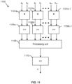
- the architecture 300 can also be implemented as a dot product unit as shown in FIG. 11 , for multiplying the two sets of floating-point numbers, in an optimised manner.
- the dot product unit 1100 comprises an multiplication unit 1101 comprising a plurality of multiplier units 1101 a , 1101 b ,... 1101 k-1 , an alignment unit comprising a plurality of shifter units 1106 a , 1106 b ,... 1106 k-1 , an accumulator unit 1108 and a normalizer unit 1110
- the dot product unit 1100 receives a large array of floating point numbers comprising a first set of k floating-point numbers (a 0 , a 1 , a 2 ... a k-1 ) and the second set of k floating-point numbers (b 0 , b 1 , b 2 ... b k-1 ).
- the plurality of multiplier units 1101 a , 1101 b , ..1101 k-1 performs multiplication of the mantissas ma i and mb i as explained with respect to FIGs 3 and 5 .
- each multiplier unit 1101 i generates two intermediate mantissa products, a first intermediate mantissa product m i ' and a second intermediate mantissa products m i " such that the sum of m i ' and m i " generates the full precision mantissa product mab i .
- This feature exploits the fact that hardware multipliers typically operate based on shifting and adding, such that the final calculation step is normally an addition of two numbers. In the present example, that final addition can be omitted, because the multiplication is followed by an addition anyway, so two inputs can be sent to the subsequent addition, rather than one (i.e. the multiplication result is in carry-save form).
- the intermediate mantissa products m i and m i ') are output with a bit length r for product numbers z i ' and z i " that is extended by one precision bit compared to that detailed above with respect to using fully resolved multiplication outputs.
- each shifter unit 1106 may comprise two shifters for shifting the product number z i ' and z i ".
- the shifter unit may comprise only one shifter unit and the product number z i ' and z i " may be provided sequentially to be shifted by the shifting unit.
- the alignment unit comprising the plurality of shifter units 1106 a , 1106 b ,... 1106 k-1 converts each product number z i ' and z i " to generate 2k numbers y i . having a second format.
- the 2k numbers y i may be represented for simplicity as k numbers y i ' and k numbers y i " generated based on the product number z i ' and z i ".
- Each shifter unit aligns the numbers y i ' and y i " having the second format based on the exponent sum and the max exponent sum as explained in detail in FIG. 3 and 5 , to generate integers v i ' and v i ".
- the numbers v i ' and v i " in the second format are provided to the accumulator 1108 which i 'is a processing unit as shown in Fig 3' or 'is an adder as shown in Fig 5 .
- the aligned number v i ' and v i " in the second format are further added by the processing unit to obtain the output o'.
- the output is further normalized by the normalizing unit 1110 to generate a normalized floating point number as the final output based on the exponent sum and the max exponent sum as explained in detail in FIG. 3 and 5 .
- the architecture eliminates a final step of generating a fully resolved multiplication output by the multiplication unit. Instead an intermediate mantissa product which is a carry save representation is converted and added together.
- the architecture 1110 reduces the carry propagate adder delay and area. However, the architecture 1110 requires twice as many shifting operations, and thus twice as many shifters (to avoid additional latency), as required for the architecture 300 or 500.
- each multiplier unit 1101 i among the plurality of multiplier units 1101 a , 1101 b , ..1101 k-1 , in the dot product unit shown in FIG. 11 performs multiplication of the mantissas ma i and mb i to generate two product numbers (z i ' and z i ") each having a bit length r+ log(k-1)+2 bits compared to the r+1 bits as explained in the above paragraph with reference to FIG.11 .
- this maintains additional precision from the multiplication into the accumulation stage of the dot product unit, by extending the multiplication output LSBs as far as the minimum additional LSB extension that would otherwise be performed at the accumulation stage.
- the product numbers (z i ' and z i ") from each multiplier unit 1101 i are provided to the shifter unit 1106 i in the alignment unit.
- the alignment unit further perform the steps as explained with respect to FIG. 3 , FIG. 5 and FIG. 11 to generate integers v i ' and v i ". Further the numbers v i ' and v i " in the second format are further processed to obtain the output of the dot product.
- FIG 8 is a graph illustrating a comparison of the implementation of the architecture 300 with other standard architectures for processing a set of floating-point numbers. This is particularly relevant to the accumulation aspect of a dot product unit. However, for clarity, it is noted that FIG. 8 is discussed more generally than the context of a dot product unit.
- FIG. 8 a graphical representation of results of a first experiment comparing the implementation of the architecture 300 explained in FIG. 3 with other standard architectures is shown.
- the first experiment includes comparing area versus delay trade-offs of the different architectures.
- three architectures (arch 1, arch 2 and arch 3) are used for comparison.
- the arch 1 is an architecture of a balanced tree of floating-point adder implementation (with pairwise round to nearest and tie to even implementation).
- the results obtained for arch 1 are represented by cross (+) symbols on a first curve in FIG. 8 .
- the arch 2 is another architecture of a balanced tree of floating-point adder implementation (with pairwise faithful rounding implementation).
- the results obtained for arch 2 are represented by circle (o) symbols on a second curve shown in FIG. 8 .
- the arch 3 is the implementation of the architecture 300 disclosed in this document (with faithful rounding implementation).
- the results obtained for arch 3 are represented by square symbols on a third curve in FIG. 8 .
- the three architectures are implemented in software using VHDL.
- the first experiment included synthesising the three architectures for various timing targets so as to observe area versus delay trade-offs. From the graph in FIG. 8 it is observed that the arch 3 (architecture 300) has the least delay and least area. In particular, the fastest circuit synthesized from architecture 300 uses less than 50% the area and has less than 50% the delay of the fastest circuits synthesized from the other architectures under consideration.
- the complexity of the hardware implementation of the different architectures are compared.
- the complexity of the hardware implementation such as the critical path is expressed using the Big O Notation.
- the maximum exponent detection unit 304 is implemented with O(log(k) log(t)) gates on the critical path (where k is the number of values being summed by the adder).
- the alignment unit 306 is implemented with O(log(r)) gates on the critical path.
- the processing unit (308) i.e. the adder 508 is implemented with O(log(k) + log(r)) gates on the critical path.
- the normalizing unit 310 is implemented with O(log(t)) gates on the critical path.
- the total hardware implementation could be implemented with O(log(k) log(t) + log(r)) logic gates on its critical path.
- the critical path is asymptotically shorter than architectures of a balanced tree of floating-point adders.
- the implementation of the architecture 300 generates output having a precision not worse than the worst case of the pairwise addition performed while using the architecture 100 of binary tree adders and multipliers or the architecture 200 of fused multiplication and addition units with faithful rounding.
- a mathematical proof for the precision of the architecture 300 is provided later. It is shown that the accuracy of the floating-point summation result is not lower than the worst-case pairwise floating-point addition with a faithful rounding scheme. This means that for any given array to be summed, performing pairwise addition by iteratively replacing two terms in the array by their sum rounded to the nearest larger or smaller representable value can always yield a result less precise or equal to the result generated by addition as part of the architecture 300 disclosed.
- An imprecise choice of ordering the inputs and for performing the step of rounding, in known architectures, is to add numbers in increasing magnitude to the largest one and always round in the same direction.
- the precision of intermediate multiplication results is also not less than in architectures 100 or 200, the precision of output obtained by the architecture 300 is not less precise than that the result obtained by making these choices.
- the delay and area performance of the architecture 300 dramatically improves compared to a tree of floating-point adders by removing intermediate normalisation steps and replacing intermediate carry propagation steps with a single carry-save addition as shown in FIG.8 .
- the empirical precision of the architecture 300 as described above is shown to significantly outperform trees of floating-point adders as measured on Gaussian distributed inputs centred around zero.
- the architecture 300 is commutative for addition, such that any order of input pairs (a i , b i ) yields the same output. This leads to better reproducibility of result, as the order in which floating point numbers in two sets are bound to the inputs to the architecture 300 does not influence the result.
- F1 is finer than F2 in the neighbourhood of r when the least upper bound and greatest lower bound of r in F2 belong to F1.
- the following proposition follows straightforwardly.
- Proposition 1 If F1 is finer than F2 in the neighbourhood of r then for all values q1, q2 such that q1 ⁇ F 1 r and q 2 ⁇ F 2 q 1 we have q 2 ⁇ F 2 r .
- H be a floating-point format with ⁇ t' exponent bits, 'r' mantissa bits including R fractional bits (and r-R explicit leading bits) and an exponent bias ⁇ c' used at the input and output of our computation.
- the mantissa is normalised and its precision reduced to hold at most R+1 non-zero consecutive bits.
- numbers in format H have a mantissa such that at least one of the r-R leading bits is '1' and when i MSBs are '0', for some 0 ⁇ i ⁇ r - R - 1, then r - R - i LSBs are '0'.
- a set of 'k' floating point numbers x 0 , ..., x k -1 in format H is given as input.
- the algorithm proceeds by conversion to a fixed-point format G aligned on the largest exponent e max in the array.
- Numbers in format G are given as a signed integer v over r + ⁇ log k ⁇ + ⁇ log k ⁇ 1 ⁇ + 2 bits, taking its value in the range ⁇ 2 r + ⁇ log k ⁇ + ⁇ log k + 1 ⁇ + 1 , ... , 2 r + ⁇ log k ⁇ + ⁇ log k ⁇ 1 ⁇ + 1 ⁇ 1 and representing the real number 2 e max ⁇ R ⁇ c ⁇ ⁇ log k ⁇ 1 ⁇ ⁇ 1 v . .
- Each input floating point number x i is converted to a fixed point value 2 e max ⁇ R ⁇ c ⁇ ⁇ log k ⁇ 1 ⁇ ⁇ 1 v i ⁇ x i G , where the choice of rounding is left to the implementation.
- numbers in the input array are classified in two categories: small numbers, whose absolute value is less than 2 e max ⁇ ⁇ log k ⁇ 1 ⁇ ⁇ 1 , and large numbers, whose exponent is at least 2 e max ⁇ ⁇ log k ⁇ 1 ⁇ ⁇ 1 .
- the input array is partitioned into an array of small numbers x 0 ′ , ... , x k ′ ⁇ 1 ′ and an array of large numbers x k ′ , ... , x k - 2 ′ , x k ⁇ 1 ′ such that the exponent of x k ⁇ 1 ′ is e max .
- the count k' of small numbers verifies 0 ⁇ k' ⁇ k - 1.
- n i ′ and e i ′ denotes the mantissa and exponent of x i ′ respectively
- v i ′ the conversion of x i ′ to the fixed-point format G , such that 2 e max ⁇ R ⁇ c ⁇ ⁇ log k ⁇ 1 ⁇ ⁇ 1 v i ′ ⁇ G x i ′ .
- e max ⁇ R ⁇ c ⁇ ⁇ log k ⁇ 1 ⁇ ⁇ 1 v i ′ ⁇ G x i ′ Remark that while small numbers may incur a rounding error, large numbers are represented exactly. This is because mantissas are normalised, hence any bit of weight less than 2 e max ⁇ R ⁇ c ⁇ ⁇ log k ⁇ 1 ⁇ ⁇ 1 in a large number is guaranteed to be '0'.
- ⁇ 2 e max ⁇ c ⁇ ⁇ log k ⁇ 1 ⁇ ⁇ 1 are representable in G, hence after rounding we have 2 e max ⁇ R ⁇ c ⁇ ⁇ log k ⁇ 1 ⁇ ⁇ 1 v k ⁇ 1 ′ ⁇ 2 e max ⁇ c ⁇ ⁇ log k ⁇ 1 ⁇ ⁇ 1 .
- each multiplication result is rounded/padded to include P fractional mantissa bits.
- the output mantissa of a multiplication in a conventional architecture 100 will be of the normalised form and have up to P+1 consecutive non-zero bits.
- every input to the alignment unit 306 is enclosed between the possible rounded values a multiplier in a conventional architecture 100 can produce. It follows that the overall precision of the dot product implementation 300 is enclosed between the smallest and largest possible values considering arbitrary accumulation order and rounding direction in a conventional architecture 100. In other words, it guarantees a pairwise faithfully rounded accuracy.
- each intermediate multiplication result includes the full p+q fractional mantissa bits.
- the internal mantissa of a multiplication in a conventional architecture 200 will be of the normalised form and have up to p+q+2 consecutive non-zero bits.
- every input to the alignment unit 306 holds the same value as the intermediate multiplication result in a conventional architecture 200. It follows that the overall precision of the dot product implementation 300 is enclosed between the smallest and largest possible values considering arbitrary accumulation order and rounding direction in a conventional architecture 200. In other words, it guarantees a triplet-wise faithfully rounded accuracy.
- Figure 9 shows a computer system in which the graphics processing systems described herein may be implemented.
- the computer system comprises a CPU 902, a GPU 904, a memory 906 and other devices 914, such as a display 916, speakers 918 and a camera 908.
- a processing block 910 (corresponding to processing blocks 110) is implemented on the GPU 904. In other examples, the processing block 910 may be implemented on the CPU 902.
- the components of the computer system can communicate with each other via a communications bus 920.
- a store 912 (corresponding to store 112) is implemented as part of the memory 906.
- FIG. 9 illustrates the implementation of a graphics processing system
- a similar block diagram could be drawn for an artificial intelligence accelerator system - for example, by replacing the GPU 904 with a Neural Network Accelerator (NNA), or adding the NNA as an additional unit.
- NNA Neural Network Accelerator
- the architecture 300 of the adder can be implemented in the NNA.
- the adder described herein may be embodied in hardware on an integrated circuit.
- any of the functions, methods, techniques, or components described above can be implemented in software, firmware, hardware (e.g., fixed logic circuitry), or any combination thereof.
- the terms “module,” “functionality,” “component”, “element”, “unit”, “block” and “logic” may be used herein to generally represent software, firmware, hardware, or any combination thereof.
- the module, functionality, component, element, unit, block, or logic represents program code that performs the specified tasks when executed on a processor.
- the algorithms and methods described herein could be performed by one or more processors executing code that causes the processor(s) to perform the algorithms/methods.
- Examples of a computer-readable storage medium include a random-access memory (RAM), read-only memory (ROM), an optical disc, flash memory, hard disk memory, and other memory devices that may use magnetic, optical, and other techniques to store instructions or other data and that can be accessed by a machine.
- RAM random-access memory
- ROM read-only memory
- optical disc flash memory
- hard disk memory and other memory devices that may use magnetic, optical, and other techniques to store instructions or other data and that can be accessed by a machine.
- Computer program code and computer readable instructions refer to any kind of executable code for processors, including code expressed in a machine language, an interpreted language, or a scripting language.
- Executable code includes binary code, machine code, bytecode, code defining an integrated circuit (such as a hardware description language or netlist), and code expressed in a programming language code such as C, Java or OpenCL.
- Executable code may be, for example, any kind of software, firmware, script, module or library which, when suitably executed, processed, interpreted, compiled, executed at a virtual machine or other software environment, cause a processor of the computer system at which the executable code is supported to perform the tasks specified by the code.
- a processor, computer, or computer system may be any kind of device, machine or dedicated circuit, or collection or portion thereof, with processing capability such that it can execute instructions.
- a processor may be any kind of general purpose or dedicated processor, such as a CPU, GPU, NNA, System-on-chip, state machine, media processor, an application-specific integrated circuit (ASIC), a programmable logic array, a field-programmable gate array (FPGA), or the like.
- a computer or computer system may comprise one or more processors.
- HDL hardware description language
- An integrated circuit definition dataset may be, for example, an integrated circuit description.
- An integrated circuit definition dataset may be in the form of computer code, for example as a netlist, code for configuring a programmable chip, as a hardware description language defining hardware suitable for manufacture in an integrated circuit at any level, including as register transfer level (RTL) code, as high-level circuit representations such as Verilog or VHDL, and as low-level circuit representations such as OASIS (RTM) and GDSII.
- RTL register transfer level
- RTM high-level circuit representations
- GDSII GDSI
- one or more intermediate user steps may be required in order for a computer system configured for generating a manufacturing definition of an integrated circuit to execute code defining an integrated circuit so as to generate the manufacturing definition of that integrated circuit.
- Figure 10 shows an example of an integrated circuit (IC) manufacturing system 1002 which is configured to manufacture an adder as described in any of the examples herein.
- the IC manufacturing system 1002 comprises a layout processing system 1004 and an integrated circuit generation system 1006.
- the IC manufacturing system 1002 is configured to receive an IC definition dataset/ hardware design (e.g. defining an adder as described in any of the examples herein), process the IC definition dataset, and generate an IC according to the IC definition dataset (e.g. which embodies an adder as described in any of the examples herein).
- the processing of the IC definition dataset configures the IC manufacturing system 1002 to manufacture an integrated circuit embodying an adder as described in any of the examples herein.
- the layout processing system 1004 is configured to receive and process the IC definition dataset/ hardware design to determine a circuit layout.
- Methods of determining a circuit layout from an IC definition dataset are known in the art, and for example may involve synthesising RTL code to determine a gate level representation of a circuit to be generated, e.g. in terms of logical components (e.g. NAND, NOR, AND, OR, MUX and FLIP-FLOP components).
- a circuit layout can be determined from the gate level representation of the circuit by determining positional information for the logical components. This may be done automatically or with user involvement in order to optimise the circuit layout.
- the layout processing system 1004 may output a circuit layout definition to the IC generation system 1006.
- a circuit layout definition may be, for example, a circuit layout description.
- the IC generation system 1006 generates an IC according to the circuit layout definition, as is known in the art.
- the IC generation system 1006 may implement a semiconductor device fabrication process to generate the IC, which may involve a multiple-step sequence of photo lithographic and chemical processing steps during which electronic circuits are gradually created on a wafer made of semiconducting material.
- the circuit layout definition may be in the form of a mask which can be used in a lithographic process for generating an IC according to the circuit definition.
- the circuit layout definition provided to the IC generation system 1006 may be in the form of computer-readable code which the IC generation system 1006 can use to form a suitable mask for use in generating an IC.
- the different processes performed by the IC manufacturing system 1002 may be implemented all in one location, e.g. by one party.
- the IC manufacturing system 1002 may be a distributed system such that some of the processes may be performed at different locations, and may be performed by different parties.
- some of the stages of: (i) synthesising RTL code representing the IC definition dataset to form a gate level representation of a circuit to be generated, (ii) generating a circuit layout based on the gate level representation, (iii) forming a mask in accordance with the circuit layout, and (iv) fabricating an integrated circuit using the mask may be performed in different locations and/or by different parties.
- processing of the integrated circuit definition dataset at an integrated circuit manufacturing system may configure the system to manufacture an adder without the IC definition dataset being processed so as to determine a circuit layout.
- an integrated circuit definition dataset may define the configuration of a reconfigurable processor, such as an FPGA, and the processing of that dataset may configure an IC manufacturing system to generate a reconfigurable processor having that defined configuration (e.g. by loading configuration data to the FPGA).
- an integrated circuit manufacturing definition dataset/ hardware design when processed in an integrated circuit manufacturing system, may cause an integrated circuit manufacturing system to generate a device as described herein.
- an integrated circuit manufacturing system when processed in an integrated circuit manufacturing system, may cause an integrated circuit manufacturing system to generate a device as described herein.
- the configuration of an integrated circuit manufacturing system in the manner described above with respect to Figure 10 by an integrated circuit manufacturing definition dataset may cause a device as described herein to be manufactured.
- an integrated circuit definition dataset could include software which runs on hardware defined at the dataset or in combination with hardware defined at the dataset.
- the IC generation system may further be configured by an integrated circuit definition dataset/ hardware design to, on manufacturing an integrated circuit, load firmware onto that integrated circuit in accordance with program code defined at the integrated circuit definition dataset or otherwise provide program code with the integrated circuit for use with the integrated circuit.
- performance improvements may include one or more of increased computational performance, reduced latency, increased throughput, and/or reduced power consumption.
- performance improvements can be traded-off against the physical implementation, thereby improving the method of manufacture. For example, a performance improvement may be traded against layout area, thereby matching the performance of a known implementation but using less silicon. This may be done, for example, by reusing functional blocks in a serialised fashion or sharing functional blocks between elements of the devices, apparatus, modules and/or systems.
Landscapes
- Engineering & Computer Science (AREA)
- Physics & Mathematics (AREA)
- General Physics & Mathematics (AREA)
- Theoretical Computer Science (AREA)
- Pure & Applied Mathematics (AREA)
- Mathematical Analysis (AREA)
- Mathematical Optimization (AREA)
- Computational Mathematics (AREA)
- Computing Systems (AREA)
- General Engineering & Computer Science (AREA)
- Mathematical Physics (AREA)
- Nonlinear Science (AREA)
- Data Mining & Analysis (AREA)
- Algebra (AREA)
- Databases & Information Systems (AREA)
- Software Systems (AREA)
- Complex Calculations (AREA)
Applications Claiming Priority (2)
| Application Number | Priority Date | Filing Date | Title |
|---|---|---|---|
| GB2202128.1A GB2615774B (en) | 2022-02-17 | 2022-02-17 | Method and system for calculating dot products |
| GB2202126.5A GB2615773B (en) | 2022-02-17 | 2022-02-17 | Method and system for calculating dot products |
Publications (1)
| Publication Number | Publication Date |
|---|---|
| EP4231134A1 true EP4231134A1 (de) | 2023-08-23 |
Family
ID=85175857
Family Applications (2)
| Application Number | Title | Priority Date | Filing Date |
|---|---|---|---|
| EP23155921.2A Pending EP4231134A1 (de) | 2022-02-17 | 2023-02-09 | Verfahren und system zur berechnung von punktprodukten |
| EP23155922.0A Pending EP4231135A1 (de) | 2022-02-17 | 2023-02-09 | Verfahren und system zur berechnung von punktprodukten |
Family Applications After (1)
| Application Number | Title | Priority Date | Filing Date |
|---|---|---|---|
| EP23155922.0A Pending EP4231135A1 (de) | 2022-02-17 | 2023-02-09 | Verfahren und system zur berechnung von punktprodukten |
Country Status (2)
| Country | Link |
|---|---|
| US (2) | US20230334117A1 (de) |
| EP (2) | EP4231134A1 (de) |
Cited By (1)
| Publication number | Priority date | Publication date | Assignee | Title |
|---|---|---|---|---|
| CN119806473A (zh) * | 2023-10-09 | 2025-04-11 | 上海复旦微电子集团股份有限公司 | 乘法运算装置 |
Families Citing this family (3)
| Publication number | Priority date | Publication date | Assignee | Title |
|---|---|---|---|---|
| US20240220323A1 (en) * | 2022-12-30 | 2024-07-04 | Intel Corporation | Apparatuses, methods, and systems for instructions for loading a tile of a matrix operations accelerator |
| US20250245007A1 (en) * | 2024-01-30 | 2025-07-31 | Texas Instruments Incorporated | Hardware acceleration for pipelined floating point operations |
| CN118312130B (zh) * | 2024-06-05 | 2024-09-20 | 北京壁仞科技开发有限公司 | 数据处理方法及装置、处理器、电子设备、存储介质 |
Citations (2)
| Publication number | Priority date | Publication date | Assignee | Title |
|---|---|---|---|---|
| US20180300105A1 (en) * | 2017-04-12 | 2018-10-18 | Intel Corporation | Mixed-precision floating-point arithmetic circuitry in specialized processing blocks |
| EP3719639A2 (de) * | 2019-03-30 | 2020-10-07 | INTEL Corporation | Systeme und verfahren zur durchführung einer gleitkommaaddition mit ausgewählter rundung |
-
2023
- 2023-02-09 EP EP23155921.2A patent/EP4231134A1/de active Pending
- 2023-02-09 EP EP23155922.0A patent/EP4231135A1/de active Pending
- 2023-02-17 US US18/111,033 patent/US20230334117A1/en active Pending
- 2023-02-17 US US18/111,178 patent/US20230333812A1/en active Pending
Patent Citations (2)
| Publication number | Priority date | Publication date | Assignee | Title |
|---|---|---|---|---|
| US20180300105A1 (en) * | 2017-04-12 | 2018-10-18 | Intel Corporation | Mixed-precision floating-point arithmetic circuitry in specialized processing blocks |
| EP3719639A2 (de) * | 2019-03-30 | 2020-10-07 | INTEL Corporation | Systeme und verfahren zur durchführung einer gleitkommaaddition mit ausgewählter rundung |
Cited By (1)
| Publication number | Priority date | Publication date | Assignee | Title |
|---|---|---|---|---|
| CN119806473A (zh) * | 2023-10-09 | 2025-04-11 | 上海复旦微电子集团股份有限公司 | 乘法运算装置 |
Also Published As
| Publication number | Publication date |
|---|---|
| EP4231135A1 (de) | 2023-08-23 |
| US20230334117A1 (en) | 2023-10-19 |
| US20230333812A1 (en) | 2023-10-19 |
Similar Documents
| Publication | Publication Date | Title |
|---|---|---|
| EP4231135A1 (de) | Verfahren und system zur berechnung von punktprodukten | |
| US20240412056A1 (en) | Hardware implementation of a deep neural network with variable output data format | |
| EP3958113B1 (de) | Verfahren und system zur verarbeitung von gleitkommazahlen | |
| Murillo et al. | Energy-efficient MAC units for fused posit arithmetic | |
| CN112740171A (zh) | 乘法和累加电路 | |
| US20230259578A1 (en) | Configurable pooling processing unit for neural network accelerator | |
| EP4160487A1 (de) | Beschleuniger eines neuronalen netzes mit konfigurierbarer pipeline | |
| KR20110105555A (ko) | 효율적인 하드웨어 구성을 갖는 몽고메리 승산기 | |
| US20230221924A1 (en) | Apparatus and Method for Processing Floating-Point Numbers | |
| US20250224921A1 (en) | Apparatus and Method for Processing Floating-Point Numbers | |
| Tatsumi et al. | Mixing low-precision formats in multiply-accumulate units for DNN training | |
| EP4254170A1 (de) | Akkumulator-hardware | |
| US20250378133A1 (en) | Shared Partial Products for a Dot Product Operation in Hardware | |
| US20250224927A1 (en) | Floating-point logarithmic number system scaling system for machine learning | |
| GB2615773A (en) | Method and system for calculating dot products | |
| Esmali Nojehdeh et al. | Energy-efficient hardware implementation of fully connected artificial neural networks using approximate arithmetic blocks | |
| GB2615774A (en) | Method and system for calculating dot products | |
| CN115079997A (zh) | 对数执行硬件高效无偏舍入的方法 | |
| JP2022101463A (ja) | 浮動小数点仮数のための丸め回路 | |
| US20250165219A1 (en) | Method and system for rounding a subnormal number | |
| US20230176817A1 (en) | Floating Point Adder | |
| US20260140698A1 (en) | Approximate addition for artificial intelligence/machine learning | |
| US20250245007A1 (en) | Hardware acceleration for pipelined floating point operations | |
| Hass | Synthesizing optimal fixed-point arithmetic for embedded signal processing | |
| de Dinechin | A flexible floating-point logarithm for reconfigurable computers LIP research report RR2010-22 |
Legal Events
| Date | Code | Title | Description |
|---|---|---|---|
| PUAI | Public reference made under article 153(3) epc to a published international application that has entered the european phase |
Free format text: ORIGINAL CODE: 0009012 |
|
| STAA | Information on the status of an ep patent application or granted ep patent |
Free format text: STATUS: THE APPLICATION HAS BEEN PUBLISHED |
|
| AK | Designated contracting states |
Kind code of ref document: A1 Designated state(s): AL AT BE BG CH CY CZ DE DK EE ES FI FR GB GR HR HU IE IS IT LI LT LU LV MC ME MK MT NL NO PL PT RO RS SE SI SK SM TR |
|
| STAA | Information on the status of an ep patent application or granted ep patent |
Free format text: STATUS: REQUEST FOR EXAMINATION WAS MADE |
|
| 17P | Request for examination filed |
Effective date: 20240130 |
|
| P01 | Opt-out of the competence of the unified patent court (upc) registered |
Effective date: 20240125 |
|
| RBV | Designated contracting states (corrected) |
Designated state(s): AL AT BE BG CH CY CZ DE DK EE ES FI FR GB GR HR HU IE IS IT LI LT LU LV MC ME MK MT NL NO PL PT RO RS SE SI SK SM TR |
|
| GRAP | Despatch of communication of intention to grant a patent |
Free format text: ORIGINAL CODE: EPIDOSNIGR1 |
|
| STAA | Information on the status of an ep patent application or granted ep patent |
Free format text: STATUS: GRANT OF PATENT IS INTENDED |
|
| INTG | Intention to grant announced |
Effective date: 20260227 |