EP4231390B1 - Künstliches graphit und verfahren zu seiner herstellung, sekundärbatterie enhaltend das künstliche graphit, und elektrisches gerät - Google Patents
Künstliches graphit und verfahren zu seiner herstellung, sekundärbatterie enhaltend das künstliche graphit, und elektrisches gerät Download PDFInfo
- Publication number
- EP4231390B1 EP4231390B1 EP21942131.0A EP21942131A EP4231390B1 EP 4231390 B1 EP4231390 B1 EP 4231390B1 EP 21942131 A EP21942131 A EP 21942131A EP 4231390 B1 EP4231390 B1 EP 4231390B1
- Authority
- EP
- European Patent Office
- Prior art keywords
- artificial graphite
- graphite material
- optionally
- negative electrode
- treatment
- Prior art date
- Legal status (The legal status is an assumption and is not a legal conclusion. Google has not performed a legal analysis and makes no representation as to the accuracy of the status listed.)
- Active
Links
Images

Classifications
-
- C—CHEMISTRY; METALLURGY
- C01—INORGANIC CHEMISTRY
- C01B—NON-METALLIC ELEMENTS; COMPOUNDS THEREOF; METALLOIDS OR COMPOUNDS THEREOF NOT COVERED BY SUBCLASS C01C
- C01B32/00—Carbon; Compounds thereof
- C01B32/20—Graphite
- C01B32/205—Preparation
-
- C—CHEMISTRY; METALLURGY
- C01—INORGANIC CHEMISTRY
- C01B—NON-METALLIC ELEMENTS; COMPOUNDS THEREOF; METALLOIDS OR COMPOUNDS THEREOF NOT COVERED BY SUBCLASS C01C
- C01B32/00—Carbon; Compounds thereof
- C01B32/20—Graphite
- C01B32/21—After-treatment
-
- H—ELECTRICITY
- H01—ELECTRIC ELEMENTS
- H01M—PROCESSES OR MEANS, e.g. BATTERIES, FOR THE DIRECT CONVERSION OF CHEMICAL ENERGY INTO ELECTRICAL ENERGY
- H01M10/00—Secondary cells; Manufacture thereof
- H01M10/05—Accumulators with non-aqueous electrolyte
- H01M10/052—Li-accumulators
- H01M10/0525—Rocking-chair batteries, i.e. batteries with lithium insertion or intercalation in both electrodes; Lithium-ion batteries
-
- H—ELECTRICITY
- H01—ELECTRIC ELEMENTS
- H01M—PROCESSES OR MEANS, e.g. BATTERIES, FOR THE DIRECT CONVERSION OF CHEMICAL ENERGY INTO ELECTRICAL ENERGY
- H01M4/00—Electrodes
- H01M4/02—Electrodes composed of, or comprising, active material
- H01M4/13—Electrodes for accumulators with non-aqueous electrolyte, e.g. for lithium-accumulators; Processes of manufacture thereof
- H01M4/133—Electrodes based on carbonaceous material, e.g. graphite-intercalation compounds or CFx
-
- H—ELECTRICITY
- H01—ELECTRIC ELEMENTS
- H01M—PROCESSES OR MEANS, e.g. BATTERIES, FOR THE DIRECT CONVERSION OF CHEMICAL ENERGY INTO ELECTRICAL ENERGY
- H01M4/00—Electrodes
- H01M4/02—Electrodes composed of, or comprising, active material
- H01M4/36—Selection of substances as active materials, active masses, active liquids
- H01M4/58—Selection of substances as active materials, active masses, active liquids of inorganic compounds other than oxides or hydroxides, e.g. sulfides, selenides, tellurides, halogenides or LiCoFy; of polyanionic structures, e.g. phosphates, silicates or borates
- H01M4/583—Carbonaceous material, e.g. graphite-intercalation compounds or CFx
- H01M4/587—Carbonaceous material, e.g. graphite-intercalation compounds or CFx for inserting or intercalating light metals
-
- C—CHEMISTRY; METALLURGY
- C01—INORGANIC CHEMISTRY
- C01P—INDEXING SCHEME RELATING TO STRUCTURAL AND PHYSICAL ASPECTS OF SOLID INORGANIC COMPOUNDS
- C01P2004/00—Particle morphology
- C01P2004/60—Particles characterised by their size
- C01P2004/61—Micrometer sized, i.e. from 1-100 micrometer
-
- C—CHEMISTRY; METALLURGY
- C01—INORGANIC CHEMISTRY
- C01P—INDEXING SCHEME RELATING TO STRUCTURAL AND PHYSICAL ASPECTS OF SOLID INORGANIC COMPOUNDS
- C01P2006/00—Physical properties of inorganic compounds
- C01P2006/10—Solid density
-
- C—CHEMISTRY; METALLURGY
- C01—INORGANIC CHEMISTRY
- C01P—INDEXING SCHEME RELATING TO STRUCTURAL AND PHYSICAL ASPECTS OF SOLID INORGANIC COMPOUNDS
- C01P2006/00—Physical properties of inorganic compounds
- C01P2006/11—Powder tap density
-
- C—CHEMISTRY; METALLURGY
- C01—INORGANIC CHEMISTRY
- C01P—INDEXING SCHEME RELATING TO STRUCTURAL AND PHYSICAL ASPECTS OF SOLID INORGANIC COMPOUNDS
- C01P2006/00—Physical properties of inorganic compounds
- C01P2006/12—Surface area
-
- C—CHEMISTRY; METALLURGY
- C01—INORGANIC CHEMISTRY
- C01P—INDEXING SCHEME RELATING TO STRUCTURAL AND PHYSICAL ASPECTS OF SOLID INORGANIC COMPOUNDS
- C01P2006/00—Physical properties of inorganic compounds
- C01P2006/40—Electric properties
-
- C—CHEMISTRY; METALLURGY
- C01—INORGANIC CHEMISTRY
- C01P—INDEXING SCHEME RELATING TO STRUCTURAL AND PHYSICAL ASPECTS OF SOLID INORGANIC COMPOUNDS
- C01P2006/00—Physical properties of inorganic compounds
- C01P2006/42—Magnetic properties
-
- C—CHEMISTRY; METALLURGY
- C01—INORGANIC CHEMISTRY
- C01P—INDEXING SCHEME RELATING TO STRUCTURAL AND PHYSICAL ASPECTS OF SOLID INORGANIC COMPOUNDS
- C01P2006/00—Physical properties of inorganic compounds
- C01P2006/90—Other properties not specified above
-
- H—ELECTRICITY
- H01—ELECTRIC ELEMENTS
- H01M—PROCESSES OR MEANS, e.g. BATTERIES, FOR THE DIRECT CONVERSION OF CHEMICAL ENERGY INTO ELECTRICAL ENERGY
- H01M4/00—Electrodes
- H01M4/02—Electrodes composed of, or comprising, active material
- H01M2004/021—Physical characteristics, e.g. porosity, surface area
-
- H—ELECTRICITY
- H01—ELECTRIC ELEMENTS
- H01M—PROCESSES OR MEANS, e.g. BATTERIES, FOR THE DIRECT CONVERSION OF CHEMICAL ENERGY INTO ELECTRICAL ENERGY
- H01M4/00—Electrodes
- H01M4/02—Electrodes composed of, or comprising, active material
- H01M2004/026—Electrodes composed of, or comprising, active material characterised by the polarity
- H01M2004/027—Negative electrodes
-
- Y—GENERAL TAGGING OF NEW TECHNOLOGICAL DEVELOPMENTS; GENERAL TAGGING OF CROSS-SECTIONAL TECHNOLOGIES SPANNING OVER SEVERAL SECTIONS OF THE IPC; TECHNICAL SUBJECTS COVERED BY FORMER USPC CROSS-REFERENCE ART COLLECTIONS [XRACs] AND DIGESTS
- Y02—TECHNOLOGIES OR APPLICATIONS FOR MITIGATION OR ADAPTATION AGAINST CLIMATE CHANGE
- Y02E—REDUCTION OF GREENHOUSE GAS [GHG] EMISSIONS, RELATED TO ENERGY GENERATION, TRANSMISSION OR DISTRIBUTION
- Y02E60/00—Enabling technologies; Technologies with a potential or indirect contribution to GHG emissions mitigation
- Y02E60/10—Energy storage using batteries
Definitions
- This application relates to the field of secondary battery technologies, and in particular, to artificial graphite as specified in any of claims 1-5 and a preparation method thereof as specified in any of claims 8-9, a secondary battery as specified in claim 10 containing such artificial graphite as a negative electrode active material, a negative electrode active material as specified in any of the claims 6-7, and an electric apparatus as specified in claim 11.
- Secondary batteries are widely applied due to their outstanding characteristics such as high energy density, zero pollution, and long service life.
- An objective of this application is to provide artificial graphite as specified in any of claims 1-5 capable of implementing high energy density and long service life, a preparation method thereof as specified in any of claims 8-9, and a negative electrode plate prepared by using such artificial graphite as a negative electrode active material, a negative electrode active material as specified in any of the claims 6-7. Further, another objective of this application is to provide a secondary battery as specified in claim 10 with high energy density and long service life and a battery module, a battery pack, and an electric apparatus as specified in claim 11 including such secondary battery. The invention is set out in the appended set of claims.
- the present invention provides the following technical solutions.
- a first aspect of this application provides an artificial graphite material A.
- the artificial graphite material A is secondary particles, where a surface roughness ⁇ A of the artificial graphite material A satisfies 6 ⁇ A ⁇ 12. In some embodiments, the artificial graphite material A satisfies 7 ⁇ A ⁇ 10.
- a true density of the artificial graphite material A is ⁇ A ⁇ 2.20 g/cm 3 , and optionally ⁇ A ⁇ 2.25 g/cm 3 .
- a median particle size by volume D v 50 A of the artificial graphite material A satisfies D v 50 A ⁇ 10 ⁇ m, and optionally 12 ⁇ m ⁇ D v 50 A ⁇ 20 ⁇ m.
- a specific surface area of the artificial graphite material A is 1.5-4.0 m 2 /g, and optionally 2.5-3.5 m 2 /g.
- a tap density of the artificial graphite material A is 0.8-1.4 g/cm 3 , and optionally 0.9-1.1 g/cm 3 .
- a graphitization degree of the artificial graphite material A is greater than 92%, and optionally 94%-97%.
- a gram capacity of the artificial graphite material A is greater than 340 mAh/g, and optionally 350-360 mAh/g.
- a second aspect of this application provides an artificial graphite material B.
- the artificial graphite material B is primary particles, where a surface roughness ⁇ B of the artificial graphite material B satisfies 2.5 ⁇ B ⁇ 5.
- the artificial graphite material B satisfies 3 ⁇ B ⁇ 4.
- a true density of the artificial graphite material B is ⁇ 2.20 g/cm 3 , and optionally ⁇ B ⁇ 2.25 g/cm 3 .
- a median particle size by volume D v 50 B of the artificial graphite material B satisfies D v 50 B ⁇ 15 ⁇ m, and optionally 5 ⁇ m ⁇ D v 50B ⁇ 12 ⁇ m.
- a specific surface area of the artificial graphite material B is 0.5-3.0m 2 /g, and optionally 1.0-2.5 m 2 /g.
- a tap density of the artificial graphite material B is 0.8-1.4 g/cm 3 , and optionally 1.1-1.3g/cm 3 .
- a graphitization degree of the artificial graphite material B is greater than 91%, and optionally 92%-94%.
- a gram capacity of the artificial graphite material B is greater than 340 mAh/g, and optionally 340-350 mAh/g.
- a third aspect of this application provides a preparation method of artificial graphite material A, including the following steps in sequence:
- a surface roughness ⁇ A of the secondary particle before graphitization treatment is 4-6.
- the performing surface roughening treatment includes:
- the performing surface roughening treatment includes:
- a fourth aspect of the present invention provides a preparation method of artificial graphite material B, including the following steps in sequence:
- a surface roughness of the primary particle before graphitization treatment is 1.5-3.
- the performing surface roughening treatment includes:
- the performing surface roughening treatment includes:
- a fifth aspect of this application provides a secondary battery.
- the secondary battery includes a negative electrode plate, where the negative electrode plate includes a negative electrode active material; the negative electrode active material includes the artificial graphite material A in this application and/or the artificial graphite material B in this application; or the negative electrode active material includes the artificial graphite material A and/or B prepared by using the method provided in the third aspect and/or the fourth aspect of this application.
- a sixth aspect of this application provides an electric apparatus, including the secondary battery provided in the fifth aspect of this application.
- the negative electrode active material includes the artificial graphite material A and/or the artificial graphite material B, and preferably includes both the artificial graphite material A and the artificial graphite material B.
- the surface roughness of graphite is properly set for the artificial graphite material A and the artificial graphite material B in this application, so as to increase a binding force between graphite and a binder and an acting force between particles of graphite, thereby reducing bounce at the instant that rollers are discharged after cold pressing, and prolonging service life and enhancing safety performance of the secondary battery.
- the increased binding force between graphite and the binder and the increased acting force between the particles of graphite helps implement a high energy density.
- the battery module, the battery pack, and the electric apparatus in this application include the secondary battery provided in this application, and therefore have at least advantages the same as those of the secondary battery.
- Ranges disclosed in this application are defined in the form of lower and upper limits, given ranges are defined by selecting lower and upper limits, and the selected lower and upper limits define boundaries of special ranges. Ranges defined in such method may or may not include end values, and any combination may be used, to be specific, any lower limit may be combined with any upper limit to form a range. For example, if ranges of 60-120 and 80-110 are provided for a specified parameter, it should be understood that ranges of 60-110 and 80-120 can also be envisioned. In addition, if minimum values of a range are given as 1 and 2, and maximum values of the range are given as 3, 4, and 5, the following ranges can all be envisioned: 1-3, 1-4, 1-5, 2-3, 2-4, and 2-5.
- a numerical range of "a-b” is an abbreviated representation of any combination of real numbers from a to b, where both a and b are real numbers.
- a numerical range of "0-5" means that all real numbers in the range of "0-5" are listed herein, and "0-5" is just an abbreviated representation of a combination of these numbers.
- a parameter is expressed as an integer greater than or equal to 2, it is equivalent to disclosure that the parameter is, for example, an integer among 2, 3, 4, 5, 6, 7, 8, 9, 10, 11, 12, and so on.
- Secondary batteries become preferred power sources of electric apparatuses due to their advantages such as high energy density, ease of carry, no memory effect, and environmental friendliness.
- a secondary battery using existing natural graphite or artificial graphite as a negative electrode active substance has an energy density not high enough to fully satisfy a requirement of high energy density and satisfy a high service life requirement. Therefore, how to further increase energy density of secondary batteries and further prolong service life of the secondary batteries has become a focus in the field of secondary battery technologies.
- a negative electrode active material being prepared by using the artificial graphite material helps a secondary battery to maintain a high energy density and also helps prolong service life and enhance safety performance of the secondary battery and a battery module, a battery pack, and an electric apparatus containing such secondary battery.
- a first aspect of this application provides an artificial graphite material A.
- the artificial graphite material A is secondary particles, where a surface roughness ⁇ A of the artificial graphite material A satisfies 6 ⁇ A ⁇ 12, and preferably 7 ⁇ A ⁇ 10.
- An appropriate surface roughness ⁇ A of the artificial graphite material A can increase a binding force between graphite and a binder and an acting force between particles of graphite, thereby reducing bounce at the instant that rollers are discharged after cold pressing, and prolonging service life and enhancing safety performance of a secondary battery.
- the increased binding force between graphite and the binder and the increased acting force between the particles of graphite help implement a high energy density.
- a true density of the artificial graphite material A in this application is ⁇ A ⁇ 2.20 g/cm 3 , and optionally ⁇ A ⁇ 2.25 g/cm 3 .
- the artificial graphite material A with an appropriate true density can have a higher gram capacity, so as to help increase gram capacity of composite artificial graphite and suppress side reactions during cycling, thereby prolonging service life and enhancing safety performance of a secondary battery.
- a median particle size by volume D v 50 A of the artificial graphite material A in this application satisfies D v 50 A ⁇ 10 ⁇ m, and optionally 12 ⁇ m ⁇ D v 50 A ⁇ 20 ⁇ m.
- An appropriate median particle size by volume of the artificial graphite material A can enable the artificial graphite material A to have a high gram capacity, thereby helping increase gram capacity of composite artificial graphite, suppressing side reactions during cycling, and prolonging service life and enhancing safety performance of the secondary battery.
- a specific surface area of the artificial graphite material A in this application is 1.5-4.0 m 2 /g, and optionally 2.5-3.5 m 2 /g.
- An excessively large specific surface area of the artificial graphite material A leads to high surface reaction activity, proneness to side reactions during cycling, and shorter service life.
- An excessively small specific surface area of the artificial graphite material A leads to fewer surface active sites and poor power performance of the material.
- a tap density of the artificial graphite material A in this application is 0.8-1.4 g/cm 3 , and optionally 0.9-1.1 g/cm 3 .
- the artificial graphite material A with a low tap density causes a slurry to have poor stability and difficulties in processing.
- An upper limit of the tap density of the artificial graphite material A is not particularly limited and may be set depending on an achievable degree in a conventional method.
- a graphitization degree of the artificial graphite material A in this application is greater than 92%, and optionally 94%-97%.
- An excessively low graphitization degree of the artificial graphite material A leads to a low capacity, and an excessively high graphitization degree of the artificial graphite material A leads to a narrow interlayer spacing and a high cycling swelling rate.
- a gram capacity of the artificial graphite material A in this application is greater than 340 mAh/g, and optionally 350-360 mAh/g.
- a higher appropriate gram capacity of the artificial graphite material A leads to a higher energy density of a secondary battery containing the artificial graphite material A.
- the artificial graphite material A provided in this application has a relatively high gram capacity, so that the secondary battery provided in this application has a high energy density.
- a third aspect of this application provides a preparation method of artificial graphite material A, including the following steps in sequence:
- the raw material in step (A1) may use, for example, one or more of green coke and calcined coke; and preferably, the raw material includes one or more of needle green petroleum coke, non-needle green petroleum coke, needle coal-based green coke, non-needle coal-based green coke, calcined needle coke, and calcined petroleum coke.
- the raw material in step (A1) may be crushed by using a device and method known in the art, for example, using a jet mill, a mechanical mill, or a roller mill.
- a large quantity of excessively small particles are usually generated during crushing, and sometimes there are also excessively large particles. Therefore, after crushing, classification may be performed based on requirements, so as to remove excessively small particles and excessively large particles from the crushed powder.
- a particle product with relatively good particle size distribution can be obtained after classification, so as to facilitate subsequent shaping and/or granulation processes.
- Classification may be performed by using a device and method known in the art, for example, a classification screen, a gravity classifier, or a centrifugal classifier.
- the crushed particle product in step (A1) may be shaped by using a device (for example, a shaping machine or another shaping device) and a method known in the art. For example, edges and corners of the resulting particle product are polished, which facilitates subsequent operations and enables the resulting product to have higher stability.
- a device for example, a shaping machine or another shaping device
- edges and corners of the resulting particle product are polished, which facilitates subsequent operations and enables the resulting product to have higher stability.
- granulation may be performed in step (A2) by using a device known in the art, for example, a granulator.
- the granulator typically includes an agitating reactor and a temperature control module for the reactor.
- a median particle size by volume of the resulting product can be controlled by regulating process conditions such as agitation speed, heating speed, granulation temperature, and cooling speed in the granulation process.
- process conditions during granulation in this application may be set as follows: an agitation speed being 800 r/min-1500 r/min, a heating speed being 8-15°C/min, a granulation temperature being 400°C-650°C, and a granulation time being 6-10 hours.
- graphitization treatment is performed in step (A3).
- Graphitization treatment includes high-temperature graphitization treatment and low-temperature graphitization treatment.
- treatment may be performed by appropriately selecting any one or two of high-temperature graphitization treatment and low-temperature graphitization treatment based on actual specific requirements; or high-temperature graphitization treatment and/or low-temperature graphitization treatment may be performed repeatedly.
- Graphite with an appropriate graphitization degree and graphite interlayer spacing can be obtained through high-temperature graphitization treatment.
- a temperature for performing high-temperature graphitization treatment in step (A3) may be 2800°C-3200°C, for example, 2900°C-3100°C or 3000°C-3200°C.
- Graphite prepared at an appropriate graphitization temperature can obtain an appropriate graphitization degree and graphite interlayer spacing, so that composite artificial graphite can obtain high structural stability and gram capacity.
- Graphite with an appropriate graphitization degree and graphite interlayer spacing can also be obtained through low-temperature graphitization treatment.
- a temperature for performing low-temperature graphitization treatment in step (A3) may be 2500°C-2700°C, for example, 2500°C-2600°C or 2600°C-2700°C.
- Graphite prepared at an appropriate graphitization temperature can obtain an appropriate graphitization degree and graphite interlayer spacing, so that composite artificial graphite can obtain high structural stability and gram capacity.
- a surface roughness ⁇ A of the secondary particle before graphitization treatment is 4-6.
- the surface roughening treatment in step (A4) includes an approach which is mainly performed by using a physical approach ("approach 1A" for short below), specifically including:
- the surface roughening treatment in step (A4) includes an approach which is mainly performed by a chemical approach ("approach 2A" for short below), specifically including:
- the surface roughening treatment performed in step (A4) may use any one or two of the approach 1A or the approach 2A; or treatment in the approach 1A and/or the approach 2Amay be performed repeatedly.
- a second aspect of this application provides an artificial graphite material B.
- the artificial graphite material B is primary particles, where a surface roughness ⁇ B of the artificial graphite material B satisfies 2.5 ⁇ B ⁇ 5, and preferably, the surface roughness ⁇ B satisfies 3 ⁇ B ⁇ 4.
- An appropriate surface roughness ⁇ B of the artificial graphite material B can increase a binding force between graphite and a binder and an acting force between particles of graphite, thereby reducing bounce at the instant that rollers are discharged after cold pressing, and prolonging service life and enhancing safety performance of a secondary battery.
- the increased binding force between graphite and the binder and the increased acting force between the particles of graphite help implement a high energy density.
- a true density of the artificial graphite material B is ⁇ B ⁇ 2.20 g/cm 3 , and optionally ⁇ B ⁇ 2.25 g/cm 3 .
- the artificial graphite material B with an appropriate true density can have a higher gram capacity, so as to help increase gram capacity of composite artificial graphite and suppress side reactions during cycling, thereby prolonging service life and enhancing safety performance of a secondary battery.
- a median particle size by volume D v 50 B of the artificial graphite material B satisfies D v 50 B ⁇ 15 ⁇ m, and optionally 5 ⁇ m ⁇ D v 50 B ⁇ 12 ⁇ m.
- An appropriate median particle size by volume of the artificial graphite material B can enable the artificial graphite material B to have a high gram capacity, thereby helping increase gram capacity of composite artificial graphite, suppressing side reactions during cycling, and prolonging service life and enhancing safety performance of a secondary battery.
- a specific surface area of the artificial graphite material B is 0.5-3.0m 2 /g, and optionally 1.0-2.5 m 2 /g.
- An excessively large specific surface area of the artificial graphite material B leads to high surface reaction activity, proneness to side reactions during cycling, and shorter service life.
- An excessively small specific surface area of the artificial graphite material B leads to fewer surface active sites and poor power performance of the material.
- a tap density of the artificial graphite material B is 0.8-1.4 g/cm 3 , and optionally 1.1-1.3 g/cm 3 .
- the artificial graphite material B with a low tap density causes a slurry to have poor stability and difficulties in processing.
- An upper limit of the tap density of the artificial graphite material B is not particularly limited and may be set depending on an achievable degree in a conventional method.
- a graphitization degree of the artificial graphite material B is greater than 91%, and optionally 92%-94%.
- An excessively low graphitization degree of the artificial graphite material B leads to a low capacity, and an excessively high graphitization degree of the artificial graphite material A leads to a narrow interlayer spacing and a high cycling swelling rate.
- a gram capacity of the artificial graphite material B is greater than 340 mAh/g, and optionally 340-350 mAh/g.
- a higher appropriate gram capacity of the artificial graphite material B leads to a higher energy density of a secondary battery containing the artificial graphite material B.
- the artificial graphite material B provided in this application has a relatively high gram capacity, so that the secondary battery provided in this application has a high energy density.
- a fourth aspect of this application provides a preparation method of artificial graphite material B, including the following steps in sequence:
- the raw material in step (B1) may use, for example, one or more of green coke and calcined coke; and preferably, the raw material includes one or more of needle green petroleum coke, non-needle green petroleum coke, needle coal-based green coke, non-needle coal-based green coke, calcined needle coke, and calcined petroleum coke.
- the raw material in step (B1) may be crushed by using a device and method known in the art, for example, using a jet mill, a mechanical mill, or a roller mill.
- a large quantity of excessively small particles are usually generated during crushing, and sometimes there are also excessively large particles. Therefore, after crushing, classification may be performed based on requirements, so as to remove excessively small particles and excessively large particles from the crushed powder.
- a particle product with relatively good particle size distribution can be obtained after classification, so as to facilitate subsequent shaping and/or granulation processes.
- Classification may be performed by using a device and method known in the art, for example, a classification screen, a gravity classifier, or a centrifugal classifier.
- the crushed particle product in step (B1) may be shaped by using a device (for example, a shaping machine or another shaping device) and a method known in the art. For example, edges and corners of the resulting particle product are polished, which facilitates subsequent operations and enables the resulting product to have higher stability.
- a device for example, a shaping machine or another shaping device
- edges and corners of the resulting particle product are polished, which facilitates subsequent operations and enables the resulting product to have higher stability.
- graphitization treatment is performed in step (B2).
- Graphitization treatment includes high-temperature graphitization treatment and low-temperature graphitization treatment.
- treatment may be performed by appropriately selecting any one or two of high-temperature graphitization treatment and low-temperature graphitization treatment based on actual specific requirements; or high-temperature graphitization treatment and/or low-temperature graphitization treatment may be performed repeatedly.
- Graphite with an appropriate graphitization degree and graphite interlayer spacing can be obtained through high-temperature graphitization treatment.
- a temperature for performing high-temperature graphitization treatment in step (B2) may be 2800°C-3200°C, for example, 2900°C-3100°C or 3000°C-3200°C.
- Graphite prepared at an appropriate graphitization temperature can obtain an appropriate graphitization degree and graphite interlayer spacing, so that composite artificial graphite can obtain high structural stability and gram capacity.
- Graphite with an appropriate graphitization degree and graphite interlayer spacing can also be obtained through low-temperature graphitization treatment.
- a temperature for performing low-temperature graphitization treatment in step (B2) may be 2500°C-2700°C, for example, 2500°C-2600°C or 2600°C-2700°C.
- Graphite prepared at an appropriate graphitization temperature can obtain an appropriate graphitization degree and graphite interlayer spacing, so that composite artificial graphite can obtain high structural stability and gram capacity.
- a surface roughness of the primary particle before graphitization treatment in step (B2) is 1.5-3.
- the surface roughening treatment is performed in step (B3) to obtain the artificial graphite material B.
- the surface roughening treatment in step (B3) includes an approach which is mainly performed by using a physical approach ("approach 1B" for short below), specifically including:
- the surface roughening treatment in step (B3) includes an approach which is mainly performed by a chemical approach ("approach 2B" for short below), specifically including:
- the surface roughening treatment performed in step (B3) may use any one or two of the approach 1B or the approach 2B; or treatment in the approach 1B and/or the approach 2B may be performed repeatedly.
- a surface roughness ⁇ A of the artificial graphite material A and a surface roughness ⁇ B of the artificial graphite material B are obtained by using the following method.
- SSA specific surface area of the artificial graphite material
- ⁇ true density of the artificial graphite material
- test data of D k and Vk can be directly read out by using a test device laser particle size analyzer (Malvern Master Size 3000)
- n particle size range of the material
- D K represents average particle size of the material within a particle size range (that is, (particle size upper limit + particle size lower limit)/2); and V k represents percentage by volume of particles within this range in all particles.
- a true density ⁇ A of the artificial graphite material A and a true density ⁇ B of the artificial graphite material B are determined in accordance with standard GB/T 24586-2009 by using a true density tester (AccuPyc).
- a median particle size by volume D v 50 A of the artificial graphite material A and a median particle size by volume D v 50 B of the artificial graphite material B are determined in accordance with standard GB/T 19077.1-2016 by using the laser particle size analyzer (Malvern Master Size 3000).
- D v 50 A and D v 50 B Physical definitions of D v 50 A and D v 50 B are as follows: D v 50 A and D v 50 B represent a corresponding particle size when a cumulative volume distribution percentage of the artificial graphite material reaches 50%.
- specific surface areas of the artificial graphite material A and the artificial graphite material B are measured with reference to GB/T 19587-2017 by using a nitrogen adsorption specific surface area analysis test method and are obtained through calculation by using a BET (Brunauer Emmett Teller) method.
- the nitrogen adsorption specific surface area analysis test may be performed by using a Tri-Star 3020 specific surface area and pore size analyzer from Micromeritics company in USA.
- tap densities of the artificial graphite material A and the artificial graphite material B are measured with reference to GB/T 5162-2006 by using a powder tap density tester (for example, Bettersize BT-301).
- powder compacted densities of the artificial graphite material A and the artificial graphite material B are measured with reference to GB/T 24533-2009 by using an electronic pressure tester (for example, UTM7305).
- UTM7305 an electronic pressure tester
- a specific amount M of powder sample under test is placed on a dedicated press mold (a base area is S), and different pressures are set. Each pressure is kept for 30 seconds and then released, and after 10 seconds, a thickness H of powder pressed under this pressure is read out on the device.
- a compacted density under this pressure is obtained through calculation, and a compacted density of a negative electrode plate material under this pressure is equal to M/(H ⁇ S).
- a graphite interlayer spacing d 002 and a graphitization degree are measured by using a method known in the art.
- the graphitization degree is measured by using an X-ray powder diffractometer (for example, Bruker D8 Discover).
- X-ray powder diffractometer for example, Bruker D8 Discover
- a value of d 002 is obtained through measurement.
- Gram capacities of the artificial graphite material A and the artificial graphite material B are measured by using a method known in the art. For example, measurement is performed by using the following method.
- An artificial graphite material prepared, a conductive agent Super P, a thickener (CMC-Na), and a binder (SBR) are uniformly mixed in a solvent deionized water at a mass ratio of 94.5:1.5:1.5:2.5 to obtain a slurry.
- the slurry prepared is applied to a copper foil current collector and dried in an oven for later use.
- a metal lithium plate is used as a counter electrode and a polyethylene (PE) film is used as a separator.
- Ethylene carbonate (EC), ethyl methyl carbonate (EMC), and diethyl carbonate (DEC) are mixed at a volume ratio of 1:1:1, and then LiPF6 is uniformly dissolved in the foregoing solution to obtain an electrolyte, where a concentration of LiPF6 is 1 mol/L. All the parts are assembled into a CR2430-type button battery in a glove box protected by argon.
- the button battery obtained After being left standing for 12 hours, the button battery obtained is discharged to 0.005 V at a constant current of 0.05C, left standing for 10 minutes, and then discharged to 0.005 V again at a constant current of 10 ⁇ A. Then the button battery obtained is charged to 2 V at a constant current of 0.1C, and a charge capacity is recorded.
- a ratio of the charge capacity to mass of composite artificial graphite is the gram capacity of the artificial graphite material prepared.
- a fifth aspect of this application provides a secondary battery.
- the secondary battery includes any one of artificial graphite materials A according to the first aspect of the present invention and/or any one of artificial graphite materials B according to the second aspect of the present invention.
- the secondary battery includes a positive electrode plate, a negative electrode plate, an electrolyte, and a separator.
- active ions are intercalated and deintercalated between the positive electrode plate and the negative electrode plate.
- the electrolyte conducts ions between the positive electrode plate and the negative electrode plate.
- the separator is disposed between the positive electrode plate and the negative electrode plate, mainly preventing short circuit between the positive electrode and the negative electrode and allowing the ions to pass through.
- the negative electrode plate includes a negative electrode current collector and a negative electrode membrane disposed on at least one surface of the negative electrode current collector.
- the negative electrode current collector has two back-to-back surfaces in its thickness direction, and the negative electrode membrane is laminated on either or both of the two back-to-back surfaces of the negative electrode current collector.
- a material with good conductivity and mechanical strength may be used as the negative electrode current collector to conduct electricity and collect current.
- a copper foil may be used as the negative electrode current collector.
- the negative electrode membrane includes a negative electrode active material.
- the negative electrode active material includes any one of artificial graphite materials A provided in the first aspect of this application and/or any one of artificial graphite materials B provided in the second aspect of this application, which can significantly reduce at the instant that rollers are discharged after cold pressing in a manufacturing process of a negative electrode plate including an artificial graphite material, thereby effectively prolonging service life and enhancing safety performance of a secondary battery.
- steps of preparing the negative electrode plate by using any one or more of the artificial graphite materials in this application may include: dissolving a negative electrode active material including any one or more of the artificial graphite materials A and/or B in this application, a binder, and optionally a thickener and conductive agent in a solvent deionized water to obtain a uniform negative electrode slurry, and applying the negative electrode slurry on a negative electrode current collector, followed by processes such as drying and cold pressing, to obtain a negative electrode plate.
- the negative electrode plate further optionally includes other negative electrode active materials used as the negative electrode of the secondary battery.
- the other negative electrode active materials may be one or more of other graphite materials (for example, other artificial graphite different from that in this application and natural graphite), mesocarbon microbeads (MCMB for short), hard carbon, soft carbon, silicon-based material, and tin-based material.
- the binder may be selected from one or more of polyacrylic acid (PAA), polyacrylic acid sodium (PAAS), polyacrylamide (PAM), polyvinyl alcohol (PVA), styrene butadiene rubber (SBR), sodium alginate (SA), polymethacrylic acid (PMAA), and carboxymethyl chitosan (CMCS).
- PAA polyacrylic acid
- PAAS polyacrylic acid sodium
- PAM polyacrylamide
- PVA polyvinyl alcohol
- SBR styrene butadiene rubber
- SA sodium alginate
- PMAA polymethacrylic acid
- CMCS carboxymethyl chitosan
- the thickener may be sodium carboxymethyl cellulose (CMC-Na).
- the conductive agent used as the negative electrode plate may be selected from one or more of graphite, superconducting carbon, acetylene black, carbon black, Ketjen black, carbon dots, carbon nanotubes, graphene, and carbon nanofiber.
- the positive electrode plate includes a positive electrode current collector and a positive electrode membrane, where the positive electrode membrane is disposed on at least one surface of the positive electrode current collector and includes a positive electrode active material.
- the positive electrode current collector has two back-to-back surfaces in its thickness direction, and the positive electrode membrane is laminated on either or both of the two back-to-back surfaces of the negative electrode current collector.
- a material with good conductivity and mechanical strength may be used as the positive electrode current collector.
- an aluminum foil may be used as the positive electrode current collector.
- the positive electrode active material is not limited to any specific type in this application, may use materials that are known in the art and can be used for positive electrodes of secondary batteries, and may be selected by persons skilled in the art based on actual demands.
- the secondary battery may be a lithium-ion secondary battery.
- the positive electrode active material may be selected from lithium transition metal oxide and modified materials thereof.
- the modified material may be lithium transition metal oxide modified through doping and/or coating.
- the lithium transition metal oxide may be selected from one or more of lithium cobalt oxide, lithium nickel oxide, lithium manganese oxide, lithium nickel manganese oxide, lithium nickel cobalt manganese oxide, lithium nickel cobalt aluminum oxide, and olivine-structured lithium-containing phosphate.
- the positive electrode active material of the secondary battery may be selected from one or more of LiCoO 2 , LiNiO 2 , LiMnO 2 , LiMn 2 O 4 , LiNi 1/3 Co 1/3 Mni /3 O 2 (NCM333), LiNi 0.5 Co 0.2 Mn 0.3 O 2 (NCM523), LiNi 0.6 Co 0.2 Mn 0.2 O 2 (NCM622), LiNi 0.8 Co 0.1 Mn 0.1 O 2 (NCM811), LiNi 0.85 Co 0.15 Al 0.05 O 2 , LiFePO 4 (LFP), and LiMnPO 4 .
- LiCoO 2 LiNiO 2 , LiMnO 2 , LiMn 2 O 4 , LiNi 1/3 Co 1/3 Mni /3 O 2 (NCM333), LiNi 0.5 Co 0.2 Mn 0.3 O 2 (NCM523), LiNi 0.6 Co 0.2 Mn 0.2 O 2 (NCM622), LiNi 0.8 Co 0.1 Mn 0.1 O
- the positive electrode membrane further optionally includes a binder.
- the binder is not limited to any specific type and may be selected by persons skilled in the art based on actual demands.
- the binder used for the positive electrode membrane may include one or more of polyvinylidene fluoride (PVDF) and polytetrafluoroethylene (PTFE).
- the positive electrode membrane further optionally includes a conductive agent.
- the conductive agent is not limited to any specific type and may be selected by persons skilled in the art based on actual demands.
- the conductive agent used for the positive electrode membrane may include one or more of graphite, superconducting carbon, acetylene black, carbon black, Ketjen black, carbon dots, carbon nanotubes, graphene, and carbon nanofiber.
- the electrolyte conducts ions between the positive electrode plate and the negative electrode plate.
- the electrolyte is not limited to any specific type in this application and may be selected based on demands.
- the electrolyte may be in a liquid state, a gel state, or an all-solid-state.
- the electrolyte is an electrolytic solution.
- the electrolytic solution includes an electrolytic salt and a solvent.
- the electrolytic salt may be selected from one or more of LiPF 6 (lithium hexafluorophosphate), LiBF 4 (lithium tetrafluoroborate), LiClO 4 (lithium perchlorate), LiAsF 6 (lithium hexafluoroborate), LiFSI (lithium bis(fluorosulfonyl)imide), LiTFSI (lithium bis(trifluoromethanesulphonyl)imide), LiTFS (lithium trifluoromethanesulfonate), LiDFOB (lithium difluorooxalatoborate), LiBOB (lithium bisoxalatoborate), LiPO 2 F 2 (lithium difluorophosphate), LiDFOP (lithium difluorophosphate), and LiTFOP (lithium tetrafluoro oxalate phosphate).
- LiPF 6 lithium hexafluorophosphate
- LiBF 4 lithium tetrafluoroborate
- the solvent may be selected from one or more of ethylene carbonate (EC), propylene carbonate (PC), ethyl methyl carbonate (EMC), diethyl carbonate (DEC), dimethyl carbonate (DMC), dipropyl carbonate (DPC), methyl propyl carbonate (MPC), ethyl propyl carbonate (EPC), butylene carbonate (BC), fluoro ethylene carbonate (FEC), methylmethyl formate (MF), methyl acetate (MA), ethyl acetate (EA), propyl acetate (PA), methyl propionate (MP), ethyl propionate (EP), propyl propionate (PP), methyl butyrate (MB), ethyl butyrate (EB), 1,4-butyrolactone (GBL), sulfolane (SF), methyl sulfonyl methane (MSM), methyl ethyl sulfone (EMS), and diethy
- the electrolytic solution further optionally includes an additive.
- the additive may include a negative electrode film-forming additive, or may include a positive electrode film-forming additive, or may include an additive capable of improving some performance of the battery, for example, an additive for improving overcharge performance of the battery, an additive for improving high-temperature performance of the battery, or an additive for improving low-temperature performance of the battery.
- Secondary batteries using an electrolytic solution and some secondary batteries using a solid electrolyte further include a separator.
- the separator is disposed between the positive electrode plate and the negative electrode plate to provide separation.
- the separator is not particularly limited in type in this application and may be any commonly known porous separator with good chemical stability and mechanical stability.
- a material of the separator may be selected from one or more of glass fiber, non-woven fabric, polyethylene, polypropylene, and polyvinylidene fluoride.
- the separator may be a single-layer film or a multilayer composite film. When the separator is a multilayer composite film, each layer may be made of the same or different materials.
- the secondary battery may include an outer package that is used for packaging the positive electrode plate, the negative electrode plate, and the electrolyte.
- the positive electrode plate, the negative electrode plate, and the separator may be stacked or wound to form a cell having a stacked structure or a cell having a wound structure.
- the cell is packaged in the outer package.
- the electrolyte may use an electrolytic solution, and the electrolytic solution infiltrates in the cell.
- the outer package of the secondary battery may be a soft pack, for example, a soft pouch.
- a material of the soft pack may be plastic, for example, may include one or more of polypropylene PP, polybutylene terephthalate PBT, and polybutylene succinate PBS.
- the outer package of the secondary battery may be a hard shell, for example, an aluminum shell.
- the positive electrode plate, the negative electrode plate, and the separator may be made into an electrode assembly through winding or stacking.
- the secondary battery is not particularly limited in shape in this application and may be cylindrical, rectangular, or of any other shapes.
- FIG. 1 shows a rectangular secondary battery 5 as an example.
- secondary batteries may be assembled into a battery module; and the battery module may include a plurality of secondary batteries, and the specific quantity of secondary batteries may be adjusted based on application and capacity of the battery module.
- FIG. 2 shows a battery module 4 as an example.
- a plurality of secondary batteries 5 may be sequentially arranged along a length direction of the battery module 4.
- the secondary batteries 5 may alternatively be arranged in any other manners.
- the plurality of secondary batteries 5 may be fastened through fasteners.
- the battery module 4 may further include a housing with an accommodating space, and the plurality of secondary batteries 5 are accommodated in the accommodating space.
- the battery module in this application may be further assembled into a battery pack, and a quantity of battery modules included in a battery pack may be adjusted based on application and capacity of the battery pack.
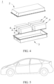
- FIG. 3 and FIG. 4 show a battery pack 1 as an example.
- the battery pack 1 may include a battery box and a plurality of battery modules 4 arranged in the battery box.
- the battery box includes an upper box body 2 and a lower box body 3.
- the upper box body 2 can cover the lower box body 3 to form an enclosed space for accommodating the battery module 4.
- the plurality of battery modules 4 may be arranged in the battery box in any manner.
- the sixth aspect of this application further provides an electric apparatus.
- the electric apparatus includes the secondary battery in this application.
- the secondary battery supplies power to the electric apparatus.
- the electric apparatus may be, but is not limited to, a mobile device (for example, a mobile phone or a notebook computer), an electric vehicle (for example, a full electric vehicle, a hybrid electric vehicle, a plug-in hybrid electric vehicle, an electric bicycle, an electric scooter, an electric golf vehicle, or an electric truck), an electric train, a ship, a satellite, an energy storage system, and the like.
- the secondary battery, the battery module, or the battery pack may be selected for the electric apparatus based on requirements for using the apparatus.
- FIG. 5 shows an electric apparatus as an example.
- the electric apparatus is a battery electric vehicle, a hybrid electric vehicle, a plug-in hybrid electric vehicle, or the like.
- a battery pack or a battery module may be used.
- the electric apparatus may be a mobile phone, a tablet computer, a notebook computer, or the like.
- Such apparatus is generally required to be light and thin and may use a secondary battery as its power source.
- the artificial graphite material A prepared, a conductive agent Super P, a binder SBR, and a thickener CMC-Na were mixed at a mass ratio of 96.2:0.8:1.8:1.2 and fully stirred in an appropriate amount of deionized water to form a uniform negative electrode slurry.
- the negative electrode slurry was applied to a surface of a negative electrode current collector copper foil, followed by drying and cold pressing (a pressure for cold pressing was 70 ton, and a cold pressing speed was 35 m/s) to obtain a negative electrode plate.
- a negative electrode membrane had a surface density of 10.7 mg/cm 2 and a compacted density of 1.71 g/cm 3 .
- a positive electrode active material LiNi 0.5 Co 0.2 Mn 0.3 O 2 (NCM523), a conductive agent (Super P), and a binder PVDF were fully stirred and mixed in an appropriate amount of NMP at a weight ratio of 96.2:2.7: 1.1 to form a uniform positive electrode slurry.
- the positive electrode slurry was applied to a surface of a positive electrode current collector aluminum foil, followed by drying and cold pressing to obtain a positive electrode plate.
- the positive electrode plate had a compacted density of 3.45 g/cm 3 and a surface density of 18.8 mg/cm 2 .
- Ethylene carbonate (EC), ethyl methyl carbonate (EMC), and diethyl carbonate (DEC) were mixed at a volume ratio of 1:1:1, and then LiPF 6 was uniformly dissolved in the foregoing solution to obtain an electrolyte, where a concentration of LiPF 6 was 1 mol/L.
- a polyethylene (PE) film was used.
- the positive electrode plate, the separator, and the negative electrode plate were stacked in sequence and wound to obtain an electrode assembly.
- the electrode assembly was placed in an outer package.
- the electrolyte was injected, followed by processes such as packaging, standing, formation, and aging to obtain a secondary battery.
- Examples 2a to 17a and Examples 1a and 2a were substantially the same as Example 1a, except for differences shown in Tables 1 to 3.
- Examples 2a to 17a and Comparative Examples 1a and 2a were the same as Example 1a unless otherwise explicitly indicated in Tables 1 to 3.
- step (A4) being "chemical” indicates that step (A4) was performed in the following manner: a material was placed in a granulation kettle and dry air was continuously injected; and temperature was increased to a specified treatment temperature at 5°C/min, and the treatment temperature was kept constant for a specified time.
- the treatment temperature and a treatment time (that is, a time for keeping temperature constant) are shown in Table 1.
- step (A4) being "physical" indicates that step (A4) was performed in the following manner: a material was placed in a fusion machine and treated at a specified rotating speed. The rotating speed and a treatment time are shown in Table 1.
- the negative electrode plate in the foregoing examples and comparative examples was taken and punched into a small disc with an area of S1 (the area S1 was measured in cm 2 ); and the small disc was weighed and its weight was recorded as M1 (M1 was measured in g).
- Thickness of a negative electrode membrane was measured (that is, thickness of a negative electrode film layer on any one surface of a negative electrode current collector was measured, where the thickness was measured in cm).
- the negative electrode membrane of the weighed negative electrode plate was wiped off; and the negative electrode collector was weighed and its weight was recorded as M0 (M0 was measured in g). With the negative electrode membrane being only disposed on one surface of the negative electrode current collector, the weight of the negative electrode membrane was equal to M1-M0; and with the negative electrode membrane being disposed on both surfaces of the negative electrode current collector, the weight of the negative electrode membrane was equal to (M1-M0)/2.
- the surface density of the negative electrode membrane the weight of the negative electrode membrane/S1.
- the compacted density of the negative electrode membrane after cold pressing the surface density of the negative electrode membrane/the thickness of the negative electrode membrane.
- the secondary battery prepared in the examples and comparative examples was charged to a charge cutoff voltage of 4.2 V at a constant current of 1C, then charged at a constant voltage until current was ⁇ 0.05C, left standing for 5 minutes, then discharged to a discharge cutoff voltage of 2.8 V at a constant current of 1C, and left standing for 5 minutes. This was one charge and discharge cycle.
- the battery was tested in the method for 600 charge and discharge cycles.
- the negative electrode plate was disassembled. Test was performed with reference to the steps of the given method 1. Then the compacted density of the negative electrode membrane after cycling was obtained and recorded in the following tables.
- the cycling swelling rate (600cys) of the negative electrode membrane (the compacted density of the negative electrode membrane after cold pressing/the compacted density of the negative electrode membrane after cycling-1) ⁇ 100%, where the compacted density of the negative electrode membrane after cold pressing is a test result in the method 1.
- step (A4) Material morphology or parameter Battery parameters Treatme nt approach of step (A4) Treatme nt conditio n of step (A4) Treatm ent time of step (A4) Morpholog y ⁇ A Compacte d density of negative electrode membran e after cold pressing Compacte d density of negative electrode membran e after cycling (600cys) Cycling swelling rate of negative electrode membran e (600cys)
- Example 2a Chemica l 400°C 1h Secondary particles 6.0 1.684 1.303 29.2%
- Example 5a Physical 800 r/m 20 min Secondary particles 11.0 1.726 1.326 30.2%
- the artificial graphite material B prepared, a conductive agent Super P, a binder SBR, and a thickener CMC-Na were mixed at a mass ratio of 96.2:0.8:1.8:1.2 and fully stirred in an appropriate amount of deionized water to form a uniform negative electrode slurry.
- the negative electrode slurry was applied to a surface of a negative electrode current collector copper foil, followed by drying and cold pressing to obtain a negative electrode plate.
- a negative electrode membrane had a surface density of 10.7 mg/cm 2 and a compacted density of 1.67g/cm 3 .
- a positive electrode active material LiNi 0.5 Co 0.2 Mn 0.3 O 2 (NCM523), a conductive agent (Super P), and a binder PVDF were fully stirred and mixed in an appropriate amount of NMP at a weight ratio of 96.2:2.7:1.1 to form a uniform positive electrode slurry.
- the positive electrode slurry was applied to a surface of a positive electrode current collector aluminum foil, followed by drying and cold pressing to obtain a positive electrode plate.
- the positive electrode plate had a compacted density of 3.45 g/cm 3 and a surface density of 18.8 mg/cm 2 .
- Ethylene carbonate (EC), ethyl methyl carbonate (EMC), and diethyl carbonate (DEC) were mixed at a volume ratio of 1:1:1, and then LiPF 6 was uniformly dissolved in the foregoing solution to obtain an electrolyte, where a concentration of LiPF 6 was 1 mol/L.
- a polyethylene (PE) film was used.
- the positive electrode plate, the separator, and the negative electrode plate were stacked in sequence and wound to obtain a cell.
- the cell was placed in an outer package, and the electrolyte was injected, followed by processes such as packaging, standing, formation, and aging to obtain a secondary battery.
- Examples 2b to 14b and Comparative Examples 1b and 2b were substantially the same as Example 1b, except for the differences shown in Tables 4 to 6.
- Examples 2b to 17b and Comparative Examples 1b and 2b were the same as Example 1b unless otherwise explicitly indicated in Tables 4 to 6.
- step (B3) being "chemical” indicates that step (B3) was performed in the following manner: a material was placed in a granulation kettle and dry air was continuously injected; and temperature was increased to a specified treatment temperature at 5°C/min, and the treatment temperature was kept constant for a specified time.
- the treatment temperature and a treatment time (that is, a time for keeping temperature constant) are shown in Table 4.
- step (B3) is "physical" indicates that step (B3) was performed in the following manner: a material was placed in a fusion machine and treated at a specified rotating speed. The rotating speed and a treatment time are shown in Table 4.
- Table 4 Process parameters of step (B3) Material morphology or parameter Electrical performance data Treatment approach of step (B3) Treatme nt conditio n of step (B3) Treatm ent time of step (B3) Morphology ⁇ B Compact ed density of negative electrod e membra ne after cold pressing Compact ed density of negative electrod e membra ne after cycling (600cys) Cycling swellin g rate of negativ e electrod e membra ne (600cys )
- Example 1b Physical 900 r/m 30 min Primary particles 3.5 1.667 1.341 24.3%
- Example 2b Chemical 400°C 1h Primary particles 2.5 1.653 1.301 27.1 %
- Example 3b Chemical 400°C 2h Primary particles 3.0
- the artificial graphite material A prepared in Example 1a, the artificial graphite material B prepared in Example 1b, a conductive agent Super P, a binder SBR, and a thickener CMC-Na were mixed at a mass ratio of 48.1:48.1:0.8: 1.8: 1.2 and fully stirred in an appropriate amount of deionized water to form a uniform negative electrode slurry.
- the negative electrode slurry was applied to a surface of a negative electrode current collector copper foil, followed by drying and cold pressing to obtain a negative electrode plate.
- a negative electrode membrane had a surface density of 10.7 mg/cm 2 and a compacted density of 1.71g/cm 3 .
- a positive electrode active material LiNi 0.5 Co 0.2 Mn 0.3 O 2 (NCM523), a conductive agent (Super P), and a binder PVDF were fully stirred and mixed in an appropriate amount of NMP at a weight ratio of 96.2:2.7: 1.1 to form a uniform positive electrode slurry.
- the positive electrode slurry was applied to a surface of a positive electrode current collector aluminum foil, followed by drying and cold pressing to obtain a positive electrode plate.
- the positive electrode plate had a compacted density of 3.45 g/cm 3 and a surface density of 18.8 mg/cm 2 .
- Ethylene carbonate (EC), ethyl methyl carbonate (EMC), and diethyl carbonate (DEC) were mixed at a volume ratio of 1:1:1, and then LiPF 6 was uniformly dissolved in the foregoing solution to obtain an electrolyte, where a concentration of LiPF 6 was 1 mol/L.
- a polyethylene (PE) film was used.
- the positive electrode plate, the separator, and the negative electrode plate were stacked in sequence and wound to obtain a cell.
- the cell was placed in an outer package, and the electrolyte was injected, followed by processes such as packaging, standing, formation, and aging to obtain a secondary battery.
- Table 7 Particle morphology Compacted density of negative electrode membrane after cold pressing Compacted density of negative electrode membrane after cycling (600cys) Cycling swelling rate of negative electrode membrane (600cys)
Landscapes
- Chemical & Material Sciences (AREA)
- Organic Chemistry (AREA)
- Inorganic Chemistry (AREA)
- General Life Sciences & Earth Sciences (AREA)
- Geology (AREA)
- Life Sciences & Earth Sciences (AREA)
- Electrochemistry (AREA)
- General Chemical & Material Sciences (AREA)
- Chemical Kinetics & Catalysis (AREA)
- Engineering & Computer Science (AREA)
- Materials Engineering (AREA)
- Manufacturing & Machinery (AREA)
- Battery Electrode And Active Subsutance (AREA)
- Carbon And Carbon Compounds (AREA)
Claims (11)
- Künstliches Graphitmaterial A, wobei das künstliche Graphitmaterial A Sekundärpartikel ist, und eine Oberflächenrauheit ηA des künstlichen Graphitmaterials A 6 ≤ ηA ≤ 12 erfüllt.
- Künstliches Graphitmaterial A nach Anspruch 1, wobei 7 ≤ ηA ≤ 10.
- Künstliches Graphitmaterial A nach Anspruch 1 oder 2, wobei die wahre Dichte des künstlichen Graphitmaterials A ρA ≥ 2,20 g/cm3 und gegebenenfalls ρA ≥ 2,25 g/cm3 beträgt.
- Künstliches Graphitmaterial A nach einem der Ansprüche 1 bis 3, wobei ein volumenbezogener Medianwert der Partikelgröße Dv50A des künstlichen Graphitmaterials A Dv50A ≥ 10 µm und gegebenenfalls 12 µm ≤ Dv50A ≤ 20 µm erfüllt.
- Künstliches Graphitmaterial A nach einem der Ansprüche 1 bis 4, wobei eine spezifische Oberfläche des künstlichen Graphitmaterials A 1,5 bis 4,0 m2/g und gegebenenfalls 2,5 bis 3,5 m2/g beträgt; und/oderwobei eine Klopfdichte des künstlichen Graphitmaterials A 0,8 bis 1,4 g/cm3 und gegebenenfalls 0,9 bis 1,1 g/cm3 beträgt; und/oderwobei ein Graphitisierungsgrad des künstlichen Graphitmaterials A größer als 92 % und gegebenenfalls 94 % bis 97 % ist; und/oderwobei eine Grammkapazität des künstlichen Graphitmaterials A größer als 340 mAh/g und gegebenenfalls 350 bis 360 mAh/g ist.
- Negativelektroden-Aktivmaterial, das folgendes einschließt:(i) künstliches Graphitmaterial A gemäß einem der Ansprüche 1 bis 5 oder hergestellt nach einem Verfahren gemäß einem der Ansprüche 8 bis 10, und(ii) künstliches Graphitmaterial B, wobei das künstliche Graphitmaterial B Primärpartikel ist, und eine Oberflächenrauheit ηB des künstlichen Graphitmaterials B 2,5 ≤ ηB ≤ 5 erfüllt.
- Negativelektroden-Aktivmaterial nach Anspruch 6, wobei 3 ≤ ηB ≤ 4; und/oderwobei eine wahre Dichte des künstlichen Graphitmaterials B ρB ≥ 2,20 g/cm3 und gegebenenfalls ρB ≥ 2,25 g/cm3 beträgt; und/oderwobei ein volumenbezogener Medianwert der Partikelgröße Dv50B des künstlichen Graphitmaterials Dv50B ≤ 15 µm und gegebenenfalls 5 µm ≤ Dv50B ≤ 12 µm erfüllt; und/oderwobei eine spezifische Oberfläche des künstlichen Graphitmaterials B 0,5 bis 3,0 m2/g und gegebenenfalls 1,0 bis 2,5 m2/g beträgt; und/oderwobei eine Klopfdichte des künstlichen Graphitmaterials B 0,8 bis 1,4 g/cm3 und gegebenenfalls 1,1 bis 1,3 g/cm3 beträgt; und/oderwobei ein Graphitisierungsgrad des künstlichen Graphitmaterials B größer als 91 % und gegebenenfalls 92 % bis 94 % ist; und/oderwobei eine Grammkapazität des künstlichen Graphitmaterials B größer als 340 mAh/g und gegebenenfalls 340 bis 350 mAh/g ist.
- Herstellungsverfahren für künstliches Graphitmaterial A, umfassend die folgenden Schritte in Folge:(A1) Bereitstellen eines Rohmaterials, und Durchführen von Zerkleinern und Formen;(A2) Durchführen von Granulieren;(A3) Durchführen von Graphitisierungsbehandlung; und(A4) Durchführen von Oberflächenaufrauungsbehandlung, um das künstliche Graphitmaterial zu erhalten, wobei das Durchführen der Oberflächenaufrauungsbehandlung umfasst:(i) Platzieren eines Materials in einer Fusionsmaschine und Durchführen von Behandlung mit einer spezifizierten Rotationsgeschwindigkeit,
wobei die spezifizierte Rotationsgeschwindigkeit 500 bis 1000 Umdrehungen/Minute (U/m) und gegebenenfalls 600 bis 800 U/m beträgt; und eine Behandlungsdauer 3 bis 60 Minuten und gegebenenfalls 5 bis 20 Minuten beträgt, oder(ii) Platzieren eines Materials in einem Granulierkessel und kontinuierliches Injizieren von trockener Luft; undErhöhen der Temperatur auf eine Behandlungstemperatur, und Durchführen von Behandlung bei der Behandlungstemperatur, wobei die Behandlungstemperatur 300 bis 800 °C und gegebenenfalls 400 bis 600 °C beträgt; undeine Behandlungsdauer 1 bis 8 h und gegebenenfalls 2 bis 4 h beträgt;wobei das künstliche Graphitmaterial A Sekundärpartikel ist, und eine Oberflächenrauheit ηA des künstlichen Graphitmaterials A 6 ≤ ηA ≤ 12 erfüllt. - Herstellungsverfahren für künstliches Graphitmaterial A nach Anspruch 8, wobei eine Oberflächenrauheit des Sekundärpartikels vor der Graphitisierungsbehandlung 4 bis 6 beträgt.
- Sekundärbatterie (5), wobei
die Sekundärbatterie (5) eine Negativelektrodenplatte umfasst, wobei die Negativelektrodenplatte ein Negativelektroden-Aktivmaterial nach einem der Ansprüche 6 bis 7 umfasst. - Elektrisches Gerät, umfassend die Sekundärbatterie (5) nach Anspruch 10.
Applications Claiming Priority (1)
| Application Number | Priority Date | Filing Date | Title |
|---|---|---|---|
| PCT/CN2021/141077 WO2023115509A1 (zh) | 2021-12-24 | 2021-12-24 | 人造石墨及其制备方法及包含所述人造石墨的二次电池和用电装置 |
Publications (3)
| Publication Number | Publication Date |
|---|---|
| EP4231390A1 EP4231390A1 (de) | 2023-08-23 |
| EP4231390A4 EP4231390A4 (de) | 2024-02-21 |
| EP4231390B1 true EP4231390B1 (de) | 2025-01-01 |
Family
ID=86901060
Family Applications (1)
| Application Number | Title | Priority Date | Filing Date |
|---|---|---|---|
| EP21942131.0A Active EP4231390B1 (de) | 2021-12-24 | 2021-12-24 | Künstliches graphit und verfahren zu seiner herstellung, sekundärbatterie enhaltend das künstliche graphit, und elektrisches gerät |
Country Status (6)
| Country | Link |
|---|---|
| US (1) | US20230307644A1 (de) |
| EP (1) | EP4231390B1 (de) |
| JP (1) | JP7603141B2 (de) |
| KR (1) | KR102950036B1 (de) |
| CN (1) | CN117355963A (de) |
| WO (1) | WO2023115509A1 (de) |
Families Citing this family (1)
| Publication number | Priority date | Publication date | Assignee | Title |
|---|---|---|---|---|
| CN119852318A (zh) * | 2024-08-30 | 2025-04-18 | 宁德时代新能源科技股份有限公司 | 负极极片、二次电池、用电装置、负极活性材料及其制备方法 |
Family Cites Families (17)
| Publication number | Priority date | Publication date | Assignee | Title |
|---|---|---|---|---|
| JP3579340B2 (ja) | 2000-09-29 | 2004-10-20 | 株式会社東芝 | 非水電解質二次電池 |
| CA2435980C (en) * | 2001-01-25 | 2008-07-29 | Hitachi Chemical Co., Ltd. | Artificial graphite particles and method for manufacturing same, nonaqueous electrolyte secondary cell negative electrode and method for manufacturing same, and lithium secondary cell |
| JP4672955B2 (ja) | 2001-08-10 | 2011-04-20 | Jfeケミカル株式会社 | リチウムイオン二次電池用負極材料およびその製造方法 |
| JP4672958B2 (ja) | 2002-10-10 | 2011-04-20 | Jfeケミカル株式会社 | 黒鉛質粒子、リチウムイオン二次電池、そのための負極材料および負極 |
| WO2006025377A1 (ja) * | 2004-08-30 | 2006-03-09 | Mitsubishi Chemical Corporation | 非水系二次電池用負極材料、非水系二次電池用負極、および非水系二次電池 |
| WO2012137770A1 (ja) | 2011-04-08 | 2012-10-11 | 住友金属工業株式会社 | 改質天然黒鉛粒子 |
| CN103811758B (zh) * | 2014-02-19 | 2016-04-20 | 新乡市赛日新能源科技有限公司 | 一种合成石墨颗粒负极材料的制备方法 |
| CN107871854A (zh) * | 2016-09-27 | 2018-04-03 | 宁波杉杉新材料科技有限公司 | 一种锂离子电池石墨负极材料二次颗粒的制备方法 |
| KR102171095B1 (ko) * | 2017-06-09 | 2020-10-28 | 주식회사 엘지화학 | 음극 활물질 및 이를 포함하는 음극 및 리튬 이차 전지 |
| US20200227746A1 (en) * | 2017-08-08 | 2020-07-16 | Showa Denko K.K. | Negative electrode active material for secondary battery, and secondary battery |
| CN110896140B (zh) * | 2018-09-13 | 2021-01-15 | 宁德时代新能源科技股份有限公司 | 富锂负极片、电芯及锂离子电池 |
| JP2020107405A (ja) | 2018-12-26 | 2020-07-09 | 昭和電工株式会社 | 電池電極用黒鉛材料及びその製造方法 |
| JP7452140B2 (ja) | 2019-03-29 | 2024-03-19 | 三菱ケミカル株式会社 | 非水系二次電池用黒鉛系負極材、非水系二次電池用負極及び非水系二次電池 |
| CN110642247B (zh) * | 2019-09-30 | 2021-05-25 | 广东凯金新能源科技股份有限公司 | 一种人造石墨负极材料及其制备方法、锂离子电池 |
| CN113207316B (zh) | 2019-12-03 | 2024-05-17 | 宁德时代新能源科技股份有限公司 | 人造石墨、二次电池、制备方法及装置 |
| CN113207313B (zh) | 2019-12-03 | 2023-12-01 | 宁德时代新能源科技股份有限公司 | 二次电池、装置、人造石墨及制备方法 |
| EP3879601B1 (de) | 2019-12-03 | 2024-05-29 | Contemporary Amperex Technology Co., Limited | Sekundärbatterie, vorrichtung, künstliches graphit und herstellungsverfahren dafür |
-
2021
- 2021-12-24 EP EP21942131.0A patent/EP4231390B1/de active Active
- 2021-12-24 CN CN202180091189.8A patent/CN117355963A/zh active Pending
- 2021-12-24 WO PCT/CN2021/141077 patent/WO2023115509A1/zh not_active Ceased
- 2021-12-24 KR KR1020237001445A patent/KR102950036B1/ko active Active
- 2021-12-24 JP JP2023502709A patent/JP7603141B2/ja active Active
-
2023
- 2023-05-18 US US18/319,500 patent/US20230307644A1/en active Pending
Also Published As
| Publication number | Publication date |
|---|---|
| KR102950036B1 (ko) | 2026-04-08 |
| JP2024503172A (ja) | 2024-01-25 |
| WO2023115509A1 (zh) | 2023-06-29 |
| EP4231390A1 (de) | 2023-08-23 |
| CN117355963A (zh) | 2024-01-05 |
| EP4231390A4 (de) | 2024-02-21 |
| US20230307644A1 (en) | 2023-09-28 |
| JP7603141B2 (ja) | 2024-12-19 |
| KR20230098560A (ko) | 2023-07-04 |
Similar Documents
| Publication | Publication Date | Title |
|---|---|---|
| JP7406625B2 (ja) | 人造黒鉛、二次電池、製造方法及び装置 | |
| CN116601798B (zh) | 碳包覆的磷酸铁锂正极活性材料、其制备方法、包含其的正极极片以及锂离子电池 | |
| JP7367201B2 (ja) | 二次電池、装置、人造黒鉛及び製造方法 | |
| JP7585314B2 (ja) | 二次電池、装置、人造黒鉛及び製造方法 | |
| JP7230221B2 (ja) | 負極活性材料、その製造方法、及びそれに関連する二次電池、電池モジュール、電池パック、並びに装置 | |
| JP2022545896A (ja) | 二次電池、電解液及び二次電池を備える装置 | |
| US20220102788A1 (en) | Secondary battery and apparatus containing the same | |
| EP4611056A1 (de) | Negativelektrodenfolie und elektrodenanordnung damit, batteriezelle, batterie und elektrische vorrichtung | |
| JP7591139B2 (ja) | 人造黒鉛及びその製造方法、及びこの人造黒鉛を含む二次電池と電力消費装置 | |
| CN119852317B (zh) | 二次电池和用电装置 | |
| US12249715B2 (en) | Composite artificial graphite and preparation method thereof, and secondary battery and power consuming device comprising the composite artificial graphite | |
| EP4231390B1 (de) | Künstliches graphit und verfahren zu seiner herstellung, sekundärbatterie enhaltend das künstliche graphit, und elektrisches gerät | |
| EP4682979A1 (de) | Verfahren zur herstellung eines positivelektrodenmaterials, positivelektrodenmaterial, positivelektrodenfolie, batterie und elektrische vorrichtung | |
| EP4693476A1 (de) | Negativelektrodenaktivmaterial, sekundärbatterie und elektrische vorrichtung | |
| EP4290612A1 (de) | Sekundärbatterie und batteriemodul, batteriepack und elektrische vorrichtung damit | |
| CN115842111B (zh) | 负极活性材料、包含其的二次电池及用电装置 | |
| EP4550475A1 (de) | Kohlenstoffhaltiges material und herstellungsverfahren dafür sowie sekundärbatterie und elektrische vorrichtung damit | |
| EP4358176A1 (de) | Positivpolteil, sekundärbatterie und elektrische vorrichtung | |
| WO2024182996A1 (zh) | 隔离膜及制备方法、电池及用电装置 |
Legal Events
| Date | Code | Title | Description |
|---|---|---|---|
| STAA | Information on the status of an ep patent application or granted ep patent |
Free format text: STATUS: UNKNOWN |
|
| STAA | Information on the status of an ep patent application or granted ep patent |
Free format text: STATUS: THE INTERNATIONAL PUBLICATION HAS BEEN MADE |
|
| PUAI | Public reference made under article 153(3) epc to a published international application that has entered the european phase |
Free format text: ORIGINAL CODE: 0009012 |
|
| STAA | Information on the status of an ep patent application or granted ep patent |
Free format text: STATUS: REQUEST FOR EXAMINATION WAS MADE |
|
| 17P | Request for examination filed |
Effective date: 20221130 |
|
| AK | Designated contracting states |
Kind code of ref document: A1 Designated state(s): AL AT BE BG CH CY CZ DE DK EE ES FI FR GB GR HR HU IE IS IT LI LT LU LV MC MK MT NL NO PL PT RO RS SE SI SK SM TR |
|
| A4 | Supplementary search report drawn up and despatched |
Effective date: 20240123 |
|
| RIC1 | Information provided on ipc code assigned before grant |
Ipc: H01M 4/02 20060101ALI20240117BHEP Ipc: C01B 32/21 20170101ALI20240117BHEP Ipc: H01M 10/0525 20100101ALI20240117BHEP Ipc: H01M 4/133 20100101ALI20240117BHEP Ipc: C01B 32/205 20170101ALI20240117BHEP Ipc: H01M 4/587 20100101AFI20240117BHEP |
|
| RAP1 | Party data changed (applicant data changed or rights of an application transferred) |
Owner name: CONTEMPORARY AMPEREX TECHNOLOGY(HONG KONG) LIMITED |
|
| GRAP | Despatch of communication of intention to grant a patent |
Free format text: ORIGINAL CODE: EPIDOSNIGR1 |
|
| STAA | Information on the status of an ep patent application or granted ep patent |
Free format text: STATUS: GRANT OF PATENT IS INTENDED |
|
| DAV | Request for validation of the european patent (deleted) | ||
| DAX | Request for extension of the european patent (deleted) | ||
| INTG | Intention to grant announced |
Effective date: 20241011 |
|
| GRAS | Grant fee paid |
Free format text: ORIGINAL CODE: EPIDOSNIGR3 |
|
| GRAA | (expected) grant |
Free format text: ORIGINAL CODE: 0009210 |
|
| STAA | Information on the status of an ep patent application or granted ep patent |
Free format text: STATUS: THE PATENT HAS BEEN GRANTED |
|
| AK | Designated contracting states |
Kind code of ref document: B1 Designated state(s): AL AT BE BG CH CY CZ DE DK EE ES FI FR GB GR HR HU IE IS IT LI LT LU LV MC MK MT NL NO PL PT RO RS SE SI SK SM TR |
|
| REG | Reference to a national code |
Ref country code: GB Ref legal event code: FG4D |
|
| REG | Reference to a national code |
Ref country code: CH Ref legal event code: EP |
|
| REG | Reference to a national code |
Ref country code: DE Ref legal event code: R096 Ref document number: 602021024525 Country of ref document: DE |
|
| REG | Reference to a national code |
Ref country code: IE Ref legal event code: FG4D |
|
| P01 | Opt-out of the competence of the unified patent court (upc) registered |
Free format text: CASE NUMBER: APP_1305/2025 Effective date: 20250109 |
|
| REG | Reference to a national code |
Ref country code: LT Ref legal event code: MG9D |
|
| REG | Reference to a national code |
Ref country code: NL Ref legal event code: MP Effective date: 20250101 |
|
| REG | Reference to a national code |
Ref country code: AT Ref legal event code: MK05 Ref document number: 1757235 Country of ref document: AT Kind code of ref document: T Effective date: 20250101 |
|
| PG25 | Lapsed in a contracting state [announced via postgrant information from national office to epo] |
Ref country code: NL Free format text: LAPSE BECAUSE OF FAILURE TO SUBMIT A TRANSLATION OF THE DESCRIPTION OR TO PAY THE FEE WITHIN THE PRESCRIBED TIME-LIMIT Effective date: 20250101 |
|
| PG25 | Lapsed in a contracting state [announced via postgrant information from national office to epo] |
Ref country code: FI Free format text: LAPSE BECAUSE OF FAILURE TO SUBMIT A TRANSLATION OF THE DESCRIPTION OR TO PAY THE FEE WITHIN THE PRESCRIBED TIME-LIMIT Effective date: 20250101 |
|
| PG25 | Lapsed in a contracting state [announced via postgrant information from national office to epo] |
Ref country code: PL Free format text: LAPSE BECAUSE OF FAILURE TO SUBMIT A TRANSLATION OF THE DESCRIPTION OR TO PAY THE FEE WITHIN THE PRESCRIBED TIME-LIMIT Effective date: 20250101 |
|
| PG25 | Lapsed in a contracting state [announced via postgrant information from national office to epo] |
Ref country code: ES Free format text: LAPSE BECAUSE OF FAILURE TO SUBMIT A TRANSLATION OF THE DESCRIPTION OR TO PAY THE FEE WITHIN THE PRESCRIBED TIME-LIMIT Effective date: 20250101 |
|
| PG25 | Lapsed in a contracting state [announced via postgrant information from national office to epo] |
Ref country code: NO Free format text: LAPSE BECAUSE OF FAILURE TO SUBMIT A TRANSLATION OF THE DESCRIPTION OR TO PAY THE FEE WITHIN THE PRESCRIBED TIME-LIMIT Effective date: 20250401 Ref country code: IS Free format text: LAPSE BECAUSE OF FAILURE TO SUBMIT A TRANSLATION OF THE DESCRIPTION OR TO PAY THE FEE WITHIN THE PRESCRIBED TIME-LIMIT Effective date: 20250501 |
|
| PG25 | Lapsed in a contracting state [announced via postgrant information from national office to epo] |
Ref country code: HR Free format text: LAPSE BECAUSE OF FAILURE TO SUBMIT A TRANSLATION OF THE DESCRIPTION OR TO PAY THE FEE WITHIN THE PRESCRIBED TIME-LIMIT Effective date: 20250101 |
|
| PG25 | Lapsed in a contracting state [announced via postgrant information from national office to epo] |
Ref country code: PT Free format text: LAPSE BECAUSE OF FAILURE TO SUBMIT A TRANSLATION OF THE DESCRIPTION OR TO PAY THE FEE WITHIN THE PRESCRIBED TIME-LIMIT Effective date: 20250502 Ref country code: LV Free format text: LAPSE BECAUSE OF FAILURE TO SUBMIT A TRANSLATION OF THE DESCRIPTION OR TO PAY THE FEE WITHIN THE PRESCRIBED TIME-LIMIT Effective date: 20250101 |
|
| PG25 | Lapsed in a contracting state [announced via postgrant information from national office to epo] |
Ref country code: BG Free format text: LAPSE BECAUSE OF FAILURE TO SUBMIT A TRANSLATION OF THE DESCRIPTION OR TO PAY THE FEE WITHIN THE PRESCRIBED TIME-LIMIT Effective date: 20250101 Ref country code: GR Free format text: LAPSE BECAUSE OF FAILURE TO SUBMIT A TRANSLATION OF THE DESCRIPTION OR TO PAY THE FEE WITHIN THE PRESCRIBED TIME-LIMIT Effective date: 20250402 |
|
| PG25 | Lapsed in a contracting state [announced via postgrant information from national office to epo] |
Ref country code: AT Free format text: LAPSE BECAUSE OF FAILURE TO SUBMIT A TRANSLATION OF THE DESCRIPTION OR TO PAY THE FEE WITHIN THE PRESCRIBED TIME-LIMIT Effective date: 20250101 |
|
| PG25 | Lapsed in a contracting state [announced via postgrant information from national office to epo] |
Ref country code: CZ Free format text: LAPSE BECAUSE OF FAILURE TO SUBMIT A TRANSLATION OF THE DESCRIPTION OR TO PAY THE FEE WITHIN THE PRESCRIBED TIME-LIMIT Effective date: 20250101 |
|
| PG25 | Lapsed in a contracting state [announced via postgrant information from national office to epo] |
Ref country code: SE Free format text: LAPSE BECAUSE OF FAILURE TO SUBMIT A TRANSLATION OF THE DESCRIPTION OR TO PAY THE FEE WITHIN THE PRESCRIBED TIME-LIMIT Effective date: 20250101 |
|
| REG | Reference to a national code |
Ref country code: DE Ref legal event code: R097 Ref document number: 602021024525 Country of ref document: DE |
|
| PG25 | Lapsed in a contracting state [announced via postgrant information from national office to epo] |
Ref country code: SM Free format text: LAPSE BECAUSE OF FAILURE TO SUBMIT A TRANSLATION OF THE DESCRIPTION OR TO PAY THE FEE WITHIN THE PRESCRIBED TIME-LIMIT Effective date: 20250101 |
|
| PG25 | Lapsed in a contracting state [announced via postgrant information from national office to epo] |
Ref country code: DK Free format text: LAPSE BECAUSE OF FAILURE TO SUBMIT A TRANSLATION OF THE DESCRIPTION OR TO PAY THE FEE WITHIN THE PRESCRIBED TIME-LIMIT Effective date: 20250101 |
|
| PG25 | Lapsed in a contracting state [announced via postgrant information from national office to epo] |
Ref country code: IT Free format text: LAPSE BECAUSE OF FAILURE TO SUBMIT A TRANSLATION OF THE DESCRIPTION OR TO PAY THE FEE WITHIN THE PRESCRIBED TIME-LIMIT Effective date: 20250101 |
|
| PG25 | Lapsed in a contracting state [announced via postgrant information from national office to epo] |
Ref country code: EE Free format text: LAPSE BECAUSE OF FAILURE TO SUBMIT A TRANSLATION OF THE DESCRIPTION OR TO PAY THE FEE WITHIN THE PRESCRIBED TIME-LIMIT Effective date: 20250101 |
|
| PG25 | Lapsed in a contracting state [announced via postgrant information from national office to epo] |
Ref country code: RO Free format text: LAPSE BECAUSE OF FAILURE TO SUBMIT A TRANSLATION OF THE DESCRIPTION OR TO PAY THE FEE WITHIN THE PRESCRIBED TIME-LIMIT Effective date: 20250101 |
|
| PG25 | Lapsed in a contracting state [announced via postgrant information from national office to epo] |
Ref country code: SK Free format text: LAPSE BECAUSE OF FAILURE TO SUBMIT A TRANSLATION OF THE DESCRIPTION OR TO PAY THE FEE WITHIN THE PRESCRIBED TIME-LIMIT Effective date: 20250101 |
|
| PLBE | No opposition filed within time limit |
Free format text: ORIGINAL CODE: 0009261 |
|
| STAA | Information on the status of an ep patent application or granted ep patent |
Free format text: STATUS: NO OPPOSITION FILED WITHIN TIME LIMIT |
|
| 26N | No opposition filed |
Effective date: 20251002 |
|
| PGFP | Annual fee paid to national office [announced via postgrant information from national office to epo] |
Ref country code: DE Payment date: 20251212 Year of fee payment: 5 |
|
| PGFP | Annual fee paid to national office [announced via postgrant information from national office to epo] |
Ref country code: GB Payment date: 20251211 Year of fee payment: 5 |
|
| PGFP | Annual fee paid to national office [announced via postgrant information from national office to epo] |
Ref country code: FR Payment date: 20251212 Year of fee payment: 5 |