EP4231465A1 - Dispositif électronique et son élément étanche à l'eau - Google Patents
Dispositif électronique et son élément étanche à l'eau Download PDFInfo
- Publication number
- EP4231465A1 EP4231465A1 EP22173538.4A EP22173538A EP4231465A1 EP 4231465 A1 EP4231465 A1 EP 4231465A1 EP 22173538 A EP22173538 A EP 22173538A EP 4231465 A1 EP4231465 A1 EP 4231465A1
- Authority
- EP
- European Patent Office
- Prior art keywords
- rib
- waterproof member
- enclosed
- enclosed rib
- plug unit
- Prior art date
- Legal status (The legal status is an assumption and is not a legal conclusion. Google has not performed a legal analysis and makes no representation as to the accuracy of the status listed.)
- Granted
Links
Images






Classifications
-
- H—ELECTRICITY
- H01—ELECTRIC ELEMENTS
- H01R—ELECTRICALLY-CONDUCTIVE CONNECTIONS; STRUCTURAL ASSOCIATIONS OF A PLURALITY OF MUTUALLY-INSULATED ELECTRICAL CONNECTING ELEMENTS; COUPLING DEVICES; CURRENT COLLECTORS
- H01R13/00—Details of coupling devices of the kinds covered by groups H01R12/70 or H01R24/00 - H01R33/00
- H01R13/46—Bases; Cases
- H01R13/52—Dustproof, splashproof, drip-proof, waterproof, or flameproof cases
- H01R13/5202—Sealing means between parts of housing or between housing part and a wall, e.g. sealing rings
-
- H—ELECTRICITY
- H01—ELECTRIC ELEMENTS
- H01R—ELECTRICALLY-CONDUCTIVE CONNECTIONS; STRUCTURAL ASSOCIATIONS OF A PLURALITY OF MUTUALLY-INSULATED ELECTRICAL CONNECTING ELEMENTS; COUPLING DEVICES; CURRENT COLLECTORS
- H01R13/00—Details of coupling devices of the kinds covered by groups H01R12/70 or H01R24/00 - H01R33/00
- H01R13/46—Bases; Cases
- H01R13/52—Dustproof, splashproof, drip-proof, waterproof, or flameproof cases
- H01R13/5219—Sealing means between coupling parts, e.g. interfacial seal
- H01R13/5221—Sealing means between coupling parts, e.g. interfacial seal having cable sealing means
-
- H—ELECTRICITY
- H01—ELECTRIC ELEMENTS
- H01R—ELECTRICALLY-CONDUCTIVE CONNECTIONS; STRUCTURAL ASSOCIATIONS OF A PLURALITY OF MUTUALLY-INSULATED ELECTRICAL CONNECTING ELEMENTS; COUPLING DEVICES; CURRENT COLLECTORS
- H01R13/00—Details of coupling devices of the kinds covered by groups H01R12/70 or H01R24/00 - H01R33/00
- H01R13/46—Bases; Cases
- H01R13/52—Dustproof, splashproof, drip-proof, waterproof, or flameproof cases
- H01R13/5213—Covers
-
- H—ELECTRICITY
- H01—ELECTRIC ELEMENTS
- H01R—ELECTRICALLY-CONDUCTIVE CONNECTIONS; STRUCTURAL ASSOCIATIONS OF A PLURALITY OF MUTUALLY-INSULATED ELECTRICAL CONNECTING ELEMENTS; COUPLING DEVICES; CURRENT COLLECTORS
- H01R13/00—Details of coupling devices of the kinds covered by groups H01R12/70 or H01R24/00 - H01R33/00
- H01R13/62—Means for facilitating engagement or disengagement of coupling parts or for holding them in engagement
- H01R13/639—Additional means for holding or locking coupling parts together, after engagement, e.g. separate keylock, retainer strap
-
- H—ELECTRICITY
- H02—GENERATION; CONVERSION OR DISTRIBUTION OF ELECTRIC POWER
- H02G—INSTALLATION OF ELECTRIC CABLES OR LINES, OR OF COMBINED OPTICAL AND ELECTRIC CABLES OR LINES
- H02G3/00—Installations of electric cables or lines or protective tubing therefor in or on buildings, equivalent structures or vehicles
- H02G3/02—Details
- H02G3/08—Distribution boxes; Connection or junction boxes
- H02G3/088—Dustproof, splashproof, drip-proof, waterproof, or flameproof casings or inlets
-
- H—ELECTRICITY
- H05—ELECTRIC TECHNIQUES NOT OTHERWISE PROVIDED FOR
- H05K—PRINTED CIRCUITS; CASINGS OR CONSTRUCTIONAL DETAILS OF ELECTRIC APPARATUS; MANUFACTURE OF ASSEMBLAGES OF ELECTRICAL COMPONENTS
- H05K5/00—Casings, cabinets or drawers for electric apparatus
- H05K5/02—Details
- H05K5/0247—Electrical details of casings, e.g. terminals, passages for cables or wiring
-
- H—ELECTRICITY
- H05—ELECTRIC TECHNIQUES NOT OTHERWISE PROVIDED FOR
- H05K—PRINTED CIRCUITS; CASINGS OR CONSTRUCTIONAL DETAILS OF ELECTRIC APPARATUS; MANUFACTURE OF ASSEMBLAGES OF ELECTRICAL COMPONENTS
- H05K5/00—Casings, cabinets or drawers for electric apparatus
- H05K5/02—Details
- H05K5/03—Covers
-
- H—ELECTRICITY
- H01—ELECTRIC ELEMENTS
- H01R—ELECTRICALLY-CONDUCTIVE CONNECTIONS; STRUCTURAL ASSOCIATIONS OF A PLURALITY OF MUTUALLY-INSULATED ELECTRICAL CONNECTING ELEMENTS; COUPLING DEVICES; CURRENT COLLECTORS
- H01R13/00—Details of coupling devices of the kinds covered by groups H01R12/70 or H01R24/00 - H01R33/00
- H01R13/46—Bases; Cases
- H01R13/502—Bases; Cases composed of different pieces
- H01R13/512—Bases; Cases composed of different pieces assembled by screw or screws
-
- H—ELECTRICITY
- H01—ELECTRIC ELEMENTS
- H01R—ELECTRICALLY-CONDUCTIVE CONNECTIONS; STRUCTURAL ASSOCIATIONS OF A PLURALITY OF MUTUALLY-INSULATED ELECTRICAL CONNECTING ELEMENTS; COUPLING DEVICES; CURRENT COLLECTORS
- H01R13/00—Details of coupling devices of the kinds covered by groups H01R12/70 or H01R24/00 - H01R33/00
- H01R13/46—Bases; Cases
- H01R13/52—Dustproof, splashproof, drip-proof, waterproof, or flameproof cases
- H01R13/5205—Sealing means between cable and housing, e.g. grommet
-
- H—ELECTRICITY
- H01—ELECTRIC ELEMENTS
- H01R—ELECTRICALLY-CONDUCTIVE CONNECTIONS; STRUCTURAL ASSOCIATIONS OF A PLURALITY OF MUTUALLY-INSULATED ELECTRICAL CONNECTING ELEMENTS; COUPLING DEVICES; CURRENT COLLECTORS
- H01R24/00—Two-part coupling devices, or either of their cooperating parts, characterised by their overall structure
- H01R24/60—Contacts spaced along planar side wall transverse to longitudinal axis of engagement
- H01R24/62—Sliding engagements with one side only, e.g. modular jack coupling devices
- H01R24/64—Sliding engagements with one side only, e.g. modular jack coupling devices for high frequency, e.g. RJ 45
Definitions
- the present disclosure relates to a waterproof member, and more particularly, to a waterproof member of an electronic device.
- outdoor network repeaters are also gradually used. Since outdoor network repeaters are affected by outdoor environment and so are prone to problems related to vapor, dust, etc., they must be equipped with a cable gland to prevent contaminations. Conventional cable glands not only have complex structures and high cost, they are also difficult to assemble and disassemble, and so it is troublesome for users when working with network cables.
- an electronic device which includes a device body, a cable, and a waterproof member.
- the device body includes a socket.
- the cable includes a plug unit and a cable body.
- the plug unit is disposed at one end of the cable body and is adapted to be connected to the socket.
- the waterproof member is sleeved over at least a portion of the plug unit.
- the waterproof member includes an elastic material.
- a waterproof member is provided that is adapted to be sleeved over a cable.
- the waterproof member includes a member body.
- a through hole is formed in the member body.
- the cable includes a plug unit and a cable body.
- the plug unit is disposed at one end of the cable body. When the plug unit is inserted to pass through the through hole, the waterproof member is sleeved over at least a portion of the plug unit.
- the waterproof member is made of elastic material, such as rubber.
- the waterproof member of the present disclosure has a simple structure and low cost and is easy to assemble.
- the waterproof member of the present disclosure is adaptable to most types of cables for providing waterproof and dustproof protections, and is convenient and easy to assemble or disassemble by users.
- the electronic device may further comprise a housing and a cover lid.
- the device body may be disposed inside the housing, and the waterproof member is disposed inside the cover lid.
- the cover lid may comprise a mounting slot.
- the waterproof member may be disposed in the mounting slot.
- the waterproof member may be tightly fitted to an inner wall of the mounting slot.
- the device body may comprise a body surface.
- the socket may be located on the body surface.
- the waterproof member may comprise an abutting surface, and the abutting surface is in contact with the body surface.
- the waterproof member may comprise a rib and a flange
- the abutting surface may be located on the flange.
- the flange may be located at one end of the waterproof member.
- the rib may be located at another end of the waterproof member.
- the rib may be tightly fitted to the inner wall of the mounting slot.
- the cover lid may be fastened to the body surface.
- the plug unit may comprise a registered jack and a protective sheath.
- the cable body may be connected to the registered jack.
- the protective sheath may be disposed on the cable body and may abut the registered jack.
- the waterproof member may be sleeved over the protective sheath.
- the waterproof member may comprise a through hole, a first enclosed rib with a first inner diameter, and a second enclosed rib with a second inner diameter, the first enclosed rib and the second enclosed rib are formed in the through hole, the first enclosed rib is located between the second enclosed rib and the abutting surface, and the first inner diameter is smaller than the second inner diameter.
- the first enclosed rib may comprise a first width.
- the second enclosed rib may comprise a second width.
- the first width may be smaller than the second width.
- the through hole may further comprise an enlarging portion.
- the second enclosed rib may be located between the enlarging portion and the first enclosed rib.
- the plug unit may comprise a registered jack connected to the cable body.
- the waterproof member may be sleeved over the registered jack and the cable body.
- the waterproof member may comprise a through hole, a first enclosed rib, and a second enclosed rib.
- the first enclosed rib and the second enclosed rib may be formed in the through hole.
- the first enclosed rib may be located between the second enclosed rib and the abutting surface and abuts the registered jack.
- the second enclosed rib may abut the cable body.
- a waterproof member adapted to be sleeved over a cable, the waterproof member comprising a member body comprising a through hole and an elastic material; wherein the cable comprises a cable body and a plug unit, the plug unit is disposed at one end of the cable body, and when the plug unit is inserted to pass through the through hole, the waterproof member is sleeved over at least a portion of the plug unit.
- the plug unit may comprise a registered jack and a protective sheath.
- the cable body may be connected to the registered jack.
- the protective sheath may be disposed on the cable body and may abut the registered jack.
- the waterproof member may be sleeved over the protective sheath.
- the waterproof member may further comprise an abutting surface, a first enclosed rib, and a second enclosed rib.
- the first enclosed rib and the second enclosed rib may be formed in the through hole.
- the first enclosed rib may be located between the second enclosed rib and the abutting surface.
- the first enclosed rib may comprise a first inner diameter
- the second enclosed rib may comprise a second inner diameter.
- the first inner diameter may be smaller than the second inner diameter.
- the first enclosed rib may comprise a first width
- the second enclosed rib comprises a second width
- the first width may be smaller than the second width.
- the through hole may further comprise an enlarging portion.
- the second enclosed rib may be located between the enlarging portion and the first enclosed rib.
- the plug unit may comprise a registered jack connected to the cable body.
- the waterproof member may be sleeved over the registered jack and the cable body.
- the waterproof member may further comprise an abutting surface, a first enclosed rib, and a second enclosed rib.
- the first enclosed rib and the second enclosed rib may be formed in the through hole, the first enclosed rib may be located between the second enclosed rib and the abutting surface and may abut the registered jack, and the second enclosed rib may abut the cable body.
- the waterproof member may further comprise a rib and a flange.
- the flange may be located at one end of the member body, the rib may be located at another end of the member body.
- the flange may comprises a recess.
- the plug unit may comprises a registered jack with an elastic arm.
- the elastic arm may be adapted to be placed in the recess.
- an electronic device D1 includes a device body 101, a cable L1, and a waterproof member 301.
- the device body 101 includes a socket 111.
- the cable L1 includes a plug unit 201 and a cable body 291, and the plug unit 201 is disposed at one end of the cable body 291 and adapted to be connected to the socket 111.
- the waterproof member 301 is sleeved over at least a portion of the plug unit 201.
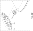
- the electronic device D1 further includes a housing 121 and a cover lid 122.
- the device body 101 is disposed inside the housing 121, and the waterproof member 301 is disposed inside the cover lid 122.
- the cover lid 122 includes a mounting slot 123 in one embodiment, and the water proof member 301 is disposed in the mounting slot 123.
- the waterproof member 301 is tightly fitted to an inner wall of the mounting slot 123.
- the device body 101 includes a body surface 131 in one embodiment.
- the socket 111 is located on the body surface 131.
- the waterproof member 301 includes an abutting surface 311, and the abutting surface 311 is in contact with the body surface 131.
- the abutting surface 311 of the waterproof member 301 contacting the body surface 131 of the device body 101 provides waterproof protection to the electronic device D1.
- the waterproof member 301 includes a rib 321 and a flange 322.
- the abutting surface 311 is located on the flange 322, and the flange 322 is located at one end of the waterproof member 301.
- the rib 321 is located at another end of the waterproof member 301 and is tightly fitted to the inner wall of the mounting slot 123. The rib 321 facilitates the installation of the waterproof member 301 to the cover lid 122 to be more convenient and prevents the waterproof member 301 from sliding in the mounting slot 123.
- the cover lid 122 is fastened and/or connected to the body surface 131 through a fastener 124 in one embodiment.
- the fastener 124 is, for example, a bolt or a screw.
- the plug unit 201 includes a registered jack 211 and a protective sheath 212.
- the cable body 291 is connected to the registered jack 211.
- the protective sheath 212 is disposed on the cable body 291 and abuts the registered jack 211.
- the waterproof member 301 is sleeved over the protective sheath 212.
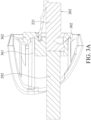
- the waterproof member 301 includes a through hole 33.
- a first enclosed rib 331 and a second enclosed rib 332 are formed in the through hole 33.
- the first enclosed rib 331 is located between the second enclosed rib 332 and the abutting surface 311.
- the first enclosed rib 331 has a first inner diameter ⁇ 1
- the second enclosed rib 332 has a second inner diameter ⁇ 2.
- the first inner diameter ⁇ 1 is smaller than the second inner diameter ⁇ 2.
- the contact surface between the cable L1 and the through hole 33 also provides waterproof protection.
- the first enclosed rib 331 has a first width d1
- the second enclosed rib 332 has a second width d2.
- the first width d1 is smaller than the second width d2.
- the through hole 33 further has an enlarging portion 333, and the second enclosed rib 332 is located between the enlarging portion 333 and the first enclosed rib 331.
- the plug unit 202 includes a registered jack 221.
- the cable body 292 is connected to the registered jack 221, and the waterproof member is sleeved over the registered jack 221 and the cable body 292.
- the waterproof member 302 includes a through hole 34.
- a first enclosed rib 341 and a second enclosed rib 342 are formed in the through hole 34.
- the first enclosed rib 341 is located between the second enclosed rib 342 and the abutting surface 312.
- the first enclosed rib 341 abuts the registered jack 221, and the second enclosed rib 342 abuts the cable body 292.
- the waterproof member 302 is adapted to be sleeved over a cable L2.
- the waterproof member 302 includes a member body 35 and the member body 35 has a through hole 34 formed therein.
- the cable L2 includes a plug unit 202 and a cable body 292.
- the plug unit 202 is disposed at one end of the cable body 292.
- the waterproof member 302 is sleeved over at least a portion of the plug unit 202.
- the contact between the cable L2 and the through hole 34 also provides waterproof protection.
- the waterproof member 302 includes a rib 361 and a flange 362.
- the flange 362 is located at one end of the member body 35, and the rib 361 is located at another end of the member body 35.
- a recess 363 is formed on the flange 362.
- the plug unit 202 includes a registered jack 221, and the registered jack 221 includes an elastic arm 223 that is adapted to be placed in the recess 363.
- the applied force must be evenly distributed around the rectangular plug unit of the cable L2 in order to achieve waterproof protection, and as such, the risk of waterproof defection caused by over-deformation due to uneven application of force is prevented.
- the cover lid 122 is able to evenly apply force on the approximately elliptical-shaped (capsule shape) waterproof member through the mounting slot 123, and the force is then further evenly distributed on the cable L2 through the squeezable characteristic of the material of the waterproof member.
- the cross-section shape of the through hole 34 may be varied.
- the part of the through hole 34 which corresponds to the registered jack 221 could have a rectangular cross-section
- the part of the through hole 34 which corresponds to the cable body 292 could have a round cross-section, thereby making the force be more evenly applied on the cable L2, but the present disclosure is not limited thereby.
- the waterproof member is made of elastic material like rubber.
- the waterproof member of the present disclosure has a simple structure and low cost, and moreover, it is easy to assemble and is adaptable to most cable types for providing waterproof protections. Furthermore, the waterproof member of the present disclosure is easy and convenient to assemble and disassemble for users.
Landscapes
- Engineering & Computer Science (AREA)
- Microelectronics & Electronic Packaging (AREA)
- Architecture (AREA)
- Civil Engineering (AREA)
- Structural Engineering (AREA)
- Connector Housings Or Holding Contact Members (AREA)
- Insertion, Bundling And Securing Of Wires For Electric Apparatuses (AREA)
- Casings For Electric Apparatus (AREA)
Priority Applications (1)
| Application Number | Priority Date | Filing Date | Title |
|---|---|---|---|
| HRP20251297TT HRP20251297T1 (hr) | 2022-02-17 | 2022-05-16 | Elektronički uređaj i njegov vodootporni element |
Applications Claiming Priority (1)
| Application Number | Priority Date | Filing Date | Title |
|---|---|---|---|
| TW111105762A TWI794013B (zh) | 2022-02-17 | 2022-02-17 | 電子裝置及其防水件 |
Publications (2)
| Publication Number | Publication Date |
|---|---|
| EP4231465A1 true EP4231465A1 (fr) | 2023-08-23 |
| EP4231465B1 EP4231465B1 (fr) | 2025-10-08 |
Family
ID=81654554
Family Applications (1)
| Application Number | Title | Priority Date | Filing Date |
|---|---|---|---|
| EP22173538.4A Active EP4231465B1 (fr) | 2022-02-17 | 2022-05-16 | Dispositif électronique et son élément étanche à l'eau |
Country Status (5)
| Country | Link |
|---|---|
| US (1) | US12142873B2 (fr) |
| EP (1) | EP4231465B1 (fr) |
| HR (1) | HRP20251297T1 (fr) |
| PL (1) | PL4231465T3 (fr) |
| TW (1) | TWI794013B (fr) |
Citations (4)
| Publication number | Priority date | Publication date | Assignee | Title |
|---|---|---|---|---|
| US5395266A (en) * | 1991-12-16 | 1995-03-07 | Yazaki Corporation | Water-proofing plug for connector |
| JP2010086766A (ja) * | 2008-09-30 | 2010-04-15 | Icom Inc | モジュラージャックの防塵構造 |
| CN206471580U (zh) * | 2017-02-28 | 2017-09-05 | 厦门汉印电子技术有限公司 | 一种具有防水网口的打印机 |
| CN208127519U (zh) * | 2018-03-28 | 2018-11-20 | 深圳市南士科技股份有限公司 | 水晶头插座及水晶头的固定结构 |
Family Cites Families (14)
| Publication number | Priority date | Publication date | Assignee | Title |
|---|---|---|---|---|
| JP2000260518A (ja) * | 1999-03-11 | 2000-09-22 | Sumitomo Wiring Syst Ltd | コネクタの防水構造 |
| US20060166554A1 (en) * | 2005-01-27 | 2006-07-27 | Liang Tei Co., Ltd | Waterproof device for electrical connector |
| US7101212B1 (en) * | 2005-03-07 | 2006-09-05 | Kevin Larkin | Snagless plug and boot connection |
| JP5599734B2 (ja) * | 2010-01-25 | 2014-10-01 | パナソニック株式会社 | 防水部材 |
| DE102012202225B4 (de) * | 2012-02-14 | 2015-10-22 | Te Connectivity Germany Gmbh | Steckergehäuse mit Dichtung |
| JP5962960B2 (ja) * | 2012-03-01 | 2016-08-03 | 株式会社ジェイテクト | 電子ユニットの防水構造 |
| CN102623837B (zh) * | 2012-04-24 | 2013-12-11 | 宁波海曙区西尚电子有限公司 | 一种数据接插件的插座及插头 |
| TWI511388B (zh) * | 2012-12-07 | 2015-12-01 | Wistron Corp | 具有防水與避震功能之連接器的電子裝置 |
| WO2014137370A1 (fr) * | 2013-03-06 | 2014-09-12 | Mimosa Networks, Inc. | Appareil étanche à l'eau pour câbles et interfaces de câbles |
| CN104332761B (zh) * | 2014-08-29 | 2018-01-16 | 中航光电科技股份有限公司 | 长解锁通信用网口插头及以太网连接器 |
| CN107026359B (zh) * | 2017-02-27 | 2019-02-22 | Oppo广东移动通信有限公司 | 防水套、连接装置及移动终端 |
| JP6590853B2 (ja) * | 2017-03-14 | 2019-10-16 | 株式会社オートネットワーク技術研究所 | コネクタの防水構造 |
| CN110251260B (zh) | 2019-06-28 | 2022-05-17 | 苏州佳世达光电有限公司 | 口腔扫描机 |
| JP7218072B2 (ja) * | 2020-12-16 | 2023-02-06 | 矢崎総業株式会社 | 防水コネクタ及びコネクタ付き機器 |
-
2022
- 2022-02-17 TW TW111105762A patent/TWI794013B/zh active
- 2022-04-18 US US17/722,750 patent/US12142873B2/en active Active
- 2022-05-16 HR HRP20251297TT patent/HRP20251297T1/hr unknown
- 2022-05-16 EP EP22173538.4A patent/EP4231465B1/fr active Active
- 2022-05-16 PL PL22173538.4T patent/PL4231465T3/pl unknown
Patent Citations (4)
| Publication number | Priority date | Publication date | Assignee | Title |
|---|---|---|---|---|
| US5395266A (en) * | 1991-12-16 | 1995-03-07 | Yazaki Corporation | Water-proofing plug for connector |
| JP2010086766A (ja) * | 2008-09-30 | 2010-04-15 | Icom Inc | モジュラージャックの防塵構造 |
| CN206471580U (zh) * | 2017-02-28 | 2017-09-05 | 厦门汉印电子技术有限公司 | 一种具有防水网口的打印机 |
| CN208127519U (zh) * | 2018-03-28 | 2018-11-20 | 深圳市南士科技股份有限公司 | 水晶头插座及水晶头的固定结构 |
Also Published As
| Publication number | Publication date |
|---|---|
| PL4231465T3 (pl) | 2026-01-26 |
| EP4231465B1 (fr) | 2025-10-08 |
| TWI794013B (zh) | 2023-02-21 |
| HRP20251297T1 (hr) | 2026-02-27 |
| US12142873B2 (en) | 2024-11-12 |
| US20230261411A1 (en) | 2023-08-17 |
| TW202334777A (zh) | 2023-09-01 |
Similar Documents
| Publication | Publication Date | Title |
|---|---|---|
| US6943296B2 (en) | USB wall plate | |
| US7357579B2 (en) | Connection device with a cable gland having housing parts enabling relative movement therebetween | |
| US4822293A (en) | Bell housing sealing assembly for mounted connector | |
| US4684210A (en) | Light transmission device | |
| US8057249B1 (en) | Electrical connector with slim-line cap | |
| KR20020006481A (ko) | 이중 기능의 먼지 덮개 | |
| CA2400560A1 (fr) | Connecteur de signal de donnees a surmoulage de protection | |
| US7973237B2 (en) | Outlet assembly | |
| JPH1126097A (ja) | パネル取り付け用ソケット | |
| EP0754401B1 (fr) | Connexion et blindage de cable | |
| EP4231465A1 (fr) | Dispositif électronique et son élément étanche à l'eau | |
| JPS5823177A (ja) | 速復型電気コネクタの遮蔽用カバ− | |
| KR101051862B1 (ko) | 광 리셉터클 | |
| KR20010005607A (ko) | 케이블 트랜싯 | |
| US11955718B2 (en) | Waterproof microphone kit and electronic device | |
| US20060141858A1 (en) | Integrated sealable plate system and method | |
| AU654509B2 (en) | Housing providing protection against electromagnetic interference for an electrical connection device | |
| EP1832905B1 (fr) | Interface de connexion de panneau protégée | |
| US5741156A (en) | Protective cover for electrical connector | |
| JPH0447478B2 (fr) | ||
| WO2020084856A1 (fr) | Dispositif de mise à la terre de câble | |
| JPH1186926A (ja) | 同軸ケーブル接続器 | |
| WO2020084857A1 (fr) | Élément de montage | |
| US20230178939A1 (en) | Electronic device and socket module and metal shielding frame thereof | |
| JPS6236357Y2 (fr) |
Legal Events
| Date | Code | Title | Description |
|---|---|---|---|
| PUAI | Public reference made under article 153(3) epc to a published international application that has entered the european phase |
Free format text: ORIGINAL CODE: 0009012 |
|
| STAA | Information on the status of an ep patent application or granted ep patent |
Free format text: STATUS: THE APPLICATION HAS BEEN PUBLISHED |
|
| AK | Designated contracting states |
Kind code of ref document: A1 Designated state(s): AL AT BE BG CH CY CZ DE DK EE ES FI FR GB GR HR HU IE IS IT LI LT LU LV MC MK MT NL NO PL PT RO RS SE SI SK SM TR |
|
| STAA | Information on the status of an ep patent application or granted ep patent |
Free format text: STATUS: REQUEST FOR EXAMINATION WAS MADE |
|
| 17P | Request for examination filed |
Effective date: 20240213 |
|
| RBV | Designated contracting states (corrected) |
Designated state(s): AL AT BE BG CH CY CZ DE DK EE ES FI FR GB GR HR HU IE IS IT LI LT LU LV MC MK MT NL NO PL PT RO RS SE SI SK SM TR |
|
| GRAP | Despatch of communication of intention to grant a patent |
Free format text: ORIGINAL CODE: EPIDOSNIGR1 |
|
| STAA | Information on the status of an ep patent application or granted ep patent |
Free format text: STATUS: GRANT OF PATENT IS INTENDED |
|
| RIC1 | Information provided on ipc code assigned before grant |
Ipc: H01R 24/64 20110101ALN20250401BHEP Ipc: H01R 13/512 20060101ALN20250401BHEP Ipc: H02G 3/08 20060101ALI20250401BHEP Ipc: H01R 13/52 20060101AFI20250401BHEP |
|
| RIC1 | Information provided on ipc code assigned before grant |
Ipc: H01R 24/64 20110101ALN20250404BHEP Ipc: H01R 13/512 20060101ALN20250404BHEP Ipc: H02G 3/08 20060101ALI20250404BHEP Ipc: H01R 13/52 20060101AFI20250404BHEP |
|
| INTG | Intention to grant announced |
Effective date: 20250417 |
|
| RAP3 | Party data changed (applicant data changed or rights of an application transferred) |
Owner name: WISTRON NEWEB CORP. |
|
| GRAS | Grant fee paid |
Free format text: ORIGINAL CODE: EPIDOSNIGR3 |
|
| GRAA | (expected) grant |
Free format text: ORIGINAL CODE: 0009210 |
|
| STAA | Information on the status of an ep patent application or granted ep patent |
Free format text: STATUS: THE PATENT HAS BEEN GRANTED |
|
| AK | Designated contracting states |
Kind code of ref document: B1 Designated state(s): AL AT BE BG CH CY CZ DE DK EE ES FI FR GB GR HR HU IE IS IT LI LT LU LV MC MK MT NL NO PL PT RO RS SE SI SK SM TR |
|
| RAP3 | Party data changed (applicant data changed or rights of an application transferred) |
Owner name: WNC CORPORATION |
|
| REG | Reference to a national code |
Ref country code: GB Ref legal event code: FG4D Ref country code: CH Ref legal event code: F10 Free format text: ST27 STATUS EVENT CODE: U-0-0-F10-F00 (AS PROVIDED BY THE NATIONAL OFFICE) Effective date: 20251008 |
|
| REG | Reference to a national code |
Ref country code: DE Ref legal event code: R096 Ref document number: 602022022570 Country of ref document: DE |
|
| REG | Reference to a national code |
Ref country code: IE Ref legal event code: FG4D |
|
| REG | Reference to a national code |
Ref country code: SK Ref legal event code: T3 Ref document number: E 47570 Country of ref document: SK |
|
| REG | Reference to a national code |
Ref country code: NL Ref legal event code: MP Effective date: 20251008 |
|
| REG | Reference to a national code |
Ref country code: HR Ref legal event code: T1PR Ref document number: P20251297 Country of ref document: HR |
|
| PG25 | Lapsed in a contracting state [announced via postgrant information from national office to epo] |
Ref country code: NL Free format text: LAPSE BECAUSE OF FAILURE TO SUBMIT A TRANSLATION OF THE DESCRIPTION OR TO PAY THE FEE WITHIN THE PRESCRIBED TIME-LIMIT Effective date: 20251008 |
|
| PG25 | Lapsed in a contracting state [announced via postgrant information from national office to epo] |
Ref country code: ES Free format text: LAPSE BECAUSE OF FAILURE TO SUBMIT A TRANSLATION OF THE DESCRIPTION OR TO PAY THE FEE WITHIN THE PRESCRIBED TIME-LIMIT Effective date: 20251008 |
|
| REG | Reference to a national code |
Ref country code: LT Ref legal event code: MG9D |
|
| PG25 | Lapsed in a contracting state [announced via postgrant information from national office to epo] |
Ref country code: NO Free format text: LAPSE BECAUSE OF FAILURE TO SUBMIT A TRANSLATION OF THE DESCRIPTION OR TO PAY THE FEE WITHIN THE PRESCRIBED TIME-LIMIT Effective date: 20260108 |
|
| PG25 | Lapsed in a contracting state [announced via postgrant information from national office to epo] |
Ref country code: FI Free format text: LAPSE BECAUSE OF FAILURE TO SUBMIT A TRANSLATION OF THE DESCRIPTION OR TO PAY THE FEE WITHIN THE PRESCRIBED TIME-LIMIT Effective date: 20251008 |
|
| PG25 | Lapsed in a contracting state [announced via postgrant information from national office to epo] |
Ref country code: RS Free format text: LAPSE BECAUSE OF FAILURE TO SUBMIT A TRANSLATION OF THE DESCRIPTION OR TO PAY THE FEE WITHIN THE PRESCRIBED TIME-LIMIT Effective date: 20260108 |
|
| PG25 | Lapsed in a contracting state [announced via postgrant information from national office to epo] |
Ref country code: IS Free format text: LAPSE BECAUSE OF FAILURE TO SUBMIT A TRANSLATION OF THE DESCRIPTION OR TO PAY THE FEE WITHIN THE PRESCRIBED TIME-LIMIT Effective date: 20260208 |
|
| PG25 | Lapsed in a contracting state [announced via postgrant information from national office to epo] |
Ref country code: PT Free format text: LAPSE BECAUSE OF FAILURE TO SUBMIT A TRANSLATION OF THE DESCRIPTION OR TO PAY THE FEE WITHIN THE PRESCRIBED TIME-LIMIT Effective date: 20260209 |
|
| PG25 | Lapsed in a contracting state [announced via postgrant information from national office to epo] |
Ref country code: LV Free format text: LAPSE BECAUSE OF FAILURE TO SUBMIT A TRANSLATION OF THE DESCRIPTION OR TO PAY THE FEE WITHIN THE PRESCRIBED TIME-LIMIT Effective date: 20251008 |