EP4231480A1 - Procédé et appareil de commande de système de production d'énergie photovoltaïque, optimiseur de puissance et support de stockage - Google Patents
Procédé et appareil de commande de système de production d'énergie photovoltaïque, optimiseur de puissance et support de stockage Download PDFInfo
- Publication number
- EP4231480A1 EP4231480A1 EP21946882.4A EP21946882A EP4231480A1 EP 4231480 A1 EP4231480 A1 EP 4231480A1 EP 21946882 A EP21946882 A EP 21946882A EP 4231480 A1 EP4231480 A1 EP 4231480A1
- Authority
- EP
- European Patent Office
- Prior art keywords
- power
- voltage
- segment
- output
- curve
- Prior art date
- Legal status (The legal status is an assumption and is not a legal conclusion. Google has not performed a legal analysis and makes no representation as to the accuracy of the status listed.)
- Pending
Links
Images

Classifications
-
- H—ELECTRICITY
- H02—GENERATION; CONVERSION OR DISTRIBUTION OF ELECTRIC POWER
- H02J—ELECTRIC POWER NETWORKS; CIRCUIT ARRANGEMENTS OR SYSTEMS FOR SUPPLYING OR DISTRIBUTING ELECTRIC POWER; SYSTEMS FOR STORING ELECTRIC ENERGY
- H02J3/00—Circuit arrangements for AC mains or AC distribution networks
- H02J3/38—Arrangements for feeding a single network from two or more generators or sources in parallel; Arrangements for feeding already energised networks from additional generators or sources in parallel
- H02J3/381—Dispersed generators
-
- G—PHYSICS
- G05—CONTROLLING; REGULATING
- G05F—SYSTEMS FOR REGULATING ELECTRIC OR MAGNETIC VARIABLES
- G05F1/00—Automatic systems in which deviations of an electric quantity from one or more predetermined values are detected at the output of the system and fed back to a device within the system to restore the detected quantity to its predetermined value or values, i.e. retroactive systems
- G05F1/66—Regulating electric power
- G05F1/67—Regulating electric power to the maximum power available from a generator, e.g. from solar cell
-
- G—PHYSICS
- G05—CONTROLLING; REGULATING
- G05F—SYSTEMS FOR REGULATING ELECTRIC OR MAGNETIC VARIABLES
- G05F3/00—Non-retroactive systems for regulating electric variables by using an uncontrolled element, or an uncontrolled combination of elements, such element or such combination having self-regulating properties
- G05F3/02—Regulating voltage or current
- G05F3/08—Regulating voltage or current wherein the variable is DC
- G05F3/10—Regulating voltage or current wherein the variable is DC using uncontrolled devices with non-linear characteristics
- G05F3/16—Regulating voltage or current wherein the variable is DC using uncontrolled devices with non-linear characteristics being semiconductor devices
- G05F3/20—Regulating voltage or current wherein the variable is DC using uncontrolled devices with non-linear characteristics being semiconductor devices using diode- transistor combinations
- G05F3/24—Regulating voltage or current wherein the variable is DC using uncontrolled devices with non-linear characteristics being semiconductor devices using diode- transistor combinations wherein the transistors are of the field-effect type only
-
- H—ELECTRICITY
- H02—GENERATION; CONVERSION OR DISTRIBUTION OF ELECTRIC POWER
- H02J—ELECTRIC POWER NETWORKS; CIRCUIT ARRANGEMENTS OR SYSTEMS FOR SUPPLYING OR DISTRIBUTING ELECTRIC POWER; SYSTEMS FOR STORING ELECTRIC ENERGY
- H02J2101/00—Supply or distribution of decentralised, dispersed or local electric power generation
- H02J2101/20—Dispersed power generation using renewable energy sources
- H02J2101/22—Solar energy
- H02J2101/24—Photovoltaics
-
- H—ELECTRICITY
- H02—GENERATION; CONVERSION OR DISTRIBUTION OF ELECTRIC POWER
- H02J—ELECTRIC POWER NETWORKS; CIRCUIT ARRANGEMENTS OR SYSTEMS FOR SUPPLYING OR DISTRIBUTING ELECTRIC POWER; SYSTEMS FOR STORING ELECTRIC ENERGY
- H02J2101/00—Supply or distribution of decentralised, dispersed or local electric power generation
- H02J2101/20—Dispersed power generation using renewable energy sources
- H02J2101/22—Solar energy
- H02J2101/24—Photovoltaics
- H02J2101/25—Photovoltaics involving maximum power point tracking control for photovoltaic sources
-
- Y—GENERAL TAGGING OF NEW TECHNOLOGICAL DEVELOPMENTS; GENERAL TAGGING OF CROSS-SECTIONAL TECHNOLOGIES SPANNING OVER SEVERAL SECTIONS OF THE IPC; TECHNICAL SUBJECTS COVERED BY FORMER USPC CROSS-REFERENCE ART COLLECTIONS [XRACs] AND DIGESTS
- Y02—TECHNOLOGIES OR APPLICATIONS FOR MITIGATION OR ADAPTATION AGAINST CLIMATE CHANGE
- Y02E—REDUCTION OF GREENHOUSE GAS [GHG] EMISSIONS, RELATED TO ENERGY GENERATION, TRANSMISSION OR DISTRIBUTION
- Y02E10/00—Energy generation through renewable energy sources
- Y02E10/50—Photovoltaic [PV] energy
- Y02E10/56—Power conversion systems, e.g. maximum power point trackers
Definitions
- the present invention relates to the technical field of power electronics, and in particular to a photovoltaic power generation system control method and apparatus, a power optimizer, and a storage medium.
- Photovoltaic power generation is a technology that directly converts light energy into electric energy through the photovoltaic effect at a semiconductor interface. It is mainly composed of a photovoltaic panel (component), a controller and an inverter, and the main components are composed of electronic parts and components. Solar cells are packaged and protected after being connected in series to form a large-area solar cell module, and then a photovoltaic power generation apparatus is formed by cooperating with a power controller and other components.
- the photovoltaic power generation systems centralized and distributed systems are included.
- photovoltaic panels are generally connected in series to form a high voltage input to the photovoltaic inverter, and the photovoltaic inverter performs a Maximum Power Point Tracking, MPPT, function; and in the distributed photovoltaic system, the photovoltaic inverter is composed of two stages, the front stage DC/DC completes the boosting and MPPT functions, and the post stage completes the functions of stabilizing input voltage and inverting.
- MPPT Maximum Power Point Tracking
- the photovoltaic inverter in response to the photovoltaic panel being configured with a power optimizer, the photovoltaic inverter is connected to the rear stage of the power optimizer, the power optimizer performs the boosting, isolation, MPPT and other functions, and the photovoltaic inverter completes the functions of stabilizing input voltage and inverting.
- the case that a module of the "power optimizer” or “photovoltaic inverter” performs the MPPT function is considered, however, in response to the "photovoltaic inverter" performing MPPT tracking, the "power optimizer” DC/DC also performs MPPT tracking, then there are two DC/DC units of MPPTs in the whole system, in addition, the DC/DC units of the two levels of MPPT are trying to seek the maximum power point through a disturbance strategy, which may lead to a certain competition between the two levels of MPPT, and may even cause mismatch shocks.
- the invention provides a photovoltaic power generation system control method and apparatus, a power optimizer, and a storage medium in order to balance the competitive relation between a power optimizer and a photovoltaic inverter for avoiding the situation of mismatch shocks, thereby at least overcoming the above-mentioned advantages in the related art.
- At least some embodiments of the present invention provides a photovoltaic power generation system control method and apparatus, applied to a power optimizer in the photovoltaic power generation system, including:.
- the first mapping curve further including: a third voltage segment constant power segment, and a voltage corresponding to a third voltage segment may be higher than the voltage corresponding to the first voltage segment and the voltage corresponding to the third voltage segment islower than the voltage corresponding to the second voltage segment;
- the first voltage segment linear power curve is a linear curve in which power increases with increase of voltage or power decreases with decrease of voltage
- the second voltage segment linear power curve is a linear curve in which power decreases with increase of voltage or power increases with decrease of voltage.
- obtaining the output power based on the actual input power and the pre-generated first mapping curve further including: in response to detecting that the bus voltage after disturbance of the post-stage photovoltaic inverter is in the first voltage segment or the second voltage segment, obtaining the output power based on the first voltage segment linear power curve or the second voltage segment linear power curve.
- obtaining the output power based on the actual input power and the pre-generated first mapping curve further including: in response to detecting that the bus voltage after disturbance of the post-stage photovoltaic inverter is in the third voltage segment, obtaining the output power based on the third voltage segment constant power segment.
- obtaining the output power based on the third voltage segment constant power segment including: in response to the actual input power being less than or equal to the maximum limit power of the power optimizer, determining the actual input power as the output power.
- obtaining the output power based on the third voltage segment constant power segment further including: in response to the actual input power being greater than the maximum limit power, determining the maximum limit power as the output power.
- the method before obtaining the output power based on the actual input power and the pre-generated first mapping curve, the method further including: adjusting the corresponding relation between the first voltage segment and the output power and the corresponding relation between the second voltage segment and the output power to obtain the first mapping curve.
- the adjusting the corresponding relations between the first voltage segment and the second voltage segment and the output power respectively including:
- the method further including:
- An embodiment of present invention further provide an apparatus for controlling a photovoltaic power generation system, including: an acquisition module, a processing module and a determination module.
- the first mapping curve may further including: a third voltage segment constant power segment, and the voltage corresponding to a third voltage segment is higher than the voltage corresponding to the first voltage segment and lower than the voltage corresponding to the second voltage segment;
- the first voltage segment linear power curve may be a linear curve in which power increases with increase of voltage or power decreases with decrease of voltage
- the second voltage segment linear power curve is configured to be a linear curve in which power decreases with increase of voltage or power increases with decrease of voltage.
- the processing module is further configured to: in response to the bus voltage after disturbance of the post-stage photovoltaic inverter being detected and being in the first voltage segment or the second voltage segment, obtaining the output power based on the first voltage segment linear power curve or the second voltage segment linear power curve.
- the processing module is further configured to: in response to the bus voltage after disturbance of the post-stage photovoltaic inverter being detected and being in the third voltage segment, obtaining the output power based on the third voltage segment constant power segment.
- the processing module is further configured to: in response to the actual input power being less than or equal to the maximum limit power of the power optimizer, determining the actual input power as the output power.
- the processing module is further configured to: in response to the actual input power being greater than the maximum limit power, determining the maximum limit power as the output power.
- the apparatus further includes an adjusting module.
- the adjusting module is configured to adjust the corresponding relations between the first voltage segment and the second voltage segment and the output power respectively to obtain the first mapping curve.
- the adjusting module is further configured to:
- processing module is further configured to:
- An embodiment of present invention further provide a power optimizer, which including: at least one processor, a storage medium and at least one bus.
- the storage medium stores at least one computer-readable instruction executable by the at least one processor.
- the at least one processor communicates with the storage medium through the bus, and the at least one processor executes the computer-readable instruction to execute the steps of the method for controlling the photovoltaic power generation system provided as claimed in the above-mentioned embodiments.
- An embodiment of present invention further provide a computer readable storage medium, and a computer program is stored on the computer readable storage medium.
- the computer program executes the processes of the method for controlling the photovoltaic power generation system provided based on the above-mentioned embodiments.
- the present invention at least has the following beneficial effects.
- the embodiments of the present invention provide a method and apparatus for controlling a photovoltaic power generation system, a power optimizer, and a storage medium, the method including: acquiring input current and input voltage of a power optimizer; obtaining an actual input power based on the input voltage and the input current; obtaining an output power based on the actual input power and a pre-generated first mapping curve; wherein the first mapping curve is configured for indicating the corresponding relation between an output voltage and the output power of the power optimizer, the first mapping curve comprises: a first voltage segment linear power curve and a second voltage segment linear power curve, wherein the voltage corresponding to a second voltage segment is higher than the voltage corresponding to a first voltage segment; outputting a bus voltage corresponding to the output power to a post-stage photovoltaic inverter so that the post-stage photovoltaic inverter determines a target maximum power based on the bus voltage.
- the external characteristics of the relation curve of power and voltage of high and low voltage segments of the power optimizer are adjusted, so that in response to the first MPPT unit disturbs near Vo1 (or Vo4), output power may be obtained based on the actual input power and the pre-generated first mapping curve, and bus voltage corresponding to the output power is output to the rear-stage photovoltaic inverter in order to enable the rear-stage photovoltaic inverter to disturb the bus voltage to obtain the target maximum power of photovoltaic power generation system, the phenomenon that in response to the first MPPT unit in the power optimizer disturbs near Vo1(or Vo4) , the output power Po of the power optimizer jumps from constant power to 0 is effectively avoided, the power optimizer may automatically adapt to the disturbance voltage change of the "photovoltaic inverter" connected at the rear stage to effectively balance the competitive relation between the "power optimizer "and the "photovoltaic inverter", and avoid the mismatch shocks situation.
- the working principle of the MPPT unit the power generation voltage and current of photovoltaic panels are detected in real time, the direction of disturbance in the next cycle is determined by measuring the changes of the output power and voltage of the photovoltaic panels before and after disturbance, in response to the disturbance direction being correct, the output power of the photovoltaic panels increases, the next cycle continues disturbance in the same direction, vice versa, disturbance is carried out towards the reverse direction, disturbance and observation are repeated to realize the tracking for the MPP of the photovoltaic panels.
- the "power optimizer” and “photovoltaic inverter” are configured and manufactured by different manufacturers, the “power optimizer” or “photovoltaic inverter” in the photovoltaic power generation system is considered to perform the tracking for the MPP based on the power-voltage characteristic curve of the photovoltaic power generation system, so that the photovoltaic power generation system may work at the MPP to make full use of solar energy resources, and the purpose of improving the energy conversion efficiency of photovoltaic power generation system is achieved.
- the inventive concept of the solutions of the invention is: the relation curve of power and voltage of high and low voltage segments of the power optimizer is adjusted, so that in response to seeking the MPP, the "power optimizer" in the photovoltaic power generation system may automatically adapt to power change of the "photovoltaic inverter" connected at the rear stage, thereby effectively balancing the competitive relation between the "power optimizer” and the "photovoltaic inverter” , and avoiding the situation of mismatch shocks.
- Fig. 1 is a schematic structure diagram of a photovoltaic power generation system according to a embodiment of the present invention.
- the photovoltaic power generation system 100 including: photovoltaic panels (PV-1, ...PV-n) electrically connected in sequence, at least one power optimizer 101 and a photovoltaic inverter 102.
- the embodiments of the invention provide a distributed photovoltaic power generation system, the power optimizer 101 adopt a multi-channel isolation boost solution, multi-channel independent operation of MPPT, the maximum power of each photovoltaic panel is tracked, the conversion efficiency is high, and parallel networking is output.
- the photovoltaic panels may be connected to the power optimizer 101, the photovoltaic panels input generated voltage and current to the power optimizer, each power optimizer 101 independently executes MPPT with input, so that the power optimizer 101 may detect the power generation voltage of the photovoltaic panel in real time, meanwhile, according to the method for controlling the photovoltaic power generation system provided by the invention, the actual output power of the power optimizer 101 is obtained, multiple power optimizers output respective output voltages in parallel to form DC bus voltage (DC+, DC-), the photovoltaic inverter 102 obtains the target maximum power of the photovoltaic power generation system 100 based on the DC bus voltage, and finally, the photovoltaic inverter 102 converts the DC voltage corresponding to the target maximum power into AC voltage for grid-connected output.
- DC+, DC- DC bus voltage
- the photovoltaic inverter 102 converts the DC voltage corresponding to the target maximum power into AC voltage for grid-connected output.
- Fig. 2 is a schematic structure diagram of a power optimizer according to a embodiment of the present invention, as shown in Fig. 2 , the power optimizer 101 including: at least one processor 201 and a memory 202.
- the processor 201 and the memory 202 are directly connected or indirectly electrically connected to realize data transmission or interaction.
- electrical connection may be realized through at least one communication bus or signal line.
- the processor 201 may be an integrated circuit chip, which has a signal processing capability.
- the processor 201 may be a general-purpose processor, such as a Central Processing Unit (CPU) and a Network Processor (NP). Each method, step or logic block diagram disclosed in the embodiments of the invention may be implemented or executed.
- the universal processor may be a microprocessor, or any conventional processor, etc.
- the memory 202 may be, but is not limited to, a Random Access Memory (RAM), a Read Only Memory (ROM), a Programmable Read-Only Memory (PROM), an Erasable Programmable Read-only Memory (EPROM), an Electric Erasable Programmable Read-only Memory (EEPROM), etc.
- RAM Random Access Memory
- ROM Read Only Memory
- PROM Programmable Read-Only Memory
- EPROM Erasable Programmable Read-only Memory
- EEPROM Electric Erasable Programmable Read-only Memory
- the memory 202 is configured to store a program, and the processor 201 calls the program stored in the memory 202 to execute the method for controlling the photovoltaic power generation system provided by the following embodiments.
- the power optimizer may also include more or fewer components than shown in Fig. 2 , or has a different configuration from that shown in Fig. 2 .
- Each component shown in Fig. 2 may be implemented in a hardware form, a software form or a combination thereof.
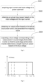
- Fig. 3 is a schematic flow diagram of a method for controlling a photovoltaic power generation system according to a embodiment of the present invention.
- An execution subject of the method may be the power optimizer as shown in Fig. 1 and Fig. 2 , as shown in Fig. 3 , the method include the following steps:
- a photovoltaic panel will generate voltage and current, which are transmitted to the power optimizer through a wire, and serve as input voltage Uin and input current lin of the power optimizer.
- step S303 obtaining the output power based on the actual input power and a pre-generated first mapping curve.
- the first mapping curve may be configured for indicating the corresponding relation between output voltage and the output power of the power optimizer, the first mapping curve may including: a first voltage segment linear power curve and a second voltage segment linear power curve, and the voltage corresponding to a second voltage segment is higher than the voltage corresponding to a first voltage segment.
- the maximum limit power of the power optimizer is denoted as Pomax.
- Fig. 4 is a schematic diagram of an external characteristic curve of output voltage and output power of a power optimizer in the related art; as shown in Fig. 4 , in the related art, the external characteristic curve of the output voltage Uo and the output power Po is a constant power curve from Vo1 to Vo4, the horizontal coordinate is the output voltage Uo of the power optimizer, and the vertical coordinate is the ratio of the output power Po of the power optimizer to the maximum limit power Pomax, that is, Po/Pomax.
- the phenomenon that the output power Po jumps from constant power to 0 may be caused, then the power optimizer enters into a cut-off area, the rear-stage photovoltaic inverter may not work normally, that is, the power optimizer and photovoltaic inverter have mismatch shocks.
- the invention proposes that the external characteristics of the relation curve of power and voltage of high and low voltage segments of the power optimizer are adjusted, so that the phenomenon that in response to the first MPPT unit in the power optimizer disturbs nears Vo1(or Vo4), the output power Po of the power optimizer jumps from constant power to 0 is effectively avoided, the power optimizer automatically adapts to the disturbance voltage change of the "photovoltaic inverter" connected at the rear stage to effectively balance the competitive relation between the "power optimizer "and the "photovoltaic inverter", and avoid the mismatch shocks situation.
- the power optimizer may obtain output power of the power optimizer based on the relation between the actual input power and the pre-generated first mapping curve.
- step S304 bus voltage corresponding to the output power is output to a rear-stage photovoltaic inverter so that the rear-stage photovoltaic inverter determines the target maximum power according to the bus voltage.
- the bus voltage corresponding to the output power refers to the output voltage Uo corresponding to the output power Po of the power optimizer.
- the power optimizer outputs output voltage Uo corresponding to the output power Po to a post-stage photovoltaic inverter so that a second MPPT unit in the post-stage photovoltaic inverter disturbs the bus voltage to obtain the target maximum power of the photovoltaic power generation system.
- the embodiments of the invention provide a method for controlling a photovoltaic power generation system, the method includes: input current and input voltage of a power optimizer are acquired; actual input power is obtained according to the input voltage and the input current; output power is obtained according to the actual input power and a pre-generated first mapping curve; the first mapping curve is configured for indicating the corresponding relation between output voltage and the output power of the power optimizer, the first mapping curve includes: a first voltage segment linear power curve and a second voltage segment linear power curve, and the voltage corresponding to a second voltage segment is higher than that corresponding to a first voltage segment; bus voltage corresponding to the output power is output to a post-stage photovoltaic inverter so that the post-stage photovoltaic inverter determines the target maximum power according to the bus voltage.
- the external characteristics of the relation curve of power and voltage of high and low voltage segments of the power optimizer are adjusted, so that in response to the first MPPT unit carries out disturbance near Vo1(or Vo4), output power may be obtained according to the actual input power and the pre-generated first mapping curve, and bus voltage corresponding to the output power is output to the post-stage photovoltaic inverter in order to enable the post-stage photovoltaic inverter to disturb the bus voltage to obtain the target maximum power of photovoltaic power generation system, the phenomenon that in response to the first MPPT unit in the power optimizer carries out disturbance near Vo1 (or Vo4) , the output power Po of the power optimizer jumps from constant power to 0 is effectively avoided, the power optimizer may automatically adapt to the disturbance voltage change of the "photovoltaic inverter" connected at the rear stage, so as to effectively balance the competitive relation between the "power optimizer "and the "photovoltaic inverter", and avoid the mismatch shock situation.
- the method may further include the following operations.
- the corresponding relations between the first voltage segment and the second voltage segment and the output power are respectively adjusted to obtain the first mapping curve, so that the power optimizer may obtain the output power according to the actual input power and the pre-generated voltage-power first mapping curve, the purpose of balancing the competitive relation between the "power optimizer” and the "photovoltaic inverter” is achieved, and mismatch shock situation is avoided.
- Fig. 5 is a schematic diagram of an external characteristic curve of output voltage and output power of a power optimizer provided by embodiments of the invention; as shown in Fig. 5 , the first mapping curve may further include: a third voltage segment constant power segment, and the voltage corresponding to a third voltage segment may be higher than that corresponding to the first voltage segment and lower than that corresponding to the second voltage segment.
- the first voltage segment linear power curve may be a linear curve in which power increases with increase of voltage or power decreases with decrease of voltage
- the second voltage segment linear power curve may be a linear curve in which power decreases with increase of voltage or power increases with decrease of voltage.
- the first voltage segment may be Vo1 to Vo2
- the relation between the output power Po and output voltage Uo of the power optimizer may be a positive correlation linear curve, that is, the output power Po of the power optimizer decreases with the decrease of output voltage Uo, it also can be understood as, the output power Po of the power optimizer increases with the increase of output voltage Uo.
- the output voltage Uo detected by the power optimizer is within the first voltage segment Vo1 to Vo2
- the bus voltage currently disturbed by the second MPPT unit in the photovoltaic optimizer is within the first voltage segment Vo1 to Vo2.
- the output power Po of the power optimizer decreases with the decrease of the output voltage Uo, that is, it can be determined that the current disturbance direction is wrong, the next cycle disturbs in the reverse direction, after several disturbances and observation, the tracking for the maximum output power point of the power optimizer may be realized.
- the second voltage segment may be Vo3 to Vo4, in the second voltage segment, the relation between the output power Po and output voltage Uo of the power optimizer may be a negative correlation linear curve, that is, the output power Po of the power optimizer decreases with the increase of output voltage Uo, it also can be understood as, the output power Po of the power optimizer increases with the decrease of output voltage Uo.
- the output voltage Uo detected by the power optimizer is within the second voltage segment Vo3 to Vo4
- the bus voltage currently disturbed by the second MPPT unit in the photovoltaic optimizer is within the second voltage segment Vo3 to V04.
- the output power Po of the power optimizer decreases with the increase of the output voltage Uo, that is, it can be determined that the current disturbance direction is wrong, the next cycle disturbs in the reverse direction, after several disturbances and observation, the tracking for the maximum output power point of the power optimizer may be realized.
- the situation that in the process of disturbance of the first MPPT unit in the power optimizer, the output power Po jumps to 0 may be avoided, and in response to the output voltage Uo exceeds the output voltage range, a protection or voltage limit control mechanism of the power optimizer may be triggered.
- the third voltage segment may be Vo2 to Vo3, the third voltage segment is a constant power curve, that is, the output power Po of the power optimizer is constant with the increase (or decrease) of the output voltage Uo, and the output power Po of the power optimizer is a constant value.
- the output power Po of the power optimizer is constant with the increase of the output voltage Uo, that is, the output power of the power optimizer may be determined according to the constant power of the third voltage segment and the actual input power of the power optimizer.
- Vo1 and Vo4 need to be included in the input range of the bus voltage (DC+, DC-) of the post-stage photovoltaic inverter, otherwise the normal operation of the post-stage photovoltaic inverter will be affected.
- the specific values of Vo1 and Vo4 maybe determined according to the input range of the common photovoltaic inverter, it is recommended that they may meet the requirements of the input range of most photovoltaic inverters.
- the slope of the first voltage segment linear power curve and the second voltage segment linear power curve should not be set too steep to avoid shock.
- S303, output power is obtained according to the actual input power and a pre-generated first mapping curve may include the following operations.
- output power may be obtained according to the first voltage segment linear power curve or the second voltage segment linear power curve.
- output power may be obtained according to the second voltage segment constant power curve
- the actual maximum photovoltaic input power is less than the maximum constant power value of the power optimizer, such as k less than 1, the actual working area is the area below the intersection of the dotted line of the k value and the external characteristics. Since the k value inevitably intersects with the first voltage segment constant power curve or the second voltage segment constant power curve, there is a maximum power interval.
- the power optimizer enters the high voltage and low voltage limit power segment, that is, the output power Po of the power optimizer may be obtained according to the first voltage segment linear power curve or the second voltage segment linear power curve, and the output power Po of the power optimizer is limited.
- S303, output power is obtained according to the actual input power and a pre-generated first mapping curve may further include the following operations.
- output power may be obtained according to the third voltage segment constant power segment.
- the actual input power Pin is less than or equal to the maximum limit power Pomax of the power optimizer, the actual input power is used as the output power.
- the maximum limit power is as the output power.
- the actual output power of the photovoltaic panels may be greater than or less than the maximum limit power Pomax of the power optimizer, if the output power of the photovoltaic panels is greater than or equal to the maximum limit power Pomax of the power optimizer, the output power Po of the power optimizer is equal to the maximum limit power Pomax; if the maximum output capacity of the photovoltaic panels is less than the maximum limit power Pomax of the power optimizer (ratio is less than 1), the output power Po of the power optimizer is equal to the maximum power of the photovoltaic panel, and the maximum power of the photovoltaic panel may be tracked through the first MPPT unit in the power optimizer.
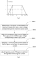
- Fig. 6 is a schematic flow diagram of another method for controlling a photovoltaic power generation system provided by embodiments of the invention; optionally, as shown in Fig. 6 , in the above S303, the operation after output power is obtained according to the actual input power and a pre-generated first mapping curve may further include the following operations.
- step S601 a first given current is determined based on MPP and given voltage corresponding to the MPP.
- the MPP is obtained by the disturbance of the MPP unit in the power optimizer based on input voltage and input current.
- the MPP unit may also be understood as the first MPPT unit disposed in the power optimizer, the input voltage and input current of the power optimizer are the voltage and current generated by the photovoltaic panel.
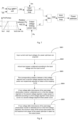
- Fig. 7 is a schematic diagram of working principle of an MPPT unit and an output voltage limiting power loop in a power optimizer in a method for controlling a photovoltaic power generation system provided by embodiments of the invention.
- the first MPPT unit perturbs the voltage and current generated by the photovoltaic panel, and tracks the maximum power point of the photovoltaic panel and the given voltage Vin* corresponding to the maximum power point, and transmits the given voltage Vin* to an input voltage inner loop, so that the first given current I1* may be determined according to the given voltage Vin*.
- step S602 a second given current is determined based on the output power and output voltage corresponding to the output power.
- the output power Po corresponding to the output voltage Uo is obtained based on the relation curve between the output power Po of the power optimizer and the output voltage Uo, and the second given current I2* is calculated from an output voltage limiting power loop.
- step S603 a minimum given current is obtained based on the first given current and the second given current.
- step S604 a duty cycle of the power optimizer is adjusted through the minimum given current.
- the first given current I1* and the second given current I2* are compared, the minimum value of the first given current I1* and the second given current I2* is taken as the minimum given current Imin*, and the minimum given current Imin* is transferred to an inner current loop as the reference given.
- the power optimizer is further provided with an MOSFET, so a current loop controller may use the minimum given current to achieve the change of duty cycle D of the MOSFET, thus generating disturbance of current and achieving the purpose of stabilizing the output voltage.
- Fig. 8 is a schematic diagram of an overall process of a method for controlling a photovoltaic power generation system provided by embodiments of the invention.
- the method include the following steps:
- Fig. 9 is a schematic structure diagram of an apparatus for controlling a photovoltaic power generation system provided by embodiments of the invention.
- the apparatus for controlling a photovoltaic power generation system include: an acquisition module 901, a processing module 902 and a determination module 903.
- the acquisition module 901 may be configured to acquire input current and input voltage of a power optimizer.
- the processing module 902 may be configured to obtain actual input power according to the input voltage and the input current, and obtain output power according to the actual input power and a pre-generated first mapping curve; the first mapping curve is configured for indicating the corresponding relation between output voltage and the output power of the power optimizer, the first mapping curve include: a first voltage segment linear power curve and a second voltage segment linear power curve, and the voltage corresponding to a second voltage segment is higher than that corresponding to a first voltage segment.
- the determination module 903 may be configured to output bus voltage corresponding to the output power to a post-stage photovoltaic inverter so that the post-stage photovoltaic inverter determines the target maximum power according to the bus voltage.
- the first mapping curve may further include: a third voltage segment constant power segment, and the voltage corresponding to a third voltage segment may be higher than the voltage corresponding to the first voltage segment and lower than the voltage corresponding to the second voltage segment.
- the first voltage segment linear power curve may be a linear curve in which power increases with increase of voltage
- the second voltage segment linear power curve may be a linear curve in which power decreases with increase of voltage
- processing module 902 may be further configured to: in response to the bus voltage after disturbance of the post-stage photovoltaic inverter being detected and being in the first voltage segment or the second voltage segment, output power may be obtained according to the first voltage segment linear power curve or the second voltage segment linear power curve.
- processing module 902 may be further configured to: in response to bus voltage after disturbance of the post-stage photovoltaic inverter being detected and being in the third voltage segment, output power may be obtained according to the third voltage segment constant power segment.
- the processing module 902 may be further configured to: in response to the actual input power being less than or equal to the maximum limit power of the power optimizer, the actual input power may be taken as the output power.
- the processing module 902 may be further configured to: in response to the actual input power being greater than the maximum limit power, the maximum limit power may be taken as the output power.
- the apparatus further includes an adjusting module.
- the adjusting module may be configured to adjust corresponding relations between the first voltage segment and the second voltage segment and the output power respectively to obtain the first mapping curve.
- the adjusting module may be further configured to:
- the processing module 902 may be further configured to: determine a first given current according to an MPP and a given voltage corresponding to the MPP; the MPP is an MPP unit in the power optimizer and is obtained by carrying out disturbance according to input voltage and input current; determine a second given current according to the output power and output voltage corresponding to the output power; and obtain a minimum given current according to the first given current and the second given current.
- the apparatus may further include: an adjusting module, the adjusting module may be configured to adjust a duty cycle of the power optimizer by using the minimum given current.
- the above modules may be at least one integrated circuits configured to implement the above method, for example, at least one Application Specific Integrated Circuits (ASICs), or at least one Digital Signal Processors (DSPs), or at least one Field Programmable Gate Arrays (FPGAs), etc.
- ASICs Application Specific Integrated Circuits
- DSPs Digital Signal Processors
- FPGAs Field Programmable Gate Arrays
- the processing element may be a general-purpose processor, such as a Central Processing Unit (CPU) or another processor that can call the program code.
- CPU Central Processing Unit
- these modules may be integrated together and implemented in the form of a System-on-a-Chip (SOC).
- SOC System-on-a-Chip
- the invention further provides a program product, such as a computer-readable storage medium.
- the program product may include a program, and in response to executed by a processor, the program is used to execute the above method embodiments.
- the disclosed apparatus and method may be implemented in other manners.
- the apparatus embodiments described above are only schematic.
- division of the units is only logic function division, and other division manners may be adopted during practical implementation.
- multiple units or components may be combined or integrated into another system, or some characteristics may be neglected or not executed.
- coupling or direct coupling or communication connection between each displayed or discussed component may be indirect coupling or communication connection, implemented through some interfaces, of the device or the units, and may be electrical and mechanical or adopt other forms.
- the units described as separate parts may or may not be physically separated, and parts displayed as units may or may not be physical units, namely they may be located in the same place, or may be distributed to multiple network units. Part or all of the units may be selected to achieve the purposes of the solutions of the embodiments according to a practical requirement.
- each function unit in each embodiment of the invention may be integrated into a processing unit, or each unit may exist independently, or two or more than two units may also be integrated into a unit.
- the integrated unit may be implemented in a hardware form and may also be implemented in form of hardware and software functional unit.
- the integrated unit realized in form of software functional unit may be stored in a computer-readable storage medium.
- the above-mentioned software functional unit is stored in a storage medium, and includes a plurality of instructions to enable a computer device (which may be a personal computer, a server, or a network device, etc.) or a processor to execute some steps of the method described in various embodiments of the invention.
- the above-mentioned storage medium includes: any medium that can store program code, such as a USB flash drive, a removable hard disk, a Read - Only Memory (ROM), a Random Access Memory (RAM), a magnetic disk, or an optical disc.
- the invention provides a method and apparatus for controlling photovoltaic power generation system, a power optimizer, and a storage medium.
- the method includes: input current and input voltage of a power optimizer are acquired; actual input power is obtained based on the input voltage and the input current; output power is obtained based on the actual input power and a pre-generated first mapping curve; the first mapping curve is configured for indicating the corresponding relation between output voltage and the output power of the power optimizer, the first mapping curve includes: a first voltage segment linear power curve and a second voltage segment linear power curve, and the voltage corresponding to a second voltage segment is higher than the voltage corresponding to a first voltage segment; bus voltage corresponding to the output power is output to a post-stage photovoltaic inverter so that the post-stage photovoltaic inverter determines the target maximum power according to the bus voltage.
- the method and apparatus for controlling the photovoltaic power generation system, the power optimizer, and the storage medium reproducible and may be used in a variety of industrial applications.
- the method and apparatus for controlling the photovoltaic power generation system, the power optimizer, and the storage medium may be used in the technical filed of power electronics.
Landscapes
- Engineering & Computer Science (AREA)
- Power Engineering (AREA)
- Physics & Mathematics (AREA)
- Microelectronics & Electronic Packaging (AREA)
- Electromagnetism (AREA)
- General Physics & Mathematics (AREA)
- Radar, Positioning & Navigation (AREA)
- Automation & Control Theory (AREA)
- Nonlinear Science (AREA)
- Sustainable Development (AREA)
- Sustainable Energy (AREA)
- Life Sciences & Earth Sciences (AREA)
- Control Of Electrical Variables (AREA)
Applications Claiming Priority (2)
| Application Number | Priority Date | Filing Date | Title |
|---|---|---|---|
| CN202110710849.8A CN113452071B (zh) | 2021-06-25 | 2021-06-25 | 光伏发电系统控制方法、装置、功率优化器及存储介质 |
| PCT/CN2021/141371 WO2022267409A1 (fr) | 2021-06-25 | 2021-12-24 | Procédé et appareil de commande de système de production d'énergie photovoltaïque, optimiseur de puissance et support de stockage |
Publications (2)
| Publication Number | Publication Date |
|---|---|
| EP4231480A1 true EP4231480A1 (fr) | 2023-08-23 |
| EP4231480A4 EP4231480A4 (fr) | 2024-11-13 |
Family
ID=77812834
Family Applications (1)
| Application Number | Title | Priority Date | Filing Date |
|---|---|---|---|
| EP21946882.4A Pending EP4231480A4 (fr) | 2021-06-25 | 2021-12-24 | Procédé et appareil de commande de système de production d'énergie photovoltaïque, optimiseur de puissance et support de stockage |
Country Status (3)
| Country | Link |
|---|---|
| EP (1) | EP4231480A4 (fr) |
| CN (1) | CN113452071B (fr) |
| WO (1) | WO2022267409A1 (fr) |
Cited By (1)
| Publication number | Priority date | Publication date | Assignee | Title |
|---|---|---|---|---|
| CN120016827A (zh) * | 2024-06-28 | 2025-05-16 | 深圳市正浩智造科技有限公司 | 直流变换器的放电控制方法、功率变换设备及储能设备 |
Families Citing this family (3)
| Publication number | Priority date | Publication date | Assignee | Title |
|---|---|---|---|---|
| CN113452071B (zh) * | 2021-06-25 | 2024-12-13 | 江苏领充创享新能源科技有限公司 | 光伏发电系统控制方法、装置、功率优化器及存储介质 |
| CN114583682A (zh) * | 2022-03-08 | 2022-06-03 | 阳光氢能科技有限公司 | 一种光伏直流离网制氢系统及其控制方法 |
| CN119045589B (zh) * | 2024-10-31 | 2025-02-11 | 锦浪科技股份有限公司 | 一种光伏优化器输出电压自适应限幅控制方法 |
Family Cites Families (9)
| Publication number | Priority date | Publication date | Assignee | Title |
|---|---|---|---|---|
| CN102237823A (zh) * | 2010-12-30 | 2011-11-09 | 保定天威集团有限公司 | 一种光伏功率优化器 |
| CN106787707B (zh) * | 2017-02-24 | 2020-05-22 | 上海交通大学 | 内嵌储能型多模块串联式光伏直流升压变换器及应用方法 |
| CN107154780B (zh) * | 2017-06-08 | 2019-04-09 | 阳光电源股份有限公司 | 一种光伏发电系统及其功率控制方法与功率优化器 |
| CN108448621B (zh) * | 2018-04-08 | 2021-01-08 | 阳光电源股份有限公司 | 一种光伏发电系统的控制方法及设备 |
| CN109254616B (zh) * | 2018-10-10 | 2020-07-07 | 阳光电源股份有限公司 | 一种输入功率控制方法以及光伏逆变器 |
| CN109713714B (zh) * | 2018-11-15 | 2020-12-25 | 华为技术有限公司 | 一种最大功率点跟踪方法及设备 |
| WO2020133056A1 (fr) * | 2018-12-27 | 2020-07-02 | Abb Schweiz Ag | Centrale électrique photovoltaïque centrale et répartie et son système de commande |
| CN109787289B (zh) * | 2019-03-15 | 2021-08-13 | 矽力杰半导体技术(杭州)有限公司 | 功率变换系统、光伏优化器及功率跟踪方法 |
| CN113452071B (zh) * | 2021-06-25 | 2024-12-13 | 江苏领充创享新能源科技有限公司 | 光伏发电系统控制方法、装置、功率优化器及存储介质 |
-
2021
- 2021-06-25 CN CN202110710849.8A patent/CN113452071B/zh active Active
- 2021-12-24 WO PCT/CN2021/141371 patent/WO2022267409A1/fr not_active Ceased
- 2021-12-24 EP EP21946882.4A patent/EP4231480A4/fr active Pending
Cited By (1)
| Publication number | Priority date | Publication date | Assignee | Title |
|---|---|---|---|---|
| CN120016827A (zh) * | 2024-06-28 | 2025-05-16 | 深圳市正浩智造科技有限公司 | 直流变换器的放电控制方法、功率变换设备及储能设备 |
Also Published As
| Publication number | Publication date |
|---|---|
| CN113452071B (zh) | 2024-12-13 |
| WO2022267409A1 (fr) | 2022-12-29 |
| CN113452071A (zh) | 2021-09-28 |
| EP4231480A4 (fr) | 2024-11-13 |
Similar Documents
| Publication | Publication Date | Title |
|---|---|---|
| EP4231480A1 (fr) | Procédé et appareil de commande de système de production d'énergie photovoltaïque, optimiseur de puissance et support de stockage | |
| US20230261510A1 (en) | Method and apparatus for controlling busbar voltage of photovoltaic system | |
| US10411479B2 (en) | Detection circuit and detection method for detecting insulation resistance of photovoltaic inverter, and photovoltaic inverter | |
| US10505437B2 (en) | Power converting device and ground impedance value detecting method | |
| EP3979492B1 (fr) | Procédé de commande de reflux d'énergie électrique, convertisseur et système de génération d'énergie photovoltaïque | |
| EP2993754A1 (fr) | Procédé de sortie et de commutation de conversion optimale d'énergie centralisé et son application | |
| CN105680797B (zh) | 一种检测光伏组串的电流电压曲线的方法及系统 | |
| US12184055B2 (en) | Arc detection device, solar inverter, indoor wiring system, breaker, solar panel, solar panel- attached module, and junction box | |
| US11888321B2 (en) | Power conversion apparatus and method for controlling output impedance of power conversion apparatus | |
| US20220085758A1 (en) | Detection condition determining method, apparatus, and photovoltaic system | |
| JPWO2018087813A1 (ja) | 系統連系インバータ装置 | |
| WO2020142890A1 (fr) | Procédé destiné à régler la tension de bus, et dispositif associé | |
| US20170222440A1 (en) | Photovoltaic System | |
| EP3242183B1 (fr) | Procédé de commande de suivi du point de puissance maximale d'une cellule solaire, et dispositif de suivi | |
| EP4697543A1 (fr) | Onduleur de stockage d'énergie photovoltaïque et son procédé de commande | |
| US10411476B2 (en) | Power conversion apparatus, power conversion method, and power conversion system | |
| CN108183508B (zh) | 光伏逆变器在两路mppt输入条件下的控制方法 | |
| US20190386482A1 (en) | Alternating current optimal yield control within a multi-power stack inverter | |
| CN115993871B (zh) | 电流控制方法及光伏系统 | |
| CN116048182B (zh) | 光伏组件柔性功率点跟踪方法、装置、设备、介质及系统 | |
| CN117749086A (zh) | 一种拉弧的识别方法、逆变器及逆变系统 | |
| US12088080B2 (en) | Arc detection device, solar inverter, indoor wiring system, breaker, solar panel, solar panel-attached module, and junction box | |
| JP2025535855A (ja) | 充電制御方法、装置、ソーラー充電コントローラ及び記憶媒体 | |
| CN111130421B (zh) | 变频器控制方法 | |
| CN118367615A (zh) | 一种光伏发电并网控制方法及系统 |
Legal Events
| Date | Code | Title | Description |
|---|---|---|---|
| STAA | Information on the status of an ep patent application or granted ep patent |
Free format text: STATUS: THE INTERNATIONAL PUBLICATION HAS BEEN MADE |
|
| PUAI | Public reference made under article 153(3) epc to a published international application that has entered the european phase |
Free format text: ORIGINAL CODE: 0009012 |
|
| STAA | Information on the status of an ep patent application or granted ep patent |
Free format text: STATUS: REQUEST FOR EXAMINATION WAS MADE |
|
| 17P | Request for examination filed |
Effective date: 20230519 |
|
| AK | Designated contracting states |
Kind code of ref document: A1 Designated state(s): AL AT BE BG CH CY CZ DE DK EE ES FI FR GB GR HR HU IE IS IT LI LT LU LV MC MK MT NL NO PL PT RO RS SE SI SK SM TR |
|
| DAV | Request for validation of the european patent (deleted) | ||
| DAX | Request for extension of the european patent (deleted) | ||
| A4 | Supplementary search report drawn up and despatched |
Effective date: 20241011 |
|
| RIC1 | Information provided on ipc code assigned before grant |
Ipc: H02S 40/30 20140101ALI20241007BHEP Ipc: G05F 1/67 20060101ALI20241007BHEP Ipc: H02J 3/38 20060101AFI20241007BHEP |