EP4232137B1 - Anker für eine neuromodulationsleitung - Google Patents
Anker für eine neuromodulationsleitung Download PDFInfo
- Publication number
- EP4232137B1 EP4232137B1 EP21790924.1A EP21790924A EP4232137B1 EP 4232137 B1 EP4232137 B1 EP 4232137B1 EP 21790924 A EP21790924 A EP 21790924A EP 4232137 B1 EP4232137 B1 EP 4232137B1
- Authority
- EP
- European Patent Office
- Prior art keywords
- anchor
- lead
- fixing element
- opening
- anchor block
- Prior art date
- Legal status (The legal status is an assumption and is not a legal conclusion. Google has not performed a legal analysis and makes no representation as to the accuracy of the status listed.)
- Active
Links
Images


Classifications
-
- A—HUMAN NECESSITIES
- A61—MEDICAL OR VETERINARY SCIENCE; HYGIENE
- A61N—ELECTROTHERAPY; MAGNETOTHERAPY; RADIATION THERAPY; ULTRASOUND THERAPY
- A61N1/00—Electrotherapy; Circuits therefor
- A61N1/02—Details
- A61N1/04—Electrodes
- A61N1/05—Electrodes for implantation or insertion into the body, e.g. heart electrode
- A61N1/0551—Spinal or peripheral nerve electrodes
- A61N1/0558—Anchoring or fixation means therefor
-
- A—HUMAN NECESSITIES
- A61—MEDICAL OR VETERINARY SCIENCE; HYGIENE
- A61N—ELECTROTHERAPY; MAGNETOTHERAPY; RADIATION THERAPY; ULTRASOUND THERAPY
- A61N1/00—Electrotherapy; Circuits therefor
- A61N1/02—Details
- A61N1/04—Electrodes
- A61N1/05—Electrodes for implantation or insertion into the body, e.g. heart electrode
- A61N1/056—Transvascular endocardial electrode systems
- A61N1/057—Anchoring means; Means for fixing the head inside the heart
- A61N2001/0582—Suture sleeves
Definitions
- the present invention is generally directed to a lead anchor for a neuromodulation lead that can be used for spinal cord stimulation of a patient in order to relieve pain by electrically activating pain-inhibiting neurons in the posterior horn.
- a lead anchor may comprise a solid anchor block having at least one opening and a lumen configured to receive a portion of a neuromodulation lead. Further, the lead anchor is configured to fix the neuromodulation lead at the patient's body.
- the access to the tool mount of the screw is another drawback of the known lead anchor system.
- the screw is covered by flexible silicone.
- the tool mount may also be covered, so that due to the small size of the tool mount of the screw, usually M2 screws are used, and due to a relatively short tool engagement length, the application is quite complicated and user unfriendly.
- This is mainly due to the lack of visual feedback for the implanting physician to confirm that the torque wrench is fully engaged in the tool mount before applying torque to fix the lead by the fixing element.
- the lack of visual feedback leads to uncertainty and reduced confidence in the procedure, which increases the time required for implantation and potentially increases the risk for the patient.
- the anchor block is 'solid' means that the anchor block has an increased material stiffness compared to a soft material.
- 'solid' means that the anchor block has a higher material stiffness than the anchor body.
- the term 'solid' may be understood in relation to the configuration of the anchor block in that the anchor block is formed from a solid material or has a corresponding geometry that favors the stiffness of the anchor block compared to the anchor body.
- the anchor block has an essential cylindrical form and provides a stable core within the lead anchor in which the lead is effectively fixed.
- the anchor body provides protection of the anchor block and a comfortable seat of the lead anchor at the patient's body.
- the first stop feature of the fixing element with a dimension greater than a diameter of the opening ensures that the fixing element is limited in its movement along the longitudinal axis of the opening, e.g. during screwing in, by a contact surface of the opening located at its first end.
- the first end is opposite to its second end which forms the connection with the lumen of the anchor block.
- the fixing element comprises a first stop feature
- the fixing element during insertion abuts the anchor block at the first end of the opening thus limiting insertion.
- the inventive lead anchor prevents overtightening of the fixing element, e.g. the threaded screw, thereby avoiding over-compression of the lead and thereby damaging of the lead.
- the anchor body may comprise a passage, for example a cylindrical passage, which is in line with the lumen of the anchor block.
- the passage of the anchor body and the lumen of the anchor block may form together a lead-through for a respective neuromodulation lead.
- the head portion comprises at least one second stop feature, wherein said stop feature limits the movement of the fixing element against the direction of insertion.
- the movement may be limited by abutting of the second stop feature against the anchor body.
- the fact that the movement of the fixing element is limited means that the second stop feature of the fixing element can only be moved against the direction of insertion up to a predefined maximum length along the longitudinal axis of the opening.
- the fixing element may be moved further against the direction of insertion but then, however, destroys the anchor body.
- the second stop feature may also be realized by a flange-like projection or a screw head (cap), for example the same projection or head which forms the first stop feature.
- the second stop feature of the head portion of the fixing element may be formed by one or more projections that extends radially from the fastening portion or head.
- the second stop feature may be, for example, provided by a flange surface arranged at the side of the projection or head pointing away from the fastening portion (i.e. a flange surface of the projection or head that faces away from the fastening portion).
- the limitation in the movement of the second stop feature may be provided by a flange-like face or step face at an opening within the anchor body, wherein the opening allows access to the head portion of the fixing element for tightening.
- the first stop feature and the second stop feature may extend partly or fully around the head portion of the fixing element.
- Fig. 1 to 5 show a lead anchor 100 for a neuromodulation lead comprising an anchor block 5, an anchor body 4 and a fixing element 10, wherein the anchor body 4 covers or surrounds the anchor block 5.
- the fixing element 10 comprises a hexagon socket as a tool mount 1.
- Fig. 1 shows a top view of the lead anchor, only a head portion 2 of the fixing element 10 is shown.
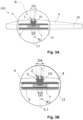
- the axis marked with the arrows and letters 'A' represents the cutting axis for the longitudinal sectional views in Figs. 3A and 3B .
- the axis extends along the longitudinal extension of the lead anchor 100.
- Fig. 3A shows that the anchor body 4 comprises a passage 20 which is formed as a cylindrical passage, extending along the cutting axis.
- the passage 20 is in line with a cylindrical lumen 6 of the anchor block 5 and thereby forming a lead-through for a neuromodulation lead.
- the lumen 6 as well as the passage 20 are best seen in the longitudinal sectional views of Figs. 3A and 3B .
- the lower surface 18 of the fixing element 10 As the diameter D4 of the lower surface 18 of the fixing element 10 is greater than the diameter D1 of the opening 9, the lower surface 18 abuts to the contact surface 12 of the opening 9 when the fixing element 10 is inserted into the opening thereby limiting its movement into the direction of lumen 6.
- a lead anchor 100 of a second embodiment is shown in a top view, with the anchor body 4 being partially transparent, so that the anchor block 5 is visible inside the anchor body 4.
- Fig. 5 has four rows of projections 13, wherein each two rows are located at the right and left end section of anchor block 5 in longitudinal direction.
- the lead anchor 100 shows six projections 13 per side.
- the pin-like projections project perpendicularly from the outer surface of the anchor block 5 and protrude through the anchor body 4 so that they are accessible from the outside.
- one row of projections may be provided at each end section.
- the lead anchor shown in Fig. 5 comprises four rings 14, one ring 14 per row of projections 13. Alternatively, there can be more or less projections 13 and correspondingly more or less rings 14.
- the projections 13 help a physician to suture the lead anchor 100 in the patient's body, for example in his or her fascia.
- the suturing material can be guided around the projections 13 in a suitable manner, so that the lead anchor 100 can be held in place. Further, the suturing material may be guided through the rings 14.
- the rings 14 may prevent the suturing material from slipping axially in the longitudinal direction of the lead anchor 100.
Landscapes
- Health & Medical Sciences (AREA)
- Neurology (AREA)
- Neurosurgery (AREA)
- Orthopedic Medicine & Surgery (AREA)
- Cardiology (AREA)
- Heart & Thoracic Surgery (AREA)
- Engineering & Computer Science (AREA)
- Biomedical Technology (AREA)
- Nuclear Medicine, Radiotherapy & Molecular Imaging (AREA)
- Radiology & Medical Imaging (AREA)
- Life Sciences & Earth Sciences (AREA)
- Animal Behavior & Ethology (AREA)
- General Health & Medical Sciences (AREA)
- Public Health (AREA)
- Veterinary Medicine (AREA)
- Surgical Instruments (AREA)
- Prostheses (AREA)
Claims (12)
- Elektrodenverankerung (100) für eine Neuromodulationselektrodenleitung, umfassend:einen festen Ankerblock (5) mit einem Lumen (6) und mindestens einer Öffnung (9), wobei das Lumen (6) dazu eingerichtet ist, einen Abschnitt der Neuromodulationselektrodenleitung aufzunehmen, und wobei die Öffnung (9) mit dem Lumen (6) verbunden ist und eine Längsachse (L1) aufweist;einen Ankerkörper (4), der den Ankerblock (5) zumindest zum Teil bedeckt; undein Fixierelement (10), das einen Befestigungsabschnitt (16) und einen Kopfabschnitt (2) aufweist, wobei der Befestigungsabschnitt (16) dazu eingerichtet ist, entlang der Achse (L1) in die Öffnung (9) eingeführt zu werden, um den Abschnitt der Neuromodulationselektrodenleitung zu fixieren, wobei der Kopfabschnitt (2) mindestens ein erstes Anschlagmerkmal (18) aufweist, das in einer in Bezug auf die Achse (L1) radialen Richtung (R1) eine Abmessung (D4) aufweist, die größer ist als ein Durchmesser (D1) der Öffnung (9);dadurch gekennzeichnet, dassder Ankerblock (5) mindestens einen Vorsprung (13) oder mindestens eine Durchführung (11) umfasst, der bzw. die von dem Ankerblock (5) vorsteht,wobei der mindestens eine Vorsprung (13) oder die mindestens eine Durchführung (11) von dem Ankerkörper (4) vorsteht und durch den Ankerkörper (4) hindurch geht.
- Elektrodenverankerung (100) nach Anspruch 1, wobei der Kopfabschnitt (2) mindestens ein zweites Anschlagmerkmal (17) umfasst, wobei das Anschlagmerkmal (17) die Bewegung des Fixierelements (10) entgegen der Einführrichtung begrenzt.
- Elektrodenverankerung (100) nach Anspruch 2, wobei das mindestens eine erste Anschlagmerkmal (18) und das mindestens eine zweite Anschlagmerkmal (17) des Fixierelements (10) entlang des longitudinalen Verlaufs des Fixierelements (10) entlang der Achse (L1) versetzt sind.
- Elektrodenverankerung (100) nach einem der vorangehenden Ansprüche, wobei der Abschnitt der Neuromodulationselektrodenleitung zumindest zum Teil innerhalb einer Hülse (7), beispielsweise eines Gitters, angeordnet ist.
- Elektrodenverankerung (100) nach Anspruch 4, wobei die Hülse (7) dauerhaft innerhalb des Lumens (6) des Ankerblocks (5) befestigt, zum Beispiel angeschweißt, ist.
- Elektrodenverankerung (100) nach Anspruch 4, wobei der Ankerblock (5) mindestens eine Kappe (15) umfasst, die an einem Ende des Lumens (6) angeordnet und dazu eingerichtet ist, die Hülse (7) zu sichern.
- Elektrodenverankerung (100) nach einem der vorangehenden Ansprüche, mindestens zwei Durchführungen (11) umfassend, wobei die Durchführungen (11) versetzt angeordnet sind.
- Elektrodenverankerung (100) nach einem der vorangehenden Ansprüche, wobei der Ankerblock (5) mindestens einen Vorsprung (13) umfasst, wobei beim Nähen der Elektrodenverankerung (100) Nähmaterial zumindest zum Teil um den mindestens einen Vorsprung (13) herum positioniert wird.
- Elektrodenverankerung (100) nach einem der vorangehenden Ansprüche, wobei der Ankerblock (5) ein Metall- und/oder ein Polymermaterial umfasst.
- Elektrodenverankerung (100) nach einem der vorangehenden Ansprüche, wobei der Ankerblock (4) Polymermaterial, zum Beispiel Silikon, umfasst.
- Elektrodenverankerung (100) nach einem der vorangehenden Ansprüche, wobei der Kopfabschnitt (2) des Fixierelements (10) eine Werkzeugaufnahme (1) umfasst.
- Verfahren zum Herstellen der Elektrodenverankerung (100) nach einem der vorangehenden Ansprüche, wobei das Verfahren die folgenden Schritte umfasst:• Bereitstellen des Ankerblocks (5) mit der mindestens einen Öffnung (9);• Einführen des Fixierelements (10) mit seinem Befestigungsabschnitt (16) in die Öffnung (9); und• Ausbilden des Ankerblocks (5) durch Umspritzung, wobei zumindest der Kopfabschnitt (2) des Fixierelements (10) teilweise frei gelassen wird, um dadurch den Ankerkörper (4) zu erzeugen.
Applications Claiming Priority (3)
| Application Number | Priority Date | Filing Date | Title |
|---|---|---|---|
| US202063104074P | 2020-10-22 | 2020-10-22 | |
| EP21158027 | 2021-02-19 | ||
| PCT/EP2021/078591 WO2022084177A1 (en) | 2020-10-22 | 2021-10-15 | Lead anchor for a neuromodulation lead |
Publications (2)
| Publication Number | Publication Date |
|---|---|
| EP4232137A1 EP4232137A1 (de) | 2023-08-30 |
| EP4232137B1 true EP4232137B1 (de) | 2025-07-02 |
Family
ID=78134998
Family Applications (1)
| Application Number | Title | Priority Date | Filing Date |
|---|---|---|---|
| EP21790924.1A Active EP4232137B1 (de) | 2020-10-22 | 2021-10-15 | Anker für eine neuromodulationsleitung |
Country Status (3)
| Country | Link |
|---|---|
| US (1) | US20230390550A1 (de) |
| EP (1) | EP4232137B1 (de) |
| WO (1) | WO2022084177A1 (de) |
Citations (3)
| Publication number | Priority date | Publication date | Assignee | Title |
|---|---|---|---|---|
| US20100274336A1 (en) * | 2009-04-27 | 2010-10-28 | Boston Scientific Neuromodulation Corporation | Torque lock anchor and methods and devices using the anchor |
| EP2902074A1 (de) * | 2014-01-29 | 2015-08-05 | BIOTRONIK SE & Co. KG | Elektrodenfixierhülse mit versteiftem befestigungsabschnitt und verfahren zu deren herstellung |
| EP3511050A1 (de) * | 2018-01-11 | 2019-07-17 | Heraeus Medical Components LLC | Fadenanker und nähvorrichtung |
Family Cites Families (5)
| Publication number | Priority date | Publication date | Assignee | Title |
|---|---|---|---|---|
| EP2790773B1 (de) * | 2012-01-25 | 2020-10-14 | Nevro Corporation | Leiteranker |
| CN105451807A (zh) * | 2013-08-07 | 2016-03-30 | 波士顿科学神经调制公司 | 制造与使用用于电刺激系统的引导件的引导件锚定件的系统与方法 |
| US9095701B2 (en) * | 2013-08-30 | 2015-08-04 | Boston Scientific Neuromodulation Corporation | Systems and methods for making and using lead anchors for leads of electrical stimulation systems |
| WO2017151438A1 (en) * | 2016-02-29 | 2017-09-08 | Boston Scientific Neuromodulation Corporation | Lead anchor for an electrical stimulation system |
| US11565105B2 (en) * | 2018-10-05 | 2023-01-31 | Biotronik Se & Co. Kg | Lead anchor for a neuromodulation lead |
-
2021
- 2021-10-15 EP EP21790924.1A patent/EP4232137B1/de active Active
- 2021-10-15 US US18/032,685 patent/US20230390550A1/en active Pending
- 2021-10-15 WO PCT/EP2021/078591 patent/WO2022084177A1/en not_active Ceased
Patent Citations (3)
| Publication number | Priority date | Publication date | Assignee | Title |
|---|---|---|---|---|
| US20100274336A1 (en) * | 2009-04-27 | 2010-10-28 | Boston Scientific Neuromodulation Corporation | Torque lock anchor and methods and devices using the anchor |
| EP2902074A1 (de) * | 2014-01-29 | 2015-08-05 | BIOTRONIK SE & Co. KG | Elektrodenfixierhülse mit versteiftem befestigungsabschnitt und verfahren zu deren herstellung |
| EP3511050A1 (de) * | 2018-01-11 | 2019-07-17 | Heraeus Medical Components LLC | Fadenanker und nähvorrichtung |
Also Published As
| Publication number | Publication date |
|---|---|
| WO2022084177A1 (en) | 2022-04-28 |
| EP4232137A1 (de) | 2023-08-30 |
| US20230390550A1 (en) | 2023-12-07 |
Similar Documents
| Publication | Publication Date | Title |
|---|---|---|
| AU2002249391C1 (en) | Implant | |
| US5125840A (en) | Enossal single tooth implant with twisting restraint | |
| EP1048318B1 (de) | Positionier- und Verankerungssystem für eine medizinische Leitung | |
| ES2829585T3 (es) | Anclajes de cables y sistemas y métodos asociados | |
| JP3680358B2 (ja) | スペース保持部材として脊柱の椎体間に装入する生体埋め込み部材 | |
| EP1790310B1 (de) | Orthodontische Knochenschraube | |
| US6482182B1 (en) | Anchoring system for a brain lead | |
| ES2576358T3 (es) | Tornillo óseo | |
| US5746722A (en) | Suture sleeve with circumferential lead locking device | |
| US20060127158A1 (en) | Implantable electrical lead retention system and method | |
| ES2893225T3 (es) | Conjuntos de contacto para dispositivos médicos para su uso en cables implantables | |
| US6148237A (en) | Cardiac pacemaker lead with swaged distal electrode | |
| US20170028207A1 (en) | Leadless cardiac pacemaker with delivery and/or retrieval features | |
| US9555236B2 (en) | Implantable capsule for leadless cardiac pacing | |
| US20070078399A1 (en) | Medical device anchor and method of manufacture thereof | |
| US20080195178A1 (en) | Fixation methods and systems for cochlear implant component or other implantable devices | |
| KR101953301B1 (ko) | 임플란트 구조체 및 어버트먼트 | |
| EP3033144B1 (de) | Leitungsloser herzschrittmacher mit abgabe- und/oder entnahmefunktion | |
| EP4232137B1 (de) | Anker für eine neuromodulationsleitung | |
| JP6639286B2 (ja) | 貫通固定される多数の義歯 | |
| US12599762B2 (en) | Lead anchor for a neuromodulation lead | |
| WO2024074299A1 (en) | Header assembly for an implantable intracardiac device and respective intracardiac device | |
| KR102208556B1 (ko) | 임플란트 구조체 및 어버트먼트 | |
| CN114073815B (zh) | 电极密封装置 | |
| KR20190041051A (ko) | 임플란트용 픽스쳐 |
Legal Events
| Date | Code | Title | Description |
|---|---|---|---|
| STAA | Information on the status of an ep patent application or granted ep patent |
Free format text: STATUS: UNKNOWN |
|
| STAA | Information on the status of an ep patent application or granted ep patent |
Free format text: STATUS: THE INTERNATIONAL PUBLICATION HAS BEEN MADE |
|
| PUAI | Public reference made under article 153(3) epc to a published international application that has entered the european phase |
Free format text: ORIGINAL CODE: 0009012 |
|
| STAA | Information on the status of an ep patent application or granted ep patent |
Free format text: STATUS: REQUEST FOR EXAMINATION WAS MADE |
|
| 17P | Request for examination filed |
Effective date: 20230414 |
|
| AK | Designated contracting states |
Kind code of ref document: A1 Designated state(s): AL AT BE BG CH CY CZ DE DK EE ES FI FR GB GR HR HU IE IS IT LI LT LU LV MC MK MT NL NO PL PT RO RS SE SI SK SM TR |
|
| DAV | Request for validation of the european patent (deleted) | ||
| DAX | Request for extension of the european patent (deleted) | ||
| PUAG | Search results despatched under rule 164(2) epc together with communication from examining division |
Free format text: ORIGINAL CODE: 0009017 |
|
| GRAP | Despatch of communication of intention to grant a patent |
Free format text: ORIGINAL CODE: EPIDOSNIGR1 |
|
| STAA | Information on the status of an ep patent application or granted ep patent |
Free format text: STATUS: GRANT OF PATENT IS INTENDED |
|
| B565 | Issuance of search results under rule 164(2) epc |
Effective date: 20250207 |
|
| INTG | Intention to grant announced |
Effective date: 20250207 |
|
| RIC1 | Information provided on ipc code assigned before grant |
Ipc: A61N 1/05 20060101AFI20250130BHEP |
|
| GRAS | Grant fee paid |
Free format text: ORIGINAL CODE: EPIDOSNIGR3 |
|
| GRAA | (expected) grant |
Free format text: ORIGINAL CODE: 0009210 |
|
| STAA | Information on the status of an ep patent application or granted ep patent |
Free format text: STATUS: THE PATENT HAS BEEN GRANTED |
|
| AK | Designated contracting states |
Kind code of ref document: B1 Designated state(s): AL AT BE BG CH CY CZ DE DK EE ES FI FR GB GR HR HU IE IS IT LI LT LU LV MC MK MT NL NO PL PT RO RS SE SI SK SM TR |
|
| REG | Reference to a national code |
Ref country code: GB Ref legal event code: FG4D |
|
| REG | Reference to a national code |
Ref country code: CH Ref legal event code: EP |
|
| REG | Reference to a national code |
Ref country code: DE Ref legal event code: R096 Ref document number: 602021033459 Country of ref document: DE |
|
| REG | Reference to a national code |
Ref country code: IE Ref legal event code: FG4D |
|
| P01 | Opt-out of the competence of the unified patent court (upc) registered |
Free format text: CASE NUMBER: UPC_APP_4991_4232137/2025 Effective date: 20250828 |
|
| REG | Reference to a national code |
Ref country code: NL Ref legal event code: MP Effective date: 20250702 |
|
| PG25 | Lapsed in a contracting state [announced via postgrant information from national office to epo] |
Ref country code: PT Free format text: LAPSE BECAUSE OF FAILURE TO SUBMIT A TRANSLATION OF THE DESCRIPTION OR TO PAY THE FEE WITHIN THE PRESCRIBED TIME-LIMIT Effective date: 20251103 |
|
| PG25 | Lapsed in a contracting state [announced via postgrant information from national office to epo] |
Ref country code: NL Free format text: LAPSE BECAUSE OF FAILURE TO SUBMIT A TRANSLATION OF THE DESCRIPTION OR TO PAY THE FEE WITHIN THE PRESCRIBED TIME-LIMIT Effective date: 20250702 |
|
| REG | Reference to a national code |
Ref country code: AT Ref legal event code: MK05 Ref document number: 1808588 Country of ref document: AT Kind code of ref document: T Effective date: 20250702 |
|
| PG25 | Lapsed in a contracting state [announced via postgrant information from national office to epo] |
Ref country code: IS Free format text: LAPSE BECAUSE OF FAILURE TO SUBMIT A TRANSLATION OF THE DESCRIPTION OR TO PAY THE FEE WITHIN THE PRESCRIBED TIME-LIMIT Effective date: 20251102 |
|
| PGFP | Annual fee paid to national office [announced via postgrant information from national office to epo] |
Ref country code: DE Payment date: 20251020 Year of fee payment: 5 |
|
| PGFP | Annual fee paid to national office [announced via postgrant information from national office to epo] |
Ref country code: GB Payment date: 20251024 Year of fee payment: 5 |
|
| PG25 | Lapsed in a contracting state [announced via postgrant information from national office to epo] |
Ref country code: NO Free format text: LAPSE BECAUSE OF FAILURE TO SUBMIT A TRANSLATION OF THE DESCRIPTION OR TO PAY THE FEE WITHIN THE PRESCRIBED TIME-LIMIT Effective date: 20251002 |
|
| REG | Reference to a national code |
Ref country code: LT Ref legal event code: MG9D |
|
| PG25 | Lapsed in a contracting state [announced via postgrant information from national office to epo] |
Ref country code: AT Free format text: LAPSE BECAUSE OF FAILURE TO SUBMIT A TRANSLATION OF THE DESCRIPTION OR TO PAY THE FEE WITHIN THE PRESCRIBED TIME-LIMIT Effective date: 20250702 |
|
| PG25 | Lapsed in a contracting state [announced via postgrant information from national office to epo] |
Ref country code: FI Free format text: LAPSE BECAUSE OF FAILURE TO SUBMIT A TRANSLATION OF THE DESCRIPTION OR TO PAY THE FEE WITHIN THE PRESCRIBED TIME-LIMIT Effective date: 20250702 |
|
| PG25 | Lapsed in a contracting state [announced via postgrant information from national office to epo] |
Ref country code: HR Free format text: LAPSE BECAUSE OF FAILURE TO SUBMIT A TRANSLATION OF THE DESCRIPTION OR TO PAY THE FEE WITHIN THE PRESCRIBED TIME-LIMIT Effective date: 20250702 |
|
| PGFP | Annual fee paid to national office [announced via postgrant information from national office to epo] |
Ref country code: FR Payment date: 20251029 Year of fee payment: 5 |
|
| PG25 | Lapsed in a contracting state [announced via postgrant information from national office to epo] |
Ref country code: GR Free format text: LAPSE BECAUSE OF FAILURE TO SUBMIT A TRANSLATION OF THE DESCRIPTION OR TO PAY THE FEE WITHIN THE PRESCRIBED TIME-LIMIT Effective date: 20251003 |
|
| PG25 | Lapsed in a contracting state [announced via postgrant information from national office to epo] |
Ref country code: CZ Free format text: LAPSE BECAUSE OF FAILURE TO SUBMIT A TRANSLATION OF THE DESCRIPTION OR TO PAY THE FEE WITHIN THE PRESCRIBED TIME-LIMIT Effective date: 20250702 Ref country code: SE Free format text: LAPSE BECAUSE OF FAILURE TO SUBMIT A TRANSLATION OF THE DESCRIPTION OR TO PAY THE FEE WITHIN THE PRESCRIBED TIME-LIMIT Effective date: 20250702 |
|
| PG25 | Lapsed in a contracting state [announced via postgrant information from national office to epo] |
Ref country code: LV Free format text: LAPSE BECAUSE OF FAILURE TO SUBMIT A TRANSLATION OF THE DESCRIPTION OR TO PAY THE FEE WITHIN THE PRESCRIBED TIME-LIMIT Effective date: 20250702 |
|
| PG25 | Lapsed in a contracting state [announced via postgrant information from national office to epo] |
Ref country code: PL Free format text: LAPSE BECAUSE OF FAILURE TO SUBMIT A TRANSLATION OF THE DESCRIPTION OR TO PAY THE FEE WITHIN THE PRESCRIBED TIME-LIMIT Effective date: 20250702 Ref country code: BG Free format text: LAPSE BECAUSE OF FAILURE TO SUBMIT A TRANSLATION OF THE DESCRIPTION OR TO PAY THE FEE WITHIN THE PRESCRIBED TIME-LIMIT Effective date: 20250702 |
|
| PG25 | Lapsed in a contracting state [announced via postgrant information from national office to epo] |
Ref country code: RS Free format text: LAPSE BECAUSE OF FAILURE TO SUBMIT A TRANSLATION OF THE DESCRIPTION OR TO PAY THE FEE WITHIN THE PRESCRIBED TIME-LIMIT Effective date: 20251002 |
|
| PG25 | Lapsed in a contracting state [announced via postgrant information from national office to epo] |
Ref country code: ES Free format text: LAPSE BECAUSE OF FAILURE TO SUBMIT A TRANSLATION OF THE DESCRIPTION OR TO PAY THE FEE WITHIN THE PRESCRIBED TIME-LIMIT Effective date: 20250702 |
|
| PG25 | Lapsed in a contracting state [announced via postgrant information from national office to epo] |
Ref country code: RO Free format text: LAPSE BECAUSE OF FAILURE TO SUBMIT A TRANSLATION OF THE DESCRIPTION OR TO PAY THE FEE WITHIN THE PRESCRIBED TIME-LIMIT Effective date: 20250702 |
|
| PG25 | Lapsed in a contracting state [announced via postgrant information from national office to epo] |
Ref country code: SM Free format text: LAPSE BECAUSE OF FAILURE TO SUBMIT A TRANSLATION OF THE DESCRIPTION OR TO PAY THE FEE WITHIN THE PRESCRIBED TIME-LIMIT Effective date: 20250702 |
|
| PG25 | Lapsed in a contracting state [announced via postgrant information from national office to epo] |
Ref country code: DK Free format text: LAPSE BECAUSE OF FAILURE TO SUBMIT A TRANSLATION OF THE DESCRIPTION OR TO PAY THE FEE WITHIN THE PRESCRIBED TIME-LIMIT Effective date: 20250702 |
|
| PG25 | Lapsed in a contracting state [announced via postgrant information from national office to epo] |
Ref country code: IT Free format text: LAPSE BECAUSE OF FAILURE TO SUBMIT A TRANSLATION OF THE DESCRIPTION OR TO PAY THE FEE WITHIN THE PRESCRIBED TIME-LIMIT Effective date: 20250702 |
|
| PG25 | Lapsed in a contracting state [announced via postgrant information from national office to epo] |
Ref country code: EE Free format text: LAPSE BECAUSE OF FAILURE TO SUBMIT A TRANSLATION OF THE DESCRIPTION OR TO PAY THE FEE WITHIN THE PRESCRIBED TIME-LIMIT Effective date: 20250702 Ref country code: SK Free format text: LAPSE BECAUSE OF FAILURE TO SUBMIT A TRANSLATION OF THE DESCRIPTION OR TO PAY THE FEE WITHIN THE PRESCRIBED TIME-LIMIT Effective date: 20250702 |