EP4232300B1 - Châssis et son utilisation - Google Patents
Châssis et son utilisation Download PDFInfo
- Publication number
- EP4232300B1 EP4232300B1 EP21811276.1A EP21811276A EP4232300B1 EP 4232300 B1 EP4232300 B1 EP 4232300B1 EP 21811276 A EP21811276 A EP 21811276A EP 4232300 B1 EP4232300 B1 EP 4232300B1
- Authority
- EP
- European Patent Office
- Prior art keywords
- chassis
- support
- base
- control
- rotation
- Prior art date
- Legal status (The legal status is an assumption and is not a legal conclusion. Google has not performed a legal analysis and makes no representation as to the accuracy of the status listed.)
- Active
Links
Images






Classifications
-
- B—PERFORMING OPERATIONS; TRANSPORTING
- B60—VEHICLES IN GENERAL
- B60B—VEHICLE WHEELS; CASTORS; AXLES FOR WHEELS OR CASTORS; INCREASING WHEEL ADHESION
- B60B35/00—Axle units; Parts thereof ; Arrangements for lubrication of axles
- B60B35/02—Dead axles, i.e. not transmitting torque
- B60B35/10—Dead axles, i.e. not transmitting torque adjustable for varying track
-
- B—PERFORMING OPERATIONS; TRANSPORTING
- B60—VEHICLES IN GENERAL
- B60B—VEHICLE WHEELS; CASTORS; AXLES FOR WHEELS OR CASTORS; INCREASING WHEEL ADHESION
- B60B35/00—Axle units; Parts thereof ; Arrangements for lubrication of axles
- B60B35/02—Dead axles, i.e. not transmitting torque
- B60B35/10—Dead axles, i.e. not transmitting torque adjustable for varying track
- B60B35/1072—Dead axles, i.e. not transmitting torque adjustable for varying track by transversally movable elements
-
- B—PERFORMING OPERATIONS; TRANSPORTING
- B60—VEHICLES IN GENERAL
- B60B—VEHICLE WHEELS; CASTORS; AXLES FOR WHEELS OR CASTORS; INCREASING WHEEL ADHESION
- B60B35/00—Axle units; Parts thereof ; Arrangements for lubrication of axles
- B60B35/02—Dead axles, i.e. not transmitting torque
- B60B35/10—Dead axles, i.e. not transmitting torque adjustable for varying track
- B60B35/1036—Dead axles, i.e. not transmitting torque adjustable for varying track operated with power assistance
-
- B—PERFORMING OPERATIONS; TRANSPORTING
- B60—VEHICLES IN GENERAL
- B60B—VEHICLE WHEELS; CASTORS; AXLES FOR WHEELS OR CASTORS; INCREASING WHEEL ADHESION
- B60B35/00—Axle units; Parts thereof ; Arrangements for lubrication of axles
- B60B35/02—Dead axles, i.e. not transmitting torque
- B60B35/10—Dead axles, i.e. not transmitting torque adjustable for varying track
- B60B35/1036—Dead axles, i.e. not transmitting torque adjustable for varying track operated with power assistance
- B60B35/1045—Dead axles, i.e. not transmitting torque adjustable for varying track operated with power assistance electrically
-
- B—PERFORMING OPERATIONS; TRANSPORTING
- B60—VEHICLES IN GENERAL
- B60B—VEHICLE WHEELS; CASTORS; AXLES FOR WHEELS OR CASTORS; INCREASING WHEEL ADHESION
- B60B35/00—Axle units; Parts thereof ; Arrangements for lubrication of axles
- B60B35/02—Dead axles, i.e. not transmitting torque
- B60B35/10—Dead axles, i.e. not transmitting torque adjustable for varying track
- B60B35/1036—Dead axles, i.e. not transmitting torque adjustable for varying track operated with power assistance
- B60B35/1054—Dead axles, i.e. not transmitting torque adjustable for varying track operated with power assistance hydraulically
-
- B—PERFORMING OPERATIONS; TRANSPORTING
- B60—VEHICLES IN GENERAL
- B60B—VEHICLE WHEELS; CASTORS; AXLES FOR WHEELS OR CASTORS; INCREASING WHEEL ADHESION
- B60B35/00—Axle units; Parts thereof ; Arrangements for lubrication of axles
- B60B35/02—Dead axles, i.e. not transmitting torque
- B60B35/10—Dead axles, i.e. not transmitting torque adjustable for varying track
- B60B35/1036—Dead axles, i.e. not transmitting torque adjustable for varying track operated with power assistance
- B60B35/1063—Dead axles, i.e. not transmitting torque adjustable for varying track operated with power assistance automatically dependent on operational state of the vehicle
-
- B—PERFORMING OPERATIONS; TRANSPORTING
- B60—VEHICLES IN GENERAL
- B60G—VEHICLE SUSPENSION ARRANGEMENTS
- B60G17/00—Resilient suspensions having means for adjusting the spring or vibration-damper characteristics, for regulating the distance between a supporting surface and a sprung part of vehicle or for locking suspension during use to meet varying vehicular or surface conditions, e.g. due to speed or load
- B60G17/015—Resilient suspensions having means for adjusting the spring or vibration-damper characteristics, for regulating the distance between a supporting surface and a sprung part of vehicle or for locking suspension during use to meet varying vehicular or surface conditions, e.g. due to speed or load the regulating means comprising electric or electronic elements
- B60G17/017—Resilient suspensions having means for adjusting the spring or vibration-damper characteristics, for regulating the distance between a supporting surface and a sprung part of vehicle or for locking suspension during use to meet varying vehicular or surface conditions, e.g. due to speed or load the regulating means comprising electric or electronic elements characterised by their use when the vehicle is stationary, e.g. during loading, engine start-up or switch-off
-
- B—PERFORMING OPERATIONS; TRANSPORTING
- B60—VEHICLES IN GENERAL
- B60G—VEHICLE SUSPENSION ARRANGEMENTS
- B60G3/00—Resilient suspensions for a single wheel
- B60G3/02—Resilient suspensions for a single wheel with a single pivoted arm
- B60G3/12—Resilient suspensions for a single wheel with a single pivoted arm the arm being essentially parallel to the longitudinal axis of the vehicle
- B60G3/14—Resilient suspensions for a single wheel with a single pivoted arm the arm being essentially parallel to the longitudinal axis of the vehicle the arm being rigid
-
- B—PERFORMING OPERATIONS; TRANSPORTING
- B60—VEHICLES IN GENERAL
- B60G—VEHICLE SUSPENSION ARRANGEMENTS
- B60G3/00—Resilient suspensions for a single wheel
- B60G3/18—Resilient suspensions for a single wheel with two or more pivoted arms, e.g. parallelogram
- B60G3/185—Resilient suspensions for a single wheel with two or more pivoted arms, e.g. parallelogram the arms being essentially parallel to the longitudinal axis of the vehicle
-
- B—PERFORMING OPERATIONS; TRANSPORTING
- B62—LAND VEHICLES FOR TRAVELLING OTHERWISE THAN ON RAILS
- B62D—MOTOR VEHICLES; TRAILERS
- B62D21/00—Understructures, i.e. chassis frame on which a vehicle body may be mounted
- B62D21/14—Understructures, i.e. chassis frame on which a vehicle body may be mounted of adjustable length or width
-
- B—PERFORMING OPERATIONS; TRANSPORTING
- B62—LAND VEHICLES FOR TRAVELLING OTHERWISE THAN ON RAILS
- B62D—MOTOR VEHICLES; TRAILERS
- B62D24/00—Connections between vehicle body and vehicle frame
-
- B—PERFORMING OPERATIONS; TRANSPORTING
- B66—HOISTING; LIFTING; HAULING
- B66C—CRANES; LOAD-ENGAGING ELEMENTS OR DEVICES FOR CRANES, CAPSTANS, WINCHES, OR TACKLES
- B66C9/00—Travelling gear incorporated in or fitted to trolleys or cranes
- B66C9/10—Undercarriages or bogies, e.g. end carriages, end bogies
-
- B—PERFORMING OPERATIONS; TRANSPORTING
- B66—HOISTING; LIFTING; HAULING
- B66F—HOISTING, LIFTING, HAULING OR PUSHING, NOT OTHERWISE PROVIDED FOR, e.g. DEVICES WHICH APPLY A LIFTING OR PUSHING FORCE DIRECTLY TO THE SURFACE OF A LOAD
- B66F9/00—Devices for lifting or lowering bulky or heavy goods for loading or unloading purposes
- B66F9/06—Devices for lifting or lowering bulky or heavy goods for loading or unloading purposes movable, with their loads, on wheels or the like, e.g. fork-lift trucks
- B66F9/075—Constructional features or details
- B66F9/07513—Details concerning the chassis
- B66F9/07522—Variable length or width chassis
-
- B—PERFORMING OPERATIONS; TRANSPORTING
- B66—HOISTING; LIFTING; HAULING
- B66F—HOISTING, LIFTING, HAULING OR PUSHING, NOT OTHERWISE PROVIDED FOR, e.g. DEVICES WHICH APPLY A LIFTING OR PUSHING FORCE DIRECTLY TO THE SURFACE OF A LOAD
- B66F9/00—Devices for lifting or lowering bulky or heavy goods for loading or unloading purposes
- B66F9/06—Devices for lifting or lowering bulky or heavy goods for loading or unloading purposes movable, with their loads, on wheels or the like, e.g. fork-lift trucks
- B66F9/075—Constructional features or details
- B66F9/07568—Steering arrangements
-
- B—PERFORMING OPERATIONS; TRANSPORTING
- B66—HOISTING; LIFTING; HAULING
- B66F—HOISTING, LIFTING, HAULING OR PUSHING, NOT OTHERWISE PROVIDED FOR, e.g. DEVICES WHICH APPLY A LIFTING OR PUSHING FORCE DIRECTLY TO THE SURFACE OF A LOAD
- B66F9/00—Devices for lifting or lowering bulky or heavy goods for loading or unloading purposes
- B66F9/06—Devices for lifting or lowering bulky or heavy goods for loading or unloading purposes movable, with their loads, on wheels or the like, e.g. fork-lift trucks
- B66F9/075—Constructional features or details
- B66F9/07586—Suspension or mounting of wheels on chassis
-
- B—PERFORMING OPERATIONS; TRANSPORTING
- B60—VEHICLES IN GENERAL
- B60G—VEHICLE SUSPENSION ARRANGEMENTS
- B60G2200/00—Indexing codes relating to suspension types
- B60G2200/40—Indexing codes relating to the wheels in the suspensions
- B60G2200/44—Indexing codes relating to the wheels in the suspensions steerable
-
- B—PERFORMING OPERATIONS; TRANSPORTING
- B60—VEHICLES IN GENERAL
- B60G—VEHICLE SUSPENSION ARRANGEMENTS
- B60G2300/00—Indexing codes relating to the type of vehicle
- B60G2300/40—Variable track or wheelbase vehicles
-
- B—PERFORMING OPERATIONS; TRANSPORTING
- B60—VEHICLES IN GENERAL
- B60G—VEHICLE SUSPENSION ARRANGEMENTS
- B60G2400/00—Indexing codes relating to detected, measured or calculated conditions or factors
- B60G2400/40—Steering conditions
- B60G2400/41—Steering angle
-
- B—PERFORMING OPERATIONS; TRANSPORTING
- B62—LAND VEHICLES FOR TRAVELLING OTHERWISE THAN ON RAILS
- B62D—MOTOR VEHICLES; TRAILERS
- B62D7/00—Steering linkage; Stub axles or their mountings
- B62D7/06—Steering linkage; Stub axles or their mountings for individually-pivoted wheels, e.g. on king-pins
- B62D7/14—Steering linkage; Stub axles or their mountings for individually-pivoted wheels, e.g. on king-pins the pivotal axes being situated in more than one plane transverse to the longitudinal centre line of the vehicle, e.g. all-wheel steering
- B62D7/15—Steering linkage; Stub axles or their mountings for individually-pivoted wheels, e.g. on king-pins the pivotal axes being situated in more than one plane transverse to the longitudinal centre line of the vehicle, e.g. all-wheel steering characterised by means varying the ratio between the steering angles of the steered wheels
- B62D7/1509—Steering linkage; Stub axles or their mountings for individually-pivoted wheels, e.g. on king-pins the pivotal axes being situated in more than one plane transverse to the longitudinal centre line of the vehicle, e.g. all-wheel steering characterised by means varying the ratio between the steering angles of the steered wheels with different steering modes, e.g. crab-steering, or steering specially adapted for reversing of the vehicle
Definitions
- the invention relates to a chassis, a method for operating a mobile or self-propelled work machine, work platform or the like with such a chassis and its use.
- Such chassis are generally known. These chassis are used, for example, as undercarriages of mobile or self-propelled work machines, work platforms or the like, also known as boom lifts. These chassis usually comprise a base and four wheels arranged on the base via a support device. The wheels can be moved from a transport position to a working position of the chassis and vice versa. In the transport position, the chassis are smaller than in the working position. The support devices are therefore used to adjust the width of the chassis.
- Such a chassis is, for example, from the EP 2 641 860 B1 known. In practice, the mimicry of the support devices has proven to be disadvantageous. Width adjustment is only possible by extending or retracting telescopic support or carrying arms perpendicular to the longitudinal axis of the chassis and the four wheels.
- the EP 3 406 805 A1 a chassis which comprises a base and four wheels, each of which is arranged on the base via a support device and can be moved from a transport position to a working position of the chassis and vice versa.
- Each support device comprises a support or support arm which is arranged to be pivotable via a proximal end on the base from the transport position to the working position of the chassis and vice versa, a first actuating device for pivoting the support or support arm from the transport position to the working position of the chassis and vice versa, a steering knuckle arranged at the distal end of the support or support arm, a wheel axle which is arranged to be pivotable on the steering knuckle and rotatably receives the wheel at a distal end of the steering knuckle, and a second actuating device for pivoting the wheel axle relative to the steering knuckle.
- the steering knuckle is rigidly connected to the support or support arm at its distal end.
- EP 3 437 962 A1 discloses a chassis in which, as is also the case with the chassis according to EP 2 641 860 B1 , a wheel axle is arranged directly on a support or carrying arm.
- the present invention is therefore based on the object of providing a chassis which avoids the above disadvantages, which is therefore structurally particularly simple, compact and stable at the same time, and which is not or at least only very slightly exposed to transverse forces, is of considerably reduced weight and has an extremely long service life, and not least because of this is extremely cost-effective to operate, to provide a method for operating a mobile or self-propelled work machine, work platform or the like with such a chassis and its use.
- each support device comprising a support or support arm which is arranged to be pivotable via a proximal end on the base from the transport position to the working position of the chassis and vice versa, a first actuating device for pivoting the support or support arm from the transport position to the working position of the chassis and vice versa, an axle arranged at the distal end of the support or support arm, a wheel axle which is arranged to be pivotable on the axle and rotatably receives the wheel at a distal end of the axle, and a second actuating device for pivoting the wheel axle relative to the axle, the axle being rotatably arranged at the distal end of the support or support arm, results in a particularly simple, compact and stable construction of the chassis as a whole.
- the wheels and other components of the chassis and ultimately the chassis exposed to considerably smaller transverse forces.
- the consequences are a reduction in the dimensions of the individual components and the chassis and, as a result, a considerable saving in weight. Accordingly, a design that is less prone to repairs and, not least as a result, an extremely long service life of the chassis according to the invention can be achieved.
- the operation of the chassis according to the invention can also be designed to be extremely cost-effective overall.
- the support or carrying arm is arranged on the base with the proximal end rotatably via a first axis of rotation from the transport position into the working position of the chassis, and vice versa, and is rotatably connected to the steering knuckle at the distal end via a second axis of rotation.
- the first actuating device for pivoting the support or carrying arm according to claim 3 from the transport position into the working position of the chassis, and vice versa is arranged on the base with a proximal end rotatable about a first axis of rotation and is rotatably connected to the steering knuckle at a distal end via a second axis of rotation.
- the second axis of rotation of the support or carrying arm and the steering knuckle and the second axis of rotation of the first actuating device and the steering knuckle preferably coincide.
- the first actuating device and/or the second actuating device is/are designed to be adjustable in length.
- first actuating device and/or the second actuating device according to claim 6 is/are designed to be hydraulically, pneumatically, mechanically or electrically adjustable in length.
- first actuating device and/or the second actuating device according to claim 7 is/are preferably designed as a, in particular telescopic, pressure cylinder, hydraulic unit, linear unit, spindle unit or linear motor.
- each support device further comprises a parallel guide which is assigned to the support or carrying arm, is arranged rotatably at a proximal end on the base and is rotatably connected to the steering knuckle at a distal end.
- the parallel guide of the vehicle frame according to the invention makes it easy to achieve a number of further advantages.
- the stability of the chassis according to the invention can be increased even further and thus the service life can be further improved.
- the tracking accuracy and fidelity of the chassis and thus simplified, equally very precise handling of the chassis during operation can be maintained.
- the parallel guide represents extremely effective protection of the first actuating device against damage or even complete destruction by a collision with possible obstacles on the path of the chassis as a result of carelessness on the part of the operating personnel.
- the invention provides that the parallel guide according to claim 9 is arranged between the support and carrying arm and the longitudinal axis of the chassis, preferably substantially parallel to the support and carrying arm.
- the parallel guide and the support and carrying arm together with the base and the steering knuckle have approximately the shape of a parallelogram.
- a first axis of rotation of the parallel guide and the base and the first axis of rotation of the first actuating device and the base coincide.
- the wheels and/or the first actuating device and/or the second actuating device according to claim 12 are designed to be controllable individually, in pairs or all together.
- the base of the chassis according to the invention according to claim 13 has a turntable, slewing ring or similar bearing device, over which a structure, turret, work basket, work platform or other lifting device for the transport of persons and tools can be arranged in a rotatable manner.
- a method for operating a mobile or self-propelled work machine, work platform or the like with a chassis, in which the wheels on support devices are each aligned at an angle to the longitudinal axis of the chassis via a steering knuckle rotatably arranged at a distal end of a support or carrying arm of the support devices for moving or for width-adjusting the chassis from the transport position to the working position, and vice versa, in such a way that the wheels are each guided or aligned substantially on or parallel to a pitch circle around which/on which the support devices are pivoted or moved.
- chassis according to claim 15 for mobile, movable, lifting and lowering, self-propelled work machines, work platforms, work baskets, work platforms, excavators, dredging machines, walking excavators, construction equipment and machines, boom lifts, earth-moving machines, earth drills, lifting platforms, lifting devices for the transport of people and goods, lifting gear, aerial work platforms, lifting platforms, lifting tables, cranes, rotary cranes, construction and load cranes, truck cranes, overhead cranes, gantry cranes, tower cranes, crane or tool attachments or holders for machine tools.
- the chassis 10 is advantageously used for mobile, movable, lifting and lowering, self-propelled work machines, work platforms, work baskets, work platforms, excavators, dredging machines, walking excavators, construction equipment and machines, boom lifts, earth-moving machines, earth drills, lifting platforms, lifting devices for the transport of people and goods, lifting devices, aerial work platforms, lifting platforms, lifting tables, cranes, rotary cranes, construction and load cranes, truck cranes, overhead cranes, gantry cranes, tower cranes, crane or tool attachments or holders for machine tools.
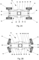
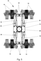
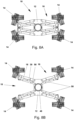
- FIG. 1A to 5 an embodiment of a chassis 10 according to the invention is shown, the components and functioning of which are described in detail below.
- the chassis 10 therefore comprises a base 12 and four wheels 14, which are each arranged on the base 12 via a support device 16.
- the four wheels 14 can be moved by means of the support device 16 from a transport position according to the Fig. 1A into a working position of the chassis 10 according to the Fig. 1B In the transport position, the chassis 10 has a smaller width than in the working position.
- a working machine (not shown) starts normal operation.
- the four wheels 14 can/will be moved from the working position of the chassis 10 by means of the respective support device 16 after use and termination of normal operation of the working machine in accordance with the Fig. 1B back to the transport position according to the Fig. 1A in order to be able to transport the chassis 10, for example on a low loader of a truck, to the next location.
- Each support device 16 comprises a support or carrying arm 18.
- the support or carrying arm 18 is arranged to be pivotable via a proximal end 20 on the base 12 from the transport position into the working position of the chassis 10, and vice versa. Furthermore, the support or carrying arm 18 rotatably receives a steering knuckle 24 at a distal end 22.
- the support or carrying arm 18 is arranged in this context on the base 12 with the proximal end 20 rotatably via a first axis of rotation 26.
- a second axis of rotation 28 is provided on the distal end 22 of the support or carrying arm 18, via which the steering knuckle 24 is articulated or rotatably connected to the support or carrying arm 18.
- each support device 16 comprises a first actuating device 30.
- the first actuating device 30 is provided for pivoting the support or carrying arm 18 from the transport position into the working position of the chassis 10, and vice versa.
- the first actuating device 30 is rotatably arranged on the base 12 via a proximal end 32 and is rotatably connected to the steering knuckle 24 at a distal end 34.
- a first rotation axis 36 which acts between the base 12 and the proximal end 32 of the first actuating device 30, and a second rotation axis 38, which acts between the distal end 34 and the steering knuckle 24, are provided.
- each support device 16 further comprises the steering knuckle 24, which is rotatably arranged on the distal end 22 of the support or carrying arm 18.
- each support device 16 is equipped with a wheel axle 40 in order to rotatably receive the respective associated wheel 14 at a distal end 42 of the steering knuckle 24.
- the wheel axle 40 itself is also hinged to the steering knuckle 24 in order to be able to be pivoted from the transport position to the working position and vice versa when the width of the chassis 10 is adjusted or the track is widened, as well as for steering the chassis 10 in normal operation.
- each support device 16 has a second actuating device 44 for pivoting the wheel axle 40 relative to the steering knuckle 24.
- the design of the chassis 10 according to the invention allows a particularly simple, compact and stable construction of the chassis 10 or chassis as a whole to be achieved. Due to the structural possibility of adjusting the wheels 14 during the width adjustment or track widening of the chassis 10 from the transport position to the working position of the chassis 10, and vice versa, the individual components of the chassis 10 and ultimately the chassis 10 itself are subjected to negligibly small transverse forces. Consequently, the dimensions of the support or carrying arm 18, the first and second actuating devices 30, 44 or other components and the chassis 10 as a whole can be reduced and weight can thus be saved. Accordingly, a design that is less prone to repairs and, not least as a result, an extremely long service life of the chassis 10 can be achieved. The operation of the chassis 10 is also particularly cost-effective as a result.
- the first actuating device 30 and/or the second actuating device 44 is/are preferably adjustable in length
- the first actuating device 30 and/or the second actuating device 44 is/are designed to be hydraulically, pneumatically, mechanically or electrically adjustable in length.
- a pressure cylinder in particular a telescopic one, very preferably an adjusting cylinder or steering cylinder, has proven to be particularly advantageous in practice as the first actuating device 30 or the second actuating device 44.
- the first actuating device 30 and/or the second actuating device 44 it would also be advantageous to design the first actuating device 30 and/or the second actuating device 44 as a hydraulic unit, linear unit, spindle unit or linear motor.
- an individual, pairwise or all common control of the wheels 14 and/or the first actuating device 30 and/or the second actuating device 44 is preferably provided.
- the base 12 of the chassis 10 is Fig. 1A to 5 provided with a - preferably centrally mounted - turntable 46, slewing ring or similar bearing device, whereby a structure, rotating tower, work basket, work platform or other lifting device for the transport of persons and tools (all not shown) can be arranged rotatably on the chassis 10.
- the method according to the invention for width adjustment or track widening of the chassis 10 according to the invention, for example of a self-propelled work machine, from the transport position to the working position is described using the Fig. 2A to 2D explained in more detail:
- the transport position which is in the Fig. 2A
- the brakes of the wheels 14 are first released so that the wheels 14 are in free circulation and can rotate freely. This reduces the load and wear on the wheels 14 and avoid leaving grinding marks on the floor or subfloor.
- the wheels 14 are in a first intermediate position, which is in the Fig. 2B is shown, brought into an angle that is tangential to the (partial) circular path of the respectively associated support and carrying arms 18.
- Precise control is preferably carried out via an angle or length sensor (not shown) which is located in the second actuating device 44, for example a steering cylinder.
- the wheels 14 on the support devices 16 are each aligned at an angle to the longitudinal axis 48 of the chassis 10 for moving or adjusting the width of the chassis 10 from the transport position to the working position and vice versa.
- the wheels 14 are each guided or aligned on, essentially on or parallel to a partial circle around which the support devices 16 are pivoted or moved from the transport position to the working position and vice versa.
- the support and carrying arms 18 are then moved by the first actuating device 30, ie from the transport position or the first intermediate position, in which the support or carrying arms 18 are still approximately parallel to the longitudinal axis 48 of the chassis 10, into a second intermediate position.
- the support or carrying arms 18 are folded out or spread out from the longitudinal axis 48 of the chassis 10.
- precise control is preferably carried out via the angle or length sensor located in the second actuating device 44.
- the wheels 14 simply rotate along with it.
- the wheels 14 are finally moved to the working position, as the Fig. 2D to be taken is moved again parallel to one another or to the longitudinal axis 48 via the second actuating devices 44, for example the steering cylinders.
- precise control is preferably carried out again by the angle or length sensor in the second actuating device 44.
- the working machine (not shown) switches to normal operation and is now available to the operating personnel for the intended work.
- the four wheels 14 are then moved from the working position of the chassis 10 via the respective support device 16 in accordance with the Fig. 1B back via the two intermediate positions to the transport position according to the Fig. 1A so that the chassis 10 can then be transported, for example, on a low loader of a truck for transfer to the next location.
- the Fig.5 Finally, it shows all steering positions of the four wheels 14 and corresponding positions of the support devices 16 (partly dashed) in the transport position, in the two intermediate positions and in the working position.
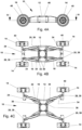
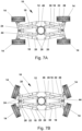
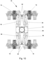
- FIG. 6A to 10 a further embodiment of the chassis 10 according to the invention is shown.
- each support device 16 additionally comprises a parallel guide 50.
- the parallel guides 50 for example in the form of a further support or carrying arm, are in the embodiment of the chassis 10, as can be seen from the Fig. 6A to 10 , their dimensions or dimensions are smaller than those of the support or carrying arms 18. Without being shown in detail, the parallel guides 50 can also have the same or even larger dimensions or dimensions as the support or carrying arms 18. This depends essentially on the force and moment ratios that occur and can be designed as desired and individually adapted to the respective load characteristics of the chassis 12.
- the stability of the chassis 10 as a whole can be further increased and its service life extended with the parallel guides 50 of the vehicle chassis 10 according to the invention. Furthermore, this achieves improved tracking accuracy and fidelity of the chassis 10. This also results in simplified, equally precise handling of the chassis 10 during operation. Finally, the first actuating devices 30 can be protected by the parallel guides 50 against damage or even complete destruction, for example in the event of a collision, if obstacles on the path of the chassis 10 of may be overlooked by the operating personnel due to carelessness.
- each parallel guide 50 is assigned to the corresponding support or carrying arm 18.
- the parallel guide 50 is rotatably arranged on the base 12 via a proximal end 52 and is rotatably connected to the steering knuckle 24 at a distal end 54.
- a first axis of rotation 56 is provided between the base 12 and the proximal end 52 of the parallel guide 50 and a second axis of rotation 58 is provided between the distal end 54 and the steering knuckle 24.
- the parallel guide 50 is arranged between the support and carrying arm 18 and the longitudinal axis 48 of the chassis 10.
- the parallel guide 50 is in particular aligned substantially parallel to the respective support and carrying arm 18.
- the parallel guide 50 and the support and carrying arm 18 together with the base 12 and the steering knuckle 24 form, for example, a parallelogram.
- the chassis design of the Fig. 6A to 10 Furthermore, the first axis of rotation 56 of the parallel guide 50 and the base 12 and the first axis of rotation 36 of the first actuating device 30 and the base 12 coincide. This simplifies the construction and enables weight savings.
- the two embodiments of the chassis 10 according to the invention correspond to the Fig. 1A to 5 and after the Fig. 6A to 10 In this respect, reference is made to the previous description of the embodiment of the Fig. 1A to 5 referred to.
- the invention is not limited to the embodiments shown. Without being shown in detail, it is possible to describe the various embodiments of the chassis 10 according to the invention and its individual components among themselves or with each other individually and arbitrarily. The same applies to the method according to the invention and its use. For example, it is possible to form the second axis of rotation 28 of the support or carrier arm 18 and the steering knuckle 24 and the second axis of rotation 38 of the first actuating device 30 and the steering knuckle 24 separately from each other on/at the steering knuckle 24. In contrast to the illustrated embodiments of the chassis 10 according to the invention according to the Fig.
Landscapes
- Engineering & Computer Science (AREA)
- Mechanical Engineering (AREA)
- Transportation (AREA)
- Structural Engineering (AREA)
- Geology (AREA)
- Life Sciences & Earth Sciences (AREA)
- Civil Engineering (AREA)
- Chemical & Material Sciences (AREA)
- Combustion & Propulsion (AREA)
- Vehicle Cleaning, Maintenance, Repair, Refitting, And Outriggers (AREA)
- Steering-Linkage Mechanisms And Four-Wheel Steering (AREA)
- Forklifts And Lifting Vehicles (AREA)
- Brushes (AREA)
- Handcart (AREA)
Claims (15)
- Châssis comprenant une base (12) et quatre roues (14) agencées chacune sur la base (12) par l'intermédiaire d'un dispositif de soutien (16) et pouvant être déplacées d'une position de transport à une position de travail du châssis (10), et inversement, chaque dispositif de soutien (16) comprenantun bras de soutien ou de support (18) qui est agencé par une extrémité proximale (20) sur la base (12) de manière à pouvoir pivoter de la position de transport à la position de travail du châssis, et inversement,un premier dispositif d'actionnement (30) pour faire pivoter le bras de soutien ou de support (18) de la position de transport à la position de travail du châssis, et inversement,une fusée d'essieu (24) agencée à l'extrémité distale (22) du bras de soutien ou de support (18),un essieu de roue (40) qui est agencé sur la fusée d'essieu (24) de manière à pouvoir pivoter et qui reçoit la roue (14) de manière rotative à une extrémité distale (42) de la fusée d'essieu (24), etun deuxième dispositif d'actionnement (44) pour faire pivoter l'essieu de roue (40) par rapport à la fusée d'essieu (24),caractérisé en ce que la fusée d'essieu (24) est agencée de manière rotative à l'extrémité distale (22) du bras de soutien ou de support (18).
- Châssis selon la revendication 1, caractérisé en ce que le bras de soutien ou de support (18) est agencé par l'extrémité proximale (20) sur la base (12) de manière rotative par l'intermédiaire d'un premier axe de rotation (26) de la position de transport à la position de travail du châssis (10), et inversement, et est relié par l'extrémité distale (22) à la fusée d'essieu (24) de manière rotative par l'intermédiaire d'un deuxième axe de rotation (28).
- Châssis selon la revendication 1 ou 2, caractérisé en ce que le premier dispositif d'actionnement (30) conçu pour faire pivoter le bras de soutien ou de support (18) de la position de transport à la position de travail du châssis (10), et inversement, est agencé par une extrémité proximale (32) sur la base (12) de manière rotative par l'intermédiaire d'un premier axe de rotation (36) et est relié par une extrémité distale (34) à la fusée d'essieu (24) de manière rotative par l'intermédiaire d'un deuxième axe de rotation (38).
- Châssis selon l'une des revendications 1 à 3, caractérisé en ce que le deuxième axe de rotation (28) du bras de soutien ou de support (18) et de la fusée d'essieu (24) et le deuxième axe de rotation (38) du premier dispositif d'actionnement (30) et de la fusée d'essieu (24) sont confondus.
- Châssis selon l'une des revendications 1 à 4, caractérisé en ce que le premier dispositif d'actionnement (30) et/ou le deuxième dispositif d'actionnement (44) est/sont conçu(s) pour être réglable(s) en longueur.
- Châssis selon l'une des revendications 1 à 5, caractérisé en ce que le premier dispositif d'actionnement (30) et/ou le deuxième dispositif d'actionnement (44) est/sont conçu (s) pour être réglable (s) en longueur par voie hydraulique, pneumatique, mécanique ou électrique.
- Châssis selon l'une des revendications 1 à 6, caractérisé en ce que le premier dispositif d'actionnement (30) et/ou le deuxième dispositif d'actionnement (44) est/sont conçu(s) comme un vérin de pression, une unité hydraulique, une unité linéaire, une unité à broche ou un moteur linéaire, en particulier télescopique.
- Châssis selon l'une des revendications 1 à 7, caractérisé en ce que chaque dispositif de soutien (16) comprend en outre un guide parallèle (50) associé au bras de soutien ou de support (18), monté par une extrémité proximale (52) de manière rotative sur la base (12) et relié par une extrémité distale (54) de manière rotative à la fusée d'essieu (24) .
- Châssis selon la revendication 8, caractérisé en ce que le guide parallèle (50) est agencé entre le bras de soutien et de support (18) et l'axe longitudinal (48) du châssis (10), en particulier sensiblement parallèlement au bras de soutien et de support (18).
- Châssis selon l'une des revendications 8 ou 9, caractérisé en ce que le guide parallèle (50) et le bras de soutien et de support (18) constituent, conjointement avec la base (12) et la fusée d'essieu (24), sensiblement la forme d'un parallélogramme.
- Châssis selon la revendication 3 et l'une des revendications 8 à 10, caractérisé en ce qu'un premier axe de rotation (56) du guide parallèle (50) et de la base (12) et le premier axe de rotation (36) du premier dispositif d'actionnement (30) et de la base (12) sont confondus.
- Châssis selon l'une des revendications 1 à 11, caractérisé en ce que les roues (14) et/ou le premier dispositif d'actionnement (30) et/ou le deuxième dispositif d'actionnement (44) est/sont conçu(s) pour être commandé(s) individuellement, par paire ou tous conjointement.
- Châssis selon l'une des revendications 1 à 12, caractérisé en ce que la base (12) comporte un plateau tournant (46), une couronne de rotation ou un dispositif de montage similaire, permettant d'agencer de manière rotative une superstructure, une tour rotative, une nacelle, une plate-forme de travail ou un autre dispositif de levage pour le transport de personnes et d'outils.
- Procédé de fonctionnement d'une machine de travail, d'une plate-forme de travail, ou similaire, mobile ou automotrice, comprenant un châssis selon l'une des revendications 1 à 13, caractérisé en ce que les roues (14) agencées sur des dispositifs de soutien (16) sont orientées chacune selon un angle par rapport à l'axe longitudinal (48) du châssis (10), par l'intermédiaire d'une fusée d'essieu (24) agencée de manière rotative sur une extrémité distale (22) d'un bras de soutien ou de support (18) des dispositifs de soutien (16) pour le réglage en largeur du châssis (10) ou pour le déplacement du châssis (10) de la position de transport à la position de travail, et inversement, de telle sorte que les roues (14) sont guidées ou orientées chacune sensiblement sur ou parallèlement à un cercle primitif autour duquel ou sur lequel les dispositifs de support (16) sont pivotés ou déplacés.
- Utilisation d'un châssis selon l'une des revendications 1 à 13, pour des machines de travail, des plateformes de travail, des nacelles, mobiles, déplaçables, susceptibles d'être levées et abaissées, automotrices, des excavateurs, des machines pour le dragage, des pelles araignées, des engins et machines de chantier, des élévateurs à flèche, des engins de terrassement, des tarières, des plates-formes élévatrices, des équipements de levage pour le transport de personnes et de marchandises, des élévateurs, des plates-formes élévatrices de travail, des tables élévatrices, des grues, des grues tournantes, des grues de chantier et des camions-grues, des ponts roulants, des portiques, des grues à tour, des potences ou des porte-outils pour machines-outils.
Applications Claiming Priority (2)
| Application Number | Priority Date | Filing Date | Title |
|---|---|---|---|
| DE102020130811.6A DE102020130811A1 (de) | 2020-11-20 | 2020-11-20 | Fahrgestell und dessen Verwendung |
| PCT/EP2021/081248 WO2022106280A1 (fr) | 2020-11-20 | 2021-11-10 | Châssis et son utilisation |
Publications (2)
| Publication Number | Publication Date |
|---|---|
| EP4232300A1 EP4232300A1 (fr) | 2023-08-30 |
| EP4232300B1 true EP4232300B1 (fr) | 2024-08-21 |
Family
ID=78725458
Family Applications (1)
| Application Number | Title | Priority Date | Filing Date |
|---|---|---|---|
| EP21811276.1A Active EP4232300B1 (fr) | 2020-11-20 | 2021-11-10 | Châssis et son utilisation |
Country Status (7)
| Country | Link |
|---|---|
| US (1) | US20230406039A1 (fr) |
| EP (1) | EP4232300B1 (fr) |
| CN (1) | CN116457222B (fr) |
| AU (1) | AU2021381549B2 (fr) |
| DE (1) | DE102020130811A1 (fr) |
| ES (1) | ES2994219T3 (fr) |
| WO (1) | WO2022106280A1 (fr) |
Cited By (1)
| Publication number | Priority date | Publication date | Assignee | Title |
|---|---|---|---|---|
| EP4019301A1 (fr) * | 2020-12-28 | 2022-06-29 | MARMIX GmbH & Co. KG | Dispositif d'essieu à écartement de la voie variable, véhicule spécial et son utilisation |
Families Citing this family (3)
| Publication number | Priority date | Publication date | Assignee | Title |
|---|---|---|---|---|
| WO2023180687A1 (fr) * | 2022-03-23 | 2023-09-28 | Bae Systems Plc | Système de suspension |
| US20230391137A1 (en) * | 2022-06-06 | 2023-12-07 | Zoomlion Heavy Industry Na, Inc. | Telehandler Having Tilt Axle With An Extendable Track |
| CN115626220A (zh) * | 2022-11-23 | 2023-01-20 | 浙江鼎力机械股份有限公司 | 一种行驶底盘原地扩桥的控制方法 |
Family Cites Families (10)
| Publication number | Priority date | Publication date | Assignee | Title |
|---|---|---|---|---|
| US6443687B1 (en) | 1997-05-23 | 2002-09-03 | Kaiser Aktiengesellschaft | Excavator-hoist |
| WO2005056308A1 (fr) * | 2003-12-11 | 2005-06-23 | Singapore Technologies Kinetics Ltd | Systeme de reglage de voie |
| JP4405885B2 (ja) * | 2004-09-24 | 2010-01-27 | 株式会社クボタ | 水田作業車 |
| DE102008028352A1 (de) * | 2008-06-13 | 2009-12-17 | Dr. Ing. H.C. F. Porsche Aktiengesellschaft | Stabilisatoranordnung |
| CN101554895B (zh) * | 2009-05-14 | 2011-06-08 | 上海交通大学 | 月球车行走折叠系统 |
| FR2976850B1 (fr) | 2011-06-23 | 2013-07-12 | Haulotte Group | Demi-essieu, et vehicule comprenant au moins un tel demi-essieu |
| US8888122B2 (en) * | 2012-03-19 | 2014-11-18 | Jlg Industries, Inc. | Pivoting axle system |
| CN106080833A (zh) | 2016-08-05 | 2016-11-09 | 湖南星邦重工有限公司 | 一种高空作业设备及其底盘 |
| GB2562539A (en) * | 2017-05-19 | 2018-11-21 | Bamford Excavators Ltd | Working machine |
| US10562364B2 (en) | 2017-08-02 | 2020-02-18 | California Manufacturing & Engineering Company, Llc | Vehicle wheel positioning and steering apparatus |
-
2020
- 2020-11-20 DE DE102020130811.6A patent/DE102020130811A1/de active Pending
-
2021
- 2021-11-10 CN CN202180077606.3A patent/CN116457222B/zh active Active
- 2021-11-10 WO PCT/EP2021/081248 patent/WO2022106280A1/fr not_active Ceased
- 2021-11-10 EP EP21811276.1A patent/EP4232300B1/fr active Active
- 2021-11-10 ES ES21811276T patent/ES2994219T3/es active Active
- 2021-11-10 US US18/033,355 patent/US20230406039A1/en not_active Abandoned
- 2021-11-10 AU AU2021381549A patent/AU2021381549B2/en active Active
Cited By (1)
| Publication number | Priority date | Publication date | Assignee | Title |
|---|---|---|---|---|
| EP4019301A1 (fr) * | 2020-12-28 | 2022-06-29 | MARMIX GmbH & Co. KG | Dispositif d'essieu à écartement de la voie variable, véhicule spécial et son utilisation |
Also Published As
| Publication number | Publication date |
|---|---|
| ES2994219T3 (en) | 2025-01-20 |
| CN116457222B (zh) | 2025-10-28 |
| CN116457222A (zh) | 2023-07-18 |
| US20230406039A1 (en) | 2023-12-21 |
| AU2021381549B2 (en) | 2024-03-28 |
| EP4232300A1 (fr) | 2023-08-30 |
| DE102020130811A1 (de) | 2022-05-25 |
| AU2021381549A1 (en) | 2023-05-11 |
| WO2022106280A1 (fr) | 2022-05-27 |
| AU2021381549A9 (en) | 2024-10-24 |
Similar Documents
| Publication | Publication Date | Title |
|---|---|---|
| EP4232300B1 (fr) | Châssis et son utilisation | |
| EP2218836B1 (fr) | Véhicule, notamment véhicule de chantier | |
| EP1466856B1 (fr) | Grue mobile avec un dispositif de stabilisation | |
| DE2658250A1 (de) | Fahrbarer und hebbarer arbeitskorb | |
| DE102016008822B4 (de) | Mobilkran mit verstellbarer Ballastaufnahmevorrichtung | |
| EP0847348B1 (fr) | Engin mobile a bras d'appui a pivotement lateral | |
| DE2119164C2 (de) | Fahrbare Maschine zum Verlegen und/oder Aufnehmen von Querschwellen eines Gleises | |
| DE69429188T2 (de) | Hebevorrichtung zum handhaben eines gleiselements | |
| DE69922668T2 (de) | Auslegeranordnung für eine gesteinbohreinheit | |
| EP1621682A2 (fr) | Appareil de transbordement. | |
| EP1580331B1 (fr) | Chassis pour machines mobiles de travaux publics | |
| DE3416033C2 (fr) | ||
| EP1245740B1 (fr) | Véhicule de chantier avec un outil de travail | |
| EP2503063A2 (fr) | Véhicule équipé d'un châssis élévateur et d'un soc niveleur | |
| EP2886505B1 (fr) | Grue | |
| DE4409514C2 (de) | Verstellbares Gegengewicht für eine Baumaschine und Hydraulikbagger, der mit einem verstellbaren Gegengewicht ausgerüstet ist | |
| DE2843587A1 (de) | Hebebuehne mit ausleger | |
| DE102012001377B4 (de) | Ballastwagen für einen Derrickkran | |
| DE2361566C3 (de) | Bohrvorrichtung | |
| DE2022844C3 (de) | Kranunterwagen mit für den Straßen- und Schienentransport unterschiedlich einstelbarem Bodenabstand | |
| DE19806224A1 (de) | Verfahren und Vorrichtung zum Drehen von schweren quaderförmigen Lasten, insbesondere Stahlbrammen | |
| EP0581103A1 (fr) | Appareil pour le travail du sol | |
| EP0927698B1 (fr) | Appareil de travail sur roues mobile transversalement | |
| DE2953069C3 (de) | Hubwagen mit beweglicher Arbeitsvorrichtung | |
| DE2725042C2 (de) | Bohrwagen für Senkrechtbohrungen |
Legal Events
| Date | Code | Title | Description |
|---|---|---|---|
| STAA | Information on the status of an ep patent application or granted ep patent |
Free format text: STATUS: UNKNOWN |
|
| STAA | Information on the status of an ep patent application or granted ep patent |
Free format text: STATUS: THE INTERNATIONAL PUBLICATION HAS BEEN MADE |
|
| PUAI | Public reference made under article 153(3) epc to a published international application that has entered the european phase |
Free format text: ORIGINAL CODE: 0009012 |
|
| STAA | Information on the status of an ep patent application or granted ep patent |
Free format text: STATUS: REQUEST FOR EXAMINATION WAS MADE |
|
| STAA | Information on the status of an ep patent application or granted ep patent |
Free format text: STATUS: EXAMINATION IS IN PROGRESS |
|
| 17P | Request for examination filed |
Effective date: 20230522 |
|
| AK | Designated contracting states |
Kind code of ref document: A1 Designated state(s): AL AT BE BG CH CY CZ DE DK EE ES FI FR GB GR HR HU IE IS IT LI LT LU LV MC MK MT NL NO PL PT RO RS SE SI SK SM TR |
|
| 17Q | First examination report despatched |
Effective date: 20230822 |
|
| DAV | Request for validation of the european patent (deleted) | ||
| DAX | Request for extension of the european patent (deleted) | ||
| GRAP | Despatch of communication of intention to grant a patent |
Free format text: ORIGINAL CODE: EPIDOSNIGR1 |
|
| STAA | Information on the status of an ep patent application or granted ep patent |
Free format text: STATUS: GRANT OF PATENT IS INTENDED |
|
| INTG | Intention to grant announced |
Effective date: 20240320 |
|
| GRAS | Grant fee paid |
Free format text: ORIGINAL CODE: EPIDOSNIGR3 |
|
| GRAA | (expected) grant |
Free format text: ORIGINAL CODE: 0009210 |
|
| STAA | Information on the status of an ep patent application or granted ep patent |
Free format text: STATUS: THE PATENT HAS BEEN GRANTED |
|
| AK | Designated contracting states |
Kind code of ref document: B1 Designated state(s): AL AT BE BG CH CY CZ DE DK EE ES FI FR GB GR HR HU IE IS IT LI LT LU LV MC MK MT NL NO PL PT RO RS SE SI SK SM TR |
|
| RAP3 | Party data changed (applicant data changed or rights of an application transferred) |
Owner name: TEUPEN MASCHINENBAU GMBH |
|
| REG | Reference to a national code |
Ref country code: GB Ref legal event code: FG4D Free format text: NOT ENGLISH |
|
| REG | Reference to a national code |
Ref country code: CH Ref legal event code: EP |
|
| REG | Reference to a national code |
Ref country code: DE Ref legal event code: R096 Ref document number: 502021004902 Country of ref document: DE |
|
| REG | Reference to a national code |
Ref country code: IE Ref legal event code: FG4D Free format text: LANGUAGE OF EP DOCUMENT: GERMAN |
|
| REG | Reference to a national code |
Ref country code: NL Ref legal event code: FP |
|
| REG | Reference to a national code |
Ref country code: LT Ref legal event code: MG9D |
|
| PG25 | Lapsed in a contracting state [announced via postgrant information from national office to epo] |
Ref country code: NO Free format text: LAPSE BECAUSE OF FAILURE TO SUBMIT A TRANSLATION OF THE DESCRIPTION OR TO PAY THE FEE WITHIN THE PRESCRIBED TIME-LIMIT Effective date: 20241121 |
|
| PG25 | Lapsed in a contracting state [announced via postgrant information from national office to epo] |
Ref country code: PT Free format text: LAPSE BECAUSE OF FAILURE TO SUBMIT A TRANSLATION OF THE DESCRIPTION OR TO PAY THE FEE WITHIN THE PRESCRIBED TIME-LIMIT Effective date: 20241223 Ref country code: GR Free format text: LAPSE BECAUSE OF FAILURE TO SUBMIT A TRANSLATION OF THE DESCRIPTION OR TO PAY THE FEE WITHIN THE PRESCRIBED TIME-LIMIT Effective date: 20241122 Ref country code: FI Free format text: LAPSE BECAUSE OF FAILURE TO SUBMIT A TRANSLATION OF THE DESCRIPTION OR TO PAY THE FEE WITHIN THE PRESCRIBED TIME-LIMIT Effective date: 20240821 Ref country code: PL Free format text: LAPSE BECAUSE OF FAILURE TO SUBMIT A TRANSLATION OF THE DESCRIPTION OR TO PAY THE FEE WITHIN THE PRESCRIBED TIME-LIMIT Effective date: 20240821 |
|
| PG25 | Lapsed in a contracting state [announced via postgrant information from national office to epo] |
Ref country code: BG Free format text: LAPSE BECAUSE OF FAILURE TO SUBMIT A TRANSLATION OF THE DESCRIPTION OR TO PAY THE FEE WITHIN THE PRESCRIBED TIME-LIMIT Effective date: 20240821 |
|
| REG | Reference to a national code |
Ref country code: ES Ref legal event code: FG2A Ref document number: 2994219 Country of ref document: ES Kind code of ref document: T3 Effective date: 20250120 |
|
| PG25 | Lapsed in a contracting state [announced via postgrant information from national office to epo] |
Ref country code: LV Free format text: LAPSE BECAUSE OF FAILURE TO SUBMIT A TRANSLATION OF THE DESCRIPTION OR TO PAY THE FEE WITHIN THE PRESCRIBED TIME-LIMIT Effective date: 20240821 |
|
| PG25 | Lapsed in a contracting state [announced via postgrant information from national office to epo] |
Ref country code: IS Free format text: LAPSE BECAUSE OF FAILURE TO SUBMIT A TRANSLATION OF THE DESCRIPTION OR TO PAY THE FEE WITHIN THE PRESCRIBED TIME-LIMIT Effective date: 20241221 |
|
| PG25 | Lapsed in a contracting state [announced via postgrant information from national office to epo] |
Ref country code: HR Free format text: LAPSE BECAUSE OF FAILURE TO SUBMIT A TRANSLATION OF THE DESCRIPTION OR TO PAY THE FEE WITHIN THE PRESCRIBED TIME-LIMIT Effective date: 20240821 |
|
| PG25 | Lapsed in a contracting state [announced via postgrant information from national office to epo] |
Ref country code: RS Free format text: LAPSE BECAUSE OF FAILURE TO SUBMIT A TRANSLATION OF THE DESCRIPTION OR TO PAY THE FEE WITHIN THE PRESCRIBED TIME-LIMIT Effective date: 20241121 |
|
| PG25 | Lapsed in a contracting state [announced via postgrant information from national office to epo] |
Ref country code: RS Free format text: LAPSE BECAUSE OF FAILURE TO SUBMIT A TRANSLATION OF THE DESCRIPTION OR TO PAY THE FEE WITHIN THE PRESCRIBED TIME-LIMIT Effective date: 20241121 Ref country code: PT Free format text: LAPSE BECAUSE OF FAILURE TO SUBMIT A TRANSLATION OF THE DESCRIPTION OR TO PAY THE FEE WITHIN THE PRESCRIBED TIME-LIMIT Effective date: 20241223 Ref country code: PL Free format text: LAPSE BECAUSE OF FAILURE TO SUBMIT A TRANSLATION OF THE DESCRIPTION OR TO PAY THE FEE WITHIN THE PRESCRIBED TIME-LIMIT Effective date: 20240821 Ref country code: NO Free format text: LAPSE BECAUSE OF FAILURE TO SUBMIT A TRANSLATION OF THE DESCRIPTION OR TO PAY THE FEE WITHIN THE PRESCRIBED TIME-LIMIT Effective date: 20241121 Ref country code: LV Free format text: LAPSE BECAUSE OF FAILURE TO SUBMIT A TRANSLATION OF THE DESCRIPTION OR TO PAY THE FEE WITHIN THE PRESCRIBED TIME-LIMIT Effective date: 20240821 Ref country code: IS Free format text: LAPSE BECAUSE OF FAILURE TO SUBMIT A TRANSLATION OF THE DESCRIPTION OR TO PAY THE FEE WITHIN THE PRESCRIBED TIME-LIMIT Effective date: 20241221 Ref country code: HR Free format text: LAPSE BECAUSE OF FAILURE TO SUBMIT A TRANSLATION OF THE DESCRIPTION OR TO PAY THE FEE WITHIN THE PRESCRIBED TIME-LIMIT Effective date: 20240821 Ref country code: GR Free format text: LAPSE BECAUSE OF FAILURE TO SUBMIT A TRANSLATION OF THE DESCRIPTION OR TO PAY THE FEE WITHIN THE PRESCRIBED TIME-LIMIT Effective date: 20241122 Ref country code: FI Free format text: LAPSE BECAUSE OF FAILURE TO SUBMIT A TRANSLATION OF THE DESCRIPTION OR TO PAY THE FEE WITHIN THE PRESCRIBED TIME-LIMIT Effective date: 20240821 Ref country code: BG Free format text: LAPSE BECAUSE OF FAILURE TO SUBMIT A TRANSLATION OF THE DESCRIPTION OR TO PAY THE FEE WITHIN THE PRESCRIBED TIME-LIMIT Effective date: 20240821 |
|
| RAP2 | Party data changed (patent owner data changed or rights of a patent transferred) |
Owner name: ZHEJIANG DINGLI MACHINERY CO., LTD |
|
| PG25 | Lapsed in a contracting state [announced via postgrant information from national office to epo] |
Ref country code: SM Free format text: LAPSE BECAUSE OF FAILURE TO SUBMIT A TRANSLATION OF THE DESCRIPTION OR TO PAY THE FEE WITHIN THE PRESCRIBED TIME-LIMIT Effective date: 20240821 Ref country code: RO Free format text: LAPSE BECAUSE OF FAILURE TO SUBMIT A TRANSLATION OF THE DESCRIPTION OR TO PAY THE FEE WITHIN THE PRESCRIBED TIME-LIMIT Effective date: 20240821 Ref country code: DK Free format text: LAPSE BECAUSE OF FAILURE TO SUBMIT A TRANSLATION OF THE DESCRIPTION OR TO PAY THE FEE WITHIN THE PRESCRIBED TIME-LIMIT Effective date: 20240821 |
|
| PG25 | Lapsed in a contracting state [announced via postgrant information from national office to epo] |
Ref country code: EE Free format text: LAPSE BECAUSE OF FAILURE TO SUBMIT A TRANSLATION OF THE DESCRIPTION OR TO PAY THE FEE WITHIN THE PRESCRIBED TIME-LIMIT Effective date: 20240821 |
|
| PG25 | Lapsed in a contracting state [announced via postgrant information from national office to epo] |
Ref country code: CZ Free format text: LAPSE BECAUSE OF FAILURE TO SUBMIT A TRANSLATION OF THE DESCRIPTION OR TO PAY THE FEE WITHIN THE PRESCRIBED TIME-LIMIT Effective date: 20240821 |
|
| PG25 | Lapsed in a contracting state [announced via postgrant information from national office to epo] |
Ref country code: SK Free format text: LAPSE BECAUSE OF FAILURE TO SUBMIT A TRANSLATION OF THE DESCRIPTION OR TO PAY THE FEE WITHIN THE PRESCRIBED TIME-LIMIT Effective date: 20240821 |
|
| REG | Reference to a national code |
Ref country code: DE Ref legal event code: R097 Ref document number: 502021004902 Country of ref document: DE |
|
| PLBE | No opposition filed within time limit |
Free format text: ORIGINAL CODE: 0009261 |
|
| STAA | Information on the status of an ep patent application or granted ep patent |
Free format text: STATUS: NO OPPOSITION FILED WITHIN TIME LIMIT |
|
| PG25 | Lapsed in a contracting state [announced via postgrant information from national office to epo] |
Ref country code: MC Free format text: LAPSE BECAUSE OF FAILURE TO SUBMIT A TRANSLATION OF THE DESCRIPTION OR TO PAY THE FEE WITHIN THE PRESCRIBED TIME-LIMIT Effective date: 20240821 |
|
| PG25 | Lapsed in a contracting state [announced via postgrant information from national office to epo] |
Ref country code: LU Free format text: LAPSE BECAUSE OF NON-PAYMENT OF DUE FEES Effective date: 20241110 |
|
| 26N | No opposition filed |
Effective date: 20250522 |
|
| REG | Reference to a national code |
Ref country code: BE Ref legal event code: MM Effective date: 20241130 |
|
| PG25 | Lapsed in a contracting state [announced via postgrant information from national office to epo] |
Ref country code: SE Free format text: LAPSE BECAUSE OF FAILURE TO SUBMIT A TRANSLATION OF THE DESCRIPTION OR TO PAY THE FEE WITHIN THE PRESCRIBED TIME-LIMIT Effective date: 20240821 |
|
| PG25 | Lapsed in a contracting state [announced via postgrant information from national office to epo] |
Ref country code: BE Free format text: LAPSE BECAUSE OF NON-PAYMENT OF DUE FEES Effective date: 20241130 |
|
| PG25 | Lapsed in a contracting state [announced via postgrant information from national office to epo] |
Ref country code: IE Free format text: LAPSE BECAUSE OF NON-PAYMENT OF DUE FEES Effective date: 20241110 |
|
| REG | Reference to a national code |
Ref country code: CH Ref legal event code: U11 Free format text: ST27 STATUS EVENT CODE: U-0-0-U10-U11 (AS PROVIDED BY THE NATIONAL OFFICE) Effective date: 20251201 |
|
| PGFP | Annual fee paid to national office [announced via postgrant information from national office to epo] |
Ref country code: NL Payment date: 20251119 Year of fee payment: 5 |
|
| PGFP | Annual fee paid to national office [announced via postgrant information from national office to epo] |
Ref country code: DE Payment date: 20251110 Year of fee payment: 5 |
|
| PGFP | Annual fee paid to national office [announced via postgrant information from national office to epo] |
Ref country code: GB Payment date: 20251120 Year of fee payment: 5 |
|
| PGFP | Annual fee paid to national office [announced via postgrant information from national office to epo] |
Ref country code: AT Payment date: 20260113 Year of fee payment: 5 |
|
| PGFP | Annual fee paid to national office [announced via postgrant information from national office to epo] |
Ref country code: IT Payment date: 20251128 Year of fee payment: 5 |
|
| PGFP | Annual fee paid to national office [announced via postgrant information from national office to epo] |
Ref country code: FR Payment date: 20251125 Year of fee payment: 5 |
|
| PGFP | Annual fee paid to national office [announced via postgrant information from national office to epo] |
Ref country code: CH Payment date: 20251201 Year of fee payment: 5 |
|
| PGFP | Annual fee paid to national office [announced via postgrant information from national office to epo] |
Ref country code: ES Payment date: 20251216 Year of fee payment: 5 |
|
| PG25 | Lapsed in a contracting state [announced via postgrant information from national office to epo] |
Ref country code: HU Free format text: LAPSE BECAUSE OF FAILURE TO SUBMIT A TRANSLATION OF THE DESCRIPTION OR TO PAY THE FEE WITHIN THE PRESCRIBED TIME-LIMIT; INVALID AB INITIO Effective date: 20211110 |
|
| PG25 | Lapsed in a contracting state [announced via postgrant information from national office to epo] |
Ref country code: CY Free format text: LAPSE BECAUSE OF FAILURE TO SUBMIT A TRANSLATION OF THE DESCRIPTION OR TO PAY THE FEE WITHIN THE PRESCRIBED TIME-LIMIT; INVALID AB INITIO Effective date: 20211110 |