EP4232369B1 - Abnehmbarer deckel zum verschliessen der öffnung eines behälters - Google Patents
Abnehmbarer deckel zum verschliessen der öffnung eines behälters Download PDFInfo
- Publication number
- EP4232369B1 EP4232369B1 EP21819195.5A EP21819195A EP4232369B1 EP 4232369 B1 EP4232369 B1 EP 4232369B1 EP 21819195 A EP21819195 A EP 21819195A EP 4232369 B1 EP4232369 B1 EP 4232369B1
- Authority
- EP
- European Patent Office
- Prior art keywords
- clamping member
- lid
- lid base
- container
- locking
- Prior art date
- Legal status (The legal status is an assumption and is not a legal conclusion. Google has not performed a legal analysis and makes no representation as to the accuracy of the status listed.)
- Active
Links
Images
Classifications
-
- B—PERFORMING OPERATIONS; TRANSPORTING
- B65—CONVEYING; PACKING; STORING; HANDLING THIN OR FILAMENTARY MATERIAL
- B65D—CONTAINERS FOR STORAGE OR TRANSPORT OF ARTICLES OR MATERIALS, e.g. BAGS, BARRELS, BOTTLES, BOXES, CANS, CARTONS, CRATES, DRUMS, JARS, TANKS, HOPPERS, FORWARDING CONTAINERS; ACCESSORIES, CLOSURES, OR FITTINGS THEREFOR; PACKAGING ELEMENTS; PACKAGES
- B65D17/00—Rigid or semi-rigid containers specially constructed to be opened by cutting or piercing, or by tearing of frangible members or portions
- B65D17/28—Rigid or semi-rigid containers specially constructed to be opened by cutting or piercing, or by tearing of frangible members or portions at lines or points of weakness
- B65D17/401—Rigid or semi-rigid containers specially constructed to be opened by cutting or piercing, or by tearing of frangible members or portions at lines or points of weakness characterised by having the line of weakness provided in an end wall
- B65D17/4012—Rigid or semi-rigid containers specially constructed to be opened by cutting or piercing, or by tearing of frangible members or portions at lines or points of weakness characterised by having the line of weakness provided in an end wall for opening partially by means of a tearing tab
- B65D17/4014—Rigid or semi-rigid containers specially constructed to be opened by cutting or piercing, or by tearing of frangible members or portions at lines or points of weakness characterised by having the line of weakness provided in an end wall for opening partially by means of a tearing tab and provided with attached means for reclosing or resealing
-
- B—PERFORMING OPERATIONS; TRANSPORTING
- B65—CONVEYING; PACKING; STORING; HANDLING THIN OR FILAMENTARY MATERIAL
- B65D—CONTAINERS FOR STORAGE OR TRANSPORT OF ARTICLES OR MATERIALS, e.g. BAGS, BARRELS, BOTTLES, BOXES, CANS, CARTONS, CRATES, DRUMS, JARS, TANKS, HOPPERS, FORWARDING CONTAINERS; ACCESSORIES, CLOSURES, OR FITTINGS THEREFOR; PACKAGING ELEMENTS; PACKAGES
- B65D51/00—Closures not otherwise provided for
- B65D51/18—Arrangements of closures with protective outer cap-like covers or of two or more co-operating closures
- B65D51/20—Caps, lids, or covers co-operating with an inner closure arranged to be opened by piercing, cutting, or tearing
-
- B—PERFORMING OPERATIONS; TRANSPORTING
- B65—CONVEYING; PACKING; STORING; HANDLING THIN OR FILAMENTARY MATERIAL
- B65D—CONTAINERS FOR STORAGE OR TRANSPORT OF ARTICLES OR MATERIALS, e.g. BAGS, BARRELS, BOTTLES, BOXES, CANS, CARTONS, CRATES, DRUMS, JARS, TANKS, HOPPERS, FORWARDING CONTAINERS; ACCESSORIES, CLOSURES, OR FITTINGS THEREFOR; PACKAGING ELEMENTS; PACKAGES
- B65D2517/00—Containers specially constructed to be opened by cutting, piercing or tearing of wall portions, e.g. preserving cans or tins
- B65D2517/0001—Details
- B65D2517/0031—Reclosable openings
- B65D2517/004—Reclosable openings by means of an additional element
-
- B—PERFORMING OPERATIONS; TRANSPORTING
- B65—CONVEYING; PACKING; STORING; HANDLING THIN OR FILAMENTARY MATERIAL
- B65D—CONTAINERS FOR STORAGE OR TRANSPORT OF ARTICLES OR MATERIALS, e.g. BAGS, BARRELS, BOTTLES, BOXES, CANS, CARTONS, CRATES, DRUMS, JARS, TANKS, HOPPERS, FORWARDING CONTAINERS; ACCESSORIES, CLOSURES, OR FITTINGS THEREFOR; PACKAGING ELEMENTS; PACKAGES
- B65D2517/00—Containers specially constructed to be opened by cutting, piercing or tearing of wall portions, e.g. preserving cans or tins
- B65D2517/0001—Details
- B65D2517/0031—Reclosable openings
- B65D2517/004—Reclosable openings by means of an additional element
- B65D2517/0041—Reclosable openings by means of an additional element in the form of a cover
-
- B—PERFORMING OPERATIONS; TRANSPORTING
- B65—CONVEYING; PACKING; STORING; HANDLING THIN OR FILAMENTARY MATERIAL
- B65D—CONTAINERS FOR STORAGE OR TRANSPORT OF ARTICLES OR MATERIALS, e.g. BAGS, BARRELS, BOTTLES, BOXES, CANS, CARTONS, CRATES, DRUMS, JARS, TANKS, HOPPERS, FORWARDING CONTAINERS; ACCESSORIES, CLOSURES, OR FITTINGS THEREFOR; PACKAGING ELEMENTS; PACKAGES
- B65D2517/00—Containers specially constructed to be opened by cutting, piercing or tearing of wall portions, e.g. preserving cans or tins
- B65D2517/0001—Details
- B65D2517/0047—Provided with additional elements other than for closing the opening
- B65D2517/0049—Straws, spouts, funnels, or other devices facilitating pouring or emptying
Definitions
- the subject of the invention is a removable lid to close the opening of a container, especially for re-close after opening of beverage storage metal cans, which has a lid base with pour opening, a cap to cover the pour opening, as well as an adapter that connects the lid base to the container, one of the fastening element of the lid base located near to pour opening, while the cap has another fastening element cooperating with one fastening element, and the cap is reversible and removably pinched to the pour opening of the lid base by the other fastening element.
- Such a screw cap can be cognizable in, inter alia, industrial property document CN 2249724 .
- bottles that can be filled with liquid for storage, and the top of the container can be closed with a specially designed lid.
- a beverage container is described in CN 2442 569 . While the utility model description number HU U 4735 can be screwed onto a bottle and describes a cap assembly with a straw.
- the disadvantage of such beverage storage units is that the entire contents of the can must be consumed in a short time, otherwise its enjoyment value deteriorates rapidly.
- Another disadvantage of such cans is that the stored beverage can easily spill out of the storage space, which can cause contamination on the consumer's clothing or its surroundings.
- the purpose of invention is to overcome the shortcomings of the known bottle closure solutions and to create a version which, on the one hand, is suitable to allow the can to be resealed without leakage after opening the can, even in the case of beverages with metal cans, as well as to allow the contents of cans to be consumed more hygienically.
- sample lid unit be reusable and can be used for containers that have a cap or lid but its repeated use does not meet the requirement for a leak-proof seal. For example, in case of pickles and mason jars, which available in stores.
- the basic idea of the invention was that the circumferential surface of the metal cans can be gripped without displacement with a rim-like structural element stretched from the side, and thus the opening of the metal can could be closed with a lid placed on it.
- the design according to the invention was led by the realization that if an adapter can be assembled from two specially shaped clamping members and connected to each other, the pieces can be clamped to the new surface the lid base tensioning the two clamping members is connected, the combination of the two clamping members and the lid base is able to seal the opening can be kept leak-free, and thus the task can be solved.
- the removable lid according to the invention comprises the features of claim 1.
- the seal is partially pressed against the surface of the container in the closed position of the lid base.
- the locking piece has a pin
- one join piece and the other join piece has the shape of a bent arm with a receiving socket, and the pin of locking profile is rotatably inserted into the receiving socket.
- one connecting member of one clamping member has a receiving socket
- the other connecting member of the other fastening element has a shape of a bent arm that fits into the receiving socket of one connecting member is inserted into its slit, and one clamping member and the other clamping member are thus connected to each other.
- one of the clamping members has anti-slip profiles on the support side facing the container and the other side of the support member towards the container.
- the removable lid if the lid base is provided with a closing projection and the closing projection has one locking member, while one of the gripping members and the other clamping member is one of the locking members connected to another locking member cooperating with one locking member of the closing projection is fixed to the adapter without displacement.
- the lid base is provided with a pressure reducing valve.
- the removable lid according to the invention has a number of advantageous features. The most important of these is that with an adapter made of specially shaped clamping members, as a pliers, the mantle surface of the container can be gripped so that the lid base connected to the connection body can be properly pressed onto the open surface of the container, and so that the container, especially the beverage cans made of metal, can be closed after opening.
- a further advantage is that the removable lid can be used countless times due to the design of the adapter and its novel connection with the lid base. Easy to assemble and disassemble and easy to clean.
- Another advantage is that with a suitable lid base design, it is possible to remove content from the container through a small opening, or to introduce it into the container. And so it does not have to open the entire lid base.
- connection body and the lid base prevent leakage, so that the liquid placed in the container can be easily and safely stored and transported even after the original closing plate of the pour opening has been removed.
- Another advantage is that in the event of damage to individual components, its replacement can be easily solved, it does not require special expertise, so the lifetime of the product can be long.
- the removable lid can be used for promotional purposes in addition to its functional use, and thus can also be used as a marketing tool, e.g. to increase for sales of beverages in metal cans.
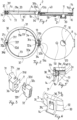
- FIGS 1 and 2 show a possible variant of the removable lid 2 according to the invention, which can be retrofitted to the beverage cans made of metal used as a container 1 and removably.
- the removable lid 2 consists of two main pieces,
- the removable lid 2 consists of two main parts, the lid base 10 and the adapter 30.
- the lid base 10 is basically formed by a pour opening 11 which is surrounded by one of the fastening elements 12. This pour opening 11 serves to secure the removable lid 2 after it has been fixed the liquid can be poured from the container 1 through it, if appropriate, introduced into the container 1 through the pour opening 11.
- the pour opening 11 of the lid base 10 is closed by the cap 20.
- the cap 20 has a second fastening element 21 cooperating with one of the fastening element 12, by means of which the cap 20 can be fastened to one of the fastening element 12 surrounding the pour opening 11 in a liquid-tight manner.
- one of the fastening elements 12 to the other fastening element 21 forms a pair of threads, which is common with screw caps.
- the lid base 10 also includes a pressure reducing valve 50, which is optional but may be advantageous in order to reduce the pressure of the carbonated beverage in the container 1 by means of this pressure reducing valve 50 before the cap 20 is opened.
- a pressure reducing valve 50 which is optional but may be advantageous in order to reduce the pressure of the carbonated beverage in the container 1 by means of this pressure reducing valve 50 before the cap 20 is opened.
- the adapter 30 is composed of a first clamping member 31 and a second clamping member 32.
- the first clamping member 31 is provided at one end 31a with a join piece 31b and at the other end 31c with a connector 32d.
- the second clamping member 32 is provided at one end 32a with a second join piece 32b and at the other end 32c with another connector 32d.
- the connector 31d of the end 31c of clamping member 31 is releasably connected to the another connector 32d of the other end 32c of the other clamping member 32.
- Join piece 31b of the endpiece 31a of clamping member 31 and the other join piece 32b of another endpiece 32a of the other clamping member 32 are connected to the locking profile 13 forming part of the lid base 10 in the position of use of the removable lid 2.
- the locking profile 13 of the lid base 10 - in this embodiment - is the pin 13a, join piece 31b of one clamping member 31 and the other join piece 32b of the other clamping member 32 have a fork-like shape with jointing slot 34 which can be connected to the pin 13a.
- the pin 13a and join piece 31b and the other join piece 32b are connected to each other so that, on the one hand, the lid base 10 can pivot about the pin 13a in the jointing slot 34 join piece 31b and in the jointing slot 34 of the other join piece 32b.
- one connector 31d of the end 31c of one clamping member 31 consists of two curved forks spaced apart and having receiving sockets 31f.
- the another connector 32d of the other end 32c of the other clamping member 32 is the two-piece profiled anchor 32f which fits into the receiving sockets 31f.
- the profiled anchors 32f of the another connector 32d abut into the receiving sockets 31f of one of the connector 31d, thus engage with the end 31c and the other end 32c in a closing manner into a structural unit.
- one of the clamping members 31 of the adapter 30 runs on the side support 31e facing the mantle 1b of the container 1, and on another side support 32e of the other clamping member 32 facing the mantle 1b of the container 1 running all the way.
- the hook extensions 33 as shown in Figure 1 , are ribs projecting from the side support 31e and another side support 32e.
- the side support 31e and another side support 32e can be provided with the anti-slip profiles 35 in addition to the hook extension 33.
- the purpose of the anti-slip profiles 35 is to prevent the adapter 30 from rotating around the mantle 1b of the container 1 in the fixed position of the adapter 30.
- Figure 1 also shows that the seal 40 is located on the side of the lid base 10 facing the adapter 30. As shown in Fig. 5 , the seal 40 rests on the front side 1c of the container 1 on the one hand in the closed position of the lid base 10. Alternatively, on the surface of one of the clamping members 31 and the other clamping member 32 of the adapter 30 facing the lid base 10. As a result, in the closed position of the lid base 10, the seal 40 prevents liquid from leaking out of the container 1 between the adapter 30 and the contact surfaces of the container 1 or the adapter 30 and the lid base 10.
- FIG 1 also shows that the closing projection 14, which has locking member 14a, is located in the part of the lid base 10 opposite the locking profile 13.
- the closing projection 14 of the lid base 10 cooperates with another locking member 36 formed on the adapter 30 and is intended to prevent the lid base 10 from opening accidentally when the lid base 10 is closed and to tension the lid body seal 40 onto the adapter 30 and the container 1. on the front.
- FIG 4 A particular embodiment of the other locking member 36 is shown in Figure 4 .
- the other locking member 36 as shown in Figures 1 and 2 , a shape formed at the end 31c of one of the clamping members 31 of the adapter 30 in the vicinity of one of the connector 31d, projecting from the end 31c of one clamping member 31 in a direction opposite to the side support 31e of one clamping member 31.
- the shape of this shape is adapted to the closing projection 14, which has one locking member, i.e. an opening, formed according to the shape of the other locking member 36.
- Figure 5 shows the closed position of the movable lid unit 2 according to the usage pattern mounted on the container 1.
- Locking member 14a of the closing projection 14 of the lid base 10 surrounds another locking member 36 projecting from one of the clamping members 31 of the adapter 30, thereby closing and tensioning the seal 40 on the front side 1c of the container 1 by means of the lid base 10.
- the hook extensions 33 of the adapter 30 engage under the rim 1a of the container 1, thus preventing the adapter 30 from detaching upwards from the container 1 in the position shown in Figure 5 .
- the anti-slip profiles 35 "clings" to the mantle 1b of the container 1 and thus do not allow the adapter 30 to rotate around the mantle 1b of the container 1.
- the anti-slip profiles 35 may be spikes, surface roughness or other friction-increasing surfaces projecting from the side support 31e of one of the clamping members 31 of the adapter 30 and another side support 32e of the other clamping member 32.
- one of the clamping members 31, the other clamping member 32 and the lid base 10 forming the adapter 30 of the movable lid unit 2 according to the pattern can be formed of plastic, preferably by injection molding.
- the seal 40 is made of a flexible material, e.g. rubber plate with an annular shape.
- the closing projection 14 protruding from the lid base 10 must also be capable of sufficient resilient deformation in order to open first during the closing of the lid base 10 so that another locking member 36 protruding from the adapter 30 can pass. body. Then, after leaving it, return to its original position - and, as shown in Figure 5 - receives the other locking member 36 into the locking member 14a of the closing projection 14.
- the removable lid 2 is used as follows. First, one clamping member 31 and the other clamping member 32 of the adapter 30 of the removable lid 2 are to be assembled. For this, one connector 31d at the end 31c of one clamping member 31 and another connector 32d formed at the other end 32c of the other clamping member 32 must be connected to each other. Then, the curved one clamping member 31 and the other clamping member 32 can be placed near the rim 1a of the mantle 1b of the container 1, and then endpiece 31a of one clamping member 31 and another endpiece 32a of the another clamping member 32 are brought closer to each other one clamping member 31 and other clamping member 32 of the body, like two jaws of a plier, enclose the container 1.
- the end 31c and the other end 32c of the adapter 30 are positioned relative to each other such that in the present embodiment one of the clamping member 31 is formed at the end 31c the locking member is in a suitable position to receive the closing projection 14 of the lid base 10.
- the lid base 10 connected to the adapter 30 can be rotated about the pin 13a of the locking profile 13, so that it can be folded onto the front side 1c of the container 1 and it can be inverted from there.
- the seal 40 attached to the lid base 10 seals the surface of one of the clamping member 31 and the other clamping member 32 of the adapter 30 and the part of the front side 1c of the container 1 around the rim 1a.
- the closing projection 14 projecting from the lid base 10 reaches the second locking member 36 projecting laterally from the adapter 30, the resilient closing projection 14 slides slightly on the outer surface of the other locking member 36.
- the closing projection 14 slides on the second locking member 36 until the locking member 14a of the closing projection 14, i.e. the opening formed in the closing projection 14 and conforms to the shape of the other locking member 36, in front of a locking body.
- the elastic deformation of the closing projection 14 ceases and the closing projection 14 recedes towards the mantle 1b of the container 1.
- Locking member 14a of the backwardly moving closing projection 14 receives the other locking member 36, and the lid base 10 is locked in the closed position.
- the pressure in the container 1 can be reduced by means of the pressure reducing valve 50 before unscrewing the cap 20.
- the pressure reducing valve 50 can be any commercially available component, so it is unnecessary to describe it.
- join piece of one clamping member 31 and the other clamping member 32 of the adapter 30 can be realized not only by join piece 31b and another join piece 32b as described in the illustrated embodiment, but also by one connector 31d and another connector 32d a form-fitting bond may also be suitable.
- the adapter 30 consist of two structural elements which can be releasably connectable to one another, the shape of which adapts to the external shape of the container 1.
- seal 40 can be connected not only to the lid base 10 but also to one of the clamping members 31 and/or the other clamping member 32 of the adapter 30, but the variant described in the embodiment is more advantageous in terms of manufacturability and handling.
- the removable lid according to the invention can be used in all cases where it is not possible to close the container after opening it, or it is expedient to use a gas-tight seal, especially in case of canned beverages containing carbonated drinks.
Landscapes
- Engineering & Computer Science (AREA)
- Mechanical Engineering (AREA)
- Closures For Containers (AREA)
Claims (8)
- Abnehmbarer Deckel zum Verschließen der Öffnung eines Behälters, insbesondere zum Wiederverschließen von Getränkedosen aus Metall nach dem Öffnen, der einen Deckelboden (10) mit einer Ausgussöffnung (11), eine Kappe (20) zum Abdecken der Ausgussöffnung (11) sowie einen Adapter (30) aufweist, um den Deckelboden (10) mit dem Behälter (1) zu verbinden; die Deckelbasis (10) ein erstes Befestigungselement (12) aufweist, das in der Nähe der Ausgussöffnung (11) angeordnet ist, während die Kappe (20) ein zweites Befestigungselement (21) aufweist, das mit dem Befestigungselement (12) zusammenwirkt, und die Kappe (20) mit dem zweiten Befestigungselement (21) abnehmbar auf die Ausgussöffnung (11) der Deckelbasis (10) aufgesetzt wird, wobei, der Adapter (30) ein erstes Klemmelement (31) mit einem Verbindungsstück (31b) an einem ersten Ende (31a) und dem Verbinder (31d) am Ende (31c) sowie ein zweites Klemmelement (32) mit einem weiteren Verbindungsstück (32b) am zweiten Ende (32a) und dem Verbinder (32d) am zweiten Ende (32c) aufweist, indem der Verbinder (31d) des Klemmelementes (31) mit dem Verbinder (32d) des zweiten Klemmelementes (32) lösbar verbunden ist, und der Deckelboden (10) mit dem Verriegelungsprofil (13) vervollständigt ist, und das Verriegelungsprofil (13) mit einem Verbindungsstück (31b) des ersten Klemmelementes (31) und dem Verbindungsstück (32b) des zweiten Klemmelementes (32) drehbar zueinander verbunden ist, und somit das erste Ende (31a) des ersten Klemmelementes (31) und das zweite Ende (32a) des zweiten Klemmelementes (32) ebenfalls über das Verriegelungsstück (13) des Deckelbodens (10) miteinander verbunden sind, während an der seitlichen Abstützung (31e / 32e) ein oder mehrere Hakenfortsätze (33) angebracht sind, und wobei der Deckelboden (10) eine Dichtung (40) zum Verschließen am Adapter (30) und/oder Behälter (1) trägt.
- Abnehmbarer Deckel nach Anspruch 1, dadurch gekennzeichnet, dass die Dichtung (40) auf dem Deckelboden (10) befestigt ist.
- Abnehmbarer Deckel nach Anspruch 1 oder 2, dadurch gekennzeichnet, dass die Dichtung (40) gegen die Oberfläche des Behälters (1) gepresst wird, wenn sich der Verschlussboden (10) in geschlossener Position befindet.
- Abnehmbarer Deckel nach einem der Ansprüche 1 bis 3, dadurch gekennzeichnet, dass das Verschlussprofil (13) einen Zapfen (13a) aufweist, wobei das erste Verbindungsstück (31b) und das zweite Verbindungsstück (32b) die Form eines gebogenen Arms mit einem Verbindungsschlitz (34) aufweisen, wobei der Zapfen (13a) des Verschlussprofils (13) drehbar in den Verbindungsschlitz (34) eingesetzt ist.
- Abnehmbarer Deckel nach einem der Ansprüche 1 bis 4, dadurch gekennzeichnet, dass ein Verbinder (31d) des ersten Spannelements (31) eine Aufnahmebuchse (31f) aufweist, während der Verbinder (32d) des zweiten Spannelements (32) einen Profilanker (32f) aufweist, der in der Aufnahmebuchse (31f) des ersten Spannelements (31) sitzt, und in der Gebrauchsstellung des Adapters (30) der Profilanker (32f) des zweiten Klemmelementes (32) in die Aufnahmebuchse (31f) des ersten Klemmelementes (31) eingesetzt ist, wodurch das erste Klemmelement (31) mit dem zweiten Klemmelement (32) verbunden ist.
- Abnehmbarer Deckel nach einem der Ansprüche 1 bis 5, dadurch gekennzeichnet, dass an der seitlichen Abstützung (31e / 32e) jedes Spannelementes (31 / 32) Antirutschprofile (35) vorhanden sind.
- Abnehmbarer Deckel nach einem der Ansprüche 1 bis 6, dadurch gekennzeichnet, dass der Deckelboden (10) mit einem Verschlussvorsprung (14) versehen ist und der Verschlussvorsprung (14) ein erstes Verriegelungselement (14a) aufweist, während entweder das erste Klemmelement (31) oder das zweite Klemmelement (32) mit einem zweiten Verriegelungselement (36) versehen ist, das mit dem Verriegelungselement (14a) des Verschlussvorsprungs (14) zusammenwirkt, und in der geschlossenen Position des Deckelbodens (10) der Deckelboden (10) an dem Adapter (30) befestigt ist, um eine Verschiebung unter Verwendung des ersten Verriegelungselements (14a) des Schließvorsprungs (14), das mit dem zweiten Verriegelungselement (36) verbunden ist, zu verhindern.
- Abnehmbarer Verschluss nach einem der Ansprüche 1 bis 7, dadurch gekennzeichnet, dass der Deckelboden (10) ein Druckminderventil (50) aufweist.
Applications Claiming Priority (2)
| Application Number | Priority Date | Filing Date | Title |
|---|---|---|---|
| HUU2000182U HU5287U (hu) | 2020-10-20 | 2020-10-20 | Áthelyezhetõ fedélegység anyagtároló egységek szabad nyílásának utólagos lezárására |
| PCT/HU2021/000013 WO2022084704A1 (en) | 2020-10-20 | 2021-10-13 | Removable lid to close the opening of a container |
Publications (2)
| Publication Number | Publication Date |
|---|---|
| EP4232369A1 EP4232369A1 (de) | 2023-08-30 |
| EP4232369B1 true EP4232369B1 (de) | 2024-11-20 |
Family
ID=76599679
Family Applications (1)
| Application Number | Title | Priority Date | Filing Date |
|---|---|---|---|
| EP21819195.5A Active EP4232369B1 (de) | 2020-10-20 | 2021-10-13 | Abnehmbarer deckel zum verschliessen der öffnung eines behälters |
Country Status (7)
| Country | Link |
|---|---|
| EP (1) | EP4232369B1 (de) |
| DK (1) | DK4232369T3 (de) |
| ES (1) | ES3013755T3 (de) |
| HU (2) | HU5287U (de) |
| PL (1) | PL4232369T3 (de) |
| PT (1) | PT4232369T (de) |
| WO (1) | WO2022084704A1 (de) |
Family Cites Families (5)
| Publication number | Priority date | Publication date | Assignee | Title |
|---|---|---|---|---|
| CN2249724Y (zh) | 1995-09-30 | 1997-03-19 | 董志鸿 | 防漏矿泉水瓶盖 |
| US5984127A (en) * | 1998-03-10 | 1999-11-16 | Fenton; Robert C. | Resealable can cover |
| CN2442569Y (zh) | 1999-03-22 | 2001-08-15 | 钧仕市务顾问有限公司 | 弹嘴型便携式水壶 |
| DE19949338A1 (de) * | 1999-10-13 | 2001-04-26 | Holger Schuldt | Verschlußeinrichtung für Getränkedosen |
| US10531753B1 (en) * | 2019-01-30 | 2020-01-14 | Kevin Cleveland | Beverage can holding apparatus |
-
2020
- 2020-10-20 HU HUU2000182U patent/HU5287U/hu unknown
-
2021
- 2021-10-13 PL PL21819195.5T patent/PL4232369T3/pl unknown
- 2021-10-13 DK DK21819195.5T patent/DK4232369T3/da active
- 2021-10-13 PT PT218191955T patent/PT4232369T/pt unknown
- 2021-10-13 HU HUE21819195A patent/HUE070268T2/hu unknown
- 2021-10-13 ES ES21819195T patent/ES3013755T3/es active Active
- 2021-10-13 WO PCT/HU2021/000013 patent/WO2022084704A1/en not_active Ceased
- 2021-10-13 EP EP21819195.5A patent/EP4232369B1/de active Active
Also Published As
| Publication number | Publication date |
|---|---|
| PT4232369T (pt) | 2025-02-26 |
| HU5287U (hu) | 2021-06-28 |
| EP4232369A1 (de) | 2023-08-30 |
| DK4232369T3 (da) | 2025-02-24 |
| PL4232369T3 (pl) | 2025-04-07 |
| WO2022084704A1 (en) | 2022-04-28 |
| ES3013755T3 (en) | 2025-04-15 |
| HUE070268T2 (hu) | 2025-05-28 |
Similar Documents
| Publication | Publication Date | Title |
|---|---|---|
| US4883192A (en) | Reusable beverage container closure | |
| US4699290A (en) | Sanitary tamperproof double closure container end cap | |
| US6062441A (en) | Two-piece dispensing closure | |
| US20010022305A1 (en) | Beverage can seal | |
| US20010022304A1 (en) | Container | |
| US20050011897A1 (en) | Container cap holding mechanism, a container employing such mechanism, and a product employing such a container | |
| US5123555A (en) | Container cap having external bead | |
| US20030155361A1 (en) | Twist cap | |
| EP4232369B1 (de) | Abnehmbarer deckel zum verschliessen der öffnung eines behälters | |
| EP1711404B1 (de) | Eine giessöffnung enthaltende kubische getränkeverpackungseinheit | |
| US20080223817A1 (en) | Cup assembly with Integrated Bottle Cap | |
| US5385277A (en) | Carbonated beverage bottle handle, pour and storage device | |
| US20110042342A1 (en) | Reusable container closure | |
| KR20080009250A (ko) | 병뚜껑 분실방지구조가 구비된 용기 | |
| GB2426508A (en) | Non-spill bottle cap for water dispensers | |
| RU32755U1 (ru) | Банка для напитков | |
| CN100513267C (zh) | 一种饮料包装装置 | |
| RU210339U1 (ru) | Емкость с укупорочной крышкой для хранения и транспортировки напитков алкогольных и безалкогольных | |
| WO2006047795A1 (en) | Sealable container for drinking and temporarily sealing bottles | |
| KR200435196Y1 (ko) | 병뚜껑 분실방지구조가 구비된 용기 | |
| US12552582B1 (en) | Bottles | |
| KR200435197Y1 (ko) | 병뚜껑 분실방지구조가 구비된 용기 | |
| KR200253222Y1 (ko) | 캔용기 | |
| AU2005282233B2 (en) | Tamper indicative closure | |
| KR200350849Y1 (ko) | 누수 방지용 캔뚜껑 |
Legal Events
| Date | Code | Title | Description |
|---|---|---|---|
| STAA | Information on the status of an ep patent application or granted ep patent |
Free format text: STATUS: UNKNOWN |
|
| STAA | Information on the status of an ep patent application or granted ep patent |
Free format text: STATUS: THE INTERNATIONAL PUBLICATION HAS BEEN MADE |
|
| PUAI | Public reference made under article 153(3) epc to a published international application that has entered the european phase |
Free format text: ORIGINAL CODE: 0009012 |
|
| STAA | Information on the status of an ep patent application or granted ep patent |
Free format text: STATUS: REQUEST FOR EXAMINATION WAS MADE |
|
| 17P | Request for examination filed |
Effective date: 20230508 |
|
| AK | Designated contracting states |
Kind code of ref document: A1 Designated state(s): AL AT BE BG CH CY CZ DE DK EE ES FI FR GB GR HR HU IE IS IT LI LT LU LV MC MK MT NL NO PL PT RO RS SE SI SK SM TR |
|
| RAX | Requested extension states of the european patent have changed |
Extension state: BA Payment date: 20230508 |
|
| GRAP | Despatch of communication of intention to grant a patent |
Free format text: ORIGINAL CODE: EPIDOSNIGR1 |
|
| STAA | Information on the status of an ep patent application or granted ep patent |
Free format text: STATUS: GRANT OF PATENT IS INTENDED |
|
| INTG | Intention to grant announced |
Effective date: 20240808 |
|
| GRAS | Grant fee paid |
Free format text: ORIGINAL CODE: EPIDOSNIGR3 |
|
| GRAA | (expected) grant |
Free format text: ORIGINAL CODE: 0009210 |
|
| STAA | Information on the status of an ep patent application or granted ep patent |
Free format text: STATUS: THE PATENT HAS BEEN GRANTED |
|
| AK | Designated contracting states |
Kind code of ref document: B1 Designated state(s): AL AT BE BG CH CY CZ DE DK EE ES FI FR GB GR HR HU IE IS IT LI LT LU LV MC MK MT NL NO PL PT RO RS SE SI SK SM TR |
|
| REG | Reference to a national code |
Ref country code: GB Ref legal event code: FG4D |
|
| REG | Reference to a national code |
Ref country code: CH Ref legal event code: EP |
|
| REG | Reference to a national code |
Ref country code: DE Ref legal event code: R096 Ref document number: 602021022182 Country of ref document: DE |
|
| REG | Reference to a national code |
Ref country code: IE Ref legal event code: FG4D |
|
| REG | Reference to a national code |
Ref country code: DK Ref legal event code: T3 Effective date: 20250220 |
|
| REG | Reference to a national code |
Ref country code: PT Ref legal event code: SC4A Ref document number: 4232369 Country of ref document: PT Date of ref document: 20250226 Kind code of ref document: T Free format text: AVAILABILITY OF NATIONAL TRANSLATION Effective date: 20250220 |
|
| REG | Reference to a national code |
Ref country code: NL Ref legal event code: FP |
|
| REG | Reference to a national code |
Ref country code: LT Ref legal event code: MG9D |
|
| PG25 | Lapsed in a contracting state [announced via postgrant information from national office to epo] |
Ref country code: IS Free format text: LAPSE BECAUSE OF FAILURE TO SUBMIT A TRANSLATION OF THE DESCRIPTION OR TO PAY THE FEE WITHIN THE PRESCRIBED TIME-LIMIT Effective date: 20250320 Ref country code: HR Free format text: LAPSE BECAUSE OF FAILURE TO SUBMIT A TRANSLATION OF THE DESCRIPTION OR TO PAY THE FEE WITHIN THE PRESCRIBED TIME-LIMIT Effective date: 20241120 |
|
| PG25 | Lapsed in a contracting state [announced via postgrant information from national office to epo] |
Ref country code: FI Free format text: LAPSE BECAUSE OF FAILURE TO SUBMIT A TRANSLATION OF THE DESCRIPTION OR TO PAY THE FEE WITHIN THE PRESCRIBED TIME-LIMIT Effective date: 20241120 |
|
| REG | Reference to a national code |
Ref country code: ES Ref legal event code: FG2A Ref document number: 3013755 Country of ref document: ES Kind code of ref document: T3 Effective date: 20250415 |
|
| PG25 | Lapsed in a contracting state [announced via postgrant information from national office to epo] |
Ref country code: BG Free format text: LAPSE BECAUSE OF FAILURE TO SUBMIT A TRANSLATION OF THE DESCRIPTION OR TO PAY THE FEE WITHIN THE PRESCRIBED TIME-LIMIT Effective date: 20241120 |
|
| PG25 | Lapsed in a contracting state [announced via postgrant information from national office to epo] |
Ref country code: NO Free format text: LAPSE BECAUSE OF FAILURE TO SUBMIT A TRANSLATION OF THE DESCRIPTION OR TO PAY THE FEE WITHIN THE PRESCRIBED TIME-LIMIT Effective date: 20250220 |
|
| PG25 | Lapsed in a contracting state [announced via postgrant information from national office to epo] |
Ref country code: LV Free format text: LAPSE BECAUSE OF FAILURE TO SUBMIT A TRANSLATION OF THE DESCRIPTION OR TO PAY THE FEE WITHIN THE PRESCRIBED TIME-LIMIT Effective date: 20241120 Ref country code: GR Free format text: LAPSE BECAUSE OF FAILURE TO SUBMIT A TRANSLATION OF THE DESCRIPTION OR TO PAY THE FEE WITHIN THE PRESCRIBED TIME-LIMIT Effective date: 20250221 |
|
| PG25 | Lapsed in a contracting state [announced via postgrant information from national office to epo] |
Ref country code: RS Free format text: LAPSE BECAUSE OF FAILURE TO SUBMIT A TRANSLATION OF THE DESCRIPTION OR TO PAY THE FEE WITHIN THE PRESCRIBED TIME-LIMIT Effective date: 20250220 |
|
| REG | Reference to a national code |
Ref country code: HU Ref legal event code: AG4A Ref document number: E070268 Country of ref document: HU |
|
| PG25 | Lapsed in a contracting state [announced via postgrant information from national office to epo] |
Ref country code: SM Free format text: LAPSE BECAUSE OF FAILURE TO SUBMIT A TRANSLATION OF THE DESCRIPTION OR TO PAY THE FEE WITHIN THE PRESCRIBED TIME-LIMIT Effective date: 20241120 |
|
| VS25 | Lapsed in a validation state [announced via postgrant information from nat. office to epo] |
Ref country code: MD Free format text: LAPSE BECAUSE OF FAILURE TO SUBMIT A TRANSLATION OF THE DESCRIPTION OR TO PAY THE FEE WITHIN THE PRESCRIBED TIME-LIMIT Effective date: 20241120 |
|
| PG25 | Lapsed in a contracting state [announced via postgrant information from national office to epo] |
Ref country code: EE Free format text: LAPSE BECAUSE OF FAILURE TO SUBMIT A TRANSLATION OF THE DESCRIPTION OR TO PAY THE FEE WITHIN THE PRESCRIBED TIME-LIMIT Effective date: 20241120 |
|
| PG25 | Lapsed in a contracting state [announced via postgrant information from national office to epo] |
Ref country code: SK Free format text: LAPSE BECAUSE OF FAILURE TO SUBMIT A TRANSLATION OF THE DESCRIPTION OR TO PAY THE FEE WITHIN THE PRESCRIBED TIME-LIMIT Effective date: 20241120 |
|
| REG | Reference to a national code |
Ref country code: DE Ref legal event code: R097 Ref document number: 602021022182 Country of ref document: DE |
|
| PG25 | Lapsed in a contracting state [announced via postgrant information from national office to epo] |
Ref country code: SE Free format text: LAPSE BECAUSE OF FAILURE TO SUBMIT A TRANSLATION OF THE DESCRIPTION OR TO PAY THE FEE WITHIN THE PRESCRIBED TIME-LIMIT Effective date: 20241120 |
|
| PLBE | No opposition filed within time limit |
Free format text: ORIGINAL CODE: 0009261 |
|
| STAA | Information on the status of an ep patent application or granted ep patent |
Free format text: STATUS: NO OPPOSITION FILED WITHIN TIME LIMIT |
|
| 26N | No opposition filed |
Effective date: 20250821 |
|
| REG | Reference to a national code |
Ref country code: HU Ref legal event code: HC9C |
|
| REG | Reference to a national code |
Ref country code: CH Ref legal event code: U11 Free format text: ST27 STATUS EVENT CODE: U-0-0-U10-U11 (AS PROVIDED BY THE NATIONAL OFFICE) Effective date: 20251106 |
|
| PGFP | Annual fee paid to national office [announced via postgrant information from national office to epo] |
Ref country code: HU Payment date: 20251027 Year of fee payment: 5 |
|
| PGFP | Annual fee paid to national office [announced via postgrant information from national office to epo] |
Ref country code: LU Payment date: 20251030 Year of fee payment: 5 Ref country code: NL Payment date: 20251030 Year of fee payment: 5 |
|
| PGFP | Annual fee paid to national office [announced via postgrant information from national office to epo] |
Ref country code: PT Payment date: 20251008 Year of fee payment: 5 |
|
| PGFP | Annual fee paid to national office [announced via postgrant information from national office to epo] |
Ref country code: DE Payment date: 20251126 Year of fee payment: 5 |
|
| PGFP | Annual fee paid to national office [announced via postgrant information from national office to epo] |
Ref country code: GB Payment date: 20251029 Year of fee payment: 5 |
|
| PGFP | Annual fee paid to national office [announced via postgrant information from national office to epo] |
Ref country code: AT Payment date: 20260113 Year of fee payment: 5 |
|
| PGFP | Annual fee paid to national office [announced via postgrant information from national office to epo] |
Ref country code: DK Payment date: 20251029 Year of fee payment: 5 Ref country code: IT Payment date: 20251029 Year of fee payment: 5 |
|
| PGFP | Annual fee paid to national office [announced via postgrant information from national office to epo] |
Ref country code: FR Payment date: 20251030 Year of fee payment: 5 |
|
| PGFP | Annual fee paid to national office [announced via postgrant information from national office to epo] |
Ref country code: TR Payment date: 20251009 Year of fee payment: 5 Ref country code: BE Payment date: 20251030 Year of fee payment: 5 |
|
| PGFP | Annual fee paid to national office [announced via postgrant information from national office to epo] |
Ref country code: CH Payment date: 20251106 Year of fee payment: 5 |
|
| PGFP | Annual fee paid to national office [announced via postgrant information from national office to epo] |
Ref country code: IE Payment date: 20251029 Year of fee payment: 5 Ref country code: CZ Payment date: 20251009 Year of fee payment: 5 |
|
| PGFP | Annual fee paid to national office [announced via postgrant information from national office to epo] |
Ref country code: MT Payment date: 20251009 Year of fee payment: 5 |
|
| PGFP | Annual fee paid to national office [announced via postgrant information from national office to epo] |
Ref country code: PL Payment date: 20251008 Year of fee payment: 5 |
|
| PGFP | Annual fee paid to national office [announced via postgrant information from national office to epo] |
Ref country code: RO Payment date: 20251013 Year of fee payment: 5 |
|
| VS25 | Lapsed in a validation state [announced via postgrant information from nat. office to epo] |
Ref country code: MA Free format text: FAILURE TO ELECT DOMICILE IN THE NATIONAL COUNTRY Effective date: 20250221 |
|
| VS25 | Lapsed in a validation state [announced via postgrant information from nat. office to epo] |
Ref country code: MA Free format text: LAPSE BECAUSE OF FAILURE TO SUBMIT A TRANSLATION OF THE DESCRIPTION OR TO PAY THE FEE WITHIN THE PRESCRIBED TIME-LIMIT Effective date: 20241120 |
|
| PGFP | Annual fee paid to national office [announced via postgrant information from national office to epo] |
Ref country code: ES Payment date: 20260127 Year of fee payment: 5 |