EP4232706B1 - Giersteuerung einer windturbine mit mehreren rotoren - Google Patents
Giersteuerung einer windturbine mit mehreren rotoren Download PDFInfo
- Publication number
- EP4232706B1 EP4232706B1 EP21806147.1A EP21806147A EP4232706B1 EP 4232706 B1 EP4232706 B1 EP 4232706B1 EP 21806147 A EP21806147 A EP 21806147A EP 4232706 B1 EP4232706 B1 EP 4232706B1
- Authority
- EP
- European Patent Office
- Prior art keywords
- wind
- wind direction
- power parameter
- rotor
- wind power
- Prior art date
- Legal status (The legal status is an assumption and is not a legal conclusion. Google has not performed a legal analysis and makes no representation as to the accuracy of the status listed.)
- Active
Links
Images




Classifications
-
- F—MECHANICAL ENGINEERING; LIGHTING; HEATING; WEAPONS; BLASTING
- F03—MACHINES OR ENGINES FOR LIQUIDS; WIND, SPRING, OR WEIGHT MOTORS; PRODUCING MECHANICAL POWER OR A REACTIVE PROPULSIVE THRUST, NOT OTHERWISE PROVIDED FOR
- F03D—WIND MOTORS
- F03D1/00—Wind motors with rotation axis substantially parallel to the air flow entering the rotor
- F03D1/02—Wind motors with rotation axis substantially parallel to the air flow entering the rotor having a plurality of rotors
-
- F—MECHANICAL ENGINEERING; LIGHTING; HEATING; WEAPONS; BLASTING
- F03—MACHINES OR ENGINES FOR LIQUIDS; WIND, SPRING, OR WEIGHT MOTORS; PRODUCING MECHANICAL POWER OR A REACTIVE PROPULSIVE THRUST, NOT OTHERWISE PROVIDED FOR
- F03D—WIND MOTORS
- F03D13/00—Assembly, mounting or commissioning of wind motors; Arrangements specially adapted for transporting wind motor components
- F03D13/20—Arrangements for mounting or supporting wind motors; Masts or towers for wind motors
-
- F—MECHANICAL ENGINEERING; LIGHTING; HEATING; WEAPONS; BLASTING
- F03—MACHINES OR ENGINES FOR LIQUIDS; WIND, SPRING, OR WEIGHT MOTORS; PRODUCING MECHANICAL POWER OR A REACTIVE PROPULSIVE THRUST, NOT OTHERWISE PROVIDED FOR
- F03D—WIND MOTORS
- F03D7/00—Controlling wind motors
- F03D7/02—Controlling wind motors the wind motors having rotation axis substantially parallel to the air flow entering the rotor
- F03D7/0204—Controlling wind motors the wind motors having rotation axis substantially parallel to the air flow entering the rotor for orientation in relation to wind direction
-
- F—MECHANICAL ENGINEERING; LIGHTING; HEATING; WEAPONS; BLASTING
- F03—MACHINES OR ENGINES FOR LIQUIDS; WIND, SPRING, OR WEIGHT MOTORS; PRODUCING MECHANICAL POWER OR A REACTIVE PROPULSIVE THRUST, NOT OTHERWISE PROVIDED FOR
- F03D—WIND MOTORS
- F03D7/00—Controlling wind motors
- F03D7/02—Controlling wind motors the wind motors having rotation axis substantially parallel to the air flow entering the rotor
- F03D7/04—Automatic control; Regulation
- F03D7/042—Automatic control; Regulation by means of an electrical or electronic controller
- F03D7/043—Automatic control; Regulation by means of an electrical or electronic controller characterised by the type of control logic
- F03D7/046—Automatic control; Regulation by means of an electrical or electronic controller characterised by the type of control logic with learning or adaptive control, e.g. self-tuning, fuzzy logic or neural network
-
- F—MECHANICAL ENGINEERING; LIGHTING; HEATING; WEAPONS; BLASTING
- F03—MACHINES OR ENGINES FOR LIQUIDS; WIND, SPRING, OR WEIGHT MOTORS; PRODUCING MECHANICAL POWER OR A REACTIVE PROPULSIVE THRUST, NOT OTHERWISE PROVIDED FOR
- F03D—WIND MOTORS
- F03D9/00—Adaptations of wind motors for special use; Combinations of wind motors with apparatus driven thereby; Wind motors specially adapted for installation in particular locations
- F03D9/20—Wind motors characterised by the driven apparatus
- F03D9/25—Wind motors characterised by the driven apparatus the apparatus being an electrical generator
-
- F—MECHANICAL ENGINEERING; LIGHTING; HEATING; WEAPONS; BLASTING
- F05—INDEXING SCHEMES RELATING TO ENGINES OR PUMPS IN VARIOUS SUBCLASSES OF CLASSES F01-F04
- F05B—INDEXING SCHEME RELATING TO WIND, SPRING, WEIGHT, INERTIA OR LIKE MOTORS, TO MACHINES OR ENGINES FOR LIQUIDS COVERED BY SUBCLASSES F03B, F03D AND F03G
- F05B2240/00—Components
- F05B2240/20—Rotors
- F05B2240/37—Multiple rotors
-
- F—MECHANICAL ENGINEERING; LIGHTING; HEATING; WEAPONS; BLASTING
- F05—INDEXING SCHEMES RELATING TO ENGINES OR PUMPS IN VARIOUS SUBCLASSES OF CLASSES F01-F04
- F05B—INDEXING SCHEME RELATING TO WIND, SPRING, WEIGHT, INERTIA OR LIKE MOTORS, TO MACHINES OR ENGINES FOR LIQUIDS COVERED BY SUBCLASSES F03B, F03D AND F03G
- F05B2240/00—Components
- F05B2240/40—Use of a multiplicity of similar components
-
- F—MECHANICAL ENGINEERING; LIGHTING; HEATING; WEAPONS; BLASTING
- F05—INDEXING SCHEMES RELATING TO ENGINES OR PUMPS IN VARIOUS SUBCLASSES OF CLASSES F01-F04
- F05B—INDEXING SCHEME RELATING TO WIND, SPRING, WEIGHT, INERTIA OR LIKE MOTORS, TO MACHINES OR ENGINES FOR LIQUIDS COVERED BY SUBCLASSES F03B, F03D AND F03G
- F05B2270/00—Control
- F05B2270/30—Control parameters, e.g. input parameters
- F05B2270/321—Wind directions
-
- F—MECHANICAL ENGINEERING; LIGHTING; HEATING; WEAPONS; BLASTING
- F05—INDEXING SCHEMES RELATING TO ENGINES OR PUMPS IN VARIOUS SUBCLASSES OF CLASSES F01-F04
- F05B—INDEXING SCHEME RELATING TO WIND, SPRING, WEIGHT, INERTIA OR LIKE MOTORS, TO MACHINES OR ENGINES FOR LIQUIDS COVERED BY SUBCLASSES F03B, F03D AND F03G
- F05B2270/00—Control
- F05B2270/30—Control parameters, e.g. input parameters
- F05B2270/329—Azimuth or yaw angle
-
- F—MECHANICAL ENGINEERING; LIGHTING; HEATING; WEAPONS; BLASTING
- F05—INDEXING SCHEMES RELATING TO ENGINES OR PUMPS IN VARIOUS SUBCLASSES OF CLASSES F01-F04
- F05B—INDEXING SCHEME RELATING TO WIND, SPRING, WEIGHT, INERTIA OR LIKE MOTORS, TO MACHINES OR ENGINES FOR LIQUIDS COVERED BY SUBCLASSES F03B, F03D AND F03G
- F05B2270/00—Control
- F05B2270/30—Control parameters, e.g. input parameters
- F05B2270/335—Output power or torque
-
- F—MECHANICAL ENGINEERING; LIGHTING; HEATING; WEAPONS; BLASTING
- F05—INDEXING SCHEMES RELATING TO ENGINES OR PUMPS IN VARIOUS SUBCLASSES OF CLASSES F01-F04
- F05B—INDEXING SCHEME RELATING TO WIND, SPRING, WEIGHT, INERTIA OR LIKE MOTORS, TO MACHINES OR ENGINES FOR LIQUIDS COVERED BY SUBCLASSES F03B, F03D AND F03G
- F05B2270/00—Control
- F05B2270/50—Control logic embodiment by
- F05B2270/504—Control logic embodiment by electronic means, e.g. electronic tubes, transistors or IC's within an electronic circuit
-
- Y—GENERAL TAGGING OF NEW TECHNOLOGICAL DEVELOPMENTS; GENERAL TAGGING OF CROSS-SECTIONAL TECHNOLOGIES SPANNING OVER SEVERAL SECTIONS OF THE IPC; TECHNICAL SUBJECTS COVERED BY FORMER USPC CROSS-REFERENCE ART COLLECTIONS [XRACs] AND DIGESTS
- Y02—TECHNOLOGIES OR APPLICATIONS FOR MITIGATION OR ADAPTATION AGAINST CLIMATE CHANGE
- Y02E—REDUCTION OF GREENHOUSE GAS [GHG] EMISSIONS, RELATED TO ENERGY GENERATION, TRANSMISSION OR DISTRIBUTION
- Y02E10/00—Energy generation through renewable energy sources
- Y02E10/70—Wind energy
- Y02E10/72—Wind turbines with rotation axis in wind direction
-
- Y—GENERAL TAGGING OF NEW TECHNOLOGICAL DEVELOPMENTS; GENERAL TAGGING OF CROSS-SECTIONAL TECHNOLOGIES SPANNING OVER SEVERAL SECTIONS OF THE IPC; TECHNICAL SUBJECTS COVERED BY FORMER USPC CROSS-REFERENCE ART COLLECTIONS [XRACs] AND DIGESTS
- Y02—TECHNOLOGIES OR APPLICATIONS FOR MITIGATION OR ADAPTATION AGAINST CLIMATE CHANGE
- Y02E—REDUCTION OF GREENHOUSE GAS [GHG] EMISSIONS, RELATED TO ENERGY GENERATION, TRANSMISSION OR DISTRIBUTION
- Y02E10/00—Energy generation through renewable energy sources
- Y02E10/70—Wind energy
- Y02E10/728—Onshore wind turbines
Definitions
- the present disclosure relates to a method for controlling a multi-rotor wind turbine generator.
- MR wind turbines 1 include multiple rotor nacelle assemblies (RNAs) 3, each of which comprises a rotor 4 and a generator housed within a nacelle 5 that is configured to generate power.
- the RNAs 3 are each mounted to a common tower 2 by a support arrangement 6 including one or more RNA supporting elements such as arms 8 that extend outwardly from the tower 2 in opposing directions.
- Figure 1 illustrates a turbine with 4 RNAs arranged in a single layer, but other arrangements of two or more RNAs are also possible.
- the support arrangement 6 may be mounted to the tower by a central yawing system 9 that is configured to change the yaw angle of the support arrangement 6 relative to the tower 2 to thereby align the RNAs 3 mounted thereto with the prevailing wind direction.
- the central yawing system 9 may be an active system that is configured to move the support arrangement 6 relative to the tower 2, or a passive system that is configured to use wind forces to control the angle of the support arrangement 6, as described in US2018023543 , US2019048847 and WO2016/128002 .
- a wind sensor (not shown), configured to sense direction and speed, is mounted on each RNA 3.
- the wind sensor is configured to indicate the direction of incident wind relative to the central axis of the rotor 4 of the RNA 3.
- Various algorithms and wind adjustment factors have been implemented to ensure that the relative angle of the wind measured by the sensor is correct and that any effects have been accounted for.
- measurements by the wind sensor may not be accurate.
- the best algorithms may find it difficult to account for the large variations in environment caused by changes in weather, air pressure, wakes from other turbines, changes in the air flow through the rotor of the RNA at different directions, and misalignment of the sensors relative to the yaw system.
- a particular challenge in MR turbines is that the support arrangement may bend so that the RNAs do not align correctly with the wind and the yaw system.
- a method for controlling a multi-rotor wind turbine generator having at least two rotor nacelle assemblies mounted to a support arrangement by a common yaw control system and each having a wind direction sensor mounted thereto configured to measure a wind direction relative to forward direction of its rotor nacelle assembly.
- the method comprises: measuring, for each rotor nacelle assembly, wind power parameter data for the rotor nacelle assembly over a plurality of wind directions measured by the wind direction sensor; determining, for each rotor nacelle assembly, the wind direction at which the wind power parameter has a maximum value; determining a control wind direction as the average wind direction of the determined wind directions at which the wind power parameter has its maximum value; and controlling the common yaw control system based on the determined control wind direction.
- the above method advantageously ensures that the rotor nacelle assemblies are controlled to minimise power losses where suitable.
- the rotor nacelle assemblies are controlled according to accurate data and measurements of a wind power parameter to ensure that the power losses are minimised and power output optimised.
- the average wind direction may comprise a mean wind direction from the determined wind directions.
- the average wind direction may comprise a weighted mean wind direction based on the determined wind directions.
- Determining the control wind direction may comprise: applying a weighting to the determined wind directions based on the relative values of the wind power parameter at those wind directions; and determining the mean wind direction from the weighted determined wind directions.
- a method for controlling a multi-rotor wind turbine generator having at least two rotor nacelle assemblies mounted to a support arrangement by a common yaw control system and each having a wind direction sensor mounted thereto configured to measure a wind direction relative to forward direction of its rotor nacelle assembly.
- the method comprises: measuring, for each rotor nacelle assembly, wind power parameter data for the rotor nacelle assembly over a plurality of wind directions measured by the wind direction sensor; combining the wind power parameter data from each rotor nacelle assembly to provide an overall wind power parameter data set for the rotor nacelle assemblies over a plurality of common wind directions; determining, from the overall measurement set, a control wind direction as the wind direction at which the wind power parameter has a maximum value; and controlling the common yaw control system based on the determined control wind direction.
- This method is beneficial as it allows the power output of the rotor nacelle assemblies to be maximised. It also enables the power output of the entire turbine to be taken into account and for the yaw system to be controlled based on the entire turbine. In this way, power losses are minimised.
- Combining the wind power parameter data may comprise, for each measured wind power parameter value and relative wind direction from the rotor nacelle assemblies, summing the wind power parameter values and determining an average of the relative wind directions.
- the multi-rotor wind turbine generator may comprise one or more rotor nacelle assemblies unconnected to the common yaw control system.
- Combining the wind power parameter data may comprise combining the data received for the plurality of rotor nacelle assemblies, including the unconnected rotor nacelle assembly.
- any of the methods above comprises recalibrating each wind direction sensor to set the wind direction at which the wind direction sensor measures zero degrees as equal to the control wind direction.
- any of the methods above comprises recalibrating each wind direction sensor to set the wind direction at which the wind direction sensor measures zero degrees as between the control wind direction and the current wind direction at which the sensor measures zero degrees.
- the common yaw control system may be controlled based on data from another of the wind direction sensors.
- Any of the methods described above may comprise separating the received wind power parameter data into relative wind direction bins according to the associated wind direction. Each bin may comprise a range of relative wind directions. The methods may further comprise determining an average wind power parameter value for each bin, and selecting the bin with the highest average wind power parameter value for use in determining the control wind direction.
- any of the above methods may comprise separating the received wind power parameter data into wind power parameter ranges, in which each bin comprises a range of wind power parameter values relative to a nominal wind power parameter value.
- the methods may further comprise determining a control wind direction for each wind power parameter range, determining the wind power parameter range in which the turbine is operating, and controlling the common yaw system according to the control wind direction for that wind power parameter range.
- the above methods may comprise selecting one of the preliminary relative wind directions as the determined wind direction based on a moving average value of the wind power parameter.
- the wind power parameter data in the above methods may comprise power output of a generator of the rotor nacelle assembly or pitch load of one or more blades of a rotor nacelle assembly.
- Controlling the common yaw control system in any of the above methods may comprise: controlling the common yaw control system based on an error value between a measured relative wind direction and either the control wind direction or a zero degree wind direction based on the control wind direction.
- Controlling the common yaw control system based on the error value may comprise: comparing the error value with a predetermined threshold error value; and operating the system to yaw the rotor nacelle assemblies if the error value is greater than the predetermined threshold error value.
- a wind turbine yaw control system comprising a yaw motor configured to yaw at least two rotor nacelle assemblies, and a controller configured to perform one of the above methods.
- a method for controlling a multi-rotor wind turbine generator having at least two rotor nacelle assemblies mounted to a support arrangement by a common yaw control system and each having a wind direction sensor mounted thereto configured to measure a wind direction relative to forward direction of its rotor nacelle assembly.
- the method comprises: for each rotor nacelle assembly, receiving measurement sets comprising data indicating a wind power parameter of the rotor nacelle assembly and the corresponding relative wind direction over a plurality of relative wind directions; determining a relative wind direction corresponding to an optimised combined wind power parameter, based on the received measurement sets; and controlling the common yaw control system according to the relative wind direction.
- optimised as used herein relates to a substantially maximised wind power parameter or to a substantially minimised losses of the wind power parameter.
- the optimisation may not correspond to a true maximum but may be an approximation thereto.
- the methods described herein are directed to the control of a common yaw system for rotor nacelle assemblies to improve power output to or close to a maximum possible value.
- the methods operate to measure the relationship between a wind power parameter and a plurality of relative wind directions for each of a plurality of rotor nacelle assemblies and to generate a value for an optimum relative wind direction according to which the yaw system is controlled.
- control wind direction as used herein relates a wind direction at which a wind power parameter has its maximum.
- the control wind direction may be used to recalibrate one or more wind direction sensors so that the control wind direction and the measured relative wind direction are aligned.
- measured relative wind direction relates to a wind direction measured by a wind direction sensor on a rotor nacelle assembly relative.
- the measurement is made relative to the central or rotational axis of the rotor, with a wind direction of zero degrees being when the wind is aligned with the central axis and incident on the rotor from the front.
- the measured relative wind direction is typically an averaged wind direction over a period of time.
- the measured relative wind direction may be calibrated so that zero degrees is measured when the measured relative wind direction and control wind direction are aligned.
- FIGS 1 , 2a, and 2b schematically illustrate an example of a multirotor wind turbine that is suitable for use with embodiments of the present invention.
- the present invention may also be applied to many other types of multirotor wind turbine having different configurations to the configuration illustrated in Figures 1 to 2b and described below.
- the multirotor wind turbine 1 illustrated in Figure 1 comprises a tower 2 that extends upwardly in a generally vertical direction from a base.
- the wind turbine 1 may be either an onshore wind turbine or an offshore wind turbine, so the base of the tower 2 may be connected either to the ground or to an offshore platform.
- the wind turbine 1 comprises an array of rotor nacelle assemblies (RNAs) 3 including four individual RNAs.
- RNAs rotor nacelle assemblies
- Each RNA 3 comprises a windward facing HAWT-type rotor 4 that is rotatably mounted to a housing or nacelle 5 and configured to drive a generator located within the nacelle in a conventional manner, as described in more detail below.
- the RNAs 3 are mounted to the tower 2 of the wind turbine 1 by a support arrangement including a pair of common support structures 6.
- a first one of the support structures 6 is mounted to the tower 2 adjacent to its upper end, and a second one of the support structures 6 is mounted to the tower 2 at an intermediate location along its height.
- Each of the support structures 6 comprises a mounting portion 7 via which the support structure 6 is mounted to the tower 2, and a pair of support elements or arms 8 that extend outwardly from the mounting portion 7 in opposing directions.
- Each of the arms 8 supports a respective one of the RNAs 3 at or adjacent to its distal end to thereby mount the RNAs 3 to the tower 2 of the wind turbine 1.
- each of the arms 8 is illustrated to extend outwardly from the tower 2 in a generally horizontal direction.
- the arms 8 of each support structure 6 are illustrated to extend in a common vertical plane, as shown in Figure 2a .
- the arms 8 may be angled upwardly and/or in a forward (windward) direction.
- the mounting portions 7 of the support structures 6 are each mounted to the tower 2 by respective central yawing systems 9 that are configured to enable the yaw angles of the support structures 6 to be changed with respect to the tower 2.
- the central yawing systems 9 provide the primary mechanism by which the RNAs 3 are aligned with the prevailing wind direction.
- the yawing systems 9 may additionally comprise locking systems that are configured to physically lock the yawing systems 9 in order to prevent unwanted changes.
- the operation of the turbine, and particularly the yaw systems 9, are controlled by a wind turbine controller 13.
- wind sensors 11 shown in Figures 2a and 2b ) mounted on the top of each RNA 3.
- the wind sensors 11 are mounted to the roof of the nacelle 5 of their respective RNA 3 behind the rotor 4.
- Wind sensors 11 typically comprise a moveable vane rotatable on an axis to align with the wind direction or an ultrasonic sensor. The sensor measures the angle of the wind relative to the main axis of the rotor 4, or an alternative point of reference, to establish a measured relative wind direction.
- Establishing a relative wind direction is dependent on the correct alignment of the rotor 4 and wind sensor 11, the correct calibration of the wind sensor 11, and the rotor 4 being mounted so that its position according to the yaw system 9 is accurate.
- these factors vary.
- the rotor 4 and wind sensor 11 may be misaligned so that the wind sensor 11 gives a non-zero reading when the rotor is aligned with the wind.
- the wind sensor 11 may be incorrectly calibrated, again giving an incorrect reading at one or more points of the relative wind scale.
- RNAs 3 may be subject to wind speeds that cause the support system to yield slightly, so that the RNAs 3 are bent backwards, causing each rotor on either side of the common yaw system to be pointing out of the wind to a small degree.
- Figure 2b illustrates the plan view shown in Figure 2a , but with the RNAs 3 bent backwards out of the wind slightly (when compared with the situation in Figure 2a where no bending occurs).
- the wind direction 12 is depicted as 0 degrees relative to the yaw system, and the sensors 11 align with this wind direction 12.
- the RNAs 3 are pointing to either side slightly, the reading from the sensors 11 will be a few degrees out of the wind on each side.
- a further aspect to be taken into account in the measurement of relative wind directions is the impact of the rotor 4 and its rotation on the measurements made by the wind sensors 11 and by other RNAs 3 on the measurements made by a wind sensor 11. Aerodynamic effects may cause changes in wind direction that cause the sensor 11 to give an incorrect or different reading to the true relative wind direction.
- a difference may be identified and taken into account between the true relative wind direction and the measured relative wind direction.
- Inaccurate readings by wind direction sensors on any type of wind turbine result in the power output of the turbine being reduced relative to its potential maximum. It is generally accepted that aligning the rotor with the wind, so that the true relative wind direction is zero degrees, results in the greatest power output of the turbine. However, if it is not possible to measure when the rotor and wind are aligned, the power output of the turbine is reduced and not at its optimum.
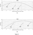
- a first method 100 is shown in Figure 3 , and explained with reference to the accompanying charts in Figures 4 and 5 .
- a second method 200 which may be used independently of the first method 100 or in conjunction with the first method 100, is depicted in Figure 6 and explained with reference to the accompanying chart in Figure 7 .
- the following methods are performed by the wind turbine controller 13 that is connected to and receives inputs from the wind sensors 11 of the turbine and from power output sensors for each RNA 3.
- the wind turbine controller 13 implements the methods and outputs control signals indicating adjustments to be made to the angle of the common yaw system 9 and any other yaw system or relevant control system present in the turbine as required.
- An example schematic of a controller is shown in Figure 8 , and its operation will be described in due course.
- Such a wind turbine controller may be located local to the wind turbine or remote from it.
- the control of a common yaw system 9 to yaw the angle of the RNAs 3 is implemented by operating a yaw motor (not shown).
- the method 100 has a first step 102 of measuring a wind power parameter data for each RNA over a plurality of relative wind directions measured by the wind direction sensor.
- the data gathered in step 102 is used to determine the relative wind direction at which the wind power parameter has a maximum value for each RNA.
- the wind power parameter typically comprises the measured active power output value, e.g. as may be determined by an appropriate power meter installed at the wind turbine, as would be understood by the skilled person.
- the pitch angle may be used as the wind power parameter.
- the wind power parameter data is gathered by measuring both the wind power parameter and the associated wind direction as measured by the wind direction sensor over a predetermined period of time. As the wind direction measured by the sensor changes throughout a period, the data will permit power data to be generated over a plurality of different wind directions. The power distribution relative to wind direction can be determined for each RNA.
- the power distributions may be generated based on data gathered over a predetermined period of time.
- the relative wind direction and wind power parameter are sampled over a period of time.
- the relative wind directions may be binned into bins having a set width. For instance, each bin between two direction limits may be 1 degree wide, 0.1 degree wide, 0.01 degree wide, or any suitable width depending upon the precision of the sensors used. The limits may, for example, be -8 to 8 degrees, or a greater or smaller range may be used.
- the measured wind power parameter in the sample is used to calculate a new average wind power parameter for the bin. This may be calculated using a cumulative moving average.
- step 104 may comprise selecting the bin corresponding to the highest value.
- step 104 may comprise fitting the wind power parameter values for the bins to a curve, and calculating the maximum point on the curve.
- the bin with the highest value may be determined and a curve fitted using either the neighbouring bin values or the raw data used to generate the bin value.
- the distributions may be generated according to one or more thresholds indicating when a sufficient amount of data has been gathered.
- Each wind direction may have an associated threshold. When all thresholds are met for a range of wind directions, the data may be used in the remainder of the method.
- the wind power parameter data may also be collected in predetermined ranges or 'bins' corresponding to percentage ranges of the rated power of the turbine.
- Wind power parameter data is utilised to arrange the data into the bins to ensure that the data is accurate; utilising wind speed for binning is possible but may result in inaccuracies in the data due to aerodynamic effects associated with the RNAs and the positioning of the wind speed sensors relative to the rotors. Binning by wind power parameter level is also useful to allow effects seen at different wind speeds to be observed.
- the air flow through a rotor or the amount of bending of the support structure may be different depending on how fast the wind is and consequently how much power is generated by each RNA. Therefore, it is useful to bin the wind power parameter data to adapt to changing conditions.
- the method below may be applied to determine a control wind direction for each range or bin of the wind power parameters, and a determination made as to which control wind direction is most appropriate for controlling the turbine according to a measured wind power output.
- the power distribution line is illustrated by the solid line, labelled 30a in chart (a) and 30b in chart (b).
- the dashed vertical line, labelled 40a and 40b in charts (a) and (b) respectively, indicates the relative wind direction at which the maximum value of the wind power parameter occurs for the distribution, as determined in step 104.
- the dash-dot vertical line, labelled 50a and 50b in charts (a) and (b) respectively, indicates an example measurement from the wind direction sensor 11 of the RNA 3 of the relative wind direction measured over the same or a similar time period as the power distribution was determined, without any correction according to the present method applied.
- RNA 1 has a maximum power parameter value of approximately 1130 kW when the relative wind direction is -1 degrees as measured by the wind direction sensor.
- the uncorrected measurements of the wind direction sensor 11 indicate that RNA 1 is positioned at +2 degrees to the relative wind direction.
- data collected by the wind direction sensor suggests that the angle of the wind relative to the main direction of the rotor of RNA 1 is +2 degrees, when in fact the point at which maximum power is achieved is -1 degrees.
- the maximum power point is taken to indicate the position at which the wind and the rotor are aligned, i.e. the wind is head-on.
- the above difference in readings by the wind sensors of +2 and -2 degrees may indicate, for example, that the support structure holding each RNA is bending backwards, as shown in Figure 2b .
- a control wind direction is determined based on the data found in step 104.
- the control wind direction is the average wind direction of the determined wind directions at which the wind power parameter has its maximum value.
- the mean of the two maximum values, the lines 40a and 40b in the charts of Figure 4 is calculated and a mean value determined.
- This mean value corresponds to the position at which the wind power parameter is substantially optimised.
- the mean direction corresponds to the point of maximum power parameter for the pair of RNAs. Accordingly, this method works well when both RNAs are performing equally well.
- weightings may be applied to the relative wind directions before averaging in order to achieve a more optimum control wind direction.
- step 106 leads to a control relative wind direction of +1 degrees, as the mean of -1 and +3 degrees.
- the maximum value of the wind power parameter is different for each RNA, it is not possible to achieve the maximum value for one of the RNAs without sacrificing the output of the other. Accordingly, by choosing a mid-point at which the overlap of the power productions is at a maximum or close to a maximum, the power lost due to the positioning of the RNAs is minimised.
- Determining the control wind direction may also include setting a value of the zero relative wind direction, i.e. the direction at which the wind sensors measure zero degrees, to be equal to the determined control wind direction.
- the wind direction sensors may be recalibrated so that a reading of zero degrees is measured when the measured relative wind direction is the control wind direction.
- both RNAs have the same zero relative wind direction, so that their point of maximum is equal distance from the zero relative wind direction. Setting this value also has the advantage that measurements from one of the wind sensors can be used to control the yaw system should there be a fault in the other wind sensor.
- FIG. 5 An implementation of this step on the example of Figure 4 is shown in Figure 5 .
- the wind direction sensors 11 of each RNA have been recalibrated so that the zero relative wind direction is the control wind direction as determined above. That is, that from the data gathered according to steps 102 and 104, a control wind direction was determined and the sensors recalibrated accordingly.
- the control direction was determined as +1 degrees, and both sensors were recalibrated to set this as the zero direction. Accordingly, it can now be seen that the point of maximum wind power parameter in each chart is equally distant from the zero relative wind direction.
- determining the control wind direction may alternatively include setting the value of the zero relative wind direction to reduce the difference between the zero relative wind direction and the determined control wind direction.
- the wind direction sensors may be recalibrated so that a reading of zero degrees is measured at a point that is closer to the control wind direction. For example, if it is determined that the control wind direction at which the maximum wind power parameter value is found is at +6 degrees from where the current zero relative wind direction is, then the zero wind direction may be set at +4 degrees. This provides some room for error in sensor readings, and prevents overshoot during control.
- this also allows for the process to be performed iteratively, so that small incremental changes to the zero wind direction are made rather than larger ones.
- the common yaw control system is controlled based on the determined control wind direction.
- Controlling the common yaw system typically includes operating the yaw system to yaw the RNAs so that the angle of the yaw system is at the control wind direction. This includes comparison of the current yaw angle with the control wind direction and determining an error according to which the yawing can be performed.
- Controlling the yaw control system may also include operating the yaw system to yaw the RNAs when the measured relative wind direction determined by one or more of the wind direction sensors differs from the control relative wind direction. If the sensors are recalibrated so that a zero reading is given when the measured relative wind direction equals the control direction, the control of the yaw system is the normal action of the yaw control system.
- yawing may be restricted to errors greater than a predetermined threshold. For example, yawing may be only performed if the angle between the current yaw angle and the control wind direction is greater than 5 degrees. This avoids unnecessary power usage for small changes in control wind direction.
- the above method ensures that the RNAs are yawed into the wind to maximise measurable parameters, thereby improving the efficiency and output of the entire turbine.
- An alternative method 200 is provided in Figure 6 and explained in relation to Figure 7 .
- the alternative method 200 enables the same output to be determined but in a slightly different way.
- the effect of improving the output and efficiency of the multi-rotor turbine is achieved by both methods 100 and 200.
- the first step 202 is the same as the first step 102 in the method 100. So, at step 202, wind power parameter data for each RNA is gathered over a plurality of wind directions.
- the wind power parameter data for each RNA is combined to provide a single wind power parameter to relative wind direction data set.
- the combined data set is for the two RNAs controlled by the common yaw system.
- this method may be applied to any RNAs forming part of the wind turbine.
- the entire power output of the turbine may be taken into account in this example and the control determined for the entire turbine.
- Wind direction may cause rotor turbulence, which in turn may change the flow of air over one or more rotors of another RNA in the multi-rotor turbine, and thus affect the power output of that RNA. Therefore, it may be useful to ensure that the yaw angle of the RNAs leads to a maximum across all RNAs and not just those controlled by the common yaw system.
- the combined wind power parameter data is achieved by ensuring that the measurements are on a common relative wind direction scale.
- a common relative wind direction scale may be achieved by ensuring that the zero relative wind direction of the wind sensors is the same. This may be achieved by taking an average of the readings of the wind sensors as to what the wind direction is, and then subsequently setting the zero wind direction for the sensors to be equal to this average.
- the wind power parameter values may be summed and assigned a relative wind direction value that is equal to the average of the relative wind direction readings of the sensors.
- the power parameter data sets can be summed to give the overall chart such as the one shown in Figure 7 .
- the data used to generate Figure 7 is the same as the data used in Figure 4 , so it can be seen that the total power, represented by the solid line 60, is approximately equal to the power of RNA 1 and RNA 2 in Figure 4 .
- the point of maximum power can be worked out to be approximately +1 degree.
- a control wind direction can be determined as the point in the overall data or measurement set that the wind power parameter has a maximum value. In Figure 7 , this is the +1 degree point described above and indicated by the dashed line 70.
- the yaw system can be controlled according to this value, as is detailed in step 208.
- Step 208 is the step of controlling the yaw system according to the control wind direction, and this step is the same as step 108.
- FIG 8 illustrates a schematic of a controller 13 for controlling the yaw control system.
- a processor 82 receives the wind power parameter data and the measured relative wind direction data.
- the processor 82 determines the reference wind direction, the zero degree value, according to a method as described herein and provides it to a difference junction 84.
- the difference junction 84 also receives a lowpass filtered, measured relative wind direction. The difference between the zero value and the measured relative wind direction is determined.
- This value, labelled 'YawErr' is the yaw error.
- This yaw error is passed through block 86, which determines if the yaw error is greater than a yaw threshold or limit.
- the controller returns to the passing a new measured relative wind direction through the difference junction 84. If the yaw error is greater than the limit, a control signal is dispatched to a yaw motor to control the motor to yaw the RNAs to reduce the error. The process then resumes.
- the processor 82 may periodically provide updated reference values as per the methods described herein.
Landscapes
- Engineering & Computer Science (AREA)
- Mechanical Engineering (AREA)
- Sustainable Development (AREA)
- General Engineering & Computer Science (AREA)
- Sustainable Energy (AREA)
- Chemical & Material Sciences (AREA)
- Life Sciences & Earth Sciences (AREA)
- Combustion & Propulsion (AREA)
- Artificial Intelligence (AREA)
- Software Systems (AREA)
- Mathematical Physics (AREA)
- Fuzzy Systems (AREA)
- Physics & Mathematics (AREA)
- Evolutionary Computation (AREA)
- Power Engineering (AREA)
- Wind Motors (AREA)
Claims (12)
- Verfahren (100, 200) zum Steuern einer Windkraftanlage mit mehreren Rotoren, die mindestens zwei Rotorgondelbaugruppen (3) aufweist, die durch ein gemeinsames Giersteuerungssystem (9) an einer Trägeranordnung montiert sind und jeweils einen daran montierten Windrichtungssensor (11) aufweisen, der so konfiguriert ist, dass er eine Windrichtung relativ zur Vorwärtsrichtung ihrer Rotorgondelbaugruppe (3) misst, wobei das Verfahren (100, 200) umfasst:Messen (102, 202), für jede Rotorgondelbaugruppe (3), von Windleistungsparameterdaten für die Rotorgondelbaugruppe (3) über eine Vielzahl von Windrichtungen, die vom Windrichtungssensor (11) gemessen werden;entweder, in einer ersten Alternative:Bestimmen (104), für jede Rotorgondelbaugruppe (3), der Windrichtung, bei der der Windleistungsparameter einen Maximalwert aufweist;Bestimmen (106) einer Steuerungswindrichtung als durchschnittliche Windrichtung der bestimmten Windrichtungen, bei der der Windleistungsparameter seinen Maximalwert aufweist;oder, in einer zweiten Alternative:Kombinieren (204) der Windleistungsparameterdaten von jeder Rotorgondelbaugruppe (3), um einen Gesamt-Windleistungsparameterdatensatz für die Rotorgondelbaugruppen (3) über eine Vielzahl gemeinsamer Windrichtungen bereitzustellen;Bestimmen (206), aus dem Gesamt-Messdatensatz, einer Steuerungswindrichtung als Windrichtung, bei der der Windleistungsparameter einen Maximalwert aufweist;Steuern (108, 208) des gemeinsamen Giersteuerungssystems (9) auf Grundlage der bestimmten Steuerungswindrichtung;dadurch gekennzeichnet, dass das Verfahren weiter das Neukalibrieren jedes Windrichtungssensors (11) umfasst, um die Windrichtung, bei der der Windrichtungssensor (11) null Grad misst, als gleich der Steuerungswindrichtung einzustellen oder um die Windrichtung, bei der der Windrichtungssensor (11) null Grad misst, als zwischen der Steuerungswindrichtung und der aktuellen Windrichtung, bei der der Sensor (11) null Grad misst, einzustellen.
- Verfahren (100) nach Anspruch 1 gemäß der ersten Alternative, wobei die durchschnittliche Windrichtung eine mittlere Windrichtung aus den bestimmten Windrichtungen umfasst.
- Verfahren (100) nach Anspruch 1 gemäß der ersten Alternative, wobei die durchschnittliche Windrichtung eine gewichtete mittlere Windrichtung auf Grundlage der bestimmten Windrichtungen umfasst, und wobei das Bestimmen (106) der Steuerungswindrichtung umfasst:Anwenden einer Gewichtung auf die bestimmten Windrichtungen auf Grundlage der relativen Werte des Windleistungsparameters bei diesen Windrichtungen; undBestimmen der mittleren Windrichtung aus den gewichteten bestimmten Windrichtungen.
- Verfahren (200) nach Anspruch 1 gemäß der zweiten Alternative, wobei das Kombinieren (204) der Windleistungsparameterdaten für jeden gemessenen Windleistungsparameterwert und jede relative Windrichtung von den Rotorgondelbaugruppen umfasst:Summieren der Windleistungsparameterwerte; undBestimmen eines Durchschnitts der relativen Windrichtungen.
- Verfahren (200) nach Anspruch 1 gemäß der zweiten Alternative oder Anspruch 4,
wobei die Windkraftanlage (1) mit mehreren Rotoren eine oder mehrere Rotorgondelbaugruppen (3) umfasst, die nicht mit dem gemeinsamen Giersteuerungssystem (9) verbunden sind, und wobei das Kombinieren der Windleistungsparameterdaten das Kombinieren der Daten, die für die Vielzahl von Rotorgondelbaugruppen (3) empfangen werden, die die nicht verbundene Rotorgondelbaugruppe (3) beinhalten, umfasst. - Verfahren (100) nach einem der Ansprüche 1 bis 5, das bei Identifizierung eines Fehlers in einem der Windrichtungssensoren (11) nach der Neukalibrierung das Steuern des gemeinsamen Giersteuerungssystems auf Grundlage von Daten von einem anderen der Windrichtungssensoren umfasst.
- Verfahren (100, 200) nach einem der Ansprüche 1 bis 6, das das Trennen der empfangenen Windleistungsparameterdaten in relative Windrichtungs-Bins gemäß der zugehörigen Windrichtung, wobei jedes Bin einen Bereich relativer Windrichtungen umfasst, das Bestimmen eines durchschnittlichen Windleistungsparameterwerts für jedes Bin und das Auswählen des Bins mit dem höchsten durchschnittlichen Windleistungsparameterwert zur Verwendung beim Bestimmen der Steuerungswindrichtung umfasst.
- Verfahren (100, 200) nach einem der Ansprüche 1 bis 7, das das Trennen der empfangenen Windleistungsparameterdaten in Windleistungsparameterbereiche, in denen jedes Bin einen Bereich von Windleistungsparameterwerten relativ zu einem nominalen Windleistungsparameterwert umfasst, das Bestimmen einer Steuerungswindrichtung für jeden Windleistungsparameterbereich, das Bestimmen des Windleistungsparameterbereichs, in dem die Kraftanlage betrieben wird, und das Steuern des gemeinsamen Giersystems gemäß der Steuerungswindrichtung für diesen Windleistungsparameterbereich umfasst.
- Verfahren (100, 200) nach einem der Ansprüche 1 bis 8, wobei die Windleistungsparameterdaten eine Ausgangsleistung eines Generators der Rotorgondelbaugruppe (3) oder die Blattwinkellast eines oder mehrerer Blätter einer Rotorgondelbaugruppe (3) umfassen.
- Verfahren (100, 200) nach einem der Ansprüche 1 bis 8, wobei das Steuern (108, 208) des gemeinsamen Giersteuerungssystems (9) das Steuern des gemeinsamen Giersteuerungssystems (9) auf Grundlage eines Fehlerwerts zwischen einer gemessenen relativen Windrichtung und entweder der Steuerungswindrichtung oder einer Null-Grad-Windrichtung auf Grundlage der Steuerungswindrichtung umfasst.
- Verfahren (100, 200) nach Anspruch 10, wobei das Steuern (108, 208) des gemeinsamen Giersteuerungssystems (9) auf Grundlage des Fehlerwerts umfasst:Vergleichen des Fehlerwertes mit einem vorbestimmten Fehlerschwellenwert; undBetreiben des Systems (9) so, dass die Rotorgondelbaugruppen (3) gegiert werden, wenn der Fehlerwert größer als der vorbestimmte Fehlerschwellenwert ist.
- Windkraftanlagen-Giersteuerungssystem (13), das einen Giermotor, der so konfiguriert ist, dass er mindestens zwei Rotorgondelbaugruppen (3) giert, und eine Steuereinheit umfasst, die so konfiguriert ist, dass sie das Verfahren (100, 200) nach einem der Ansprüche 1 bis 11 durchführt.
Applications Claiming Priority (2)
| Application Number | Priority Date | Filing Date | Title |
|---|---|---|---|
| DKPA202070700 | 2020-10-23 | ||
| PCT/DK2021/050308 WO2022083835A1 (en) | 2020-10-23 | 2021-10-14 | Multi-rotor wind turbine yaw control |
Publications (3)
| Publication Number | Publication Date |
|---|---|
| EP4232706A1 EP4232706A1 (de) | 2023-08-30 |
| EP4232706B1 true EP4232706B1 (de) | 2024-07-31 |
| EP4232706C0 EP4232706C0 (de) | 2024-07-31 |
Family
ID=81289321
Family Applications (1)
| Application Number | Title | Priority Date | Filing Date |
|---|---|---|---|
| EP21806147.1A Active EP4232706B1 (de) | 2020-10-23 | 2021-10-14 | Giersteuerung einer windturbine mit mehreren rotoren |
Country Status (3)
| Country | Link |
|---|---|
| US (1) | US12270377B2 (de) |
| EP (1) | EP4232706B1 (de) |
| WO (1) | WO2022083835A1 (de) |
Families Citing this family (2)
| Publication number | Priority date | Publication date | Assignee | Title |
|---|---|---|---|---|
| US12270377B2 (en) | 2020-10-23 | 2025-04-08 | Vestas Wind Systems A/S | Multi-rotor wind turbine yaw control |
| CN116838547B (zh) * | 2023-02-23 | 2024-02-23 | 北京金风科创风电设备有限公司 | 多转子风力发电机的监测方法及多转子风力发电机 |
Family Cites Families (35)
| Publication number | Priority date | Publication date | Assignee | Title |
|---|---|---|---|---|
| US20120051939A1 (en) * | 2007-12-28 | 2012-03-01 | Optiwind Corporation | Structure and accelerator platform placement for a wind turbine tower |
| JP4995209B2 (ja) * | 2009-01-05 | 2012-08-08 | 三菱重工業株式会社 | 風力発電装置及び風力発電装置の風向推定方法 |
| DK201070274A (en) * | 2009-10-08 | 2011-04-09 | Vestas Wind Sys As | Control method for a wind turbine |
| US9222466B2 (en) * | 2010-08-13 | 2015-12-29 | Vestas Wind Systems A/S | Wind-power production with reduced power fluctuations |
| US9041240B2 (en) * | 2011-05-02 | 2015-05-26 | Tadashi Ishimine | Wind turbine apparatus |
| US9856859B2 (en) * | 2012-06-26 | 2018-01-02 | Vestas Wind Systems A/S | Wind turbine blade vibration detection and radar calibration |
| CH706971A2 (de) * | 2012-09-10 | 2014-03-14 | Wepfer Technics Ag | Windturbinenanlage. |
| EP3309389B1 (de) | 2014-09-29 | 2019-08-14 | Vestas Wind Systems A/S | Verifizierung von windturbinengondelgierpositionssensor |
| CN107429668B (zh) * | 2015-02-12 | 2019-04-23 | 维斯塔斯风力系统集团公司 | 用于将具有多转子的风力涡轮机系统的结构振动减弱的控制系统 |
| EP3256724B1 (de) * | 2015-02-12 | 2020-09-16 | Vestas Wind Systems A/S | Steuerungssystem mit lokalen und zentralen steuergeräten für windturbinensystem mit mehreren rotoren |
| US10711764B2 (en) * | 2015-02-12 | 2020-07-14 | Vestas Wind Systems A/S | Control system for wind turbine having multiple rotors arranged to control support arm orientation |
| WO2016155740A1 (en) * | 2015-03-30 | 2016-10-06 | Vestas Wind Systems A/S | A wind turbine comprising two or more rotors |
| WO2017084674A1 (en) * | 2015-11-18 | 2017-05-26 | Vestas Wind Systems A/S | Control system and method for wind turbine having multiple rotors |
| US10690116B2 (en) * | 2015-11-20 | 2020-06-23 | Vestas Wind Systems A/S | Multi-rotor turbine arranged for coordinated rotational speeds |
| CN109072867B (zh) * | 2016-02-26 | 2020-10-09 | 维斯塔斯风力系统集团公司 | 具有多个转子的风力涡轮机系统 |
| JP6637793B2 (ja) | 2016-03-04 | 2020-01-29 | 株式会社日立製作所 | 複数の風力発電装置の制御装置、ウィンドファームまたは複数の風力発電装置の制御方法 |
| WO2017178025A1 (en) | 2016-04-14 | 2017-10-19 | Vestas Wind Systems A/S | A multi rotor wind turbine |
| CN109219700B (zh) * | 2016-04-15 | 2020-05-22 | 维斯塔斯风力系统有限公司 | 具有平台的多转子风轮机 |
| EP3459092A1 (de) * | 2016-05-20 | 2019-03-27 | Vestas Wind Systems A/S | Rotierender transformator und induktive kopplung |
| WO2017202945A1 (en) * | 2016-05-26 | 2017-11-30 | Vestas Wind Systems A/S | Wind turbine system with improved stability during shutdown |
| EP3464891B1 (de) * | 2016-06-07 | 2022-01-19 | Vestas Wind Systems A/S | Adaptive steuerung einer windturbine durch erfassung einer leistungsänderung |
| CN109416016B (zh) * | 2016-06-27 | 2021-01-01 | 维斯塔斯风力系统有限公司 | 包括用于在移除机舱期间承载转子的停驻结构的风轮机 |
| CN107869420B (zh) | 2016-09-27 | 2020-08-14 | 远景能源(江苏)有限公司 | 风力涡轮机发电场的风力涡轮机偏航控制方法及系统 |
| WO2018059641A1 (en) * | 2016-09-29 | 2018-04-05 | Vestas Wind Systems A/S | Control method for a wind turbine |
| WO2018157897A1 (en) | 2017-03-01 | 2018-09-07 | Vestas Wind Systems A/S | Yaw system monitor for a multi-rotor wind turbine system |
| JP6746552B2 (ja) | 2017-10-17 | 2020-08-26 | 三菱重工業株式会社 | 風力発電装置 |
| CN111788383B (zh) | 2017-12-20 | 2023-06-27 | 维斯塔斯风力系统集团公司 | 基于约束的多转子风力涡轮机的推力平衡控制 |
| KR102009596B1 (ko) | 2018-02-05 | 2019-10-21 | 두산중공업 주식회사 | 멀티형 풍력 발전기 및 이의 제어 방법 |
| CN112567128A (zh) * | 2018-07-09 | 2021-03-26 | 维斯塔斯风力系统集团公司 | 多转子风力涡轮机功率提升策略 |
| CN114930016B (zh) * | 2019-12-16 | 2025-02-11 | 维斯塔斯风力系统集团公司 | 偏航管理 |
| WO2021139863A1 (en) * | 2020-01-06 | 2021-07-15 | Vestas Wind Systems A/S | Wind turbine oscillation detection |
| EP4118322B1 (de) * | 2020-03-10 | 2025-04-30 | Vestas Wind Systems A/S | Verfahren zur steuerung einer windturbine mit mehreren rotoren |
| US12037982B2 (en) * | 2020-06-12 | 2024-07-16 | Vestas Wind Systems A/S | Toe angle control for multirotor wind turbines |
| US12270377B2 (en) | 2020-10-23 | 2025-04-08 | Vestas Wind Systems A/S | Multi-rotor wind turbine yaw control |
| EP4112919B1 (de) * | 2021-07-01 | 2024-10-09 | Vestas Wind Systems A/S | Steuerung eines mehrkanal-windturbinensystems unter verwendung lokaler mpc-regler |
-
2021
- 2021-10-14 US US18/250,354 patent/US12270377B2/en active Active
- 2021-10-14 EP EP21806147.1A patent/EP4232706B1/de active Active
- 2021-10-14 WO PCT/DK2021/050308 patent/WO2022083835A1/en not_active Ceased
Also Published As
| Publication number | Publication date |
|---|---|
| EP4232706A1 (de) | 2023-08-30 |
| US12270377B2 (en) | 2025-04-08 |
| WO2022083835A1 (en) | 2022-04-28 |
| US20230407839A1 (en) | 2023-12-21 |
| EP4232706C0 (de) | 2024-07-31 |
Similar Documents
| Publication | Publication Date | Title |
|---|---|---|
| EP3807529B1 (de) | Gierselbstkalibrierung für einen windturbinengenerator | |
| US11174838B2 (en) | Control method for a wind turbine | |
| US7244100B2 (en) | Horizontal axis wind turbine and method for controlling horizontal axis wind turbine | |
| EP3645866B1 (de) | Computerimplementiertes verfahren zur neukalibrierung mindestens eines gierwinkels einer windturbine, entsprechendes system, computerimplementiertes verfahren zur windparkoptimierung und entsprechender windpark | |
| CN108496000B (zh) | 用于风力涡轮机的控制方法 | |
| US8702388B2 (en) | Calibration of blade load sensors | |
| CN109312718B (zh) | 风力涡轮机的控制方法 | |
| US11041484B2 (en) | Method for controlling a wind turbine, and associated wind turbine | |
| US20080111379A1 (en) | Wind Turbine and Method for the Automatic Correction of Wind Vane Settings | |
| KR101529805B1 (ko) | 풍력 터빈을 작동하는 방법 | |
| US20190353144A1 (en) | Control method for a wind turbine | |
| EP4232706B1 (de) | Giersteuerung einer windturbine mit mehreren rotoren | |
| US11078884B2 (en) | Determining wind direction offset using yaw events | |
| US20230016798A1 (en) | Device for determining the distance between a wind turbine blade and its wind turbine tower at passing | |
| CN108474348A (zh) | 用于风力涡轮机的控制方法 | |
| CN114303012B (zh) | 低于额定风速时控制风力涡轮机的功率输出 | |
| EP4430298B1 (de) | Verfahren und vorrichtung zur kalibrierung eines giersystems einer windturbine | |
| WO2025186339A8 (fr) | Systeme de supervision d'un parc eolien | |
| US20140161610A1 (en) | Method and device for reducing a pitching moment which loads a rotor of a wind power plant | |
| EP4430299B1 (de) | Verfahren und vorrichtung zur kalibrierung eines giersystems einer windturbine zur verminderung der ermüdung und zur steigerung der leistung | |
| EP4653695A1 (de) | Verfahren zur minderung einer fehlausrichtung einer gondel einer windturbine und windturbine | |
| EP4715201A1 (de) | Azimut-schätzvorrichtung für einen rotor | |
| WO2025108528A1 (en) | Calibrating a wind direction sensor of a wind turbine |
Legal Events
| Date | Code | Title | Description |
|---|---|---|---|
| STAA | Information on the status of an ep patent application or granted ep patent |
Free format text: STATUS: UNKNOWN |
|
| STAA | Information on the status of an ep patent application or granted ep patent |
Free format text: STATUS: THE INTERNATIONAL PUBLICATION HAS BEEN MADE |
|
| PUAI | Public reference made under article 153(3) epc to a published international application that has entered the european phase |
Free format text: ORIGINAL CODE: 0009012 |
|
| STAA | Information on the status of an ep patent application or granted ep patent |
Free format text: STATUS: REQUEST FOR EXAMINATION WAS MADE |
|
| 17P | Request for examination filed |
Effective date: 20230414 |
|
| AK | Designated contracting states |
Kind code of ref document: A1 Designated state(s): AL AT BE BG CH CY CZ DE DK EE ES FI FR GB GR HR HU IE IS IT LI LT LU LV MC MK MT NL NO PL PT RO RS SE SI SK SM TR |
|
| DAV | Request for validation of the european patent (deleted) | ||
| DAX | Request for extension of the european patent (deleted) | ||
| GRAP | Despatch of communication of intention to grant a patent |
Free format text: ORIGINAL CODE: EPIDOSNIGR1 |
|
| STAA | Information on the status of an ep patent application or granted ep patent |
Free format text: STATUS: GRANT OF PATENT IS INTENDED |
|
| INTG | Intention to grant announced |
Effective date: 20240423 |
|
| GRAS | Grant fee paid |
Free format text: ORIGINAL CODE: EPIDOSNIGR3 |
|
| GRAA | (expected) grant |
Free format text: ORIGINAL CODE: 0009210 |
|
| STAA | Information on the status of an ep patent application or granted ep patent |
Free format text: STATUS: THE PATENT HAS BEEN GRANTED |
|
| AK | Designated contracting states |
Kind code of ref document: B1 Designated state(s): AL AT BE BG CH CY CZ DE DK EE ES FI FR GB GR HR HU IE IS IT LI LT LU LV MC MK MT NL NO PL PT RO RS SE SI SK SM TR |
|
| REG | Reference to a national code |
Ref country code: CH Ref legal event code: EP Ref country code: GB Ref legal event code: FG4D |
|
| REG | Reference to a national code |
Ref country code: DE Ref legal event code: R096 Ref document number: 602021016577 Country of ref document: DE |
|
| REG | Reference to a national code |
Ref country code: IE Ref legal event code: FG4D |
|
| U01 | Request for unitary effect filed |
Effective date: 20240731 |
|
| U07 | Unitary effect registered |
Designated state(s): AT BE BG DE DK EE FI FR IT LT LU LV MT NL PT SE SI Effective date: 20240807 |
|
| U20 | Renewal fee for the european patent with unitary effect paid |
Year of fee payment: 4 Effective date: 20241025 |
|
| PG25 | Lapsed in a contracting state [announced via postgrant information from national office to epo] |
Ref country code: NO Free format text: LAPSE BECAUSE OF FAILURE TO SUBMIT A TRANSLATION OF THE DESCRIPTION OR TO PAY THE FEE WITHIN THE PRESCRIBED TIME-LIMIT Effective date: 20241031 |
|
| PG25 | Lapsed in a contracting state [announced via postgrant information from national office to epo] |
Ref country code: GR Free format text: LAPSE BECAUSE OF FAILURE TO SUBMIT A TRANSLATION OF THE DESCRIPTION OR TO PAY THE FEE WITHIN THE PRESCRIBED TIME-LIMIT Effective date: 20241101 Ref country code: PL Free format text: LAPSE BECAUSE OF FAILURE TO SUBMIT A TRANSLATION OF THE DESCRIPTION OR TO PAY THE FEE WITHIN THE PRESCRIBED TIME-LIMIT Effective date: 20240731 |
|
| PG25 | Lapsed in a contracting state [announced via postgrant information from national office to epo] |
Ref country code: IS Free format text: LAPSE BECAUSE OF FAILURE TO SUBMIT A TRANSLATION OF THE DESCRIPTION OR TO PAY THE FEE WITHIN THE PRESCRIBED TIME-LIMIT Effective date: 20241130 |
|
| PG25 | Lapsed in a contracting state [announced via postgrant information from national office to epo] |
Ref country code: HR Free format text: LAPSE BECAUSE OF FAILURE TO SUBMIT A TRANSLATION OF THE DESCRIPTION OR TO PAY THE FEE WITHIN THE PRESCRIBED TIME-LIMIT Effective date: 20240731 |
|
| PG25 | Lapsed in a contracting state [announced via postgrant information from national office to epo] |
Ref country code: ES Free format text: LAPSE BECAUSE OF FAILURE TO SUBMIT A TRANSLATION OF THE DESCRIPTION OR TO PAY THE FEE WITHIN THE PRESCRIBED TIME-LIMIT Effective date: 20240731 Ref country code: RS Free format text: LAPSE BECAUSE OF FAILURE TO SUBMIT A TRANSLATION OF THE DESCRIPTION OR TO PAY THE FEE WITHIN THE PRESCRIBED TIME-LIMIT Effective date: 20241031 |
|
| PG25 | Lapsed in a contracting state [announced via postgrant information from national office to epo] |
Ref country code: RS Free format text: LAPSE BECAUSE OF FAILURE TO SUBMIT A TRANSLATION OF THE DESCRIPTION OR TO PAY THE FEE WITHIN THE PRESCRIBED TIME-LIMIT Effective date: 20241031 Ref country code: PL Free format text: LAPSE BECAUSE OF FAILURE TO SUBMIT A TRANSLATION OF THE DESCRIPTION OR TO PAY THE FEE WITHIN THE PRESCRIBED TIME-LIMIT Effective date: 20240731 Ref country code: NO Free format text: LAPSE BECAUSE OF FAILURE TO SUBMIT A TRANSLATION OF THE DESCRIPTION OR TO PAY THE FEE WITHIN THE PRESCRIBED TIME-LIMIT Effective date: 20241031 Ref country code: IS Free format text: LAPSE BECAUSE OF FAILURE TO SUBMIT A TRANSLATION OF THE DESCRIPTION OR TO PAY THE FEE WITHIN THE PRESCRIBED TIME-LIMIT Effective date: 20241130 Ref country code: HR Free format text: LAPSE BECAUSE OF FAILURE TO SUBMIT A TRANSLATION OF THE DESCRIPTION OR TO PAY THE FEE WITHIN THE PRESCRIBED TIME-LIMIT Effective date: 20240731 Ref country code: GR Free format text: LAPSE BECAUSE OF FAILURE TO SUBMIT A TRANSLATION OF THE DESCRIPTION OR TO PAY THE FEE WITHIN THE PRESCRIBED TIME-LIMIT Effective date: 20241101 Ref country code: ES Free format text: LAPSE BECAUSE OF FAILURE TO SUBMIT A TRANSLATION OF THE DESCRIPTION OR TO PAY THE FEE WITHIN THE PRESCRIBED TIME-LIMIT Effective date: 20240731 |
|
| PG25 | Lapsed in a contracting state [announced via postgrant information from national office to epo] |
Ref country code: SM Free format text: LAPSE BECAUSE OF FAILURE TO SUBMIT A TRANSLATION OF THE DESCRIPTION OR TO PAY THE FEE WITHIN THE PRESCRIBED TIME-LIMIT Effective date: 20240731 |
|
| PG25 | Lapsed in a contracting state [announced via postgrant information from national office to epo] |
Ref country code: CZ Free format text: LAPSE BECAUSE OF FAILURE TO SUBMIT A TRANSLATION OF THE DESCRIPTION OR TO PAY THE FEE WITHIN THE PRESCRIBED TIME-LIMIT Effective date: 20240731 |
|
| PG25 | Lapsed in a contracting state [announced via postgrant information from national office to epo] |
Ref country code: SK Free format text: LAPSE BECAUSE OF FAILURE TO SUBMIT A TRANSLATION OF THE DESCRIPTION OR TO PAY THE FEE WITHIN THE PRESCRIBED TIME-LIMIT Effective date: 20240731 |
|
| REG | Reference to a national code |
Ref country code: CH Ref legal event code: PL |
|
| PLBE | No opposition filed within time limit |
Free format text: ORIGINAL CODE: 0009261 |
|
| STAA | Information on the status of an ep patent application or granted ep patent |
Free format text: STATUS: NO OPPOSITION FILED WITHIN TIME LIMIT |
|
| PG25 | Lapsed in a contracting state [announced via postgrant information from national office to epo] |
Ref country code: MC Free format text: LAPSE BECAUSE OF FAILURE TO SUBMIT A TRANSLATION OF THE DESCRIPTION OR TO PAY THE FEE WITHIN THE PRESCRIBED TIME-LIMIT Effective date: 20240731 |
|
| 26N | No opposition filed |
Effective date: 20250501 |
|
| PG25 | Lapsed in a contracting state [announced via postgrant information from national office to epo] |
Ref country code: CH Free format text: LAPSE BECAUSE OF NON-PAYMENT OF DUE FEES Effective date: 20241031 |
|
| PG25 | Lapsed in a contracting state [announced via postgrant information from national office to epo] |
Ref country code: IE Free format text: LAPSE BECAUSE OF NON-PAYMENT OF DUE FEES Effective date: 20241014 |
|
| PG25 | Lapsed in a contracting state [announced via postgrant information from national office to epo] |
Ref country code: RO Free format text: LAPSE BECAUSE OF FAILURE TO SUBMIT A TRANSLATION OF THE DESCRIPTION OR TO PAY THE FEE WITHIN THE PRESCRIBED TIME-LIMIT Effective date: 20240731 |
|
| U20 | Renewal fee for the european patent with unitary effect paid |
Year of fee payment: 5 Effective date: 20251027 |
|
| PG25 | Lapsed in a contracting state [announced via postgrant information from national office to epo] |
Ref country code: CY Free format text: LAPSE BECAUSE OF FAILURE TO SUBMIT A TRANSLATION OF THE DESCRIPTION OR TO PAY THE FEE WITHIN THE PRESCRIBED TIME-LIMIT; INVALID AB INITIO Effective date: 20211014 |
|
| PG25 | Lapsed in a contracting state [announced via postgrant information from national office to epo] |
Ref country code: HU Free format text: LAPSE BECAUSE OF FAILURE TO SUBMIT A TRANSLATION OF THE DESCRIPTION OR TO PAY THE FEE WITHIN THE PRESCRIBED TIME-LIMIT; INVALID AB INITIO Effective date: 20211014 |