EP4232736B1 - Connecteur rapide avec vérification et contrôle d'assemblage - Google Patents
Connecteur rapide avec vérification et contrôle d'assemblage Download PDFInfo
- Publication number
- EP4232736B1 EP4232736B1 EP22705149.7A EP22705149A EP4232736B1 EP 4232736 B1 EP4232736 B1 EP 4232736B1 EP 22705149 A EP22705149 A EP 22705149A EP 4232736 B1 EP4232736 B1 EP 4232736B1
- Authority
- EP
- European Patent Office
- Prior art keywords
- assembly
- quick connector
- connector
- shielding portion
- connector body
- Prior art date
- Legal status (The legal status is an assumption and is not a legal conclusion. Google has not performed a legal analysis and makes no representation as to the accuracy of the status listed.)
- Active
Links
Images




Classifications
-
- F—MECHANICAL ENGINEERING; LIGHTING; HEATING; WEAPONS; BLASTING
- F16—ENGINEERING ELEMENTS AND UNITS; GENERAL MEASURES FOR PRODUCING AND MAINTAINING EFFECTIVE FUNCTIONING OF MACHINES OR INSTALLATIONS; THERMAL INSULATION IN GENERAL
- F16L—PIPES; JOINTS OR FITTINGS FOR PIPES; SUPPORTS FOR PIPES, CABLES OR PROTECTIVE TUBING; MEANS FOR THERMAL INSULATION IN GENERAL
- F16L37/00—Couplings of the quick-acting type
- F16L37/08—Couplings of the quick-acting type in which the connection between abutting or axially overlapping ends is maintained by locking members
- F16L37/084—Couplings of the quick-acting type in which the connection between abutting or axially overlapping ends is maintained by locking members combined with automatic locking
- F16L37/098—Couplings of the quick-acting type in which the connection between abutting or axially overlapping ends is maintained by locking members combined with automatic locking by means of flexible hooks
- F16L37/0985—Couplings of the quick-acting type in which the connection between abutting or axially overlapping ends is maintained by locking members combined with automatic locking by means of flexible hooks the flexible hook extending radially inwardly from an outer part and engaging a bead, recess or the like on an inner part
-
- F—MECHANICAL ENGINEERING; LIGHTING; HEATING; WEAPONS; BLASTING
- F16—ENGINEERING ELEMENTS AND UNITS; GENERAL MEASURES FOR PRODUCING AND MAINTAINING EFFECTIVE FUNCTIONING OF MACHINES OR INSTALLATIONS; THERMAL INSULATION IN GENERAL
- F16L—PIPES; JOINTS OR FITTINGS FOR PIPES; SUPPORTS FOR PIPES, CABLES OR PROTECTIVE TUBING; MEANS FOR THERMAL INSULATION IN GENERAL
- F16L2201/00—Special arrangements for pipe couplings
- F16L2201/10—Indicators for correct coupling
Definitions
- the present invention relates to connector assemblies to join fluid lines together, and in particular, connector assemblies providing machine readable connection verification.
- Quick connectors are often used in the automotive industry to provide a fluid connection between two components.
- Quick connectors function by joining the connector to a male fitting, the male fitting optionally being in conformance with SAE J2044.
- known quick connectors engage a raised annular bead on the male fitting, thereby preventing withdrawal of the male fitting.
- Quick connectors can be used to connect fuel lines, fuel vapor lines, fuel tank filler necks, and in-tank fuel applications, to name but a few applications, and must adhere to stringent engineering requirements, particularly for automotive applications.
- Quick connectors sometimes include a pre-installed assembly check to provide visual verification that the male fitting has engaged the quick connector.
- the pre-installed assembly check retracts from the quick connector when the male fitting is engaged. When in the retracted position, the assembly check can be manually removed from the quick connector and discarded. In some applications, however, the pre-installed assembly check can become dislodged from the quick connector during shipment, preventing use of the quick connector by the vehicle manufacturer. Accordingly, there remains a continued need for an improved quick connector having an assembly check. In particular, there remains a continued need for an improved quick connector having a separate assembly check that can be readily assembled to the quick connector by the manufacturer for providing visual confirmation of a secure connection.
- the document JP 2009 024800 A discloses a quick connector.
- EP3736481A1 discloses a quick connector assembly with a verification tab.
- the quick connector includes an assembly check that is partially received within an input end of a quick connector.
- the assembly check is separate from the quick connector and includes a pull tab and a shielding portion.
- the assembly check retracts from the input end of the quick connector and can be manually removed via the pull tab.
- a machine readable verification indicia can be read. The verification indicia is visible on an underside of the shielding portion or visible on the quick connector once the shielding portion is removed.
- the quick connector includes a connector body and one-button or two-button sliding lock latch.
- the connector body defines a fluid passage between a fluid input end and a fluid output end and defines a transverse opening proximate the fluid input end.
- the sliding lock latch is housed within the transverse opening.
- the assembly check is partially received within the input end of the connector body and includes a pull tab and a shielding portion.
- the shielding portion is optionally a rectangular element and extends orthogonal to the pull tab. Further optionally, the shielding portion can include a locking tab on a distal end thereof for engaging a collar portion of the connector body.
- the underside of the shielding portion includes a visual indicia, optionally a machine readable visual indicia, and further optionally a QR code or a bar code.
- the assembly check does not include a verification indicia but extends over a verification indicia on the connector body to conceal the verification indicia from view.
- the assembly check retracts from the input end of the connector body and can be manually removed via the pull tab. Once removed, the verification indicia is visible on the connector body.
- the shielding portion is optionally a rectangular element and extends orthogonal to the pull tab.
- the shielding portion can include a locking tab on a distal end thereof for engaging a collar portion of the connector body.
- the verification indicia is optionally a machine readable verification indicia, and further optionally a QR code or a bar code.
- the quick connector assembly 10 includes a quick connector 12 and an assembly check 14, the assembly check 14 being separate from the quick connector 12.
- the assembly check 14 Upon insertion of a male connector 100 within the input end of the quick connector 12, the assembly check 14 retracts from the input end of the quick connector 12 and can be manually removed via a pull tab 16. Once removed from the quick connector 12, a machine readable verification indicia can be read.
- Each such feature of the quick connector assembly 10 is separately discussed below. Though primarily described below in connection with fuel lines, the quick connector assembly 10 can be used in other applications as desired, including the connection of brake lines and coolant lines for example.
- the quick connector 12 includes a connector body 15 and an optional sliding lock latch 18.
- the connector body 15 defines a fluid passage between an input end 20 and an output end 22.
- the terms "input end” and “output end” are recited for clarity and are not intended to be limiting, as the moving fluid (e.g., fuel, oil, coolant) may move in the opposite direction in some applications.
- the connector body 15 further includes an enlarged connector collar 24 at the input end 20 and a barbed stem 26 and the output end 22.
- the connector body 15 comprises a straight coupling in the illustrated embodiment. In other embodiments the connector body 15 can comprise an angled coupling between two fluid lines.
- the connector body 15 can comprise an elbow fitting, such that the fluid passage includes an approximately ninety-degree bend between the input end 20 and the output end 22.
- the connector body 15 can be formed from any suitable material, optionally a durable, chemical-resistant and lightweight polymerized material.
- the connector collar 24 includes a sidewall 28 that defines a transverse opening 30.
- the transverse opening 30 is shaped to receive the sliding lock latch 18.
- the sliding lock latch 18 includes a two-button sliding lock latch in the illustrated embodiment, while other configurations can be used in other embodiments, including a single-button sliding lock latch.
- the sliding lock latch 18 of Figure 2 comprises a flexible retainer having a pair of externally accessible buttons 32.
- the externally accessible buttons 32 are connected to a pair of laterally moveable snap-fit barbs 34 by diagonal bridging arms 36.
- Each snap fit barb 34 is arcuate when viewed from an end, and is also tapered with a greater diameter closest to the female end.
- the snap-fit barbs 34 prevent removal of the male connector 100 from the quick connector 12.
- an operator depresses the opposing buttons 32 toward an axial centerline of the quick connector body 15 while pulling out the male connector 100. Inward movement of the buttons 32 serves to laterally expand the barbs 34 away from the centerline.
- alternate configurations of quick connectors can be used in other embodiments, including dual-latch and single-latch quick connectors for example.
- the connector body 15 houses a primary O-ring 40, a spacer 42, a secondary O-ring 44, and a seal lock washer 46, each being visible in cross-section in Figure 3 .
- the primary O-ring 40, the spacer 42, the secondary O-ring 44, and the seal lock washer 46 provide a seal arrangement, however a seal arrangement is not required and other seal arrangements can be used in other embodiments.
- the assembly check 14 includes the above pull tab 16 in combination with a body portion 50 and a shielding portion 60.
- the body portion 50 includes a C-shaped flange 52 that partially surrounds the opening at the input end 20 of the connector body 15.
- the C-shaped flange 52 includes first and second terminal portions 53 that are spaced apart from each other by a distance at least equal to the outer diameter of the male fitting 100, such that the C-shaped flange 52 can be removed from the male fitting 100 by pulling on the pull tab 16.
- the body portion 50 also includes first and second locking tabs 54, 56 and first and second retention tabs 66, 68.
- the first locking tab 54 and the first retention tab 66 comprise a first S-shaped element that is rotatably supported by adjacent mounting arms 58, the mounting arms protruding from an axial projection 62.
- the second locking tab 56 and the second retention tab 68 comprise a second S-shaped element that is rotatably supported by adjacent mounting arms 58.
- the locking tabs 54, 56 extend radially inward
- the retention tabs 66, 68 extend radially outward.
- the assembly check 14 can be integrally formed from any suitable material, for example a thermoplastic resin, optionally a nylon resin, such that the mounting arms 58, the locking tabs 54, 56, and the retention tabs 66, 68 are integrally joined to each other.
- Each locking tab 54, 56 includes a ramped engagement surface 64 for deflecting the locking tab 54, 56 when engaged by the raised annular bead 102 of a male fitting 100.
- Each engagement surface 64 is arcuate when viewed from an end, and is also tapered with a greater diameter closest to the input end.
- the raised annular bead 102 causes rotation of the locking tabs 54, 56 via torsion of the mounting arms 58.
- Rotation of the locking tabs 54, 56 causes rotation of the retention tabs 66, 68 via a see-saw action.
- Rotation of the retention tabs 66, 68 releases the retention tabs 66, 68 from their engagement with the inner annular surface of the quick connector collar 24.
- the retention tabs 66, 68 no longer engage the quick connector collar 24, and the assembly check 14 moves against the direction of the male fitting 100, away from the opening at the input end 20 of the connector body 15.
- the shielding portion 60 extends orthogonally from the pull tab 16.
- the shielding portion 60 is rectangular, being generally coextensive with the quick connector collar 24 and vertically offset from the collar 24.
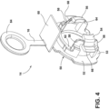
- the underside of the shielding portion 60 includes a verification indicia 70.
- the verification indicia 70 is applied to the collar 24, rather than to the shielding portion 60.
- the verification indicia 70 comprises a visual cue to indicate that the quick connector 12 is fully seated over a male fitting 100.
- the verification indicia 70 can include for example a one-dimensional barcode (e.g.
- UPC code UPC code, EAN code, code 39, code 128, ITF, code 93, codabar, GS1 databar, MSI Plessey, etc.
- a two-dimensional barcode e.g. QR code, datamatrix code, PDF417, AZTEC, etc.
- a holographic code e.g. QR code, datamatrix code, PDF417, AZTEC, etc.
- a human-readable alpha-numeric code e.g. QR code, datamatrix code, PDF417, AZTEC, etc.
- holographic code e.g. QR code, datamatrix code, PDF417, AZTEC, etc.
- a human-readable alpha-numeric code e.g., a human-readable alpha-numeric code, or other codes, whether known or hereinafter developed, that are interpretable by machine or human.
- the indicia 70 is not machine readable and includes a color, a pattern, an
- the assembly check 14 pops out from the quick connector 12 when the quick connector is fully inserted over a male fitting 100, generally shown in Figure 6 .
- the raised annular bead 102 causes rotation of the locking tabs 54, 56, which causes rotation of the retention tabs 66, 68.
- Rotation of the retention tabs 66, 68 releases the retention tabs 66, 68 from their engagement with the inner annular surface of the quick connector collar 24, and the assembly check 14 moves against the direction of the male fitting 100, away from the opening at the input end 20 of the connector body 15.
- the operator then pulls the assembly check 14 vertically, e.g., in the direction of the pull tab 16.
- the assembly check 14 is not part of the final assembly, however the operator can scan the verification indicia 70 to confirm assembly of the quick connector 12 onto the male fitting 100.
- the verification is printed on, or supported by, the quick connector collar 24, for example as shown in Figure 7 , such that the verification indicia becomes visible only after removal of the assembly check 14.
- the shielding portion 60 can extend beyond the collar 24 and can include at least one ramped projection 80.
- the ramped projection 80 extends downwardly from the distal edge of the rectangular shielding portion 60, farthest from the pull tab 16.
- the ramped projection 80 includes a flat surface 81 that extends perpendicular to the shielding portion 60.
- the flat surface 81 abuts a rearward-facing surface 82 of the quick connector collar 24 to prevent accidental removal of the assembly check 14.
- the pull tab 16 can rotate relative to the shielding portion 60 (clockwise in the illustrated views). In this respect, the body 50 of the assembly check 14 can retract from the input end of the quick connector 12 while the shielding portion 60 remains in position over the quick connector collar 24.
- the ramped projection 82 improves retention of the assembly check 14 to the quick connector 12.
- the verification indicia 70 is applied directly to the underside of the shielding portion 60 (as in Figures 4-5 ) or to the quick connector collar 24 (as in Figure 7 ). The verification indicia 70 becomes visible only after the shielding portion 60 is removed from the collar 24, which is performed by pulling on the pull tab 16.
- the embodiments discussed above include an assembly check 14 that is partially received within an input end of a quick connector 12.
- the assembly check 14 has broad versatility and can be shipped separately from the quick connector 12 or pre-installed within the input end of the quick connector 12 (e.g., shipped as shown in Figure 1 ).
- the assembly check 14 retracts from the input end of the quick connector 12 (e.g., as shown in Figure 6 ) and can be manually removed via the pull tab 16, which can terminate in a loop or an eyelet 84 for gripping and removal.
- a verification indicia 70 can be read.
- the verification indicia 70 is visible on an underside of the shielding portion 60 or visible on the quick connector collar 24.
- the shielding portion 60 protects the verification indicia 70 from being scanned accidentally before final assembly is complete. Once the verification indicia 70 is visible, the operator can scan the bar code (or other indicia) to verify a secure attachment of the quick connector 12 to the male connector 100, for example a fuel line.
- the quick connector 12 and assembly check 14 can be used in other applications as desired, including the connection of brake lines and coolant lines for example.
- any individual element(s) of the described invention may be replaced by alternative elements that provide substantially similar functionality or otherwise provide adequate operation.
- the disclosed embodiments include a plurality of features that are described in concert and that might cooperatively provide a collection of benefits.
Landscapes
- Engineering & Computer Science (AREA)
- General Engineering & Computer Science (AREA)
- Mechanical Engineering (AREA)
- Quick-Acting Or Multi-Walled Pipe Joints (AREA)
Claims (7)
- Assemblage de connecteur rapide (10) comprenant :un corps de connecteur (15) définissant un passage de fluide entre une première extrémité (20) et une seconde extrémité (22), le corps de connecteur (15) comportant un collier (24) à proximité de la première extrémité (20) ;un contrôle d'assemblage (14) qui est partiellement reçu à l'intérieur de la première extrémité (20) du corps de connecteur (15), le contrôle d'assemblage (14) comportant une languette de traction (16) et une partie de blindage (60), la partie de blindage (60) s'étendant sur au moins une partie du collier (24) du corps de connecteur (15) ; etle connecteur rapide est caractérisé en ce qu'il comprend en outre un indice de vérification (70) sur une face inférieure de la partie de blindage (60) ou sur une surface extérieure du collier (24) sous la partie de blindage (60), dans lequel, lors de l'insertion d'un connecteur mâle (100) dans la première extrémité (20) du corps de connecteur (15), le contrôle d'assemblage (14) se rétracte du corps de connecteur (15) et peut être retiré manuellement par la languette de traction (16), de telle sorte que l'indice de vérification (70) devienne visible.
- Assemblage de connecteur rapide (10) selon la revendication 1, dans lequel l'indice de vérification (70) est lisible par une machine et comporte un code QR, un code à barres, ou un code holographique.
- Assemblage de connecteur rapide (10) selon la revendication 1, dans lequel la partie de blindage (60) comporte une languette faisant saillie vers le bas à partir d'une extrémité distale de la partie de blindage (60) pour s'engager dans le corps du connecteur (15).
- Assemblage de connecteur rapide (10) selon la revendication 1, dans lequel la partie de blindage (60) est un élément rectangulaire qui s'étend orthogonalement à la languette de traction (16).
- Assemblage de connecteur rapide (10) selon la revendication 1, dans lequel :le contrôle de l'assemblage (14) comporte une première et une seconde languette de verrouillage (54, 56) qui s'étendent radialement vers l'intérieur ;le contrôle de l'assemblage (14) comporte une première et une seconde languettes de rétention (66, 68) qui s'étendent radialement vers l'extérieur ;la première languette de rétention (66) tourne à l'unisson avec la première languette de verrouillage (54) ; etla seconde languette de rétention (68) tourne à l'unisson avec la seconde languette de verrouillage (56).
- Assemblage de connecteur rapide (10) selon la revendication 5, dans lequel les première et seconde languettes de verrouillage (54, 56) comportent une surface d'engagement inclinée (64) définissant un diamètre maximum plus proche de la première extrémité (20) du corps du connecteur (15).
- Assemblage de connecteur rapide (10) selon la revendication 1, dans lequel le contrôle d'assemblage (14) comporte une bride en forme de C (52) ayant une première et une seconde partie terminale (53) qui sont espacées l'une de l'autre.
Applications Claiming Priority (2)
| Application Number | Priority Date | Filing Date | Title |
|---|---|---|---|
| US202163148712P | 2021-02-12 | 2021-02-12 | |
| PCT/IB2022/051174 WO2022172176A1 (fr) | 2021-02-12 | 2022-02-09 | Connecteur rapide avec vérification et contrôle d'assemblage |
Publications (2)
| Publication Number | Publication Date |
|---|---|
| EP4232736A1 EP4232736A1 (fr) | 2023-08-30 |
| EP4232736B1 true EP4232736B1 (fr) | 2025-06-11 |
Family
ID=80786787
Family Applications (1)
| Application Number | Title | Priority Date | Filing Date |
|---|---|---|---|
| EP22705149.7A Active EP4232736B1 (fr) | 2021-02-12 | 2022-02-09 | Connecteur rapide avec vérification et contrôle d'assemblage |
Country Status (4)
| Country | Link |
|---|---|
| US (1) | US11873931B2 (fr) |
| EP (1) | EP4232736B1 (fr) |
| CN (1) | CN116685795B (fr) |
| WO (1) | WO2022172176A1 (fr) |
Families Citing this family (2)
| Publication number | Priority date | Publication date | Assignee | Title |
|---|---|---|---|---|
| US12281738B2 (en) * | 2021-08-18 | 2025-04-22 | Cooper-Standard Automotive Inc. | Quick connector with verifier |
| EP4368867B1 (fr) | 2022-11-14 | 2025-10-29 | Oetiker NY, Inc. | Dispositif de vérification pour un ensemble de raccordement de fluide |
Family Cites Families (21)
| Publication number | Priority date | Publication date | Assignee | Title |
|---|---|---|---|---|
| US5152555A (en) | 1991-03-26 | 1992-10-06 | Itt Corporation | Quick connect insertion indicator clip |
| US5897145A (en) * | 1996-12-05 | 1999-04-27 | Tokai Rubber Industries, Ltd. | Connector |
| JP4462671B2 (ja) | 1998-09-17 | 2010-05-12 | 株式会社東郷製作所 | 管継手 |
| EP1536175A3 (fr) * | 1999-09-13 | 2005-10-19 | Swagelok Company | Raccord pourvu d'un dispositif indicateur |
| JP4211486B2 (ja) | 2002-05-23 | 2009-01-21 | 東海ゴム工業株式会社 | クイックコネクタ |
| SE0303016L (sv) * | 2003-11-14 | 2005-04-12 | Aba Sweden Ab | Anordning för hopkoppling av två styva rörformiga föremål |
| US7128347B2 (en) * | 2004-11-18 | 2006-10-31 | Ti Group Automotive Systems, Llc | Passive transmitter for a quick connector |
| US7497477B2 (en) * | 2005-06-15 | 2009-03-03 | Ti Group Automotive Systems, Llc | Pull tab verifier assembly for quick connectors |
| US9016729B2 (en) | 2005-12-06 | 2015-04-28 | Sumitomo Riko Company Limited | Quick connector and checker |
| DE202006005618U1 (de) * | 2006-04-06 | 2006-06-22 | Rehau Ag + Co. | System zur Feststellung von Information an einem Anschluss |
| US7731245B2 (en) | 2006-10-06 | 2010-06-08 | Ti Group Automotive Systems, Llc | Quick connector coupling |
| JP5318379B2 (ja) | 2007-07-20 | 2013-10-16 | 三桜工業株式会社 | クイックコネクタ |
| EP2715204A2 (fr) | 2011-06-02 | 2014-04-09 | A. Raymond et Cie | Raccords fabriqués par impression en trois dimensions |
| US20160025252A1 (en) * | 2014-07-23 | 2016-01-28 | Paccar Inc | Quick fitting connector |
| CN104295836B (zh) | 2014-11-06 | 2016-03-02 | 重庆溯联汽车零部件有限公司 | 一种用于汽车管路系统带防错、确认功能的快换接头 |
| CN204083601U (zh) | 2014-11-06 | 2015-01-07 | 重庆溯联汽车零部件有限公司 | 一种用于汽车管路系统带防错、确认功能的快换接头 |
| US11199281B2 (en) | 2018-01-31 | 2021-12-14 | A. Raymond Et Cie. | Dual-latch quick connector |
| US20200116278A1 (en) * | 2018-10-16 | 2020-04-16 | TB Services, LLC | Pipeline Installation System |
| DE102018219440A1 (de) * | 2018-11-14 | 2020-05-14 | Fränkische Industrial Pipes GmbH & Co. KG | Verbindungseinheit |
| JP6877775B2 (ja) * | 2019-03-01 | 2021-05-26 | 井上スダレ株式会社 | 管継手 |
| EP3736481B1 (fr) | 2019-05-07 | 2022-01-19 | A. Raymond et Cie | Ensemble connecteur rapide avec languette de vérification |
-
2022
- 2022-02-09 EP EP22705149.7A patent/EP4232736B1/fr active Active
- 2022-02-09 CN CN202280008038.6A patent/CN116685795B/zh active Active
- 2022-02-09 WO PCT/IB2022/051174 patent/WO2022172176A1/fr not_active Ceased
- 2022-02-09 US US18/031,930 patent/US11873931B2/en active Active
Also Published As
| Publication number | Publication date |
|---|---|
| WO2022172176A1 (fr) | 2022-08-18 |
| US11873931B2 (en) | 2024-01-16 |
| EP4232736A1 (fr) | 2023-08-30 |
| CN116685795B (zh) | 2026-02-13 |
| CN116685795A (zh) | 2023-09-01 |
| US20230408012A1 (en) | 2023-12-21 |
Similar Documents
| Publication | Publication Date | Title |
|---|---|---|
| EP4232736B1 (fr) | Connecteur rapide avec vérification et contrôle d'assemblage | |
| CN116635661B (zh) | 用于快速连接器的代码验证套筒 | |
| EP2503648B1 (fr) | Dispositif d'assurance de position de connecteur | |
| US6676171B2 (en) | Insertion verifier dust cap | |
| CN107061897B (zh) | 带有自动连接的安全管接头 | |
| JP4937426B1 (ja) | クイックコネクタ | |
| US7390029B2 (en) | Quick connector | |
| US6722703B2 (en) | Quick connector with function of verifying complete connection | |
| US7690694B2 (en) | Quick coupling device | |
| US8336919B2 (en) | Snap-on coupling for connecting a fluid pipe to a rigid end fitting with a connection indicator and method of inspecting this connection | |
| CN103238255B (zh) | 连接器组件 | |
| CN117015676A (zh) | 具有验证功能的快速连接器 | |
| JP2025505850A (ja) | 確認付クイックコネクタ | |
| CN101321981A (zh) | 快速连接器和检验装置 | |
| WO2014097809A1 (fr) | Structure de raccordement de canalisations | |
| KR20120036759A (ko) | 유체 연결용 연결 요소 | |
| EP4249785A1 (fr) | Raccord rapide | |
| US5249830A (en) | Device for locking two coaxial tubes | |
| US20090302600A1 (en) | metal coupling with locked position | |
| JP2025536440A (ja) | 視覚ロックインジケータを備える管状継手 | |
| CN120650550A (zh) | 用于选择性地显示标记的具有可移动环状件的连接器 | |
| JP6989167B1 (ja) | スナップフィット係合コネクタ | |
| CN114382756A (zh) | 用于介质引导管路的插塞连接器 | |
| JP3693108B2 (ja) | コネクタ用半嵌合防止クリップ | |
| JP2024505572A (ja) | データ行列を有する流体ラインクイックコネクタ |
Legal Events
| Date | Code | Title | Description |
|---|---|---|---|
| STAA | Information on the status of an ep patent application or granted ep patent |
Free format text: STATUS: UNKNOWN |
|
| STAA | Information on the status of an ep patent application or granted ep patent |
Free format text: STATUS: THE INTERNATIONAL PUBLICATION HAS BEEN MADE |
|
| PUAI | Public reference made under article 153(3) epc to a published international application that has entered the european phase |
Free format text: ORIGINAL CODE: 0009012 |
|
| STAA | Information on the status of an ep patent application or granted ep patent |
Free format text: STATUS: REQUEST FOR EXAMINATION WAS MADE |
|
| 17P | Request for examination filed |
Effective date: 20230526 |
|
| AK | Designated contracting states |
Kind code of ref document: A1 Designated state(s): AL AT BE BG CH CY CZ DE DK EE ES FI FR GB GR HR HU IE IS IT LI LT LU LV MC MK MT NL NO PL PT RO RS SE SI SK SM TR |
|
| DAV | Request for validation of the european patent (deleted) | ||
| DAX | Request for extension of the european patent (deleted) | ||
| GRAP | Despatch of communication of intention to grant a patent |
Free format text: ORIGINAL CODE: EPIDOSNIGR1 |
|
| STAA | Information on the status of an ep patent application or granted ep patent |
Free format text: STATUS: GRANT OF PATENT IS INTENDED |
|
| INTG | Intention to grant announced |
Effective date: 20250122 |
|
| GRAS | Grant fee paid |
Free format text: ORIGINAL CODE: EPIDOSNIGR3 |
|
| GRAA | (expected) grant |
Free format text: ORIGINAL CODE: 0009210 |
|
| STAA | Information on the status of an ep patent application or granted ep patent |
Free format text: STATUS: THE PATENT HAS BEEN GRANTED |
|
| AK | Designated contracting states |
Kind code of ref document: B1 Designated state(s): AL AT BE BG CH CY CZ DE DK EE ES FI FR GB GR HR HU IE IS IT LI LT LU LV MC MK MT NL NO PL PT RO RS SE SI SK SM TR |
|
| REG | Reference to a national code |
Ref country code: GB Ref legal event code: FG4D |
|
| REG | Reference to a national code |
Ref country code: CH Ref legal event code: EP |
|
| REG | Reference to a national code |
Ref country code: DE Ref legal event code: R096 Ref document number: 602022015799 Country of ref document: DE |
|
| REG | Reference to a national code |
Ref country code: IE Ref legal event code: FG4D |
|
| PG25 | Lapsed in a contracting state [announced via postgrant information from national office to epo] |
Ref country code: FI Free format text: LAPSE BECAUSE OF FAILURE TO SUBMIT A TRANSLATION OF THE DESCRIPTION OR TO PAY THE FEE WITHIN THE PRESCRIBED TIME-LIMIT Effective date: 20250611 Ref country code: ES Free format text: LAPSE BECAUSE OF FAILURE TO SUBMIT A TRANSLATION OF THE DESCRIPTION OR TO PAY THE FEE WITHIN THE PRESCRIBED TIME-LIMIT Effective date: 20250611 |
|
| REG | Reference to a national code |
Ref country code: LT Ref legal event code: MG9D |
|
| PG25 | Lapsed in a contracting state [announced via postgrant information from national office to epo] |
Ref country code: NO Free format text: LAPSE BECAUSE OF FAILURE TO SUBMIT A TRANSLATION OF THE DESCRIPTION OR TO PAY THE FEE WITHIN THE PRESCRIBED TIME-LIMIT Effective date: 20250911 Ref country code: GR Free format text: LAPSE BECAUSE OF FAILURE TO SUBMIT A TRANSLATION OF THE DESCRIPTION OR TO PAY THE FEE WITHIN THE PRESCRIBED TIME-LIMIT Effective date: 20250912 |
|
| REG | Reference to a national code |
Ref country code: NL Ref legal event code: MP Effective date: 20250611 |
|
| PG25 | Lapsed in a contracting state [announced via postgrant information from national office to epo] |
Ref country code: BG Free format text: LAPSE BECAUSE OF FAILURE TO SUBMIT A TRANSLATION OF THE DESCRIPTION OR TO PAY THE FEE WITHIN THE PRESCRIBED TIME-LIMIT Effective date: 20250611 |
|
| PG25 | Lapsed in a contracting state [announced via postgrant information from national office to epo] |
Ref country code: HR Free format text: LAPSE BECAUSE OF FAILURE TO SUBMIT A TRANSLATION OF THE DESCRIPTION OR TO PAY THE FEE WITHIN THE PRESCRIBED TIME-LIMIT Effective date: 20250611 |
|
| PG25 | Lapsed in a contracting state [announced via postgrant information from national office to epo] |
Ref country code: RS Free format text: LAPSE BECAUSE OF FAILURE TO SUBMIT A TRANSLATION OF THE DESCRIPTION OR TO PAY THE FEE WITHIN THE PRESCRIBED TIME-LIMIT Effective date: 20250911 |
|
| PG25 | Lapsed in a contracting state [announced via postgrant information from national office to epo] |
Ref country code: LV Free format text: LAPSE BECAUSE OF FAILURE TO SUBMIT A TRANSLATION OF THE DESCRIPTION OR TO PAY THE FEE WITHIN THE PRESCRIBED TIME-LIMIT Effective date: 20250611 |
|
| PG25 | Lapsed in a contracting state [announced via postgrant information from national office to epo] |
Ref country code: NL Free format text: LAPSE BECAUSE OF FAILURE TO SUBMIT A TRANSLATION OF THE DESCRIPTION OR TO PAY THE FEE WITHIN THE PRESCRIBED TIME-LIMIT Effective date: 20250611 |
|
| PG25 | Lapsed in a contracting state [announced via postgrant information from national office to epo] |
Ref country code: PT Free format text: LAPSE BECAUSE OF FAILURE TO SUBMIT A TRANSLATION OF THE DESCRIPTION OR TO PAY THE FEE WITHIN THE PRESCRIBED TIME-LIMIT Effective date: 20251013 |
|
| REG | Reference to a national code |
Ref country code: AT Ref legal event code: MK05 Ref document number: 1802507 Country of ref document: AT Kind code of ref document: T Effective date: 20250611 |
|
| PG25 | Lapsed in a contracting state [announced via postgrant information from national office to epo] |
Ref country code: IS Free format text: LAPSE BECAUSE OF FAILURE TO SUBMIT A TRANSLATION OF THE DESCRIPTION OR TO PAY THE FEE WITHIN THE PRESCRIBED TIME-LIMIT Effective date: 20251011 |
|
| PG25 | Lapsed in a contracting state [announced via postgrant information from national office to epo] |
Ref country code: AT Free format text: LAPSE BECAUSE OF FAILURE TO SUBMIT A TRANSLATION OF THE DESCRIPTION OR TO PAY THE FEE WITHIN THE PRESCRIBED TIME-LIMIT Effective date: 20250611 Ref country code: SM Free format text: LAPSE BECAUSE OF FAILURE TO SUBMIT A TRANSLATION OF THE DESCRIPTION OR TO PAY THE FEE WITHIN THE PRESCRIBED TIME-LIMIT Effective date: 20250611 |
|
| PG25 | Lapsed in a contracting state [announced via postgrant information from national office to epo] |
Ref country code: PL Free format text: LAPSE BECAUSE OF FAILURE TO SUBMIT A TRANSLATION OF THE DESCRIPTION OR TO PAY THE FEE WITHIN THE PRESCRIBED TIME-LIMIT Effective date: 20250611 |
|
| PG25 | Lapsed in a contracting state [announced via postgrant information from national office to epo] |
Ref country code: EE Free format text: LAPSE BECAUSE OF FAILURE TO SUBMIT A TRANSLATION OF THE DESCRIPTION OR TO PAY THE FEE WITHIN THE PRESCRIBED TIME-LIMIT Effective date: 20250611 |
|
| PG25 | Lapsed in a contracting state [announced via postgrant information from national office to epo] |
Ref country code: SK Free format text: LAPSE BECAUSE OF FAILURE TO SUBMIT A TRANSLATION OF THE DESCRIPTION OR TO PAY THE FEE WITHIN THE PRESCRIBED TIME-LIMIT Effective date: 20250611 |
|
| REG | Reference to a national code |
Ref country code: DE Ref legal event code: R097 Ref document number: 602022015799 Country of ref document: DE |
|
| PG25 | Lapsed in a contracting state [announced via postgrant information from national office to epo] |
Ref country code: DK Free format text: LAPSE BECAUSE OF FAILURE TO SUBMIT A TRANSLATION OF THE DESCRIPTION OR TO PAY THE FEE WITHIN THE PRESCRIBED TIME-LIMIT Effective date: 20250611 |
|
| PGFP | Annual fee paid to national office [announced via postgrant information from national office to epo] |
Ref country code: DE Payment date: 20260218 Year of fee payment: 5 |
|
| PG25 | Lapsed in a contracting state [announced via postgrant information from national office to epo] |
Ref country code: IT Free format text: LAPSE BECAUSE OF FAILURE TO SUBMIT A TRANSLATION OF THE DESCRIPTION OR TO PAY THE FEE WITHIN THE PRESCRIBED TIME-LIMIT Effective date: 20250611 |
|
| PLBE | No opposition filed within time limit |
Free format text: ORIGINAL CODE: 0009261 |
|
| STAA | Information on the status of an ep patent application or granted ep patent |
Free format text: STATUS: NO OPPOSITION FILED WITHIN TIME LIMIT |
|
| PGFP | Annual fee paid to national office [announced via postgrant information from national office to epo] |
Ref country code: FR Payment date: 20260219 Year of fee payment: 5 |
|
| PGFP | Annual fee paid to national office [announced via postgrant information from national office to epo] |
Ref country code: CZ Payment date: 20260212 Year of fee payment: 5 |
|
| REG | Reference to a national code |
Ref country code: CH Ref legal event code: L10 Free format text: ST27 STATUS EVENT CODE: U-0-0-L10-L00 (AS PROVIDED BY THE NATIONAL OFFICE) Effective date: 20260423 |