EP4232946B1 - Verfahren zur klassifizierung einer sequenz von eingabebildern, die ein teilchen in einer probe im laufe der zeit darstellen - Google Patents
Verfahren zur klassifizierung einer sequenz von eingabebildern, die ein teilchen in einer probe im laufe der zeit darstellen Download PDFInfo
- Publication number
- EP4232946B1 EP4232946B1 EP21807183.5A EP21807183A EP4232946B1 EP 4232946 B1 EP4232946 B1 EP 4232946B1 EP 21807183 A EP21807183 A EP 21807183A EP 4232946 B1 EP4232946 B1 EP 4232946B1
- Authority
- EP
- European Patent Office
- Prior art keywords
- sample
- dimension
- convolution
- image
- layer
- Prior art date
- Legal status (The legal status is an assumption and is not a legal conclusion. Google has not performed a legal analysis and makes no representation as to the accuracy of the status listed.)
- Active
Links
Images



Classifications
-
- G—PHYSICS
- G06—COMPUTING OR CALCULATING; COUNTING
- G06V—IMAGE OR VIDEO RECOGNITION OR UNDERSTANDING
- G06V20/00—Scenes; Scene-specific elements
- G06V20/60—Type of objects
- G06V20/69—Microscopic objects, e.g. biological cells or cellular parts
-
- G—PHYSICS
- G06—COMPUTING OR CALCULATING; COUNTING
- G06F—ELECTRIC DIGITAL DATA PROCESSING
- G06F18/00—Pattern recognition
- G06F18/20—Analysing
- G06F18/21—Design or setup of recognition systems or techniques; Extraction of features in feature space; Blind source separation
- G06F18/217—Validation; Performance evaluation; Active pattern learning techniques
-
- G—PHYSICS
- G06—COMPUTING OR CALCULATING; COUNTING
- G06V—IMAGE OR VIDEO RECOGNITION OR UNDERSTANDING
- G06V10/00—Arrangements for image or video recognition or understanding
- G06V10/70—Arrangements for image or video recognition or understanding using pattern recognition or machine learning
- G06V10/77—Processing image or video features in feature spaces; using data integration or data reduction, e.g. principal component analysis [PCA] or independent component analysis [ICA] or self-organising maps [SOM]; Blind source separation
- G06V10/7715—Feature extraction, e.g. by transforming the feature space, e.g. multi-dimensional scaling [MDS]; Mappings, e.g. subspace methods
-
- G—PHYSICS
- G06—COMPUTING OR CALCULATING; COUNTING
- G06V—IMAGE OR VIDEO RECOGNITION OR UNDERSTANDING
- G06V10/00—Arrangements for image or video recognition or understanding
- G06V10/70—Arrangements for image or video recognition or understanding using pattern recognition or machine learning
- G06V10/82—Arrangements for image or video recognition or understanding using pattern recognition or machine learning using neural networks
-
- G—PHYSICS
- G06—COMPUTING OR CALCULATING; COUNTING
- G06V—IMAGE OR VIDEO RECOGNITION OR UNDERSTANDING
- G06V20/00—Scenes; Scene-specific elements
- G06V20/60—Type of objects
- G06V20/69—Microscopic objects, e.g. biological cells or cellular parts
- G06V20/698—Matching; Classification
Definitions
- the present invention relates to the field of optical acquisition of biological particles.
- the biological particles may be microorganisms such as bacteria, fungi or yeasts for example. They may also be cells, multicellular organisms, or any other particle such as pollutant particles or dust.
- the invention finds a particularly advantageous application for analyzing the state of a biological particle, for example to know the metabolic state of a bacterium following the application of an antibiotic.
- the invention makes it possible, for example, to produce an antibiogram of a bacterium.
- An antibiogram is a laboratory technique used to test the phenotype of a bacterial strain against one or more antibiotics.
- An antibiogram is typically performed by culturing a sample containing bacteria and an antibiotic.
- European patent application No. 2,603,601 describes a method for performing an antibiogram by visualizing the state of bacteria after an incubation period in the presence of an antibiotic. To visualize the bacteria, the bacteria are labeled with fluorescent markers to reveal their structures. Measuring the fluorescence of the markers then makes it possible to determine whether the antibiotic has acted effectively on the bacteria.
- the classic process for determining which antibiotics are effective on a bacterial strain involves taking a sample containing the strain (e.g. from a patient, an animal, a batch of food, etc.) and then sending the sample to an analysis center.
- the analysis center receives the sample, it first proceeds to culture the bacterial strain to obtain at least one colony of it, culture lasting between 24 and 72 hours. hours. He then prepares several samples from this colony containing different antibiotics and/or different antibiotic concentrations, and then reincubates the samples. After a further culture period of between 24 and 72 hours, each sample is manually analyzed to determine whether the antibiotic has worked effectively. The results are then transmitted to the practitioner to apply the most effective antibiotic and/or antibiotic concentration.
- the labeling process is particularly long and complex to carry out and these chemical markers have a cytotoxic effect on bacteria. It follows that this method of visualization does not allow the observation of bacteria at several moments of the bacterial culture, hence the need to use a sufficiently long culture time, of the order of 24 to 72 hours, to guarantee the reliability of the measurement.
- Other methods of visualizing biological particles use a microscope, allowing non-destructive measurement of a sample.
- Digital holographic microscopy is an imaging technique that overcomes the depth-of-field constraints of conventional optical microscopy. Schematically, it consists of recording a hologram formed by the interference between light waves diffracted by the observed object and a reference wave exhibiting spatial coherence. This technique is described in the journal article by Myung K. Kim entitled “Principles and techniques of digital holographic microscopy” published in SPIE Reviews Vol. 1, No. 1, January 2010 .
- this solution makes it possible to detect structural modifications of a bacterium in the presence of an antibiotic after an incubation of only ten minutes, and its sensitivity after two hours (detection of the presence or absence of a division or a motif coding for division) unlike the classic process previously described which can take several days. Indeed, since the measurements are non-destructive, it is possible to carry out analyses very early in the culture process without risking destroying the sample and therefore extending the analysis time.
- the objective technical problem of the present invention is, therefore, to be able to have a solution that is both more efficient and lighter for classifying images of a biological particle.
- Particles are represented in a homogeneous manner in each input image, in particular centered and aligned according to a predetermined direction.
- the method comprises a step (a) of extracting from each input image a global image of the sample, so as to represent said target particle in said homogeneous manner.
- Step (a) comprises, for each input image, segmenting said global image so as to detect said target particle in the sample, then cropping the input image onto said detected target particle.
- Step (a) comprises obtaining said global image from an intensity image of the sample acquired by an observation device.
- Said three-dimensional stack has two spatial dimensions and one temporal dimension, said filters and feature maps having as first three dimensions said spatial and temporal dimensions, and as fourth dimension a semantic depth.
- the filters of said 3D convolution layer have a depth equal to the depth of the input feature map, and the output feature map has a depth equal to the number of filters of the 3D convolution layer.
- the said CNN consists of only two convolution blocks.
- the method comprises a step (a0) of learning, by data processing means of a server, the parameters of said classifier from a learning base of already classified sequences of particle images in said sample.
- the system further comprises a device for observing said target particle in the sample.
- a computer program product comprising code instructions for executing a method according to the first aspect of classifying an input image sequence representing a target particle in a sample; and a storage means readable by a computer equipment on which a computer program product comprises code instructions for executing a method according to the first aspect of classifying an input image sequence representing a target particle in a sample.
- the invention relates to a method for classifying a sequence of input images representative of a particle 11a-11f present in a sample 12, called a target particle. Note that the method can be implemented in parallel for all or part of the particles 11a-11f present in a sample 12, each being considered a target particle in turn.
- this process includes a machine learning component, and in particular a convolutional neural network, CNN.
- the input or learning data are of image type, and represent the target particle 11a-11f in a sample 12 (in other words, these are images of the sample in which the target particle is visible).
- Said sequence consists of a plurality of input images of the same target particle 11a-11f over time. As will be seen, it is possible, if necessary, to have as input a plurality of sequences of images of particles 11a-11f of the sample 12 if several particles are considered.
- Sample 12 consists of a liquid such as water, a buffer solution, a culture medium or a reactive medium (including or not an antibiotic), in which the particles 11a-11f to be observed are located.
- the sample 12 may be in the form of a solid, preferably translucent, medium, such as agar-agar, in which the particles 11a-11f are located.
- the sample 12 may also be a gaseous medium.
- the particles 11a-11f may be located within the medium or on the surface of the sample 12.
- Particles 11a-11f can be microorganisms such as bacteria, fungi, or yeasts. They can also be cells, multicellular organisms, or any other particle of the polluting particle type, dust. In the rest of the description, we will take the preferred example in which the particle is a bacterium (and as we will see, sample 12 includes an antibiotic). The size of the particles 11a-11f observed varies between 500nm and several hundred ⁇ m, or even a few millimeters.
- the “classification” of an input image sequence consists of determining at least one class from a set of possible classes descriptive of the images.
- a binary classification i.e. two possible classes of “division” or “no division” effect, respectively indicating resistance or not to an antibiotic.
- the present invention will not be limited to any particular type of classification, even if the example of a binary classification of the effect of an antibiotic on said target particle 11a-11f will be mainly described.
- the present methods are implemented within an architecture as represented by the Figure 1 , using a server 1 and a client 2.
- Server 1 is the learning equipment (implementing the learning method)
- client 2 is a user equipment (implementing the classification method), for example a terminal of a doctor or a hospital.
- the two devices 1, 2 are merged, but preferably the server 1 is a remote device, and the client 2 a consumer device, in particular an office computer, a laptop, etc.
- the client device 2 is advantageously connected to an observation device 10, so as to be able to directly acquire said input image (or as we will see later “raw” acquisition data such as a global image of the sample 12, or even electromagnetic matrices), typically to process it directly, alternatively the input image will be loaded onto the client device 2.
- each device 1, 2 is typically a remote computer device connected to a local network or a wide area network such as the Internet network for the exchange of data.
- Each comprises data processing means 3, 20 of the processor type, and data storage means 4, 21 such as a computer memory, for example a flash memory or a hard disk.
- the client 2 typically comprises a user interface 22 such as a screen for interaction.
- the server 1 advantageously stores a training database, i.e. a set of sequences of images of particles 11a-11f in various conditions (see below) already classified (for example associated with labels “with division” or “without division” indicating sensitivity or resistance to the antibiotic).
- the training data may be associated with labels defining the test conditions, for example indicating for bacterial cultures “strains”, “antibiotic conditions”, “time”, etc.
- the present method can directly take as input any image of the target particle 11a-11f, obtained in any way.
- the present method begins with a step (a) of obtaining the input image from data provided by an observation device 10.
- DHM digital holographic microscopy techniques in particular as described in the international application WO2017/207184 .
- a hologram which is not focused on the target particle (we speak of an “out-of-focus” image), and which can be processed by data processing means (integrated into the device 10 or those 20 of the client 2 for example, see below).
- data processing means integrated into the device 10 or those 20 of the client 2 for example, see below. It is understood that the hologram “represents” in a certain way all the particles 11a-11f in the sample.
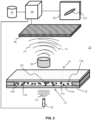
- FIG. 2 illustrates an example of an observation device 10 of a particle 11a-11f present in a sample 12.
- the sample 12 is arranged between a light source 15, spatially and temporally coherent (e.g. a laser) or pseudo-coherent (e.g. a light-emitting diode, a laser diode), and a digital sensor 16 sensitive in the spectral range of the light source.
- the light source 15 has a small spectral width, for example less than 200nm, less than 100nm or even less than 25nm.
- reference is made to the central emission wavelength of the light source for example in the visible range.
- the light source 15 emits a coherent signal Sn oriented on a first face 13 of the sample, for example conveyed by a waveguide such as an optical fiber.
- the sample 12 (as typically explained a culture medium) is contained in an analysis chamber, delimited vertically by a lower slide and an upper slide, for example conventional microscope slides.
- the analysis chamber is delimited laterally by an adhesive or any other impermeable material.
- the lower and upper slides are transparent to the wavelength of the light source 15, the sample and the chamber allowing for example more than 50% of the wavelength of the light source to pass under normal incidence on the lower slide.
- the particles 11a-11f are arranged in the sample 12 at the level of the upper slide.
- the lower face of the upper slide comprises for this purpose ligands allowing the particles to be attached, for example polycations (e.g. poly-Llysine) in the context of microorganisms.
- polycations e.g. poly-Llysine
- the particles 11a-11f can nevertheless move in the sample 12.
- the device comprises an optical system 23 consisting, for example, of a microscope objective and a tube lens, arranged in the air and at a fixed distance from the sample.
- the optical system 23 is optionally equipped with a filter that can be located in front of the objective or between the objective and the tube lens.
- the optical system 23 is characterized by its optical axis, its object plane, also called the focusing plane, at a distance from the objective, and its image plane, conjugated to the object plane by the optical system.
- an object located in the object plane corresponds to a sharp image of this object in the image plane, also called the focal plane.
- the optical properties of the system 23 are fixed (e.g. fixed focal length optics).
- the object and image planes are orthogonal to the optical axis.
- the image sensor 16 is located, opposite a second face 14 of the sample, in the focal plane or close to the latter.
- the sensor for example a CCD or CMOS sensor, comprises a periodic two-dimensional network of sensitive elementary sites, and proximity electronics which regulate the time exposure and resetting the sites, in a manner known per se.
- the output signal of an elementary site is a function of the quantity of radiation of the spectral range incident on said site during the exposure time. This signal is then converted, for example by proximity electronics, into an image point, or "pixel", of a digital image.
- the sensor thus produces a digital image in the form of a matrix with C columns and L rows.
- Each pixel of this matrix corresponds in a manner known per se to a position of Cartesian coordinates (x(c, l), y(c, l)) in the focal plane of the optical system 23, for example the position of the center of the elementary sensitive site of rectangular shape.
- the pitch and fill factor of the periodic grating are chosen to respect the Shannon-Nyquist criterion with respect to the size of the particles observed, so as to define at least two pixels per particle.
- the image sensor 16 acquires a transmission image of the sample in the spectral range of the light source.
- the image acquired by the image sensor 16 includes holographic information insofar as it results from the interference between a wave diffracted by the particles 11a-11f and a reference wave having passed through the sample without having interacted with it. It is obviously understood, as described above, that in the context of a CMOS or CCD sensor, the digital image acquired is an intensity image, the phase information therefore being coded here in this intensity image.
- the coherent signal Sn from the light source 15 into two components, for example by means of a semi-transparent plate.
- the first component serves as a reference wave and the second component is diffracted by the sample 12, the image in the image plane of the optical system 23 resulting from the interference between the diffracted wave and the reference wave.
- step (a) it is possible in step (a) to reconstruct from the hologram a plurality of global images of the sample 12, then to extract each input image from a global image of the sample.
- the target particle 11a-11f must be represented in a homogeneous manner in each input image, in particular centered and aligned in a predetermined direction (for example, the horizontal direction).
- the input images must also have a standardized size (it is also desirable that only the target particle 11a-11f be seen in the input image).
- the input image is thus called a "thumbnail"; for example, a size of 250x250 pixels can be defined.
- a sequence of input images for example, one image per minute is taken for a time interval of 120 minutes; a sequence of 120 input images is thus obtained.
- electromagnetic matrices typically, a series of complex matrices called “electromagnetic matrices” are constructed (for an acquisition instant), modeling from the intensity image of the sample 12 (the hologram) the light wavefront propagated along the optical axis for a plurality of deviations from the focusing plane of the optical system 23, and in particular deviations positioned in the sample.
- These matrices can be projected into real space (e.g. via the Hermitian norm), so as to constitute a stack of global images at various focusing distances.
- step (a) advantageously comprises the segmentation of said global images so as to detect said target particle in the sample, then the cropping.
- each input image can be extracted from one of the global images of the sample, so as to represent said target particle in said homogeneous manner.
- segmentation detects all particles of interest, removing artifacts such as filaments or microcolonies to improve the overall image(s), then one of the detected particles is selected as the target particle, and the corresponding thumbnail is extracted. As explained, this work can be done for all detected particles.
- Segmentation can be implemented in any known way. In the example of the Figure 3b , we start with a fine segmentation to eliminate artifacts, then we implement a less fine segmentation to this time detect particles 11a-11f. Those skilled in the art can use any known segmentation technique.
- tracking techniques can be implemented to follow any movements of the particle from one global image to the next.
- the present method is distinguished in that it can work directly on a sequence of input images, without needing to work image by image, nor to extract feature maps from intermediate way. Moreover, we will see that a very simple and lightweight CNN is enough to achieve a reliable and efficient classification.
- the present method comprises a step (b) of concatenating said input images of the sequence in the form of a three-dimensional stack, in other words a 3D "stack". More precisely, the input images all have the same size and form a sequence of matrices, it is therefore sufficient to stack them according to the order of the input images so as to obtain the three-dimensional stack.
- This three-dimensional stack can therefore be seen as an image presenting as many channels as there are acquisition time instants, even if, as we will see later, the present method will treat this stack in a very original way as a single three-dimensional object (for example, of size 250x250x120 if we have input images of size 250x250 and one image acquired per minute for 120 minutes) with a single channel, in the same way that an RGB image is a two-dimensional object with three channels.
- the first two dimensions are classically the spatial dimensions (i.e. the size of the input images) and the third dimension is the "temporal" dimension (acquisition time).
- step (b) comprises subsampling said three-dimensional stack, i.e. reducing the size of the input.
- Said subsampling can be implemented on the time dimension of the stack and/or its spatial dimensions, preferably both.
- this subsampling can be done upstream of the stack generation (by selecting and modifying the input images).
- said three-dimensional stack is classified directly by means of a suitable convolutional neural network, called "3D CNN” due to its ability to process three-dimensional objects that are stacks.
- 3D CNN a suitable convolutional neural network
- CNNs are particularly suitable for vision tasks and more particularly for image classification.
- a CNN uses a plurality of convolution layers, and the present 3D CNN uses at least one 3D convolution layer which models the spatio-temporal dependence between the different input images.
- a 3D convolution layer is a convolution layer that applies four-dimensional filters, and is thus able to work on multiple channels of already three-dimensional stacks, i.e., a four-dimensional feature map.
- the 3D convolution layer applies four-dimensional filters to a four-dimensional input feature map so as to generate a four-dimensional output feature map.
- the fourth and final dimension is semantic depth, as in any feature map.
- Our 3D convolution therefore applies four-dimensional filters of depth equal to the number of channels of three-dimensional stacks in input, and sweeps these filters over the entire volume of a three-dimensional stack, therefore the two spatial dimensions but also the temporal dimension, i.e. in 3D (hence the name 3D convolution).
- 3D convolution we thus obtain a three-dimensional stack per filter, i.e. a four-dimensional feature map.
- using a large number of filters certainly increases the semantic depth at the output (the number of channels), but we will always have a three-dimensional feature map.
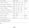
- Figure 5 represents the architecture of an embodiment of the present 3D CNN.
- this architecture advantageously comprises a succession of so-called convolution blocks composed of a 3D convolution layer, an activation layer (for example the ReLU function) to increase the depth of the feature maps, and a 3D pooling layer to reduce the size of the feature map (generally by a factor of 2).
- an activation layer for example the ReLU function
- a 3D pooling layer to reduce the size of the feature map (generally by a factor of 2).
- a 3D pooling layer is a layer capable of working on four-dimensional feature maps, having one or more channels of already three-dimensional stacks.
- the size reduction is over all dimensions of a three-dimensional stack, i.e. the first three dimensions of a four-dimensional feature map.
- the number of "dimensions" of the feature maps in the geometric sense, i.e. the number of independent directions in which these maps extend (for example, a vector is an object of dimension 1, an image is of dimension 2, and the present feature maps are of dimension 4), and the number of "variables" of these feature maps, i.e. the size according to each dimension, i.e. the number of independent degrees of freedom (which corresponds in practice to the notion of dimension in a vector space - more precisely, the set of feature maps having a given number of variables constitutes a vector space of dimension equal to this number of variables).
- the 3D CNN starts as explained with 6 layers divided into 2 blocks.
- the first takes as input the three-dimensional single-channel stack (thus forming an object of size 125x125x5x1 when it is advantageously downsampled as proposed above), and includes a convolution+ReLU sequence (a first 3D convolution layer, and an activation layer with ReLU function) raising the depth to 30 then a max pooling layer (one can also use global average pooling), with as output a feature map of size 62x62x2x30 (the 3D pooling layer works as explained on the three dimensions and not only the two spatial dimensions - so we divide by two including the temporal dimension).
- the second block has an identical architecture to the first block and generates as output of a new convolution+ReLU ensemble (a second 3D convolution layer, and an activation layer with ReLU function) a feature map of size 62x62x2x60 (doubled depth) and as output of the layer of max pooling a feature map of size 12x12x1x60 (note that the spatial size reduction is this time by a factor of five, but the temporal size reduction is still by a factor of two).
- a new convolution+ReLU ensemble a second 3D convolution layer, and an activation layer with ReLU function
- the 3D CNN advantageously includes a "flattening" layer transforming the "final" feature map (containing the "deepest” information) at the output of this block into a vector (object of dimension 1).
- a "flattening" layer transforming the "final" feature map (containing the "deepest” information) at the output of this block into a vector (object of dimension 1).
- FC fully connected layers
- the 3D CNN is composed of (i.e., includes exactly) a sequence of convolution blocks, then a flattening layer, and finally one or more fully connected layers.
- This final part of the 3D CNN returns the expected result, in this case the class of the input image sequence (the vector of size 2 corresponds to a binary result).
- the method may comprise a step (a0) of learning, by the data processing means 3 of the server 1, from a learning base, the parameters of the 3D CNN.
- This step is in fact typically implemented very early on, in particular by the remote server 1.
- the learning base may comprise a certain number of learning data, in particular sequences of images associated with their class (for example “division” or “no division” if binary classification).
- 3D CNN training can be performed in a classical way.
- the learning cost function can be composed of a classical data attachment - cross entropy - to be minimized via a gradient descent algorithm.
- the parameters of the learned CNN can be stored, if necessary, on data storage means 21 of the client 2 for use in classification. Note that the same CNN can be embedded on many clients 2, only one training is necessary.
- the invention relates to a computer program product comprising code instructions for the execution (in particular on the data processing means 3, 20 of the server 1 and/or the client 2) of a method for classifying an input image sequence representing a target particle 11a-11f in a sample 12, as well as storage means readable by computer equipment (a memory 4, 21 of the server 1 and/or the client 2) on which this computer program product is found.
Landscapes
- Engineering & Computer Science (AREA)
- Theoretical Computer Science (AREA)
- General Physics & Mathematics (AREA)
- Physics & Mathematics (AREA)
- Multimedia (AREA)
- Health & Medical Sciences (AREA)
- General Health & Medical Sciences (AREA)
- Evolutionary Computation (AREA)
- Computer Vision & Pattern Recognition (AREA)
- Life Sciences & Earth Sciences (AREA)
- Artificial Intelligence (AREA)
- Biomedical Technology (AREA)
- Molecular Biology (AREA)
- Databases & Information Systems (AREA)
- Software Systems (AREA)
- Medical Informatics (AREA)
- Computing Systems (AREA)
- Data Mining & Analysis (AREA)
- Bioinformatics & Cheminformatics (AREA)
- Bioinformatics & Computational Biology (AREA)
- Evolutionary Biology (AREA)
- General Engineering & Computer Science (AREA)
- Image Analysis (AREA)
- Apparatus Associated With Microorganisms And Enzymes (AREA)
- Measuring Or Testing Involving Enzymes Or Micro-Organisms (AREA)
- Information Retrieval, Db Structures And Fs Structures Therefor (AREA)
Claims (13)
- Verfahren zur Klassifizierung einer Sequenz von Eingangsbildern, die ein Zielpartikel (11a-11f) in einer Probe (12) im Zeitverlauf darstellt, wobei das Verfahren dadurch gekennzeichnet ist, dass es durch Datenverarbeitungsmittel (20) eines Clients (2) die Durchführung der folgenden Schritte umfasst:(b) Verketten der Eingangsbilder der Sequenz in Form eines dreidimensionalen Stapels;(c) direktes Klassifizieren des dreidimensionalen Stapels mittels eines neuronalen Faltungsnetzwerks, CNN, wobei das CNN aus einer Abfolge von Faltungsblöcken zusammengesetzt ist, die aus einer sogenannten 3D-Faltungsschicht zusammengesetzt sind, die auf eine Eingangs-Merkmalskarte der Dimension vier Filter der Dimension vier anwendet, um eine Ausgangs-Merkmalskarte der Dimension vier, eine Aktivierungsschicht und eine 3D-Pooling-Schicht, dann eine Abflachungsschicht und schließlich eine oder mehrere vollständig verbundene Schichten zu erzeugen,wobei die Abfolge von Faltungsblöcken mindestens zwei Faltungsblöcke umfasst, einen ersten Block und einen zweiten Block, wobei die 3D-Faltungsschicht des ersten Blocks 30 Filter der Dimension 3x3x3x1 und die 3D-Faltungsschicht des zweiten Blocks 60 Filter der Dimension 3x3x3x30 anwendet.
- Verfahren nach Anspruch 1, wobei die Partikel (11a-11f) in jedem Eingangsbild homogen, insbesondere zentriert und in einer vorbestimmten Richtung ausgerichtet, dargestellt werden.
- Verfahren nach Anspruch 2, umfassend einen Schritt (a) des Extrahierens jedes Eingangsbildes aus einem Gesamtbild der Probe, um das Zielpartikel (11a-11f) auf diese homogene Weise darzustellen.
- Verfahren nach Anspruch 3, wobei die Extraktion der Schritt (a) für jedes Eingangsbild die Segmentierung des Gesamtbildes, um das Zielpartikel (11a-11f) in der Probe (12) zu erkennen, und dann das Zuschneiden des Eingangsbildes auf das erkannte Zielpartikel (11a-11f) umfasst.
- Verfahren nach einem der Ansprüche 3 und 4, wobei Schritt (a) das Erhalten des Gesamtbildes aus einem Intensitätsbild der Probe (12) umfasst, das von einer Beobachtungsvorrichtung (10) erfasst wird.
- Verfahren nach einem der vorhergehenden Ansprüche, wobei der dreidimensionale Stapel zwei räumliche Dimensionen und eine zeitliche Dimension aufweist, wobei die Filter und Merkmalskarten als erste drei Dimensionen die räumlichen und zeitliche Dimension/en und als vierte Dimension eine semantische Tiefe aufweisen.
- Verfahren nach Anspruch 6, wobei die Filter der 3D-Faltungsschicht eine Tiefe aufweisen, die gleich der Tiefe der Eingangs-Merkmalskarte ist, und die Ausgangs-Merkmalskarte eine Tiefe aufweist, die gleich der Anzahl der Filter der 3D-Faltungsschicht ist.
- Verfahren nach einem der vorhergehenden Ansprüche, wobei das CNN nur zwei Faltungsblöcke umfasst.
- Verfahren nach einem der Ansprüche 1 bis 8, das einen Schritt (a0) des Lernens der Parameter des CNN durch Datenverarbeitungsmittel (3) eines Servers (1) anhand einer Trainingsbasis bereits klassifizierter Sequenzen von Partikelbildern (11a-11f) in der Probe (12) umfasst.
- System zur Klassifizierung einer Eingangsbildsequenz, die ein Zielpartikel (11a-11f) in einer Probe (12) im Zeitverlauf darstellt, umfassend mindestens einen Client (2), der Datenverarbeitungsmittel (20) umfasst, dadurch gekennzeichnet, dass die Datenverarbeitungsmittel (20) ausgelegt sind, um zu implementieren:- die Verkettung der Eingangsbilder der Sequenz in Form eines dreidimensionalen Stapels;- die direkte Klassifizierung des dreidimensionalen Stapels mittels eines neuronalen Faltungsnetzwerks, CNN, wobei das CNN aus einer Abfolge von Faltungsblöcken zusammengesetzt ist, die aus einer sogenannten 3D-Faltungsschicht zusammengesetzt sind, die auf eine Eingangs-Merkmalskarte der Dimension vier Filter der Dimension vier anwendet, um eine Ausgangs-Merkmalskarte der Dimension vier, eine Aktivierungsschicht und eine 3D-Pooling-Schicht, dann eine Abflachungsschicht und schließlich eine oder mehrere vollständig verbundene Schichten zu erzeugen,wobei die Abfolge von Faltungsblöcken mindestens zwei Faltungsblöcke umfasst, einen ersten Block und einen zweiten Block, wobei die 3D-Faltungsschicht des ersten Blocks 30 Filter der Dimension 3x3x3x1 und die 3D-Faltungsschicht des zweiten Blocks 60 Filter der Dimension 3x3x3x30 anwendet.
- System nach Anspruch 10, das ferner eine Vorrichtung (10) zur Beobachtung des Zielpartikels (11a-11f) in der Probe (12) umfasst.
- Rechnerprogrammprodukt, das Codeanweisungen für die Ausführung eines Verfahrens nach einem der Ansprüche 1 bis 9 zur Klassifizierung einer Eingangsbildsequenz umfasst, die ein Zielpartikel (11a-11f) in einer Probe (12) im Zeitverlauf darstellt, wenn das Programm auf einem Rechner ausgeführt wird.
- Speichermedium, das von einer IT-Ausrüstung lesbar ist, auf dem ein Rechnerprogrammprodukt Codeanweisungen für die Ausführung eines Verfahrens nach einem der Ansprüche 1 bis 9 zur Klassifizierung einer Eingangsbildsequenz umfasst, die ein Zielpartikel (11a-11f) in einer Probe (12) im Zeitverlauf darstellt.
Applications Claiming Priority (2)
| Application Number | Priority Date | Filing Date | Title |
|---|---|---|---|
| FR2010744 | 2020-10-20 | ||
| PCT/FR2021/051817 WO2022084616A1 (fr) | 2020-10-20 | 2021-10-19 | Procédé de classification d'une séquence d'images d'entrée représentant une particule dans un échantillon au cours du temps |
Publications (3)
| Publication Number | Publication Date |
|---|---|
| EP4232946A1 EP4232946A1 (de) | 2023-08-30 |
| EP4232946B1 true EP4232946B1 (de) | 2025-04-23 |
| EP4232946C0 EP4232946C0 (de) | 2025-04-23 |
Family
ID=74183333
Family Applications (1)
| Application Number | Title | Priority Date | Filing Date |
|---|---|---|---|
| EP21807183.5A Active EP4232946B1 (de) | 2020-10-20 | 2021-10-19 | Verfahren zur klassifizierung einer sequenz von eingabebildern, die ein teilchen in einer probe im laufe der zeit darstellen |
Country Status (6)
| Country | Link |
|---|---|
| US (1) | US12511919B2 (de) |
| EP (1) | EP4232946B1 (de) |
| JP (1) | JP7845610B2 (de) |
| CN (1) | CN116888644B (de) |
| ES (1) | ES3033863T3 (de) |
| WO (1) | WO2022084616A1 (de) |
Families Citing this family (3)
| Publication number | Priority date | Publication date | Assignee | Title |
|---|---|---|---|---|
| FR3115386A1 (fr) * | 2020-10-20 | 2022-04-22 | Biomerieux | Procédé de classification d’une image d’entrée représentant une particule dans un échantillon |
| FR3141785B1 (fr) * | 2022-11-03 | 2024-12-13 | Fond B Com | Procédé et dispositif d’estimation d’une carte de profondeur associée à un hologramme numérique représentant une scène et programme d’ordinateur associé |
| CN118963090B (zh) * | 2024-09-20 | 2025-10-17 | 北京航空航天大学 | 一种基于焦点堆栈网络的高保真全息图生成方法 |
Family Cites Families (9)
| Publication number | Priority date | Publication date | Assignee | Title |
|---|---|---|---|---|
| JP2013538567A (ja) | 2010-08-12 | 2013-10-17 | ザ リージェンツ オブ ザ ユニバーシティ オブ カリフォルニア | 抗菌化合物を同定するおよび抗生物質感受性を決定する方法 |
| US11024024B2 (en) | 2015-12-15 | 2021-06-01 | The Regents Of The University Of California | Systems and methods for analyzing perfusion-weighted medical imaging using deep neural networks |
| EP3252455A1 (de) | 2016-05-30 | 2017-12-06 | Biomérieux | Vorrichtung und verfahren zur erfassung eines partikels, das in einer probe enthalten ist |
| CN108427958B (zh) * | 2018-02-02 | 2021-06-01 | 哈尔滨工程大学 | 基于深度学习的自适应权值卷积神经网络水下声纳图像分类方法 |
| EP3660785A1 (de) * | 2018-11-30 | 2020-06-03 | Laralab UG | Verfahren und system zur bereitstellung von mindestens einer segmentierung eines dreidimensionalen medizinischen bildes einer struktur eines inneren organs |
| US11151356B2 (en) * | 2019-02-27 | 2021-10-19 | Fei Company | Using convolution neural networks for on-the-fly single particle reconstruction |
| CN110222598B (zh) * | 2019-05-21 | 2022-09-27 | 平安科技(深圳)有限公司 | 一种视频行为识别方法、装置、存储介质和服务器 |
| CN110781830B (zh) * | 2019-10-28 | 2023-03-10 | 西安电子科技大学 | 基于空-时联合卷积的sar序列图像分类方法 |
| US20230022775A1 (en) * | 2019-12-13 | 2023-01-26 | President And Fellows Of Harvard College | Riboregulators and methods of use thereof |
-
2021
- 2021-10-19 ES ES21807183T patent/ES3033863T3/es active Active
- 2021-10-19 US US18/032,399 patent/US12511919B2/en active Active
- 2021-10-19 CN CN202180072004.9A patent/CN116888644B/zh active Active
- 2021-10-19 JP JP2023524074A patent/JP7845610B2/ja active Active
- 2021-10-19 WO PCT/FR2021/051817 patent/WO2022084616A1/fr not_active Ceased
- 2021-10-19 EP EP21807183.5A patent/EP4232946B1/de active Active
Also Published As
| Publication number | Publication date |
|---|---|
| JP7845610B2 (ja) | 2026-04-14 |
| JP2023546193A (ja) | 2023-11-01 |
| US12511919B2 (en) | 2025-12-30 |
| CN116888644A (zh) | 2023-10-13 |
| US20230386233A1 (en) | 2023-11-30 |
| EP4232946A1 (de) | 2023-08-30 |
| WO2022084616A1 (fr) | 2022-04-28 |
| CN116888644B (zh) | 2026-04-07 |
| EP4232946C0 (de) | 2025-04-23 |
| ES3033863T3 (en) | 2025-08-08 |
Similar Documents
| Publication | Publication Date | Title |
|---|---|---|
| EP3465153B1 (de) | Vorrichtung und verfahren zur erfassung eines partikels, das in einer probe enthalten ist | |
| EP3274694B1 (de) | Verfahren zur bestimmung des zustandes einer zelle | |
| EP3274689B1 (de) | Verfahren und vorrichtung zur analyse von partikeln | |
| EP4232946B1 (de) | Verfahren zur klassifizierung einer sequenz von eingabebildern, die ein teilchen in einer probe im laufe der zeit darstellen | |
| EP3433678A1 (de) | Holographisches verfahren zur charakterisierung eines partikels in einer probe | |
| EP3234550A1 (de) | Verfahren zur identifizierung biologischer partikel mit stapeln von defokussierten holografischen bildern | |
| EP4232948B1 (de) | Verfahren zur klassifizierung eines eingabebildes zur darstellung eines partikels in einer probe | |
| EP3637194B1 (de) | Verfahren zu bestimmung der parameter eines teilchens | |
| EP3584560A1 (de) | Verfahren zur beobachtung einer probe mit linsenloser bildgebung unter berücksichtigung einer räumlichen dispersion in der probe | |
| FR3056749A1 (fr) | Procede de numeration de leucocytes dans un echantillon | |
| EP4233014A1 (de) | Verfahren zur klassifizierung eines eingabebildes zur darstellung eines partikels in einer probe | |
| EP4233018B1 (de) | Verfahren zur klassifizierung eines eingabebildes mit einem partikel in einer probe | |
| EP3995991A2 (de) | Verfahren zur erfassung eines zellulären ereignisses | |
| WO2019135060A1 (fr) | Système d'imagerie holographique et procédé d'analyse par imagerie holographique avec détection de défauts dans la chambre d'observation | |
| EP4502732A1 (de) | Verfahren und system zur charakterisierung von mikroorganismen mittels digitaler holographischer mikroskopie | |
| WO2025027155A1 (fr) | Procédé et système de caractérisation de microorganismes par microscopie holographique numérique | |
| EP4394730A1 (de) | Verfahren zur verarbeitung eines bildes einer probe mit biologischen partikeln | |
| FR3138522A1 (fr) | Dispositif de détection de particules en imagerie sans lentille |
Legal Events
| Date | Code | Title | Description |
|---|---|---|---|
| STAA | Information on the status of an ep patent application or granted ep patent |
Free format text: STATUS: UNKNOWN |
|
| STAA | Information on the status of an ep patent application or granted ep patent |
Free format text: STATUS: THE INTERNATIONAL PUBLICATION HAS BEEN MADE |
|
| PUAI | Public reference made under article 153(3) epc to a published international application that has entered the european phase |
Free format text: ORIGINAL CODE: 0009012 |
|
| STAA | Information on the status of an ep patent application or granted ep patent |
Free format text: STATUS: REQUEST FOR EXAMINATION WAS MADE |
|
| 17P | Request for examination filed |
Effective date: 20230517 |
|
| AK | Designated contracting states |
Kind code of ref document: A1 Designated state(s): AL AT BE BG CH CY CZ DE DK EE ES FI FR GB GR HR HU IE IS IT LI LT LU LV MC MK MT NL NO PL PT RO RS SE SI SK SM TR |
|
| DAV | Request for validation of the european patent (deleted) | ||
| DAX | Request for extension of the european patent (deleted) | ||
| REG | Reference to a national code |
Ref country code: DE Ref legal event code: R079 Free format text: PREVIOUS MAIN CLASS: G06K0009000000 Ipc: G06V0020690000 Ref document number: 602021029706 Country of ref document: DE |
|
| GRAP | Despatch of communication of intention to grant a patent |
Free format text: ORIGINAL CODE: EPIDOSNIGR1 |
|
| STAA | Information on the status of an ep patent application or granted ep patent |
Free format text: STATUS: GRANT OF PATENT IS INTENDED |
|
| RIC1 | Information provided on ipc code assigned before grant |
Ipc: G06V 20/69 20220101AFI20241025BHEP |
|
| INTG | Intention to grant announced |
Effective date: 20241120 |
|
| GRAS | Grant fee paid |
Free format text: ORIGINAL CODE: EPIDOSNIGR3 |
|
| GRAA | (expected) grant |
Free format text: ORIGINAL CODE: 0009210 |
|
| STAA | Information on the status of an ep patent application or granted ep patent |
Free format text: STATUS: THE PATENT HAS BEEN GRANTED |
|
| AK | Designated contracting states |
Kind code of ref document: B1 Designated state(s): AL AT BE BG CH CY CZ DE DK EE ES FI FR GB GR HR HU IE IS IT LI LT LU LV MC MK MT NL NO PL PT RO RS SE SI SK SM TR |
|
| REG | Reference to a national code |
Ref country code: GB Ref legal event code: FG4D Free format text: NOT ENGLISH |
|
| REG | Reference to a national code |
Ref country code: CH Ref legal event code: EP |
|
| REG | Reference to a national code |
Ref country code: DE Ref legal event code: R096 Ref document number: 602021029706 Country of ref document: DE |
|
| REG | Reference to a national code |
Ref country code: IE Ref legal event code: FG4D Free format text: LANGUAGE OF EP DOCUMENT: FRENCH |
|
| U01 | Request for unitary effect filed |
Effective date: 20250512 |
|
| U07 | Unitary effect registered |
Designated state(s): AT BE BG DE DK EE FI FR IT LT LU LV MT NL PT RO SE SI Effective date: 20250516 |
|
| REG | Reference to a national code |
Ref country code: ES Ref legal event code: FG2A Ref document number: 3033863 Country of ref document: ES Kind code of ref document: T3 Effective date: 20250808 |
|
| PG25 | Lapsed in a contracting state [announced via postgrant information from national office to epo] |
Ref country code: NO Free format text: LAPSE BECAUSE OF FAILURE TO SUBMIT A TRANSLATION OF THE DESCRIPTION OR TO PAY THE FEE WITHIN THE PRESCRIBED TIME-LIMIT Effective date: 20250723 Ref country code: GR Free format text: LAPSE BECAUSE OF FAILURE TO SUBMIT A TRANSLATION OF THE DESCRIPTION OR TO PAY THE FEE WITHIN THE PRESCRIBED TIME-LIMIT Effective date: 20250724 |
|
| PG25 | Lapsed in a contracting state [announced via postgrant information from national office to epo] |
Ref country code: PL Free format text: LAPSE BECAUSE OF FAILURE TO SUBMIT A TRANSLATION OF THE DESCRIPTION OR TO PAY THE FEE WITHIN THE PRESCRIBED TIME-LIMIT Effective date: 20250423 |
|
| PG25 | Lapsed in a contracting state [announced via postgrant information from national office to epo] |
Ref country code: HR Free format text: LAPSE BECAUSE OF FAILURE TO SUBMIT A TRANSLATION OF THE DESCRIPTION OR TO PAY THE FEE WITHIN THE PRESCRIBED TIME-LIMIT Effective date: 20250423 |
|
| PG25 | Lapsed in a contracting state [announced via postgrant information from national office to epo] |
Ref country code: RS Free format text: LAPSE BECAUSE OF FAILURE TO SUBMIT A TRANSLATION OF THE DESCRIPTION OR TO PAY THE FEE WITHIN THE PRESCRIBED TIME-LIMIT Effective date: 20250723 |
|
| PG25 | Lapsed in a contracting state [announced via postgrant information from national office to epo] |
Ref country code: IS Free format text: LAPSE BECAUSE OF FAILURE TO SUBMIT A TRANSLATION OF THE DESCRIPTION OR TO PAY THE FEE WITHIN THE PRESCRIBED TIME-LIMIT Effective date: 20250823 |
|
| U20 | Renewal fee for the european patent with unitary effect paid |
Year of fee payment: 5 Effective date: 20251027 |
|
| PGFP | Annual fee paid to national office [announced via postgrant information from national office to epo] |
Ref country code: GB Payment date: 20251027 Year of fee payment: 5 |
|
| PG25 | Lapsed in a contracting state [announced via postgrant information from national office to epo] |
Ref country code: SM Free format text: LAPSE BECAUSE OF FAILURE TO SUBMIT A TRANSLATION OF THE DESCRIPTION OR TO PAY THE FEE WITHIN THE PRESCRIBED TIME-LIMIT Effective date: 20250423 |
|
| PG25 | Lapsed in a contracting state [announced via postgrant information from national office to epo] |
Ref country code: CZ Free format text: LAPSE BECAUSE OF FAILURE TO SUBMIT A TRANSLATION OF THE DESCRIPTION OR TO PAY THE FEE WITHIN THE PRESCRIBED TIME-LIMIT Effective date: 20250423 |
|
| PGFP | Annual fee paid to national office [announced via postgrant information from national office to epo] |
Ref country code: IE Payment date: 20251027 Year of fee payment: 5 |
|
| PG25 | Lapsed in a contracting state [announced via postgrant information from national office to epo] |
Ref country code: SK Free format text: LAPSE BECAUSE OF FAILURE TO SUBMIT A TRANSLATION OF THE DESCRIPTION OR TO PAY THE FEE WITHIN THE PRESCRIBED TIME-LIMIT Effective date: 20250423 |
|
| PGFP | Annual fee paid to national office [announced via postgrant information from national office to epo] |
Ref country code: ES Payment date: 20251103 Year of fee payment: 5 |
|
| PLBE | No opposition filed within time limit |
Free format text: ORIGINAL CODE: 0009261 |
|
| STAA | Information on the status of an ep patent application or granted ep patent |
Free format text: STATUS: NO OPPOSITION FILED WITHIN TIME LIMIT |
|
| REG | Reference to a national code |
Ref country code: CH Ref legal event code: L10 Free format text: ST27 STATUS EVENT CODE: U-0-0-L10-L00 (AS PROVIDED BY THE NATIONAL OFFICE) Effective date: 20260304 |
|
| 26N | No opposition filed |
Effective date: 20260126 |